signals and system analysis - university of...
TRANSCRIPT

Programming
MATLAB
EXEL

compressor turbine
combustion1
2
5
3
4
Shaft power
Simple cycle

%example 1%Gas turbine with no heat-exchanger
clear all;
Cpa=1005;Cpg=1146;R=287;eta_comp=0.81;eta_comb=0.98;eta_comb_p=0.95;eta_turb=0.85;mass_flow_rate=0.6;gama_a=1.4;gama_g=1.333;bearing_loss=3000;fuel_heat=43e6;
%inletP1=0.101;T1=288;S1=Cpa*log(T1/273)-R*log(P1/0.101);
%compressor 100% efficiencyP2=5*P1;T2a=T1*(P2/P1)^((gama_a-1)/gama_a);S2a=Cpa*log(T2a/273)-R*log(P2/0.101);
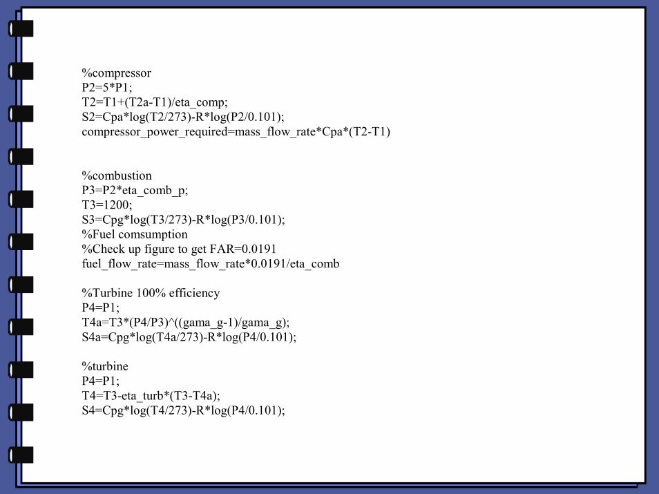
%compressorP2=5*P1;T2=T1+(T2a-T1)/eta_comp;S2=Cpa*log(T2/273)-R*log(P2/0.101);compressor_power_required=mass_flow_rate*Cpa*(T2-T1)
%combustionP3=P2*eta_comb_p;T3=1200;S3=Cpg*log(T3/273)-R*log(P3/0.101);%Fuel comsumption%Check up figure to get FAR=0.0191fuel_flow_rate=mass_flow_rate*0.0191/eta_comb
%Turbine 100% efficiencyP4=P1;T4a=T3*(P4/P3)^((gama_g-1)/gama_g);S4a=Cpg*log(T4a/273)-R*log(P4/0.101);
%turbineP4=P1;T4=T3-eta_turb*(T3-T4a);S4=Cpg*log(T4/273)-R*log(P4/0.101);
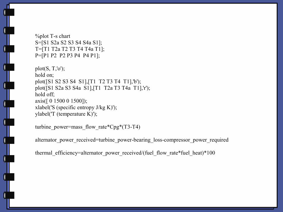
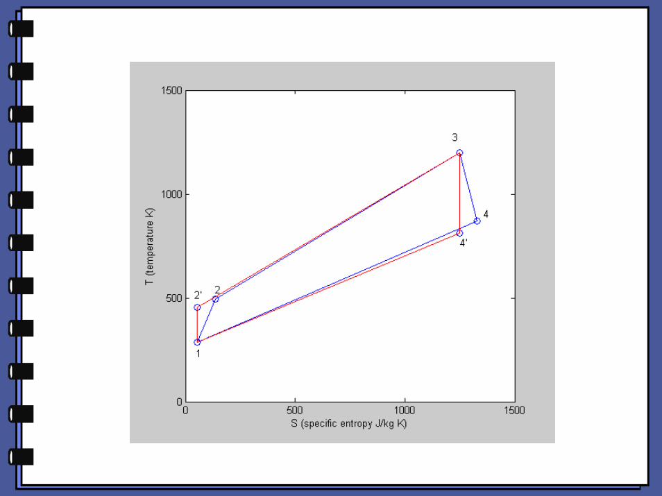
%plot T-s chartS=[S1 S2a S2 S3 S4 S4a S1];T=[T1 T2a T2 T3 T4 T4a T1];P=[P1 P2 P2 P3 P4 P4 P1];
plot(S, T,'o');hold on;plot([S1 S2 S3 S4 S1],[T1 T2 T3 T4 T1],'b');plot([S1 S2a S3 S4a S1],[T1 T2a T3 T4a T1],'r');hold off;axis([ 0 1500 0 1500]);xlabel('S (specific entropy J/kg K)');ylabel('T (temperature K)');
turbine_power=mass_flow_rate*Cpg*(T3-T4)
alternator_power_received=turbine_power-bearing_loss-compressor_power_required
thermal_efficiency=alternator_power_received/(fuel_flow_rate*fuel_heat)*100
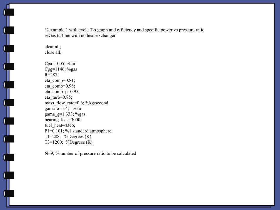
%example 1 with cycle T-s graph and efficiency and specific power vs pressure ratio%Gas turbine with no heat-exchanger
clear all;close all;
Cpa=1005; %airCpg=1146; %gasR=287;eta_comp=0.81;eta_comb=0.98;eta_comb_p=0.95;eta_turb=0.85;mass_flow_rate=0.6; %kg/secondgama_a=1.4; %airgama_g=1.333; %gasbearing_loss=3000;fuel_heat=43e6;P1=0.101; %1 standard atmosphereT1=288; %Degrees (K)T3=1200; %Degrees (K)
N=9; %number of pressure ratio to be calculated
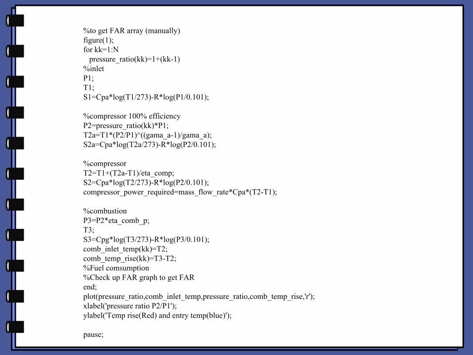
%to get FAR array (manually)figure(1);for kk=1:N pressure_ratio(kk)=1+(kk-1) %inletP1;T1;S1=Cpa*log(T1/273)-R*log(P1/0.101);
%compressor 100% efficiencyP2=pressure_ratio(kk)*P1;T2a=T1*(P2/P1)^((gama_a-1)/gama_a);S2a=Cpa*log(T2a/273)-R*log(P2/0.101);
%compressorT2=T1+(T2a-T1)/eta_comp;S2=Cpa*log(T2/273)-R*log(P2/0.101);compressor_power_required=mass_flow_rate*Cpa*(T2-T1);
%combustionP3=P2*eta_comb_p;T3;S3=Cpg*log(T3/273)-R*log(P3/0.101);comb_inlet_temp(kk)=T2;comb_temp_rise(kk)=T3-T2;%Fuel comsumption%Check up FAR graph to get FARend;plot(pressure_ratio,comb_inlet_temp,pressure_ratio,comb_temp_rise,'r');xlabel('pressure ratio P2/P1');ylabel('Temp rise(Red) and entry temp(blue)');
pause;

%Using the FAR graph to input those FAR figure manually:
FAR(1)=0.024;FAR(2)=0.0225;FAR(3)=0.0215;FAR(4)=0.0205;FAR(5)=0.0191;FAR(6)=0.018;FAR(7)=0.0175;FAR(8)=0.0169;FAR(9)=0.0165;

%calculation efficiency and specific power in different pressure ratiofigure(2);for kk=1:N
%inletP1;T1;S1=Cpa*log(T1/273)-R*log(P1/0.101);
%compressor 100% efficiencyP2=pressure_ratio(kk)*P1;T2a=T1*(P2/P1)^((gama_a-1)/gama_a);S2a=Cpa*log(T2a/273)-R*log(P2/0.101);
%compressorT2=T1+(T2a-T1)/eta_comp;S2=Cpa*log(T2/273)-R*log(P2/0.101);compressor_power_required=mass_flow_rate*Cpa*(T2-T1)
%combustionP3=P2*eta_comb_p;T3;S3=Cpg*log(T3/273)-R*log(P3/0.101);%Fuel comsumptionfuel_flow_rate=mass_flow_rate*FAR(kk)/eta_comb
%Turbine 100% efficiencyP4=P1;T4a=T3*(P4/P3)^((gama_g-1)/gama_g);S4a=Cpg*log(T4a/273)-R*log(P4/0.101);
%turbineP4=P1;T4=T3-eta_turb*(T3-T4a);S4=Cpg*log(T4/273)-R*log(P4/0.101);

%plot T-s chartS=[S1 S2a S2 S3 S4 S4a S1];T=[T1 T2a T2 T3 T4 T4a T1];P=[P1 P2 P2 P3 P4 P4 P1];
plot(S, T,'o'); hold on;plot([S1 S2 S3 S4 S1],[T1 T2 T3 T4 T1],'b');plot([S1 S2a S3 S4a S1],[T1 T2a T3 T4a T1],'r');hold off;axis([ 0 1500 0 1500]);xlabel('S (specific entropy J/kg K)');ylabel('T (temperature K)');
turbine_power=mass_flow_rate*Cpg*(T3-T4)
%specific_power(kk)=(Cpg*(T3-T4)-Cpa*(T2-T1))
alternator_power_received=turbine_power-bearing_loss-compressor_power_requiredspecific_power(kk)=alternator_power_received/mass_flow_rate
thermal_efficiency(kk)=alternator_power_received/(fuel_flow_rate*fuel_heat)*100exhaust_temp(kk)=T4;end;

figure(3);subplot(2,1,1);plot(pressure_ratio,thermal_efficiency);title('thermal efficiency and specific power vs pressure ratio');ylabel('thermal efficiency %');subplot(2,1,2);plot(pressure_ratio,specific_power);ylabel('specific power W/(kg/s)');xlabel('pressure ratio');
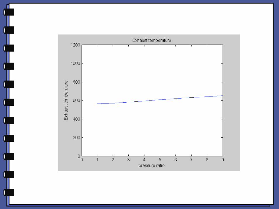
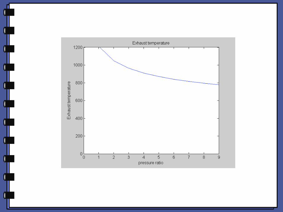
figure(4);%Exhaust temperatureplot(pressure_ratio,exhaust_temp);ylabel('Exhaust temperature');xlabel('pressure ratio');title('Exhaust temperature');

Pressure ratio =9

Using Excel, thermal efficiency and specific work may beseparately calculated. Then, input to the columns ofspreadsheet to display:
thermal efficiency vs pressure ratio
specific power vs pressure ratio


0510152025
0 5 10
Pressure ratio
Efficiency %
Specific power
KW/(kg/s)
050100150200
0 5 10

Recuperated cycle

%example 2 with cycle T-s graph and efficiency and specific power vs pressure ratio %Gas turbine with no heat-exchanger
clear all;close all;
Cpa=1005; %airCpg=1146; %gasR=287;eta_comp=0.81;eta_comb=0.98;eta_comb_p=0.95;eta_turb=0.85;mass_flow_rate=0.6; %kg/secondgama_a=1.4; %airgama_g=1.333; %gasbearing_loss=3000; fuel_heat=43e6;P1=0.101; %1 standard atmosphereT1=288; %Degrees (K)T3=1200; %Degrees (K)
eta_heat_exch=0.8; %heat exchanger parameters
N=9; %number of pressure ratio to be calculated
%to get FAR array (manually)figure(1);for kk=1:N pressure_ratio(kk)=1+(kk-1) %inletP1;T1;S1=Cpa*log(T1/273)-R*log(P1/0.101);
%compressor 100% efficiencyP2=pressure_ratio(kk)*P1;T2a=T1*(P2/P1)^((gama_a-1)/gama_a);S2a=Cpa*log(T2a/273)-R*log(P2/0.101);
%compressorT2=T1+(T2a-T1)/eta_comp;S2=Cpa*log(T2/273)-R*log(P2/0.101);compressor_power_required=mass_flow_rate*Cpa*(T2-T1);
%combustionP3=P2*eta_comb_p;T3;S3=Cpg*log(T3/273)-R*log(P3/0.101);
%Turbine 100% efficiencyP4=P1;T4a=T3*(P4/P3)^((gama_g-1)/gama_g);S4a=Cpg*log(T4a/273)-R*log(P4/0.101);
%turbineP4=P1;T4=T3-eta_turb*(T3-T4a);S4=Cpg*log(T4/273)-R*log(P4/0.101);
%heat exchangerP5= P2;T5=T2+eta_heat_exch*(T4-T2);S5=Cpa*log(T5/273)-R*log(P5/0.101);
comb_inlet_temp(kk)=T5;comb_temp_rise(kk)=T3-T5;%Fuel comsumption%Check up FAR graph to get FARend;plot(pressure_ratio,comb_inlet_temp,'b');hold on;plot(pressure_ratio,comb_temp_rise,'r');xlabel('pressure ratio P2/P1');ylabel('Temp rise(Red) and entry temp(blue)');hold off;
pause;
%Using the FAR graph to input those FAR figure manually:
FAR(1)=0.005;FAR(2)=0.0085;FAR(3)=0.0098;FAR(4)=0.0108;FAR(5)=0.0112;FAR(6)=0.0116;FAR(7)=0.0121;FAR(8)=0.0123;FAR(9)=0.0125;

%calculation efficiency and specific power in different pressure ratiofigure(2);for kk=1:N
%inletP1;T1;S1=Cpa*log(T1/273)-R*log(P1/0.101);
%compressor 100% efficiencyP2=pressure_ratio(kk)*P1;T2a=T1*(P2/P1)^((gama_a-1)/gama_a);S2a=Cpa*log(T2a/273)-R*log(P2/0.101);
%compressorT2=T1+(T2a-T1)/eta_comp;S2=Cpa*log(T2/273)-R*log(P2/0.101);compressor_power_required=mass_flow_rate*Cpa*(T2-T1)
%combustionP3=P2*eta_comb_p;T3;S3=Cpg*log(T3/273)-R*log(P3/0.101);%Fuel comsumptionfuel_flow_rate=mass_flow_rate*FAR(kk)/eta_comb
%Turbine 100% efficiencyP4=P1;T4a=T3*(P4/P3)^((gama_g-1)/gama_g);S4a=Cpg*log(T4a/273)-R*log(P4/0.101);
%turbineP4=P1;T4=T3-eta_turb*(T3-T4a);S4=Cpg*log(T4/273)-R*log(P4/0.101);
%heat exchangerP5= P2;T5=T2+eta_heat_exch*(T4-T2);S5=Cpa*log(T5/273)-R*log(P5/0.101);
%exhaust P6=P1;T6=T4-Cpa*(T5-T2)/Cpg;S6=Cpa*log(T6/273)-R*log(P6/0.101);
%plot T-s chartS=[S1 S2a S2 S5 S3 S4 S4a S6 S1];T=[T1 T2a T2 T5 T3 T4 T4a T6 T1];P=[P1 P2 P2 P5 P3 P4 P4 P6 P1];
plot(S, T,'o'); hold on;plot([S1 S2 S5 S3 S4 S6 S1],[T1 T2 T5 T3 T4 T6 T1],'b');plot([S1 S2a S3 S4a S1],[T1 T2a T3 T4a T1],'r');hold off;axis([ 0 1500 0 1500]);xlabel('S (specific entropy J/kg K)');ylabel('T (temperature K)');
turbine_power=mass_flow_rate*Cpg*(T3-T4)
%specific_power(kk)=(Cpg*(T3-T4)-Cpa*(T2-T1))
alternator_power_received=turbine_power-bearing_loss-compressor_power_requiredspecific_power(kk)=alternator_power_received/mass_flow_rate thermal_efficiency(kk)=alternator_power_received/(fuel_flow_rate*fuel_heat)*100exhaust_temp(kk)=T6;end;
figure(3);subplot(2,1,1);plot(pressure_ratio,thermal_efficiency);title('thermal efficiency and specific power vs pressure ratio');ylabel('thermal efficiency %');subplot(2,1,2);plot(pressure_ratio,specific_power);ylabel('specific power W/(kg/s)');xlabel('pressure ratio');
figure(4);%Exhaust temperatureplot(pressure_ratio,exhaust_temp);ylabel('Exhaust temperature');xlabel('pressure ratio');title('Exhaust temperature');axis([0 N 0 T3]);