sil 2 temperature signal converter multifunction, din … · d6072 - sil 2 temperature signal...
TRANSCRIPT

D6072 - SIL 2 Temperature Signal Converter G.M. International ISM0216-1
SIL 2 Temperature Signal Converter Multifunction, DIN-Rail and Termination Board,
Models D6072S, D6072D
D6072S - D6072D
INSTRUCTION & SAFETY MANUAL

2 D6072 - SIL 2 Temperature Signal Converter G.M. International ISM0216-1
General Description: The single and dual channel Temperature Signal Converter D6072S and D6072D accepts a low level dc signal from millivolt, thermocouple or 2-3-4 wire resistance/RTD or transmitting potentiometer sensor and converts, with isolation, the signal to drive a load, suitable for applications requiring SIL 2 level (according to IEC 61511) in safety related systems for high risk industries. Output signal can be direct or reverse.Modbus RTU RS-485 output is available on Bus connector. Cold junction compensation can be programmed as:
- Automatic: provided by an internal temperature sensor; - Fixed: to a user-customizable temperature value;
- Remote: (only D6072D) connecting compensation RTD to one of the two ch. For D6072D module: duplicator function provides two independent outputs from one single input. Output function can be configured as: Adder, subtractor, low/high selector. Modules are provided with alarm function, which is available via photoMOS output, Termination Board and Power Bus. Mounting on standard DIN-Rail, with or without Power Bus, or on customized Termination Boards, in Safe Area.
Fault Detection: D6072S and D6072D modules are able to detect multiple fault sources: - Sensor Burnout (i.e. when input is disconnected); - Sensor out of configured range; - Analog output saturation (beyond user-configured output limits); - Internal module fault; - Module out of allowed temperature range (-40 to + 70 °C). Modules can be programmed to reflect fault status on Analog or Alarm Output. All data is available also via Modbus Output.
Technical Data
Characteristics
Supply: 24 Vdc nom (18 to 30 Vdc) reverse polarity protected, ripple within voltage limits ≤ 5 Vpp, 2 A time lag fuse internally protected. Current consumption @ 24 V: 55 mA (D6072D), 45 mA (D6072S) with 20 mA out typical. Power dissipation: 1.15 W for 2 channels D6072D, 1.0 W for 1 channel D6072S with 24 V supply voltage and 20 mA output typical.
Isolation (Test Voltage): I.S. In/Out 2.5 KV; I.S. In/Supply 2.5 KV; I.S. In/I.S. In 500 V; Out/Supply 500 V; Out/Out 500 V.
Input: millivolt or thermocouple type A1, A2, A3, B, E, J, K, L, LR, N, R, S, T, U, or 2-3-4 wire RTD Pt50, Pt100, Pt200, Pt300, Pt400, Pt500, Pt1000 (IEC), Pt100 (ANSI 0.3916), Ni100, Ni120 (DIN43760), Pt46, Pt50, Pt100, Pt200, Pt300, Pt400, Pt500, Cu50, Cu53, Cu100 (GOST6651 russian standard) and Cu9.035 (or Cu10), or 3 wire transmitting potentiometer (100 Ω to 10 kΩ). 4-wire RTD input only on D6072S. Possibility of configuring user customized sensor (TC or RTD). Choice between °C/°F. See section “Input specifications” for more details on Input sensors. Integration time: from 50 ms to 500 ms depending on sensor and fast/slow integration. Resolution: 1 µV on mV/TC, 1 mΩ on RTD/resistance, 0.0001 % on transmitting pot. Visualization: 0.1 °C on temp.,10 µV on mV, 100 mΩ on resistance, 0.1 % on pot. Input range: within sensor limits (-50 to +80 mV for TC/mV, 0-4 kΩ for resistance). Measuring RTD current: ≤ 0.15 mA. 2 wire RTD line resistance compensation: ≤ 100 Ω (programmable). Thermocouple Reference Junction Compensation: programmable as automatic with internal compensator, fixed (– 60 to + 100 °C), or remote using 1 channel (D6072D). Thermocouple burnout current: ≤ 50 µA.
Fault: enabled or disabled. Analog output can be programmed to reflect fault conditions via downscale, highscale or customized value forcing. Fault conditions are also signaled via BUS and by red LED on front panel for each channel. Fault conditions are: Sensor burnout, Sensor out of range, Output saturation, Internal fault, Module out of temperature range.
Output: Fully customizable 0/4 to 20 mA, on max. 300 Ω load source mode, current limited at 24 mA. In sink mode, external voltage generator range is V min. 3.5V at 0Ω load and V max. 30V. If generator voltage Vg > 10 V, a series resistance ≥ (Vg - 10)/0.024 Ω is needed. The maximum value of series resistance is (Vg - 3.5)/0.024 Ω. Resolution: 1 µA current output. Transfer characteristic: linear, direct or reverse on all input sensors. Response time: ≤ 20 ms (10 to 90 % step). Output ripple: ≤ 20 mVrms on 250 Ω load. Modbus Output: Modbus RTU protocol up to 115.200 baud on Bus connector.
Alarm: Trip point range: within rated limits of input sensor (see input step resolution). ON-OFF delay time: 0 to 1000 s, 100 ms step. Hysteresis: 0 to 500 °C for TC/RTD sensor input, 0 to 50 mV for mV input, 0 to 50 % for potentiometer input, 0 to 2 KΩ for resistance (see input for step resolution). Output: voltage free SPST photoMOS: 100 mA, 60 Vdc (≤ 1 V voltage drop).
Performance: Ref. Conditions 24 V supply, 250 Ω load, 23 ± 1 °C ambient temperature, slow integration mode, 4-wires configuration for RTD. Input: Calibration and linearity accuracy: see section “Input Specifications”. Temperature influence: ≤ ± 2 µV on mV or thermocouple, ± 20 mΩ on RTD (≤ 300 Ω @ 0°C) or ± 200 mΩ on RTD (> 300 Ω @ 0°C), ± 0.02 % on potentiometer for a 1 °C change. Ref. Junction Compensation influence: ≤ ± 1 °C (thermocouple sensor). Analog Output: Calibration accuracy: ≤ ± 0.05 % of full scale. Linearity error: ≤ ± 0.05 % of full scale. Supply voltage influence: ≤ ± 0.02 % of full scale for a min to max supply change. Load influence: ≤ ± 0.02 % of full scale for a 0 to 100 % load resistance change. Temperature influence: ≤ ± 0.01 % on zero and span for a 1 °C change.
Compatibility: CE mark compliant, conforms to Directives: 2004/108/CE EMC, 2006/95/EC LVD, 2011/65/EU RoHS.
Environmental conditions: Operating: temperature limits – 40 to + 70 °C, relative humidity 95 %, up to 55 °C. Storage: temperature limits – 45 to + 80 °C.
Approvals:
TUV Certificate conforms to IEC61511 (Pending). Mounting: T35 DIN-Rail according to EN50022, with or without Power Bus or
on customized Termination Board. Weight: about 145 g D6072D, 120 g D6072S. Connection: by polarized plug-in disconnect screw terminal blocks to accomodate terminations up to 2.5 mm2. Location: Safe Area/Non Hazardous Location installation. Protection class: IP 20. Dimensions: Width 12.5 mm, Depth 123 mm, Height 120 mm.
The module is fully programmable. Operating parameters can be changed from PC via PPC5092 adapter connected to USB serial line and SWC5090 software. Measured values and diagnostic alarms can be read on both serial configuration or Modbus output line. SWC5090 software also allows the Monitoring and Recording of values. For details please see SWC5090 manual ISM0154.
Programming

3 D6072 - SIL 2 Temperature Signal Converter G.M. International ISM0216-1
Ordering Information
Front Panel and Features
D6072 SIL 2 according to IEC 61511 mV, thermocouple, 2 or 3 or 4 wire resistance/RTD or transmitting potentiometer Input Signal. 2-wire RTD line resistance compensation. Internal Reference Junction Compensation automatic or fixed (programmable value). Fastest integration time: 50 ms Fully customizable Output range from 0 to 24 mA Output Signal linear or reverse (typical 0/4-20 mA). Output duplication possible for D6072D. Modbus RTU RS-485 Output. Independent multiple Fault detection. Programmable alarm available on photoMOS output or Termination Board connector. High Accuracy, µP controlled A/D converter. Three port isolation, Input/Output/Supply. EMC Compatibility to EN61000-6-2, EN61000-6-4, EN61326-1, EN61326-3-1 for safety system. TÜV Functional Safety Certification. Fully programmable operating parameters. High Density, two channels per unit. Simplified installation using standard DIN-Rail and plug-in terminal blocks, with or without Power Bus,
or customized Termination Boards. Data logging and monitoring via software.
D6072S: + Input for thermocouple TC or for 3, 4 wire RTD or potentiometer D6072D: + Input Ch1 for thermocouple TC or for 3 wire RTD or potentiometer
Terminal block connections
D6072S: - Input for thermocouple TC or for 2, 3, 4 wire RTD or potentiometer D6072D: - Input Ch1 for thermocouple TC or for 2, 3 wire RTD or potentiometer
D6072S: Input for 2, 3, 4 wire RTD or potentiometer D6072D: Input Ch1 for 2, 3 wire RTD or potentiometer
D6072S: Input for 4 wire RTD + Power Supply 24 Vdc D6072D: Input Ch2 for 2, 3 wire RTD or potentiometer
D6072D: + Input Ch2 for thermocouple TC or for 3 wire RTD or potentiometer
D6072D: - Input Ch2 for thermocouple TC or for 2, 3 wire RTD or potentiometer
7
8
9
10
11
12
D6072S, D6072D (Ch1): + Output (source current mode) or - Output (sink current mode) 1
D6072S, D6072D (Ch1): - Output (source current mode) or + Output (sink current mode) 2
7 8
9 10
11 12
2 1
4 3
6 5
Model: D6072
1 channel S 2 channels D
Power Bus and DIN-Rail accessories: Connector JDFT049 Cover and fix MCHP196 Terminal block male MOR017 Terminal block female MOR022
D6072S (Alarm), D6072D (Ch2 Current/Alarm or Ch1 Duplicator/Alarm): +Output (source current) or - Output (sink current) or +Output (Alarm/Burnout) 3
D6072S (Alarm), D6072D (Ch2 Current/Alarm or Ch1 Duplicator/Alarm): - Output (source current) or +Output (sink current) or - Output (Alarm/Burnout) 4
+ Power Supply 24 Vdc 5
- Power Supply 24 Vdc 6
4 D6072 - SIL 2 Temperature Signal Converter G.M. International ISM0216-1
Function Diagram
==
=
5 +
6 -
1
2
3 +
4 -
9
7
MODEL D5072D (Alarm / Burnout)
=
=RLmA
+
-
Source I
Out 1-A (SIL 2)
8
+- Terminationboard
connector
FPower andFault Bus
Supply 24 Vdc
Modbus RS485for diagnostic
A-B+
Modbus RS485
mA
Sink I
+
-
RL
=
=
Alarm / Fault Out 1-B (SIL 2)
In 1
+
-
TC / mV
2-3 wiresRTD / ResistancePot.
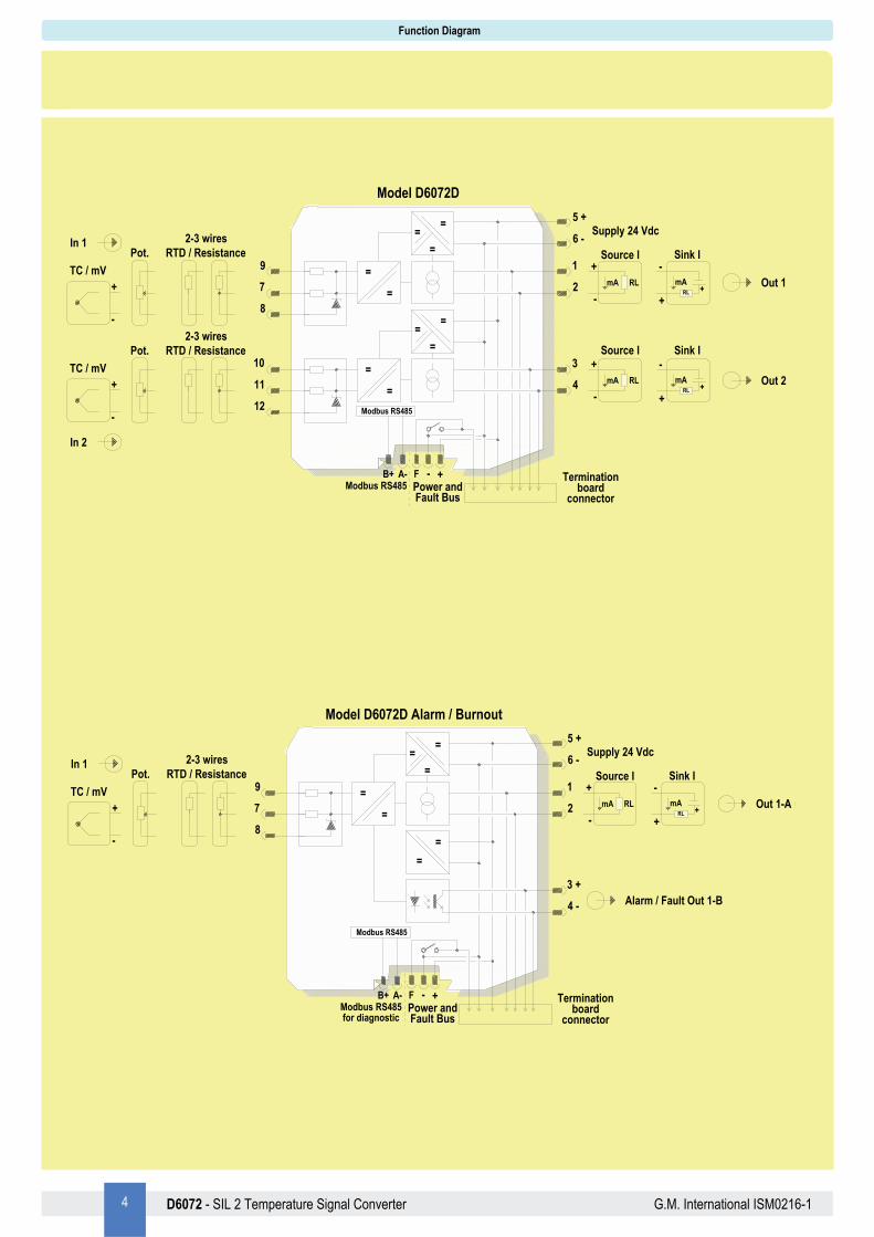
Model D6072D Alarm / Burnout
==
=
5 +
6 -
1
2
3
4
9
7
12
10
MODEL D5072D
=
=
=
=
RLmA
+
-
Source I
Out 1 (SIL 2)
RLmA
+
-
Source I
11
8
+- Terminationboard
connector
FPower andFault Bus
Supply 24 Vdc
Modbus RS485for diagnostic
A-B+
Modbus RS485
mA
Sink I
+
-
RL
Out 2 (SIL 2)mA
Sink I
+
-
RL
==
=
In 1
In 2
+
-
TC / mV
2-3 wiresRTD / ResistancePot.
+
-
TC / mV
2-3 wiresRTD / ResistancePot.
Model D6072D
5 D6072 - SIL 2 Temperature Signal Converter G.M. International ISM0216-1
Function Diagram
==
=
5 +
6 -
1
2
3
4
9
7
MODEL D5072D (Duplicator)
=
=RLmA
+
-
Source I
Out 1-A (SIL 2)
RLmA
+
-
Source I
8
+- Terminationboard
connector
FPower andFault Bus
Supply 24 Vdc
Modbus RS485for diagnostic
A-B+
Modbus RS485
mA
Sink I
+
-
RL
Out 1-B (SIL 2)mA
Sink I
+
-
RL
=
=
In 1
+
-
TC / mV
2-3 wiresRTD / ResistancePot.
==
=
5 +
6 -
1
2
3
4
9
7
12
10
=
=
=
=
RLmA
+
-
Source I
Out 1 (SIL 2)
RLmA
+
-
Source I
11
8
+- Terminationboard
connector
FPower andFault Bus
Supply 24 Vdc
Modbus RS485for diagnostic
A-B+
Modbus RS485
mA
Sink I
+
-
RL
Out 2 (SIL 2)mA
Sink I
+
-
RL
==
=
In 1
RTD forCold Junction Compensation
+
-
TCCopper wire
Copper wire
In 2
MODEL D5072D (with optional remote CJC)
==
=
5 +
6 -
1
2
9
10
MODEL D5072S
=
=7
8
+- Terminationboard
connector
FPower andFault Bus
Supply 24 Vdc
3 +
4 -
ModbusRS485
Modbus RS485for diagnostic
A-B+
RLmA
+
-
Source I
Out 1-A (SIL 2)mA
Sink I
+
-
RL
Alarm / Fault Out 1-B (SIL 2)
In
+
-
TC / mV
2-3-4 wiresRTD / ResistancePot.
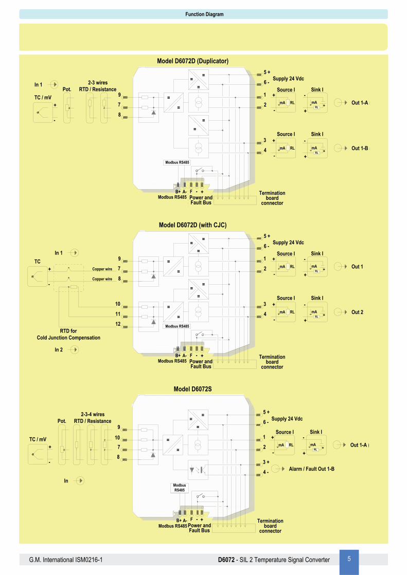
Model D6072D (with CJC)
Model D6072S
Model D6072D (Duplicator)
6 D6072 - SIL 2 Temperature Signal Converter G.M. International ISM0216-1
D6072 series must be installed, operated and maintained only by qualified personnel, in accordance to the relevant national/international installation standards. Failure to properly installation or use of the equipment may risk to damage the unit or severe personal injury. The unit cannot be repaired by the end user and must be returned to the manufacturer or his authorized representative. Any unauthorized modification must be avoided.
Warning
Operation
Each input channel of Temperature Signal Converter D6072 accepts a low level dc signal from millivolt, thermocouple or 2-3-4 wire RTD temperature or transmitting potentiometer sensor and converts, with isolation, the signal to a 4-20 mA floating output current to drive a load. Presence of supply power is displayed by a “POWER ON” green signaling LED; integrity of field sensor and connecting line can be monitored by a configurable burnout circuit which, if enabled, can drive output signal to upscale or downscale limit. Burnout condition is signaled by red front panel LED for each channel. D6072D module has double input and output channel, and can also be programmed to interface a single input and obtain dual output channel (duplicator) or configurable output channel (outputs can repeat the corresponding inputs or be proportional to the sum or difference of the two input process variables or with low/high selector function).
Installation
D6072 series are temperature signal converters housed in a plastic enclosure suitable for installation on T35 DIN-Rail according to EN50022, with or without Power Bus or on customized Termination Board. D6072 unit can be mounted with any orientation over the entire ambient temperature range. Electrical connection of conductors up to 2.5 mm² are accommodated by polarized plug-in removable screw terminal blocks which can be plugged in/out into a powered unit without suffering or causing any damage. The wiring cables have to be proportionate in base to the current and the length of the cable. On the section “Function Diagram” and enclosure side a block diagram identifies all connections. Identify the number of channels of the specific card (e.g. D6072S is a single channel model and D6072D is a dual channel model), the function and location of each connection terminal using the wiring diagram on the corresponding section, as an example (for each channel: thermocouple input, source current output): Connect 24 Vdc power supply positive at terminal “5” and negative at terminal “6”. For model D6072S connect positive output of channel 1 at terminal “1” and negative output at “2”. For model D6072D in addition to channel 1 connections above, connect positive output of channel 2 at terminal “3” and negative output at “4”. For channel 1, connect thermocouple positive extension wire at terminal “7”, negative and shield (if any) at terminal “8”. For channel 2, connect thermocouple positive extension wire at terminal “11”, negative and shield (if any) at terminal “12”. Make sure that compensating wires have the correct metal and thermal e.m.f. and are connected to the appropriate thermocouple terminal, note that a wrong compensating cable type or a swapped connection is not immediately apparent but introduces a misleading measurement error that appears as a temperature drift. Intrinsically Safe conductors must be identified and segregated from non I.S. and wired in accordance to the relevant national/international installation standards (e.g. EN/IEC60079-14 Electrical apparatus for explosive gas atmospheres - Part 14: Electrical installations in hazardous areas (other than mines)), make sure that conductors are well isolated from each other and do not produce any unintentional connection. Units must be protected against dirt, dust, extreme mechanical (e.g. vibration, impact and shock) and thermal stress, and casual contacts. If enclosure needs to be cleaned use only a cloth lightly moistened by a mixture of detergent in water. Any penetration of cleaning liquid must be avoided to prevent damage to the unit. Any unauthorized card modification must be avoided. According to EN61010, D6072 series must be connected to SELV or SELV-E supplies.
Start-up
Before powering the unit check that all wires are properly connected, particularly supply conductors and their polarity, input and output wires. Check conductors for exposed wires that could touch each other causing dangerous unwanted shorts. Turn on power, the “power on” green leds must be lit, output on each channel must be in accordance with the corresponding input signal value and input/output chosen transfer function. If possible change the sensor condition and check the corresponding Safe Area output.

7 D6072 - SIL 2 Temperature Signal Converter G.M. International ISM0216-1
Input specifications Input specifications:
Input Type Alpha Ohms Standards Min Span Accuracy Accuracy Range Maximum Range
RTD
Platinum
0.003850
50 IEC 60751 20 °C (36 °F)
±0.4 °C ±0.7 °F
-200 to 850 °C (-328 to 1562 °F)
-200 to 850 °C (-328 to 1562 °F)
100 IEC 60751
20 °C (36 °F)
±0.2 °C ±0.4 °F
-200 to 850 °C (-328 to 1562 °F)
-200 to 850 °C (-328 to 1562 °F)
200 IEC 60751 ±0.2 °C ±0.4 °F
-200 to 850 °C (-328 to 1562 °F)
-200 to 850 °C (-328 to 1562 °F)
300 IEC 60751 ±0.2 °C ±0.4 °F
-200 to 850 °C (-328 to 1562 °F)
-200 to 850 °C (-328 to 1562 °F)
400 IEC 60751 ±0.2 °C ±0.4 °F
-200 to 850 °C (-328 to 1562 °F)
-200 to 850 °C (-328 to 1562 °F)
500 IEC 60751 ±0.2 °C ±0.4 °F
-200 to 850 °C (-328 to 1562 °F)
-200 to 850 °C (-328 to 1562 °F)
1000 IEC 60751 ±0.2 °C ±0.4 °F
-200 to 850 °C (-328 to 1562 °F)
-200 to 850 °C (-328 to 1562 °F)
0.003916 100 ANSI 20 °C (36 °F)
±0.2 °C ±0.4 °F
-200 to 625 °C (-328 to 1157 °F)
-200 to 625 °C (-328 to 1157 °F)
0.003910
46 GOST 6651 20 °C (36 °F)
±0.4 °C ±0.7 °F
-200 to 650 °C (-328 to 1202 °F)
-200 to 650 °C (-328 to 1202 °F)
50 GOST 6651 ±0.4 °C ±0.7 °F
-200 to 650 °C (-328 to 1202 °F)
-200 to 650 °C (-328 to 1202 °F)
100 GOST 6651
20 °C (36 °F)
±0.2 °C ±0.4 °F
-200 to 650 °C (-328 to 1202 °F)
-200 to 650 °C (-328 to 1202 °F)
200 GOST 6651 ±0.2 °C ±0.4 °F
-200 to 650 °C (-328 to 1202 °F)
-200 to 650 °C (-328 to 1202 °F)
300 GOST 6651 ±0.2 °C ±0.4 °F
-200 to 650 °C (-328 to 1202 °F)
-200 to 650 °C (-328 to 1202 °F)
400 GOST 6651 ±0.2 °C ±0.4 °F
-200 to 650 °C (-328 to 1202 °F)
-200 to 650 °C (-328 to 1202 °F)
500 GOST 6651 ±0.2 °C ±0.4 °F
-200 to 650 °C (-328 to 1202 °F)
-200 to 650 °C (-328 to 1202 °F)
Nickel 0.00618 100 DIN 43760
20 °C (36 °F)
±0.2 °C ±0.4 °F
-60 to 180 °C (-76 to 356 °F)
-60 to 180 °C (-76 to 356 °F)
0.00672 120 DIN 43760 ±0.2 °C ±0.4 °F
-80 to 320 °C (-112 to 608 °F)
-80 to 320 °C (-112 to 608 °F)
Copper 0.00428
50 GOST 6651 20 °C (36 °F)
±0.4 °C ±0.7 °F
-50 to 200 °C (-58 to 392 °F)
-50 to 200 °C (-58 to 392 °F)
53 GOST 6651 20 °C (36 °F)
±0.4 °C ±0.7 °F
-50 to 200 °C (-58 to 392 °F)
-50 to 200 °C (-58 to 392 °F)
100 GOST 6651 20 °C (36 °F)
±0.2 °C ±0.4 °F
-50 to 200 °C (-58 to 392 °F)
-50 to 200 °C (-58 to 392 °F)
0.00427 9.035 --- 20 °C (36 °F)
±1.0 °C ±1.8 °F
-50 to 260 °C (-58 to 500 °F)
-50 to 260 °C (-58 to 500 °F)
Ohm Resistance 0 to 4000 --- 1 ohm ±0.4 ohm 0 to 4000 0 to 4000
Potentiometer 100 to 10000 --- 1 % ±0.1% 0 to 100% 0 to 100%
A1 --- GOST 8.585-2001 20 °C (36 °F)
±0.75 °C ±1.35 °F
25 to 2500 °C (77 to 4532 °F)
-10 to 2500 °C (14 to 4532 °F)
A2 --- GOST 8.585-2001 20 °C (36 °F)
±0.75 °C ±1.35 °F
25 to 1800 °C (77 to 3272 °F)
-10 to 1800 °C (14 to 3272 °F)
A3 --- GOST 8.585-2001 20 °C (36 °F)
±0.75 °C ±1.35 °F
25 to 1800 °C (77 to 3272 °F)
-10 to 1800 °C (14 to 3272 °F)
B --- IEC 60584 GOST 8.585-2001
100 °C (180 °F)
±0.75 °C ±1.35 °F
180 to 1800 °C (356 to 3272 °F)
-10 to 1800 °C (14 to 3272 °F)
E --- IEC 60584 GOST 8.585-2001
20 °C (36 °F)
±0.3 °C ±0.6 °F
-100 to 1000 °C (-148 to 1832 °F)
-250 to 1000 °C (-418 to 1832 °F)
J --- IEC 60584 GOST 8.585-2001
20 °C (36 °F)
±0.3 °C ±0.6 °F
-125 to 750 °C (-193 to 1382 °F)
-200 to 1200 °C (-328 to 2192 °F)
K --- IEC 60584 GOST 8.585-2001
20 °C (36 °F)
±0.3 °C ±0.6 °F
-125 to 1350 °C (-193 to 2462 °F)
-250 to 1350 °C (-418 to 2462 °F)
L --- DIN 43710 20 °C (36 °F)
±0.3 °C ±0.6 °F
-100 to 800 °C (-148 to 1472 °F)
-200 to 800 °C (-328 to 1472 °F)
LR --- GOST 8.585-2001 20 °C (36 °F)
±0.3 °C ±0.6 °F
-75 to 800 °C (-103 to 1472 °F)
-200 to 800 °C (-328 to 1472 °F)
N --- IEC 60584 GOST 8.585-2001
20 °C (36 °F)
±0.3 °C ±0.6 °F
-100 to 1300 °C (-148 to 2372 °F)
-250 to 1300 °C (-418 to 2372 °F)
R --- IEC 60584 GOST 8.585-2001
20 °C (36 °F)
±0.5 °C ±0.9 °F
75 to 1750 °C (167 to 3182 °F)
-50 to 1750 °C (-58 to 3182 °F)
S --- IEC 60584 GOST 8.585-2001
20 °C (36 °F)
±0.5 °C ±0.9 °F
75 to 1750 °C (167 to 3182 °F)
-50 to 1750 °C (-58 to 3182 °F)
T --- IEC 60584 GOST 8.585-2001
20 °C (36 °F)
±0.3 °C ±0.6 °F
-100 to 400 °C (-148 to 752 °F)
-250 to 400 °C (-418 to 752 °F)
U --- DIN 43710 20 °C (36 °F)
±0.3 °C ±0.6 °F
-100 to 400 °C (-148 to 752 °F)
-200 to 600 °C (-328 to 1112 °F)
mV DC --- --- 1 mV ±10 μV -50 to 80 mV -50 to 80 mV
TC
Notes: RTD/resistance accuracy shown in 4-wires configuration, in slow acquisition mode TC/mV Accuracy shown in slow acquisition mode
8 D6072 - SIL 2 Temperature Signal Converter G.M. International ISM0216-1
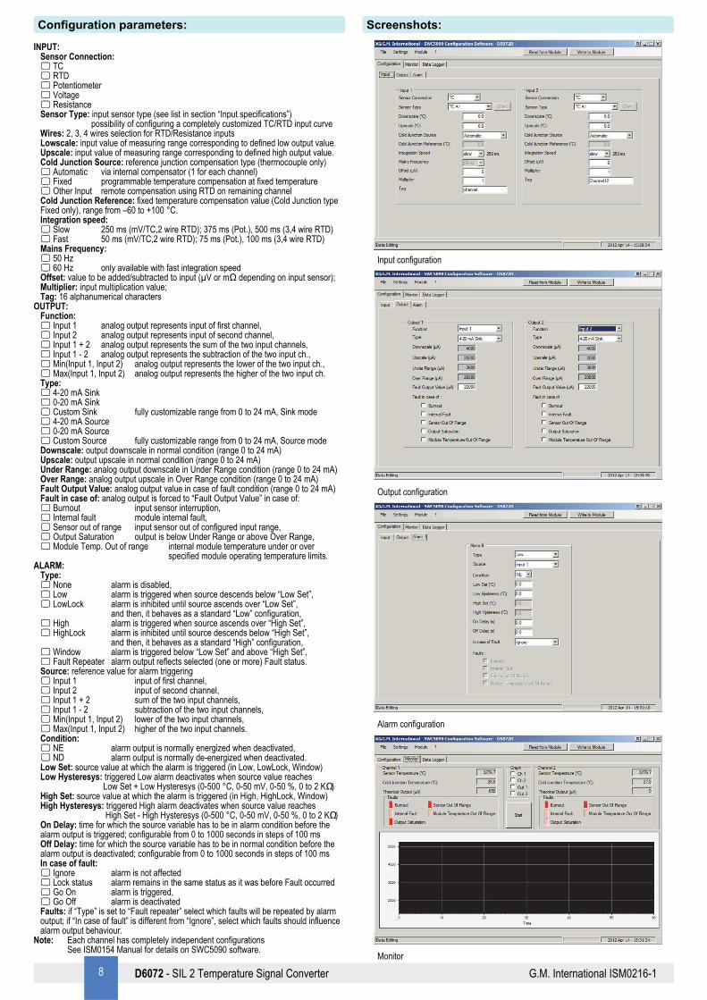
INPUT: Sensor Connection: TC RTD Potentiometer Voltage Resistance Sensor Type: input sensor type (see list in section “Input specifications”) possibility of configuring a completely customized TC/RTD input curve Wires: 2, 3, 4 wires selection for RTD/Resistance inputs Lowscale: input value of measuring range corresponding to defined low output value. Upscale: input value of measuring range corresponding to defined high output value. Cold Junction Source: reference junction compensation type (thermocouple only) Automatic via internal compensator (1 for each channel) Fixed programmable temperature compensation at fixed temperature Other Input remote compensation using RTD on remaining channel Cold Junction Reference: fixed temperature compensation value (Cold Junction type Fixed only), range from –60 to +100 °C. Integration speed: Slow 250 ms (mV/TC,2 wire RTD); 375 ms (Pot.), 500 ms (3,4 wire RTD) Fast 50 ms (mV/TC,2 wire RTD); 75 ms (Pot.), 100 ms (3,4 wire RTD) Mains Frequency: 50 Hz 60 Hz only available with fast integration speed Offset: value to be added/subtracted to input (µV or mΩ depending on input sensor); Multiplier: input multiplication value; Tag: 16 alphanumerical characters
OUTPUT: Function: Input 1 analog output represents input of first channel, Input 2 analog output represents input of second channel, Input 1 + 2 analog output represents the sum of the two input channels, Input 1 - 2 analog output represents the subtraction of the two input ch., Min(Input 1, Input 2) analog output represents the lower of the two input ch., Max(Input 1, Input 2) analog output represents the higher of the two input ch. Type: 4-20 mA Sink 0-20 mA Sink Custom Sink fully customizable range from 0 to 24 mA, Sink mode 4-20 mA Source 0-20 mA Source Custom Source fully customizable range from 0 to 24 mA, Source mode Downscale: output downscale in normal condition (range 0 to 24 mA) Upscale: output upscale in normal condition (range 0 to 24 mA) Under Range: analog output downscale in Under Range condition (range 0 to 24 mA) Over Range: analog output upscale in Over Range condition (range 0 to 24 mA) Fault Output Value: analog output value in case of fault condition (range 0 to 24 mA) Fault in case of: analog output is forced to “Fault Output Value” in case of: Burnout input sensor interruption, Internal fault module internal fault, Sensor out of range input sensor out of configured input range, Output Saturation output is below Under Range or above Over Range, Module Temp. Out of range internal module temperature under or over specified module operating temperature limits.
ALARM: Type: None alarm is disabled, Low alarm is triggered when source descends below “Low Set”, LowLock alarm is inhibited until source ascends over “Low Set”, and then, it behaves as a standard “Low” configuration, High alarm is triggered when source ascends over “High Set”, HighLock alarm is inhibited until source descends below “High Set”, and then, it behaves as a standard “High” configuration, Window alarm is triggered below “Low Set” and above “High Set”, Fault Repeater alarm output reflects selected (one or more) Fault status. Source: reference value for alarm triggering Input 1 input of first channel, Input 2 input of second channel, Input 1 + 2 sum of the two input channels, Input 1 - 2 subtraction of the two input channels, Min(Input 1, Input 2) lower of the two input channels, Max(Input 1, Input 2) higher of the two input channels. Condition: NE alarm output is normally energized when deactivated, ND alarm output is normally de-energized when deactivated. Low Set: source value at which the alarm is triggered (in Low, LowLock, Window) Low Hysteresys: triggered Low alarm deactivates when source value reaches Low Set + Low Hysteresys (0-500 °C, 0-50 mV, 0-50 %, 0 to 2 KΩ) High Set: source value at which the alarm is triggered (in High, HighLock, Window) High Hysteresys: triggered High alarm deactivates when source value reaches High Set - High Hysteresys (0-500 °C, 0-50 mV, 0-50 %, 0 to 2 KΩ) On Delay: time for which the source variable has to be in alarm condition before the alarm output is triggered; configurable from 0 to 1000 seconds in steps of 100 ms Off Delay: time for which the source variable has to be in normal condition before the alarm output is deactivated; configurable from 0 to 1000 seconds in steps of 100 ms In case of fault: Ignore alarm is not affected Lock status alarm remains in the same status as it was before Fault occurred Go On alarm is triggered, Go Off alarm is deactivated Faults: if “Type” is set to “Fault repeater” select which faults will be repeated by alarm output; if “In case of fault” is different from “Ignore”, select which faults should influence alarm output behaviour.
Note: Each channel has completely independent configurations See ISM0154 Manual for details on SWC5090 software.
Input configuration
Output configuration
Alarm configuration
Monitor
Configuration parameters: Screenshots:
9 D6072 - SIL 2 Temperature Signal Converter G.M. International ISM0216-1
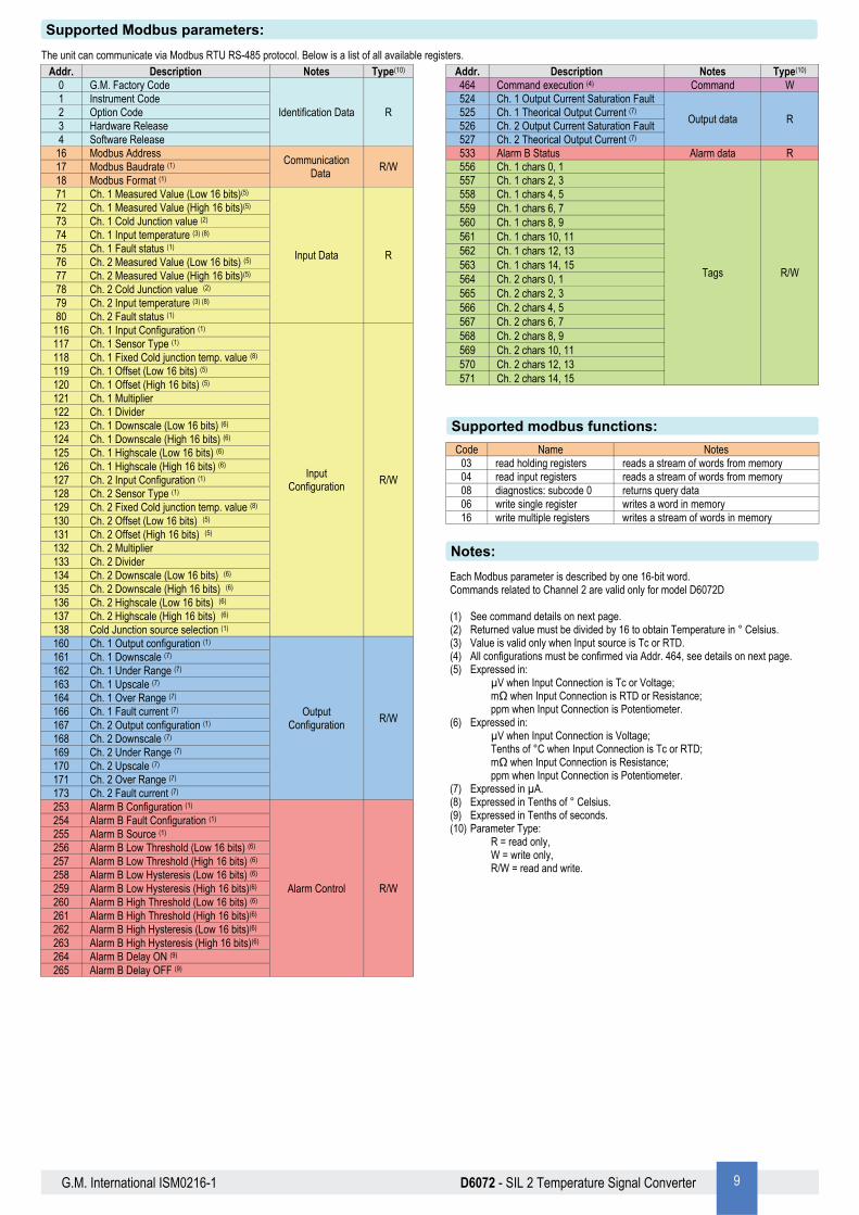
The unit can communicate via Modbus RTU RS-485 protocol. Below is a list of all available registers. Addr. Description Notes
0 G.M. Factory Code
Identification Data 1 Instrument Code 2 Option Code 3 Hardware Release 4 Software Release
16 Modbus Address Communication
Data 17 Modbus Baudrate (1) 18 Modbus Format (1) 71 Ch. 1 Measured Value (Low 16 bits)(5)
Input Data
72 Ch. 1 Measured Value (High 16 bits)(5) 73 Ch. 1 Cold Junction value (2) 74 Ch. 1 Input temperature (3) (8) 75 Ch. 1 Fault status (1) 76 Ch. 2 Measured Value (Low 16 bits) (5) 77 Ch. 2 Measured Value (High 16 bits)(5) 78 Ch. 2 Cold Junction value (2) 79 Ch. 2 Input temperature (3) (8) 80 Ch. 2 Fault status (1)
116 Ch. 1 Input Configuration (1)
Input Configuration
117 Ch. 1 Sensor Type (1) 118 Ch. 1 Fixed Cold junction temp. value (8) 119 Ch. 1 Offset (Low 16 bits) (5) 120 Ch. 1 Offset (High 16 bits) (5) 121 Ch. 1 Multiplier 122 Ch. 1 Divider 123 Ch. 1 Downscale (Low 16 bits) (6) 124 Ch. 1 Downscale (High 16 bits) (6) 125 Ch. 1 Highscale (Low 16 bits) (6) 126 Ch. 1 Highscale (High 16 bits) (6) 127 Ch. 2 Input Configuration (1) 128 Ch. 2 Sensor Type (1) 129 Ch. 2 Fixed Cold junction temp. value (8) 130 Ch. 2 Offset (Low 16 bits) (5) 131 Ch. 2 Offset (High 16 bits) (5) 132 Ch. 2 Multiplier 133 Ch. 2 Divider 134 Ch. 2 Downscale (Low 16 bits) (6) 135 Ch. 2 Downscale (High 16 bits) (6) 136 Ch. 2 Highscale (Low 16 bits) (6) 137 Ch. 2 Highscale (High 16 bits) (6) 138 Cold Junction source selection (1) 160 Ch. 1 Output configuration (1)
Output Configuration
161 Ch. 1 Downscale (7) 162 Ch. 1 Under Range (7) 163 Ch. 1 Upscale (7) 164 Ch. 1 Over Range (7) 166 Ch. 1 Fault current (7) 167 Ch. 2 Output configuration (1) 168 Ch. 2 Downscale (7) 169 Ch. 2 Under Range (7) 170 Ch. 2 Upscale (7) 171 Ch. 2 Over Range (7) 173 Ch. 2 Fault current (7) 253 Alarm B Configuration (1)
Alarm Control
254 Alarm B Fault Configuration (1) 255 Alarm B Source (1) 256 Alarm B Low Threshold (Low 16 bits) (6) 257 Alarm B Low Threshold (High 16 bits) (6) 258 Alarm B Low Hysteresis (Low 16 bits) (6) 259 Alarm B Low Hysteresis (High 16 bits)(6) 260 Alarm B High Threshold (Low 16 bits) (6) 261 Alarm B High Threshold (High 16 bits)(6) 262 Alarm B High Hysteresis (Low 16 bits)(6) 263 Alarm B High Hysteresis (High 16 bits)(6) 264 Alarm B Delay ON (9) 265 Alarm B Delay OFF (9)
Type(10)
R
R/W
R
R/W
R/W
R/W
Addr. Description Notes Type(10) 464 Command execution (4) Command W 524 Ch. 1 Output Current Saturation Fault
Output data R 525 Ch. 1 Theorical Output Current (7) 526 Ch. 2 Output Current Saturation Fault 527 Ch. 2 Theorical Output Current (7)
Alarm data R 533 Alarm B Status 556 Ch. 1 chars 0, 1
Tags R/W
557 Ch. 1 chars 2, 3 558 Ch. 1 chars 4, 5 559 Ch. 1 chars 6, 7 560 Ch. 1 chars 8, 9 561 Ch. 1 chars 10, 11 562 Ch. 1 chars 12, 13 563 Ch. 1 chars 14, 15 564 Ch. 2 chars 0, 1 565 Ch. 2 chars 2, 3 566 Ch. 2 chars 4, 5 567 Ch. 2 chars 6, 7 568 Ch. 2 chars 8, 9 569 Ch. 2 chars 10, 11 570 Ch. 2 chars 12, 13 571 Ch. 2 chars 14, 15
Supported Modbus parameters:
Each Modbus parameter is described by one 16-bit word. Commands related to Channel 2 are valid only for model D6072D (1) See command details on next page. (2) Returned value must be divided by 16 to obtain Temperature in ° Celsius. (3) Value is valid only when Input source is Tc or RTD. (4) All configurations must be confirmed via Addr. 464, see details on next page. (5) Expressed in:
µV when Input Connection is Tc or Voltage; mΩ when Input Connection is RTD or Resistance; ppm when Input Connection is Potentiometer.
(6) Expressed in: µV when Input Connection is Voltage; Tenths of °C when Input Connection is Tc or RTD; mΩ when Input Connection is Resistance; ppm when Input Connection is Potentiometer.
(7) Expressed in µA. (8) Expressed in Tenths of ° Celsius. (9) Expressed in Tenths of seconds. (10) Parameter Type:
R = read only, W = write only, R/W = read and write.
Notes:
Supported modbus functions:
Code Name Notes 03 read holding registers reads a stream of words from memory 04 read input registers reads a stream of words from memory
06 write single register writes a word in memory 16 write multiple registers writes a stream of words in memory
08 diagnostics: subcode 0 returns query data

10 D6072 - SIL 2 Temperature Signal Converter G.M. International ISM0216-1
Index Baudrate 0 4800 1 9600 2 19200 3 38400 4 57600 5 115200
Address 17: Supported Modbus Baudrates
Address 18: Supported Modbus Formats High Byte Low Byte
Bit position 15 14 13 12 11 10 9 8 7 6 5 4 3 2 1 0
Termination resistance (1 = enabled)
Endianness 32 bit Data (0 = Little; 1 = Big)
Address 75 and 80: Input Fault status High Byte Low Byte
Bit position 15 14 13 12 11 10 9 8 7 6 5 4 3 2 1 0
Internal cold junction sensor fault
Input sensor Burnout
Input sensor out of range
Internal communication fault
Module temperature out of range
Address 116 and 127: Input Configuration High Byte Low Byte
Bit position 15 14 13 12 11 10 9 8 7 6 5 4 3 2 1 0
Sensor connection: 0 Tc / Voltage (only SW revision 0) 1 RTD / Resistance 2-wires 2 RTD / Resistance 3-Wires 3 RTD / Resistance 4-Wires 4 Potentiometer 5 Tc / Voltage (only SW revision ≥ 1)
Integration speed (0 = Slow; 1 = Fast)
Mains supply freq. (0 = 50 Hz; 1 = 60 Hz)
Modbus parameters details:
Address 117 and 128: Input Sensor Type High Byte Low Byte
Bit position 15 14 13 12 11 10 9 8 7 6 5 4 3 2 1 0
0 Tc A1 1 Tc A2 2 Tc A3 3 Tc B 4 Tc E 5 Tc J 6 Tc K 7 Tc L 8 Tc Lr 9 Tc N
10 Tc R 11 Tc S 12 Tc T 13 Tc U 14 Pt 50 (IEC) 15 Pt 100 (IEC) 16 Pt 200 (IEC) 17 Pt 300 (IEC) 18 Pt 400 (IEC) 19 Pt 500 (IEC)
20 Pt 1000 (IEC) 21 Pt 100 (ANSI) 22 Pt 46 (GOST) 23 Pt 50 (GOST) 24 Pt 100 (GOST) 25 Pt 200 (GOST) 26 Pt 300 (GOST) 27 Pt 400 (GOST) 28 Pt 500 (GOST) 29 Ni 100 (DIN)
30 Ni 120 (DIN) 31 Cu 53 (GOST) 32 Cu 50 (GOST) 33 Cu 100 (GOST) 34 Cu 9.035 35 Voltage 36 Resistance 37 Custom device 38 Potentiometer
Address 138: Cold Junction Source selection High Byte Low Byte
Bit position 15 14 13 12 11 10 9 8 7 6 5 4 3 2 1 0
Ch. 1 Automatic Internal CJC (SW rev. ≥ 1)
Ch. 2 Automatic Internal CJC (SW rev. ≥ 1)
Ch. 1 Cold Junction from RTD on Ch. 2
Ch. 2 Cold Junction from RTD on Ch. 1
Ch. 1 Fixed Cold Junction
Ch. 2 Fixed Cold Junction
Address 160 and 167: Output Configuration High Byte Low Byte
Bit position 15 14 13 12 11 10 9 8 7 6 5 4 3 2 1 0
Burnout
Internal CJC Fault
Sensor out of range
Output Saturation
Out of temp. range
Internal comm. fault
Output Source: 0 Input 1 1 Input 2 2 In 1 + In 2 3 In 1 - In 2 4 Min (In 1, In 2) 5 Max (In 1, In 2)
Out type: 0 Sink 1 Source
Supported Modbus Parity: 0 8 data bit, no parity, 1 stop bit 1 8 data bit, even parity, 1 stop bit 2 8 data bit, odd parity, 1 stop bit
Address 242 and 255: Alarm Source High Byte Low Byte
Bit position 15 14 13 12 11 10 9 8 7 6 5 4 3 2 1 0
Alarm source:
0 Input 1 1 Input 2 2 In 1 + In 2
3 In 1 - In 2 4 Min (In 1, In 2) 5 Max (In 1, In 2)
Address 240 and 253: Alarm Configuration High Byte Low Byte
Bit position 15 14 13 12 11 10 9 8 7 6 5 4 3 2 1 0
Alarm Type: 0 None 1 Low 2 Low Lock
3 High 4 High Lock 5 Window 6 Flt repeat
Alarm Condition: 0 NE 1 ND
Configuration: 0 Ignore 1 Flt Lock 2 To ON 3 To OFF
Address 241 and 254: Alarm Fault Configuration High Byte Low Byte
Bit position 15 14 13 12 11 10 9 8 7 6 5 4 3 2 1 0
Internal comm. fault
Out of temperature
Sensor out of range
Burnout
Internal CJC fault
Available sensor types (see also page 8):
1 Save Input/Output Configuration 2 Save Modbus configuration 8 Save Tags 9 Lock Alarms 10 Analog Output Sink/Source Switch
Address 464: Various commands High Byte Low Byte
Bit position 15 14 13 12 11 10 9 8 7 6 5 4 3 2 1 0
All bits ‘0’ for Automatic Internal CJC (SW rev.= 0)