simp ifying power systems
TRANSCRIPT

Power*Too s for Windows
Version 7.0
Enhancement List
simp ifyingPower Systems

Electrical Engineering SoftwareDAPPER® /ŶƚĞŐƌĂƚĞĚ EůĞĐƚƌŝ ĐĂů AŶĂůLJƐŝƐ ^ŽŌǁĂƌĞCŽŵƉƌĞŚĞŶƐŝ ǀĞ dŚ ƌĞĞ WŚĂƐĞ ĂŶĚ hŶďĂůĂŶĐĞĚ ^ŚŽƌ ƚͲCŝƌĐƵŝƚ ^ƚƵĚŝĞƐ͕ >ŽĂĚ &ůŽǁ ^ƚƵĚLJ͕ DĞŵĂŶĚ >ŽĂĚ ^ƚƵĚLJ͕ &ĞĞĚĞƌ ĂŶĚ dƌĂŶƐĨŽƌŵĞƌ ^ŝnjŝŶŐ ^ƚƵĚLJ͕/ŵƉĂĐƚ DŽƚŽƌ ^ƚĂƌƟŶŐ ƚ̂ƵĚLJ͕ĂŶĚ >ŽĂĚ ^
CAPTOR® dŝŵĞͲKǀĞƌĐƵƌƌĞ Ŷƚ CŽŽƌĚŝŶĂƟŽŶ'ƌĂƉŚŝĐĂů dŝŵĞͲKǀĞƌĐƵƌ ƌĞŶƚ CŽŽƌĚŝŶĂƟ /ŶƚĞŐƌĂƚĞĚ ǁŝƚŚ ŽŶĞ ůŝŶĞƐ͕ ƐŚŽƌƚͲĐŝ ƌĐƵŝƚ ŵŽĚƵůĞƐ͕ EƋƵŝƉŵĞŶƚ EǀĂůƵĂƟŽŶ͕ ĂŶĚ AƌĐ &CŽŵƉƌĞŚĞŶƐŝ ǀĞ ƉƌŽƚĞĐƟ ǀĞ ĚĞǀŝĐĞ ůŝďƌĂƌLJ͘
ARC FLASH EVALUATIONCĂůĐƵůĂƚĞƐ ƚŚĞ ŝŶĐŝĚĞ Ŷƚ ĞŶĞ ƌŐLJ ĂŶĚ ĂƌĐ ŇĂƐŚ ďŽƵŶĚĂƌLJ ĨŽƌ ĞĂĐŚ ďƵƐ ŝŶ ƚŚĞ ƐLJƐƚĞŵ d͘ƌŝƉ ƟŵĞƐ ĂƌĞ ĂƵƚŽŵĂƟĐĂůůLJ ĚĞƚĞƌŵŝŶĞĚ ĨƌŽŵ ƚŚĞ ƉƌŽƚĞĐƟǀĞ ĚĞǀŝĐĞƐĞƫŶŐƐ ĂŶĚ ĂƌĐŝŶŐ ĨĂƵůƚ ĐƵƌƌĞŶƚ ǀ /ŶĐŝĚĞ Ŷƚ ĞŶĞƌŐLJ ĂŶĚ ĂƌĐ ŇĂƐŚ ďŽƵŶĚĂƌŝĞƐ ĂƌĞ ĐĂůĐƵůĂƚĞĚ ďĂƐĞĚ ŽŶ ĂĐĐƵŵƵů ĂƚĞĚ ĨĂƵůƚ ǀ CůŽƚŚŝŶŐƌĞƋƵŝ ƌĞŵĞ ŶƚƐ ĂƌĞ ƐƉĞĐŝĮĞĚĨ ƌŽŵ Ă ƵƐĞƌͲĚĞĮŶĞĚ ĐůŽƚŚŝŶŐ ůŝďƌĂƌLJ͘ CůĞĂƌŝŶŐ ƟŵĞƐ ĐĂŶ ďĞ ƌĞĚƵĐĞĚ ďĂƐĞĚ ŽŶ ĐƵƌƌĞŶƚͲůŝŵŝƟŶŐ Đ CŽŵƉůŝĞƐ ǁŝƚŚK^,A͕ E&WA ϳϬE͕ EEC ĂŶĚ /EEE ϭϱϴϰ ƌĞƋƵŝƌĞŵĞ Ŷ 'ĞŶĞƌĂƚĞƐ ĐƵƐƚŽŵ ůĂďĞůƐ ĂŶĚ ǁŽƌŬ Ɖ AůƐŽ ĂǀĂŝůĂďůĞ ĂƐ AƌĐCĂůĐ͕ Ă ƐŝŵƉůŝĮĞĚ ƐƚĂŶĚͲalone Arc Flash calculator.
A_FAULT ANSI Short-Circuit StudydŚƌĞĞ WŚĂƐĞĂŶĚ hŶďĂůĂŶĐĞĚ ^ŚŽƌ ƚͲCŝƌĐƵŝƚ ďĂƐĞĚ ŽŶ ƚŚĞ AE^/ͬ/EEE Cϯϳ ^ƚĂŶĚĂƌ ^ĞƉĂ ƌĂƚĞ ƐŽůƵƟŽŶƐ ĨŽƌ ůŽǁ͕ŵĞĚŝ Ƶŵ ĂŶĚ ŚŝŐŚ ǀŽůƚĂŐĞ ƐLJƐƚĞŵƐ ĂŶĚĨŽƌ ƐLJŵŵĞƚƌŝĐĂů͕ ŵŽŵĞŶƚĂƌLJ ĂŶĚ ŝ ŶƚĞƌƌƵƉƟŶŐ ĐĂůĐƵůĂƟ
IEC_FAULT IEC Short-Circuit Study 909 or 363dŚƌĞĞ WŚĂƐĞ ĂŶĚ hŶďĂůĂŶĐĞĚ ^ŚŽƌƚͲCŝƌĐƵŝƚ ƚ̂ƵĚLJ ďĂƐĞĚ ŽŶ ƚŚĞ /EC ϲϬϵϬϵ Žƌ /EC ϲϭϯϲϯ ^ƚĂŶĚĂƌ
EQUIPMENT EVALUATION EƋƵŝƉŵĞŶƚ EǀĂůƵĂƟŽŶ ZĞƉŽƌƚAƵƚŽŵĂƟĐĂůůLJ ĐŽŵƉĂƌĞƐ ƐŚŽƌƚͲĐŝ ƌĐƵŝƚ ƌĂƟŶŐƐ͕ ǁŝƚŚƐƚĂŶĚ ƌĂƟŶŐ AƉƉůŝĞƐ ĚĞͲƌĂƟŶŐ ĂĚũƵ ƐƚŵĞŶƚƐ ĂŶĚ ƵƐĞƌ ĚĞ ŵĂƌŐŝŶĂůͬĨĂŝůĞĚ Đƌŝ ƚ/ŶĐůƵĚĞƐ ĞƌƌŽƌ ĐŚĞĐŬŝŶŐ ĨŽƌ ŝŶƉƵƚ ĚĂƚĂ ĂŶĚ ƚŽƉŽůŽŐLJ͘
TMS dƌĂŶƐŝĞŶƚ DŽƚŽƌ ^ƚĂƌƟŶŐ ^ŝŵƵůĂƟŽŶdŝŵĞͲďĂƐĞĚ ŵŽƚŽƌ ƐƚĂƌƟŶŐ ƐŝŵƵůĂƟŽŶ ǁŝƚŚ ŐƌĂƉŚŝĐĂů ŽƵƚƉƵƚ ͘/ŶĐůƵĚĞƐ ƌĞĚƵĐĞĚ ǀŽůƚĂŐĞ ĂŶĚ ĐĂƉĂĐŝƚŽƌ ƐƚĂƌƟŶŐ͕ ŐƌĂƉŚŝĐĂů ŵŽƚŽƌ ĂŶĚ ůŽĂĚ ŵŽĚĞů
HI_WAVE ,ĂƌŵŽŶŝĐ /ŶǀĞƐƟŐĂƟŽŶ ĂŶĚ &ŝů ƚĞƌ DĞƐŝŐŶ&ƌĞƋƵĞŶĐLJ ^ĐĂŶ͕ ,ĂƌŵŽŶŝĐ CƵƌƌĞŶƚ ͕ sŽůƚĂŐĞ Dŝ ƐƚŽƌƟŽŶ͕ ,ĂƌŵŽŶŝĐ >ŽĂĚ &ůŽǁ ĂŶĚ /ŶƚĞƌĂĐƟǀĞ &ŝůƚĞƌ
UNBALANCED/SINGLE PHASE STUDIES>ŽĂĚ ŇŽǁ͕ƐŚŽƌ ƚͲĐŝƌĐƵŝƚ ͕ĚĞŵĂŶĚ ůŽĂĚ ĂŶĂůLJƐŝƐ͕ ƐŝnjŝŶŐ͕ ĂŶĚ ůŽĂĚ Ɛ ZĞƉŽƌƚƐ ƐŝŶŐůĞͲƉŚĂƐĞ ůŽĂĚ Ɛ ĂŶĚ ƵŶďĂůĂŶĐĞĚ ŽƉĞ ƌĂƟŶŐ ĐŽŶĚŝƟŽŶƐ ŝŶĐůƵĚŝŶŐƉŚĂƐĞ ĂŶĚ ƐĞƋƵĞŶĐĞ ĐƵƌƌĞŶƚƐ ĂŶĚ ǀŽůƚĂŐ
I*SIM DLJŶĂŵŝĐ ŝ̂ŵƵůĂƟŽŶ ĂŶĚ dƌĂŶƐŝĞŶƚ ^ƚĂďŝůŝƚLJDLJŶĂŵŝĐ ZĞƐƉŽŶƐĞ ƚŽ WŽǁĞƌ ^LJƐƚĞŵ EůĞĐƚƌŽͲDĞĐŚĂŶŝ ĐĂů DŝƐƚƵƌďĂŶĐĞƐ͕ 'ĞŶĞ ƌĂƚŽƌ ŝ̂njŝŶŐ ĂŶĚ ^ƚĂďŝůŝƚLJ͕ &ůƵdž >ĞǀĞů DĂĐŚŝŶĞ ZĞƉƌĞƐĞ ŶƚĂƟ hƐĞƌDĞĮŶĞĚ 'ƌĂƉŚŝĐĂů DŽĚĞůƐ ĨŽƌ EdžĐŝƚĞƌ͕ dƵƌďŝŶĞ 'ŽǀĞƌŶŽƌ͕ W^^͕ ĂŶĚ ŽƚŚĞƌ ĐŽŶƚƌŽůůĞƌ
DISTRIBUTION RELIABILITY ZĞůŝĂďŝůŝƚLJ AŶĂůLJƐŝƐCĂůĐƵůĂƚĞƐ ƚŚĞ ƌĞůŝĂďŝůŝƚLJ ŝŶĚŝĐĞƐ ŽĨ ŝŶĚŝǀŝĚƵĂů ůŽĂĚ ƉŽŝŶ ƚƐ ĂŶĚ ƚŚĞ Ž ǀĞƌĂůů ĚŝƐƚƌŝďƵƟŽŶ ƐLJƐƚĞŵƐ ǁŝƚŚĞŝƚŚĞƌ ƌĂĚŝĂů Žƌ ůŽŽƉ ĐŽŶĮŐƵ ƌĂƟ /ŶĐůƵĚĞƐ >ŽĂĚWŽŝŶƚ Ddd&͕ &ĂŝůƵƌ zĞĂƌ͕ DddZ͕ AŶŶƵĂů KƵƚĂŐĞ͕ EEE^͕ ECK^d͕ ĂŶĚ ŽƚŚĞƌ / ƐƚͲƌĞů ĂƚĞĚ ĨĂĐƚŽƌƐ ĂŶĚ ĂŐŝŶŐ ĨĂĐƚŽƌƐ ĂƌĞ ŝŶĐůƵĚĞĚ ŝŶ ƚŚĞĂŶĂůLJƐŝƐ ƚŽ ĐŽŵƉĂ ƌĞ ĂůƚĞƌŶĂƟǀĞ
DC SYSTEMS ANALYSISBĂƩĞƌLJ ^ŝnjŝŶŐ͕ >ŽĂĚ &ůŽǁ͕Θ ^ŚŽƌƚ Cŝ ƌĐƵŝƚ AŶĂůLJƐŝ EǀĂůƵĂƚĞĂůů ůŽĂĚŝŶŐ ĐŽŶĚŝƟŽŶƐ ĨŽƌ DC ĚƵƚLJ ĐLJĐůĞ ůŽĂĚƐ ĂŶĚ AC ĞŵĞƌŐ /EEE Ɛƚϰϴϱ͕ ϭϭϭϱ͕ ϯϵϵ͕ ϵϰϲ͕ ĂŶĚ /EC Ɛƚ
GROUND MAT ^ƵďƐƚĂƟŽŶ 'ƌŽƵŶĚ 'ƌŝĚ DĞƐŝŐŶ ĂŶĚ AŶĂůLJƐŝƐKƉƟŵŝnjĞƐ ŐƌŝĚ ĚĞƐŝŐŶ ƵƐŝŶŐ ŐĞŶĞƌĂů ƉƵƌƉŽƐĞĮŶŝ ƚĞ ĞůĞŵĞ Ŷƚ ĂůŐŽƌŝƚŚŵ ĨŽƌ ƉŽƚĞŶƟĂů ĂŶĂůLJƐŝƐ ĂŶĚ ŐƌĂƉŚŝĐĂů ĨĂĐŝůŝƟĞƐ ƚŽ ǀĂůŝĚ ĂƚĞ ŐƌŽƵŶĚŝŶŐƐLJƐƚĞŵƐ ĞĸĐŝĞŶĐ LJ͘
/EE tŝƌŝŶŐ ƌĞŐƵůĂƟŽŶ ^ŝnjŝŶŐ/ŶƚĞŐƌĂƚĞƐ ƚŚĞƌƵůĞƐ ĂŶĚ Ě ĂƚĂ ƚĂďůĞƐ Ĩ ƌŽŵ ƚŚĞ /EE tŝƌŝŶŐ ZĞŐƵů ĂƟŽŶ ƚŽ ƐŝnjĞ ĐĂďůĞƐ ďĂƐĞĚ ŽŶ ƚŚĞ ĚĞƐŝŐ Ŷ ůŽĂĚƐ ŽĨ ƚŚĞ ƉŽǁĞƌ ƐLJƐƚĞŵ ͘ AƵƚŽŵĂƟĐĂůůLJ ƐĞůĞĐƚƚŚĞ ĐŽƌƌĞĐƚ ƚĂďůĞ ĨƌŽŵ ƚŚĞ /EE tŝƌŝŶŐ ZĞŐƵů ĂƟŽŶ ĂŶĚ ƉŝĐŬ ƚŚĞ ƉƌŽƉĞƌ ĐĂďůĞ Ɛŝnj
CABLE-3D^ŽůǀĞƐ ĐŽŵƉů Ğdž ƚŚƌĞĞͲĚŝŵĞŶƐŝŽŶĂů ĐĂďůĞ ƉƵůůŝŶŐ ƚĞŶƐŝŽŶ ĂŶĚ ƐŝĚĞǁĂůů ƉƌĞƐƐƵ ƌĞ ĐĂůĐƵů ĂƟ
PTW VIEWERZĞĂĚͲŽŶůLJǀĞƌƐŝŽŶ ŽĨ Wdt ĨŽƌ ĚŝƐƉů ĂLJŝŶŐ͕ ƉƌŝŶƟŶŐ͕ ĂŶĚ ĞdžƉŽƌƟŶŐ Ăůů ƐƚƵĚLJ ƌ ƌĞĂƚĞ Žƌ ĞdžƉĂŶĚ ŽŶĞͲůŝŶĞƐ ĂŶĚ ĂƉƉůLJ Ě ĂƚĂďůŽĐŬ sŝĞǁ dŝŵĞͲCƵƌƌĞŶƚCƵƌǀ sŝĞǁ ĂŶĚ ĐƌĞĂƚĞ ĐƵ ƐƚŽŵŝnjĞĚ AƌĐ &ůĂƐŚ >ĂďĞůƐ ĂŶĚ tŽƌŬ W
Arc Flash Evaluation – SKM Power*Tools for Windows Version 7.0 Enhancement List
1 | P a g e
Arc Flash Evaluation
1. NFPA 70E 2012 edition updates implemented. Updated Arc Flash Label Styles, PPE Table, andothers to be compliant with the new standard.
2. DC Arc Flash based on NFPA 70E 2012 Annex D.8.1.1.3. NESC 2012 edition updates implemented. Tables 410, 431, and 441 and incident energy
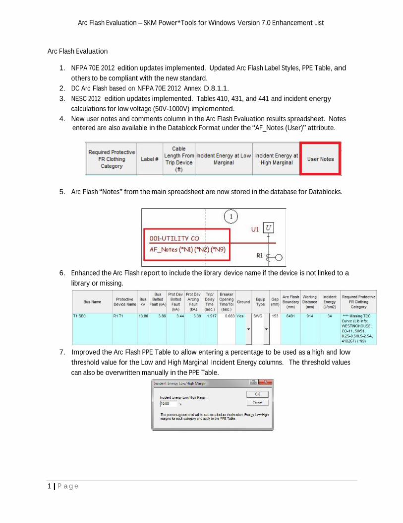
calculations for low voltage (50V-1000V) implemented.4. New user notes and comments column in the Arc Flash Evaluation results spreadsheet. Notes
entered are also available in the Datablock Format under the “AF_Notes (User)” attribute.
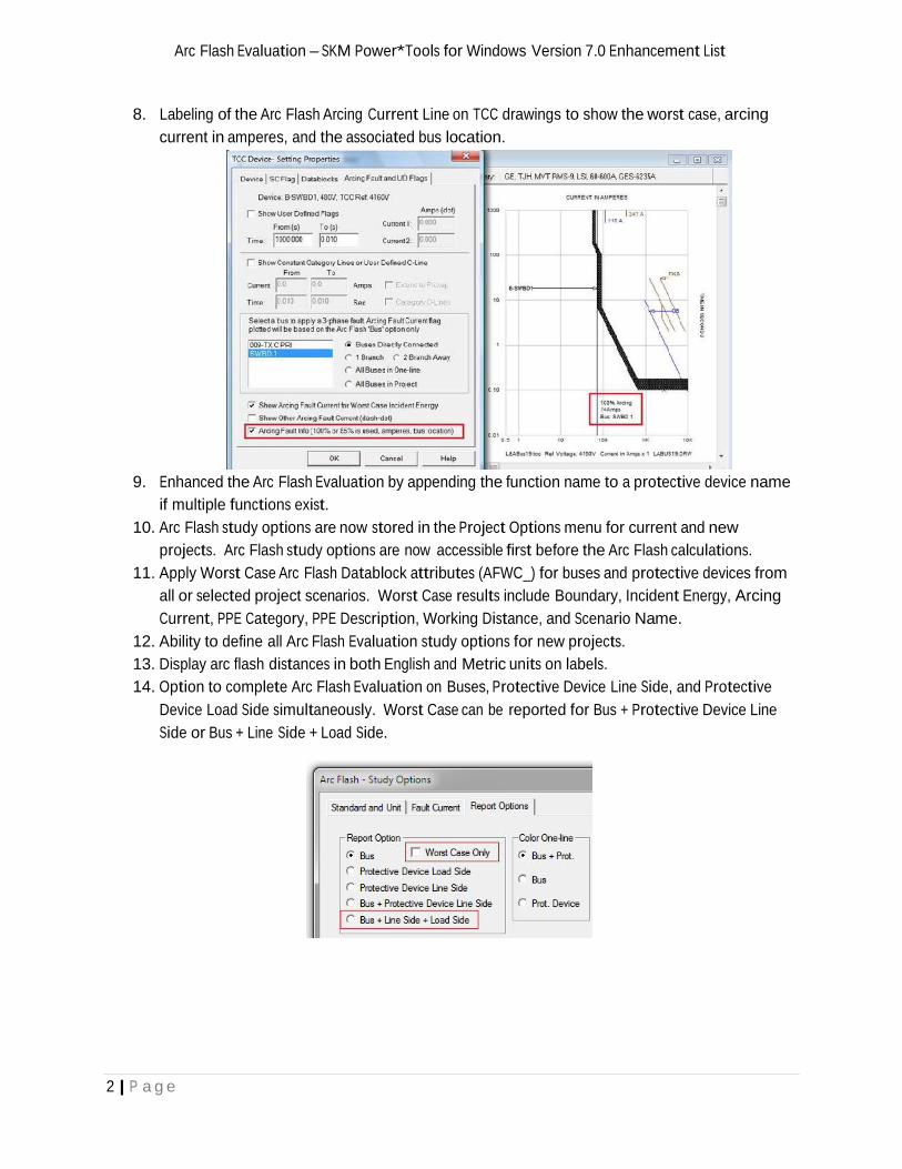
5. Arc Flash “Notes” from the main spreadsheet are now stored in the database for Datablocks.
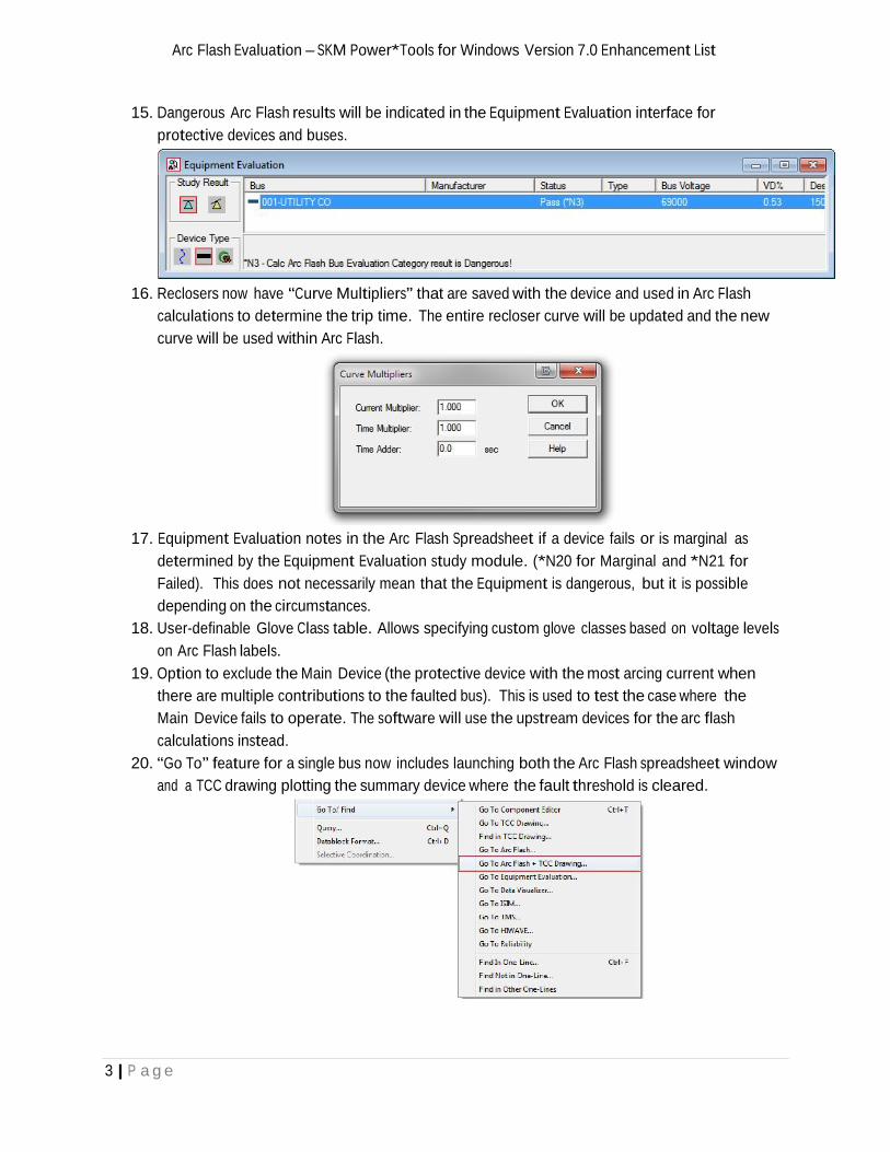
6. Enhanced the Arc Flash report to include the library device name if the device is not linked to alibrary or missing.
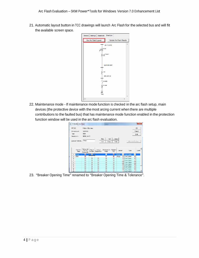
7. Improved the Arc Flash PPE Table to allow entering a percentage to be used as a high and lowthreshold value for the Low and High Marginal Incident Energy columns. The threshold valuescan also be overwritten manually in the PPE Table.
Arc Flash Evaluation – SKM Power*Tools for Windows Version 7.0 Enhancement List
2 | P a g e
8. Labeling of the Arc Flash Arcing Current Line on TCC drawings to show the worst case, arcingcurrent in amperes, and the associated bus location.
9. Enhanced the Arc Flash Evaluation by appending the function name to a protective device nameif multiple functions exist.
10. Arc Flash study options are now stored in the Project Options menu for current and newprojects. Arc Flash study options are now accessible first before the Arc Flash calculations.
11. Apply Worst Case Arc Flash Datablock attributes (AFWC_) for buses and protective devices fromall or selected project scenarios. Worst Case results include Boundary, Incident Energy, ArcingCurrent, PPE Category, PPE Description, Working Distance, and Scenario Name.
12. Ability to define all Arc Flash Evaluation study options for new projects.13. Display arc flash distances in both English and Metric units on labels.14. Option to complete Arc Flash Evaluation on Buses, Protective Device Line Side, and Protective
Device Load Side simultaneously. Worst Case can be reported for Bus + Protective Device LineSide or Bus + Line Side + Load Side.
Arc Flash Evaluation – SKM Power*Tools for Windows Version 7.0 Enhancement List
3 | P a g e
15. Dangerous Arc Flash results will be indicated in the Equipment Evaluation interface forprotective devices and buses.
16. Reclosers now have “Curve Multipliers” that are saved with the device and used in Arc Flashcalculations to determine the trip time. The entire recloser curve will be updated and the newcurve will be used within Arc Flash.
17. Equipment Evaluation notes in the Arc Flash Spreadsheet if a device fails or is marginal asdetermined by the Equipment Evaluation study module. (*N20 for Marginal and *N21 forFailed). This does not necessarily mean that the Equipment is dangerous, but it is possibledepending on the circumstances.
18. User-definable Glove Class table. Allows specifying custom glove classes based on voltage levelson Arc Flash labels.
19. Option to exclude the Main Device (the protective device with the most arcing current whenthere are multiple contributions to the faulted bus). This is used to test the case where theMain Device fails to operate. The software will use the upstream devices for the arc flashcalculations instead.
20. “Go To” feature for a single bus now includes launching both the Arc Flash spreadsheet windowand a TCC drawing plotting the summary device where the fault threshold is cleared.
Arc Flash Evaluation – SKM Power*Tools for Windows Version 7.0 Enhancement List
4 | P a g e
21. Automatic layout button in TCC drawings will launch Arc Flash for the selected bus and will fitthe available screen space.
22. Maintenance mode - If maintenance mode function is checked in the arc flash setup, maindevices (the protective device with the most arcing current when there are multiplecontributions to the faulted bus) that has maintenance mode function enabled in the protectionfunction window will be used in the arc flash evaluation.
23. “Breaker Opening Time” renamed to “Breaker Opening Time & Tolerance”.
5 | P a g e
CAPTOR – SKM Power*Tools for Windows Version 7.0 Enhancement List
CAPTOR
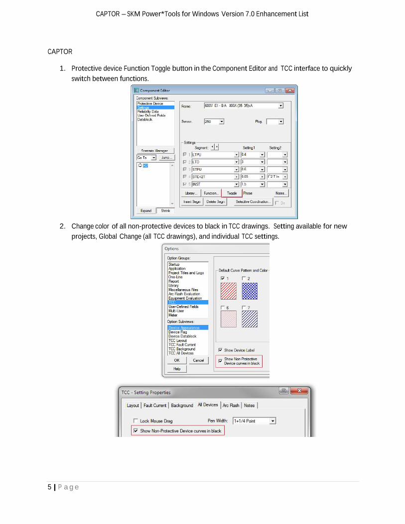
1. Protective device Function Toggle button in the Component Editor and TCC interface to quicklyswitch between functions.
2. Change color of all non-protective devices to black in TCC drawings. Setting available for newprojects, Global Change (all TCC drawings), and individual TCC settings.
6 | P a g e
CAPTOR – SKM Power*Tools for Windows Version 7.0 Enhancement List
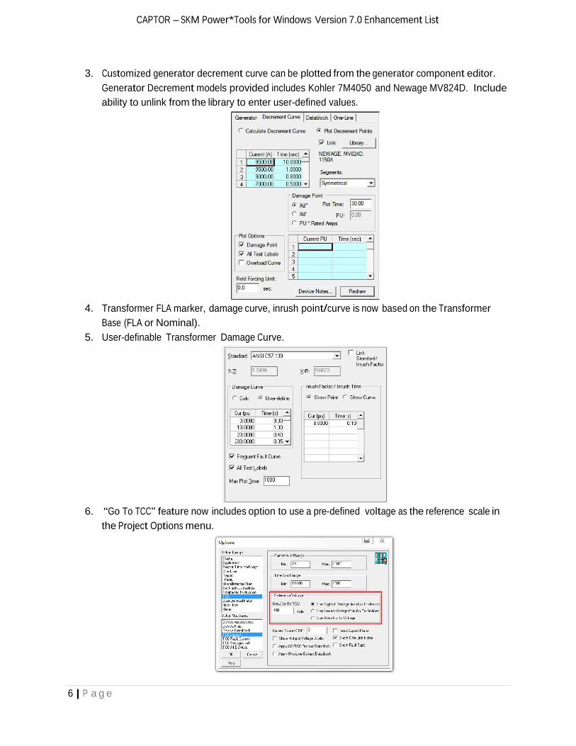
3. Customized generator decrement curve can be plotted from the generator component editor.Generator Decrement models provided includes Kohler 7M4050 and Newage MV824D. Includeability to unlink from the library to enter user-defined values.
4. Transformer FLA marker, damage curve, inrush point/curve is now based on the TransformerBase (FLA or Nominal).
5. User-definable Transformer Damage Curve.
6. “Go To TCC” feature now includes option to use a pre-defined voltage as the reference scale inthe Project Options menu.
7 | P a g e
CAPTOR – SKM Power*Tools for Windows Version 7.0 Enhancement List
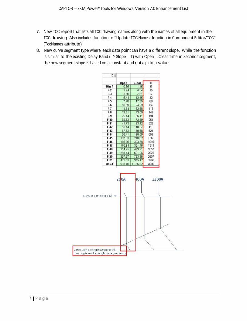
7. New TCC report that lists all TCC drawing names along with the names of all equipment in theTCC drawing. Also includes function to “Update TCC Names function in Component Editor/TCC”.(TccNames attribute)
8. New curve segment type where each data point can have a different slope. While the functionis similar to the existing Delay Band (I ^ Slope – T) with Open – Clear Time in Seconds segment,the new segment slope is based on a constant and not a pickup value.
8 | P a g e
CAPTOR – SKM Power*Tools for Windows Version 7.0 Enhancement List
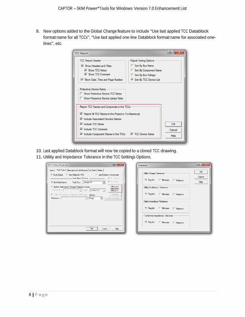
9. New options added to the Global Change feature to include “Use last applied TCC Datablockformat name for all TCCs”, “Use last applied one-line Datablock format name for associated one-lines”, etc.
10. Last applied Datablock format will now be copied to a cloned TCC drawing.11. Utility and Impedance Tolerance in the TCC Settings Options.
9 | P a g e
CAPTOR – SKM Power*Tools for Windows Version 7.0 Enhancement List
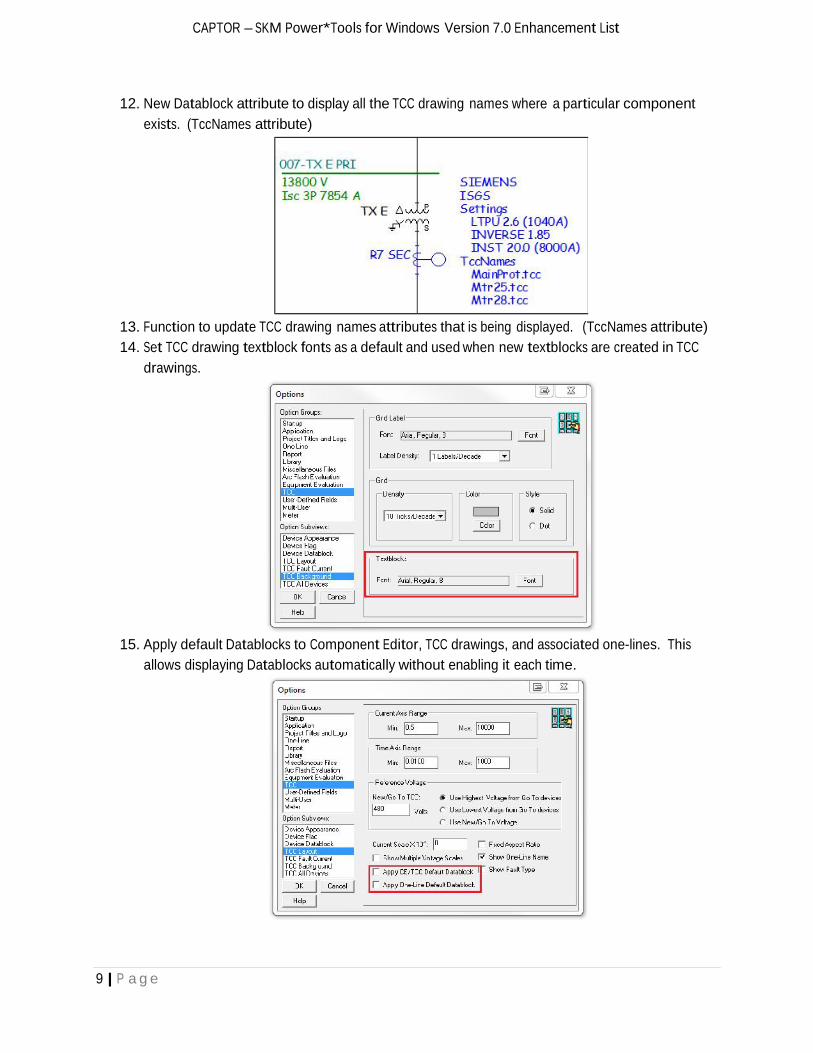
12. New Datablock attribute to display all the TCC drawing names where a particular componentexists. (TccNames attribute)
13. Function to update TCC drawing names attributes that is being displayed. (TccNames attribute)14. Set TCC drawing textblock fonts as a default and used when new textblocks are created in TCC
drawings.
15. Apply default Datablocks to Component Editor, TCC drawings, and associated one-lines. Thisallows displaying Datablocks automatically without enabling it each time.
10 | P a g e
CAPTOR – SKM Power*Tools for Windows Version 7.0 Enhancement List
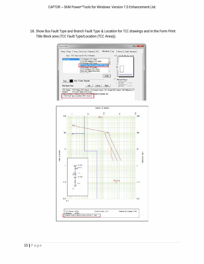
16. Show Bus Fault Type and Branch Fault Type & Location for TCC drawings and in the Form PrintTitle Block area (TCC Fault Type/Location (TCC Area)).
11 | P a g e
CAPTOR – SKM Power*Tools for Windows Version 7.0 Enhancement List
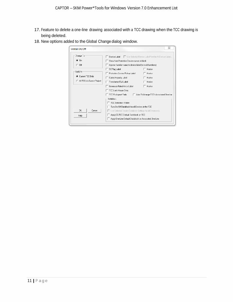
17. Feature to delete a one-line drawing associated with a TCC drawing when the TCC drawing isbeing deleted.
18. New options added to the Global Change dialog window.
12 | P a g e
General Modeling – SKM Power*Tools for Windows Version 7.0 Enhancement List
General Modeling
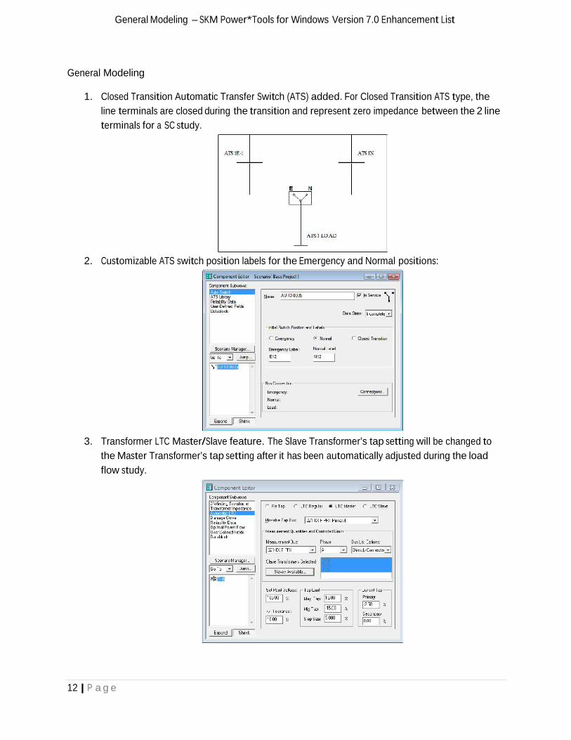
1. Closed Transition Automatic Transfer Switch (ATS) added. For Closed Transition ATS type, theline terminals are closed during the transition and represent zero impedance between the 2 lineterminals for a SC study.
2. Customizable ATS switch position labels for the Emergency and Normal positions:
3. Transformer LTC Master/Slave feature. The Slave Transformer’s tap setting will be changed tothe Master Transformer’s tap setting after it has been automatically adjusted during the loadflow study.
13 | P a g e
General Modeling – SKM Power*Tools for Windows Version 7.0 Enhancement List
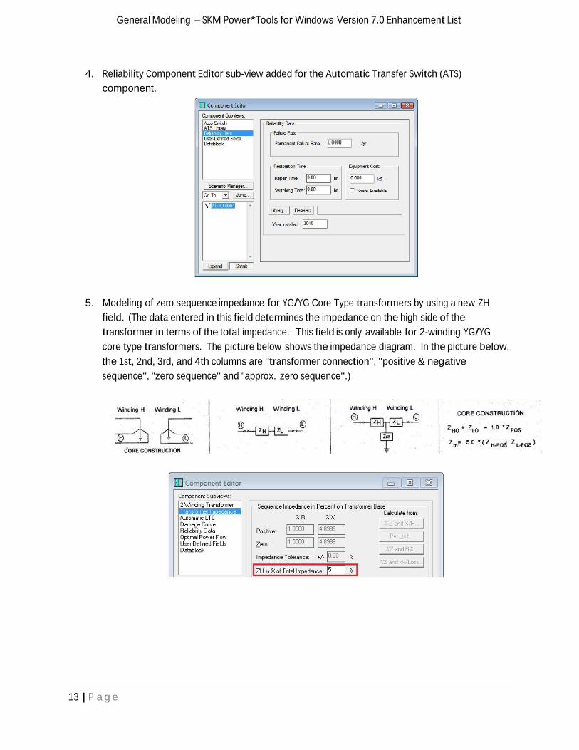
4. Reliability Component Editor sub-view added for the Automatic Transfer Switch (ATS)component.
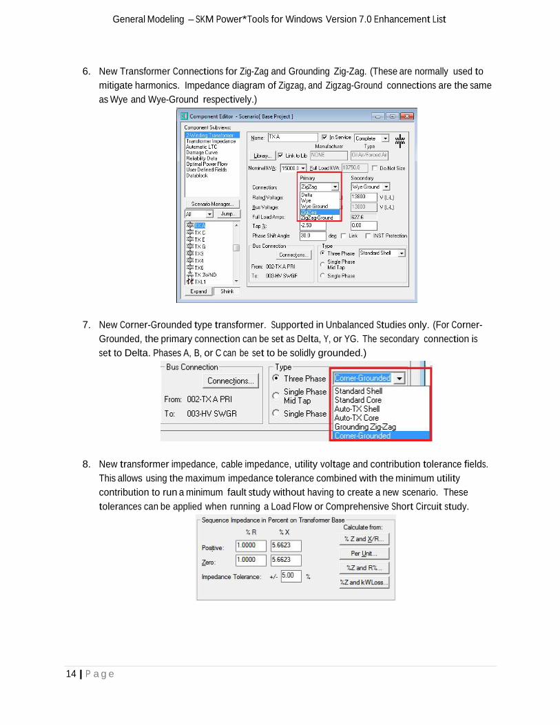
5. Modeling of zero sequence impedance for YG/YG Core Type transformers by using a new ZHfield. (The data entered in this field determines the impedance on the high side of thetransformer in terms of the total impedance. This field is only available for 2-winding YG/YGcore type transformers. The picture below shows the impedance diagram. In the picture below,the 1st, 2nd, 3rd, and 4th columns are "transformer connection", "positive & negativesequence", "zero sequence" and "approx. zero sequence".)
14 | P a g e
General Modeling – SKM Power*Tools for Windows Version 7.0 Enhancement List
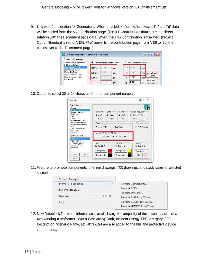
6. New Transformer Connections for Zig-Zag and Grounding Zig-Zag. (These are normally used tomitigate harmonics. Impedance diagram of Zigzag, and Zigzag-Ground connections are the sameas Wye and Wye-Ground respectively.)
7. New Corner-Grounded type transformer. Supported in Unbalanced Studies only. (For Corner-Grounded, the primary connection can be set as Delta, Y, or YG. The secondary connection isset to Delta. Phases A, B, or C can be set to be solidly grounded.)
8. New transformer impedance, cable impedance, utility voltage and contribution tolerance fields.This allows using the maximum impedance tolerance combined with the minimum utilitycontribution to run a minimum fault study without having to create a new scenario. Thesetolerances can be applied when running a Load Flow or Comprehensive Short Circuit study.
15 | P a g e
General Modeling – SKM Power*Tools for Windows Version 7.0 Enhancement List
9. Link with Contribution for Generators. When enabled, Xd"sat, Xd'sat, Xdsat, Td" and Td' datawill be copied from the SC Contribution page. (The IEC Contribution data has more directrelation with the Decrement page data. When the ANSI Contribution is displayed (ProjectOption Standard is set to ANSI), PTW converts the contribution page from ANSI to IEC, thencopies over to the Decrement page.)
10. Option to select 30 or 14 character limit for component names.
11. Feature to promote components, one-line drawings, TCC drawings, and study cases to selectedscenarios.
12. New Datablock Format attributes, such as displaying the ampacity of the secondary side of atwo-winding transformer. Worst Case Arcing Fault, Incident Energy, PPE Catergory, PPEDescription, Scenario Name, etc. attributes are also added to the bus and protective devicecomponents.
16 | P a g e
General Modeling – SKM Power*Tools for Windows Version 7.0 Enhancement List
13. Automatically display study result reports immediately after completing a study.
14. Show multiple function settings and CTs for Datablocks.
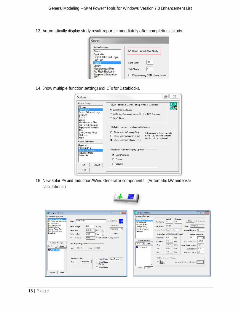
15. New Solar PV and Induction/Wind Generator components. (Automatic kW and kVarcalculations.)
17 | P a g e
General Modeling – SKM Power*Tools for Windows Version 7.0 Enhancement List
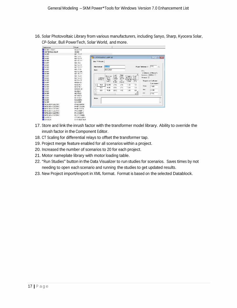
16. Solar Photovoltaic Library from various manufacturers, including Sanyo, Sharp, Kyocera Solar,CP-Solar, Bull PowerTech, Solar World, and more.
17. Store and link the inrush factor with the transformer model library. Ability to override theinrush factor in the Component Editor.
18. CT Scaling for differential relays to offset the transformer tap.19. Project merge feature enabled for all scenarios within a project.20. Increased the number of scenarios to 20 for each project.21. Motor nameplate library with motor loading table.22. “Run Studies” button in the Data Visualizer to run studies for scenarios. Saves times by not
needing to open each scenario and running the studies to get updated results.23. New Project import/export in XML format. Format is based on the selected Datablock.
18 | P a g e
Transient Motor Starting (TMS) – SKM Power*Tools for Windows Version 7.0 Enhancement List
Transient Motor Starting (TMS)
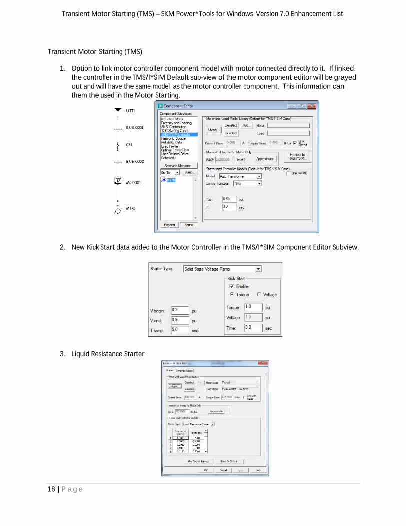
1. Option to link motor controller component model with motor connected directly to it. If linked,the controller in the TMS/I*SIM Default sub-view of the motor component editor will be grayedout and will have the same model as the motor controller component. This information canthem the used in the Motor Starting.
2. New Kick Start data added to the Motor Controller in the TMS/I*SIM Component Editor Subview.
3. Liquid Resistance Starter

19 | P a g e
Equipment Evaluation & HI_WAVE – SKM Power*Tools for Windows Version 7.0 Enhancement List
Equipment Evaluation
1. For comprehensive short circuit studies, 3p, SLG, LL, and LLG faults are now included in theevaluation. Previously, only 3p and SLG fault were considered.
2. Option to exclude pi-equivalent networks and tie-breakers from Equipment Evaluation.
HI_WAVE (Harmonic Analysis)
1. New selection in HIWAVE PCC Definition dialog for selecting IEEE 519 1992 and 1996 Draftstandards. All PCC options supported by both standards.
Here are the PCC Options:1. All utilities, generators, and harmonic source buses2. All utilities and generators buses3. Selected Buses4. All Buses

Accuracy
Simplicity
Results
Excellence
Taking Power Systems Analysis and Design
to New Heights
Since 1972, SKM Systems AnalysisInc. has been the market leader inpower systems analysis anddesign software. With the releaseof Power*Tools for WindowsVersion 7.0, SKM has reachednewer heights with the mostproductive software to bereleased in its 40 year history tothe professional engineeringcommunity.
New PTW software featuresaccelerate tasks, enhancereporting, increase equipmentlibraries, improve workflow, addnew study options and more tomeet challenging industrydemands.
SKM Systems Analysis, Inc.1 Pearl Street
Redondo Beach, CA 90277Phone: 1-800-500-4SKMFax: [email protected]@skm.comwww.skm.com