simulation of the seawater heat exchanger with helical baffles · pdf filesimulation of the...
TRANSCRIPT

SIMULATION OF THE SEAWATER HEAT
EXCHANGER WITH HELICAL BAFFLES
Qingnan Huang
Shanghai Jiao Tong University, China
Outlines
Background
Simulation Methods
• Property Calculation Method
• Algorithm Design
• Flow and Heat Transfer Model
• User Interface
Conclusions
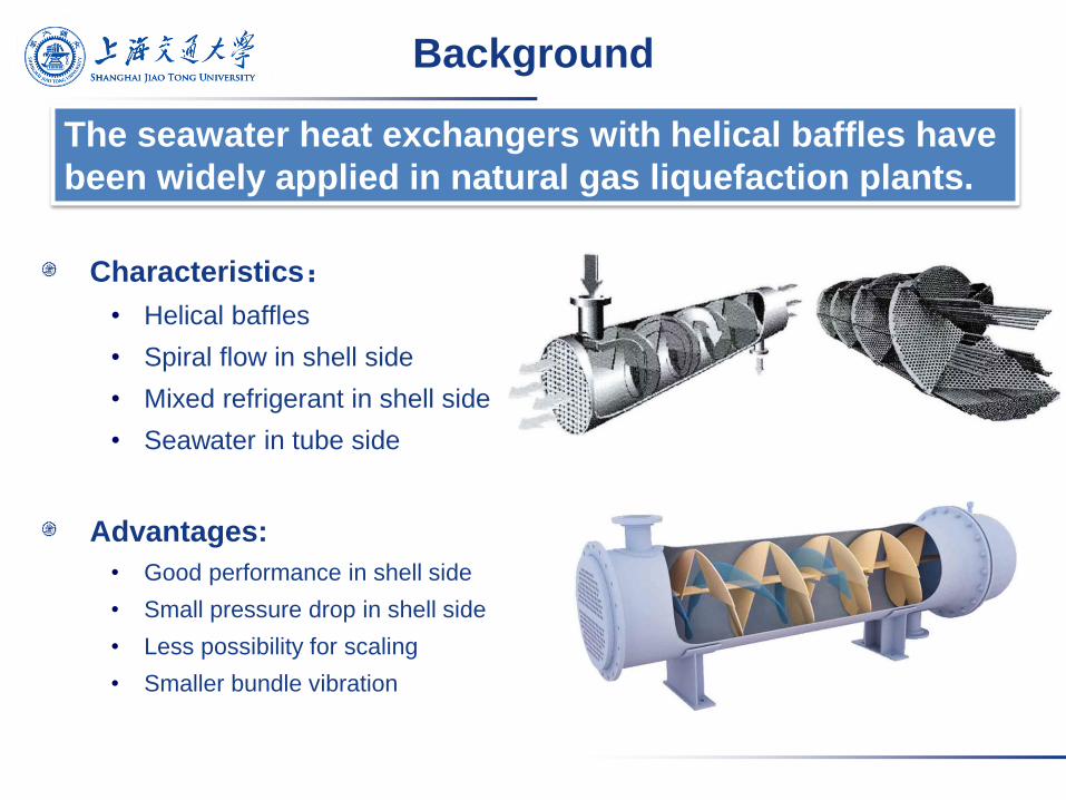
Characteristics:
• Helical baffles
• Spiral flow in shell side
• Mixed refrigerant in shell side
• Seawater in tube side
Advantages:
• Good performance in shell side
• Small pressure drop in shell side
• Less possibility for scaling
• Smaller bundle vibration
The seawater heat exchangers with helical baffles have
been widely applied in natural gas liquefaction plants.
Background
Background
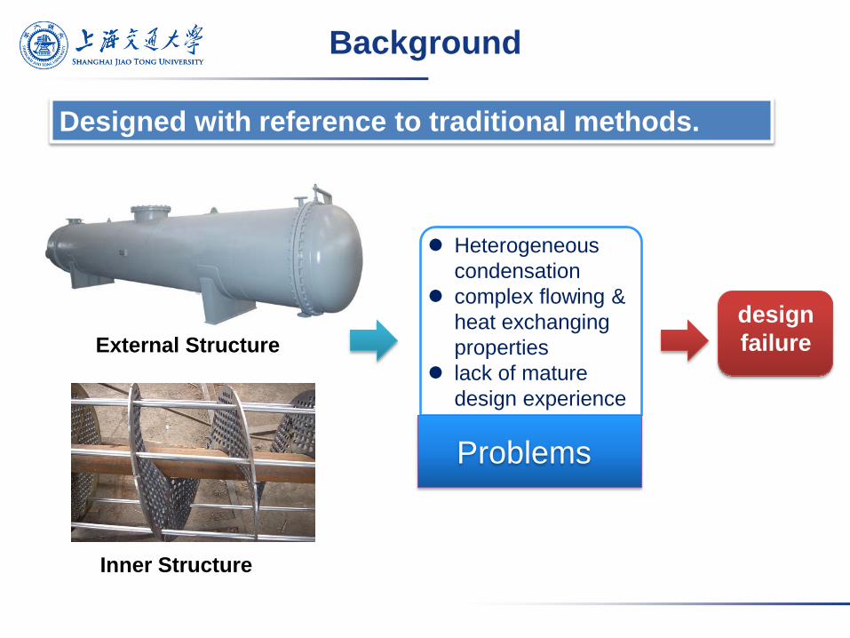
Problems
Heterogeneous
condensation
complex flowing &
heat exchanging
properties
lack of mature
design experience
Inner Structure
External Structure
design
failure
Designed with reference to traditional methods.
Background
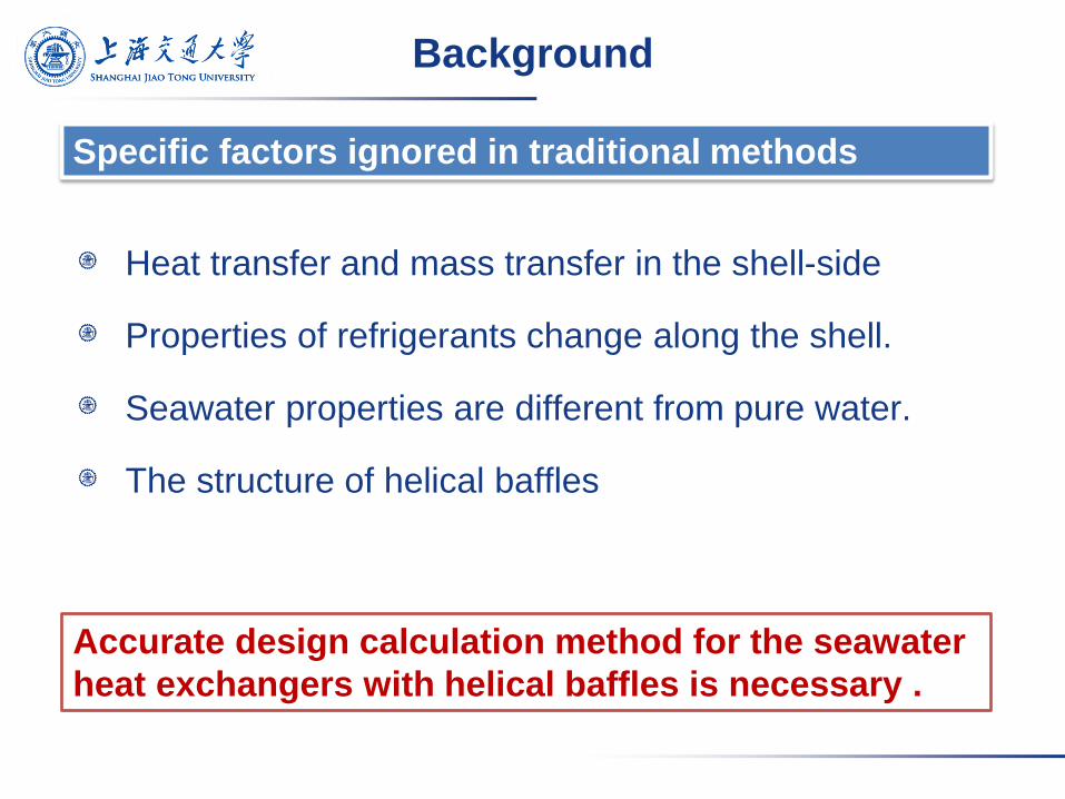
Specific factors ignored in traditional methods
Heat transfer and mass transfer in the shell-side
Properties of refrigerants change along the shell.
Seawater properties are different from pure water.
The structure of helical baffles
Accurate design calculation method for the seawater
heat exchangers with helical baffles is necessary .
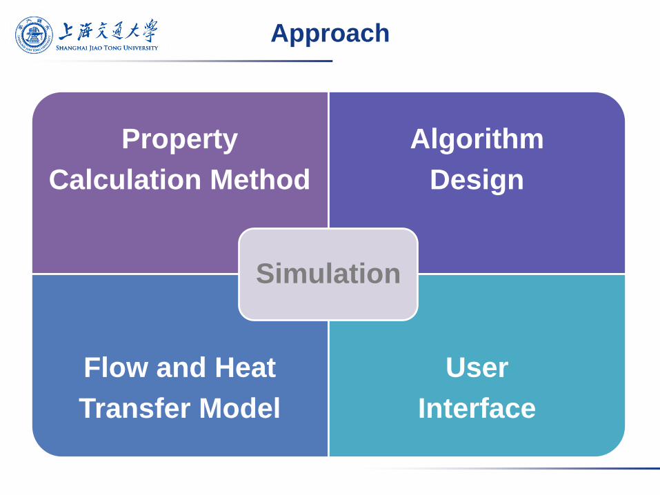
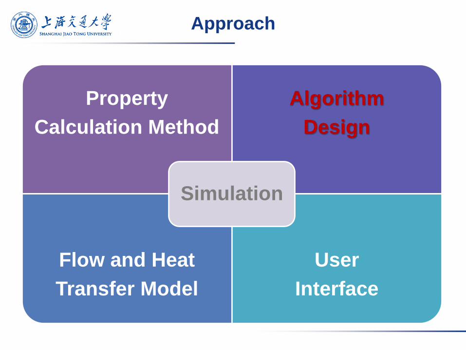
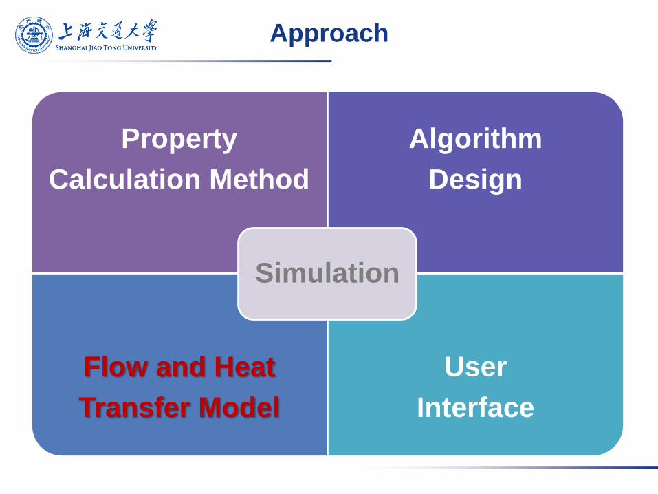
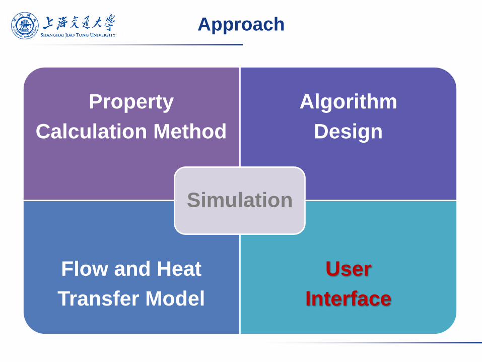
Approach
Property
Calculation Method
Algorithm
Design
Flow and Heat
Transfer Model
User
Interface
Simulation
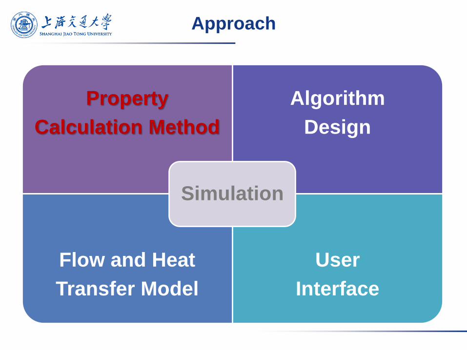
Approach
Property
Calculation Method
Algorithm
Design
Flow and Heat
Transfer Model
User
Interface
Simulation
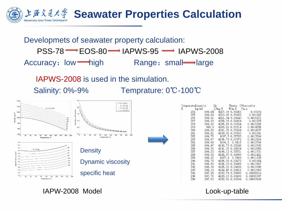
Seawater Properties Calculation
IAPWS-2008 is used in the simulation.
Salinity: 0%-9% Temprature: 0℃-100℃
Developmets of seawater property calculation:
PSS-78 EOS-80 IAPWS-95 IAPWS-2008
Accuracy:low high Range:small large
IAPW-2008 Model Look-up-table
Density
Dynamic viscosity
specific heat
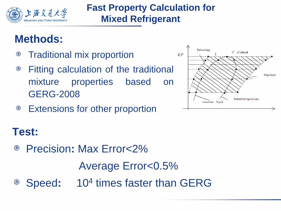
Fast Property Calculation for
Mixed Refrigerant
Methods:
Traditional mix proportion
Fitting calculation of the traditional
mixture properties based on
GERG-2008
Extensions for other proportion
Test:
Precision: Max Error<2%
Average Error<0.5%
Speed: 104 times faster than GERG
Approach
Property
Calculation Method
Algorithm
Design
Flow and Heat
Transfer Model
User
Interface
Simulation
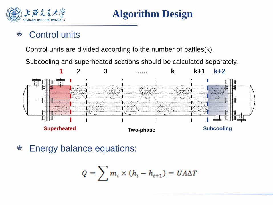
Algorithm Design
Control units
Energy balance equations:
Control units are divided according to the number of baffles(k).
Subcooling and superheated sections should be calculated separately.
Superheated Subcooling Two-phase
1 2 3 …... k k+1 k+2
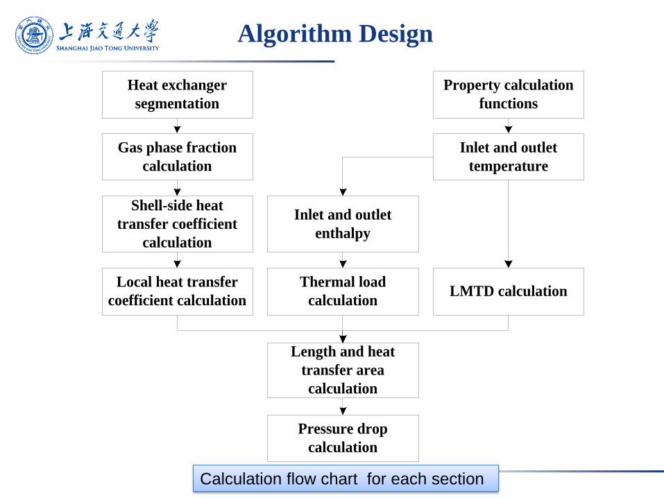
Algorithm Design
Gas phase fraction
calculation
Shell-side heat
transfer coefficient
calculation
Local heat transfer
coefficient calculation
Property calculation
functions
Inlet and outlet
temperature
Inlet and outlet
enthalpy
Thermal load
calculationLMTD calculation
Length and heat
transfer area
calculation
Pressure drop
calculation
Heat exchanger
segmentation
Calculation flow chart for each section
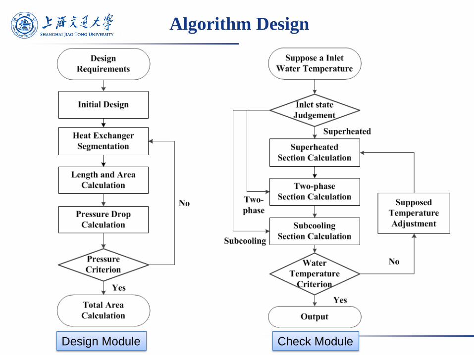
Algorithm Design
Design Module Check Module
Approach
Property
Calculation Method
Algorithm
Design
Flow and Heat
Transfer Model
User
Interface
Simulation
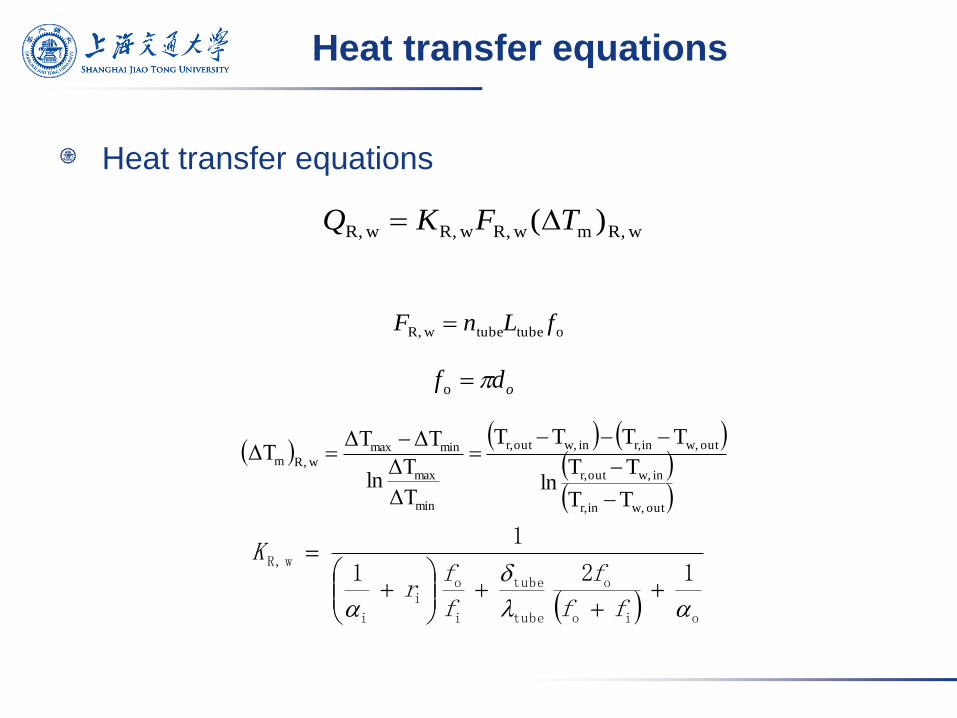
Heat transfer equations
wR,m wR, wR, wR, )( TFKQ
otubetube wR, fLnF
odf o
oio
o
tube
tube
i
oi
i
wR,121
1
ff
f
f
fr
K
out w,inr,
in w,outr,
out w,inr,in w,outr,
min
max
minmax
wR,m
TT
TTln
TTTT
ΔT
ΔTln
ΔTΔTΔT
Heat transfer equations
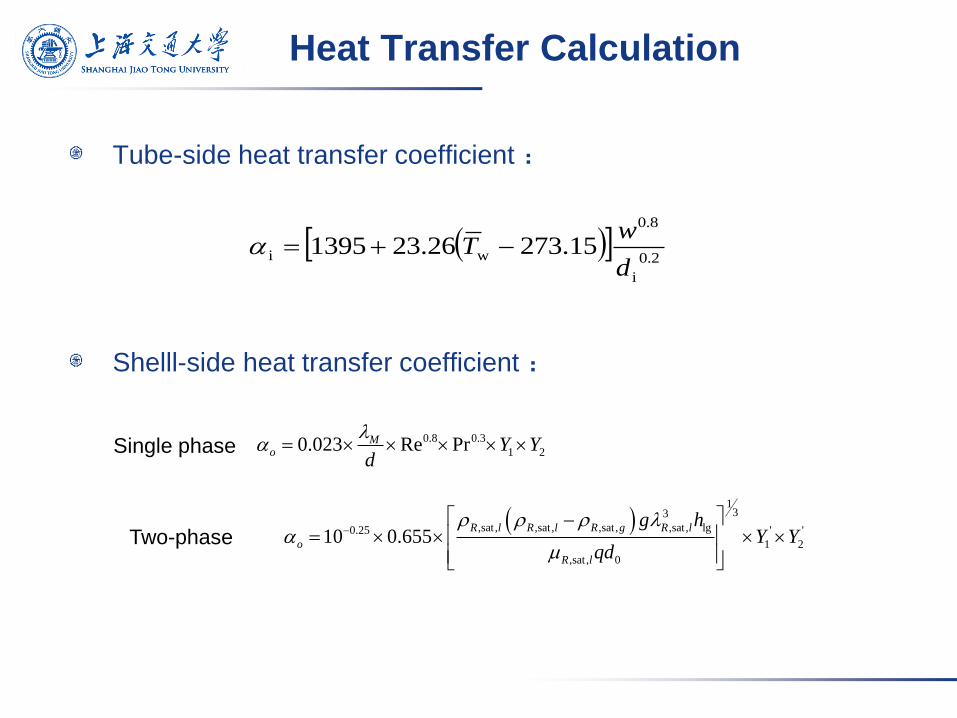
Tube-side heat transfer coefficient :
Shelll-side heat transfer coefficient :
Heat Transfer Calculation
2.0
i
8.0
wi 15.27326.231395d
wT
1
33
,sat , ,sat , ,sat , ,sat , lg0.25 ' '
1 2
,sat , 0
10 0.655R l R l R g R l
o
R l
g hY Y
qd
0.8 0.3
1 20.023 Re PrMo Y Y
d
Single phase
Two-phase
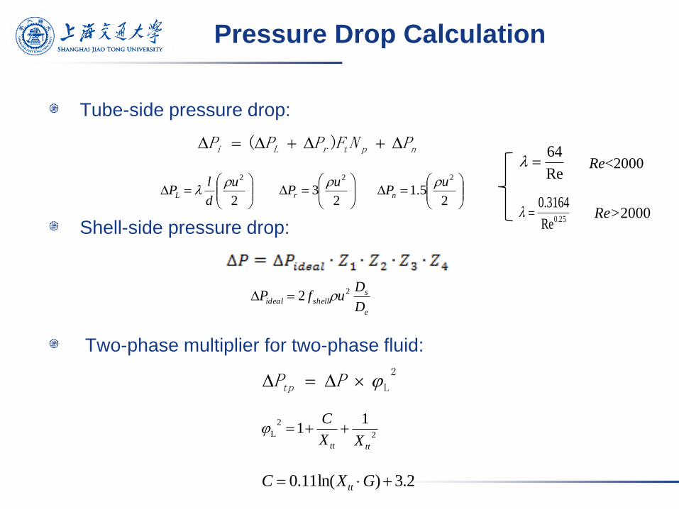
Tube-side pressure drop:
Shell-side pressure drop:
Two-phase multiplier for two-phase fluid:
Pressure Drop Calculation
nptrLi PNFPPP )(
2
2u
d
lPL
23
2uPr
25.1
2uPn
Re
64
25.0Re
3164.0
Re<2000
Re>2000
e
sshellideal
D
DufP 22
2
L PPtp
2
2
L
11
tttt XX
C
2.3)ln(11.0 GXC tt
Approach
Property
Calculation Method
Algorithm
Design
Flow and Heat
Transfer Model
User
Interface
Simulation
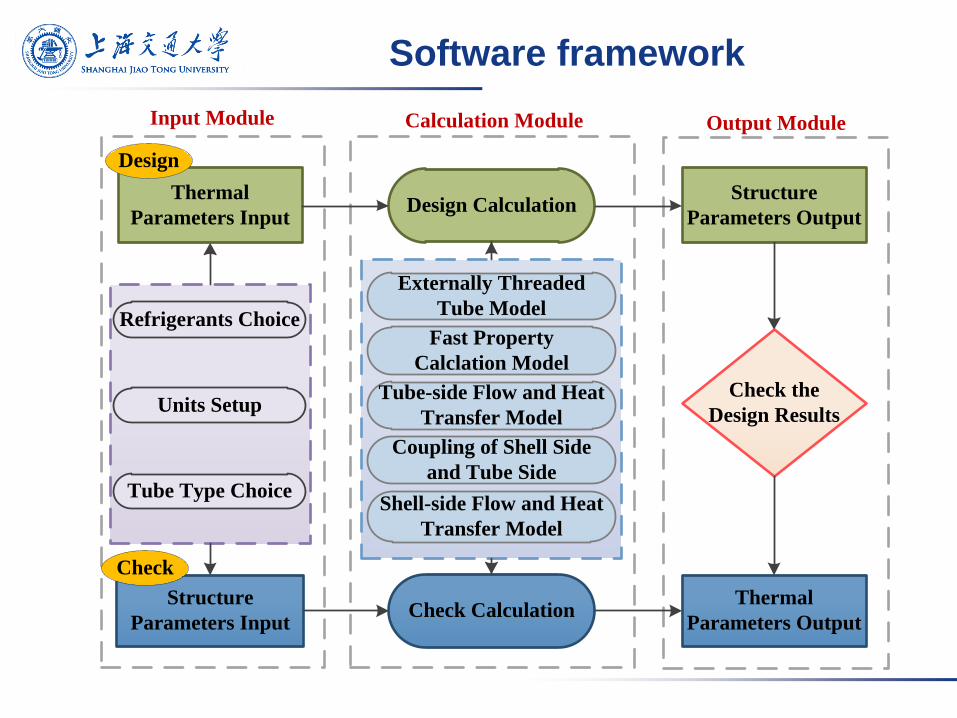
Software framework
Thermal
Parameters Input
Structure
Parameters Input
Design Calculation
Check Calculation
Structure
Parameters Output
Thermal
Parameters Output
Check the
Design Results
Refrigerants Choice
Units Setup
Tube Type Choice
Fast Property
Calclation Model
Tube-side Flow and Heat
Transfer Model
Shell-side Flow and Heat
Transfer Model
Externally Threaded
Tube Model
Coupling of Shell Side
and Tube Side
Design
Check
Input Module Calculation Module Output Module
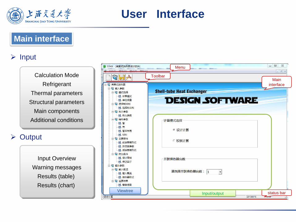
Toolbar
Menu
status bar
Main
interface
Viewtree Input/output
User Interface
Input
Output
Input Overview
Warning messages
Results (table)
Results (chart)
Calculation Mode
Refrigerant
Thermal parameters
Structural parameters
Main components
Additional conditions
Main interface
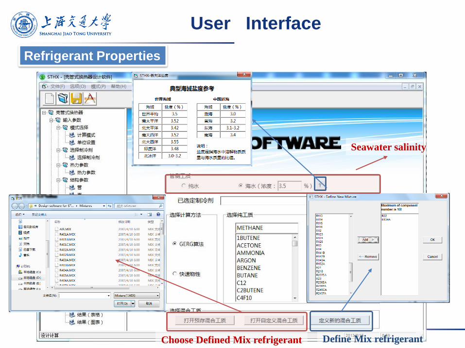
Choose Defined Mix refrigerant Define Mix refrigerant
Seawater salinity
Refrigerant Properties
User Interface
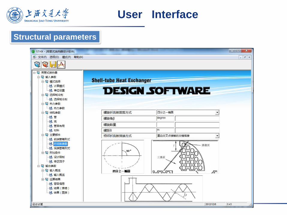
Structural parameters
User Interface
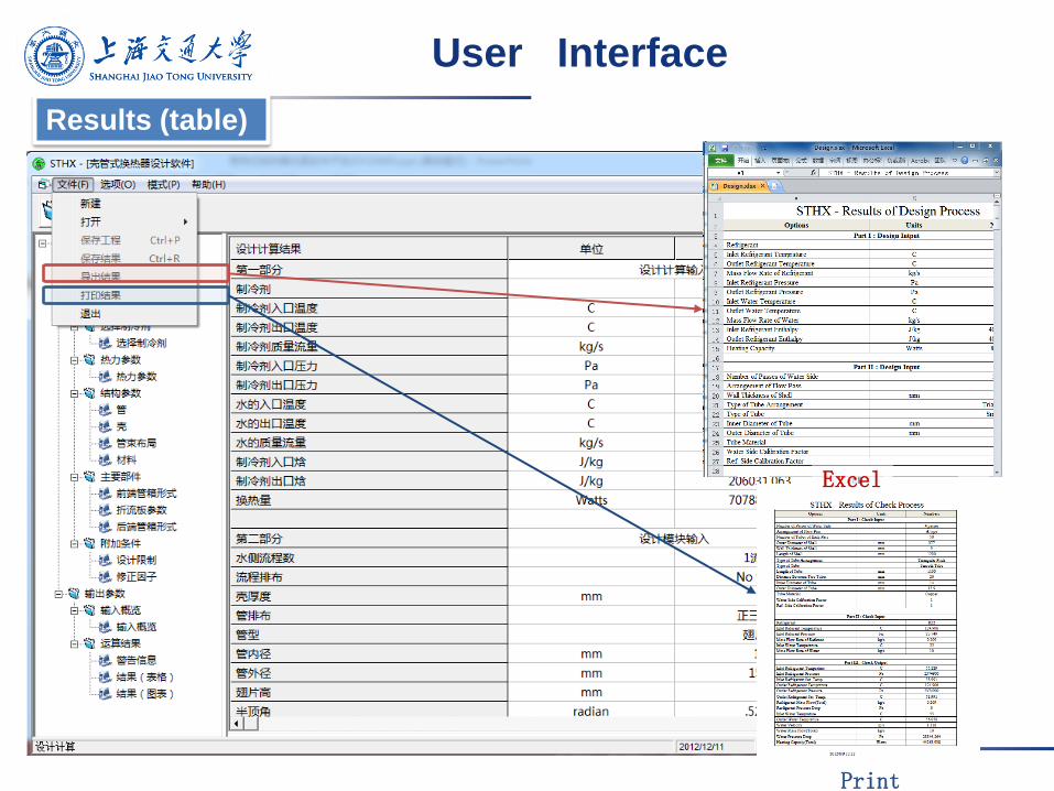
Excel
Results (table)
User Interface
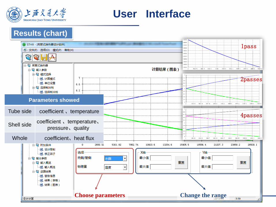
Choose parameters Change the range
1pass
2passes
4passes
Results (chart)
Parameters showed
Tube side coefficient 、temperature
Shell side coefficient 、temperature、
pressure、quality
Whole coefficient、heat flux
User Interface
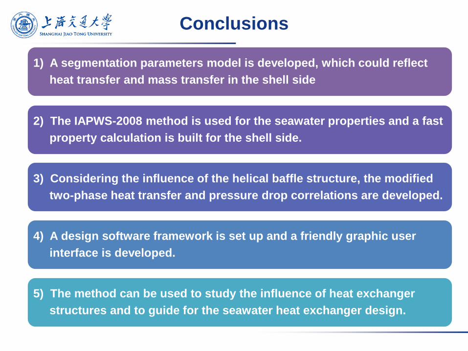
Conclusions
1) A segmentation parameters model is developed, which could reflect
heat transfer and mass transfer in the shell side
2) The IAPWS-2008 method is used for the seawater properties and a fast
property calculation is built for the shell side.
3) Considering the influence of the helical baffle structure, the modified
two-phase heat transfer and pressure drop correlations are developed.
4) A design software framework is set up and a friendly graphic user
interface is developed.
5) The method can be used to study the influence of heat exchanger
structures and to guide for the seawater heat exchanger design.

Thank you!