single fan vav ahu chilled water with options application ...lonmark.org/products/datasheets/sbt_vav...
TRANSCRIPT

Single Fan VAV AHU Chilled Water with Options
Application Data Sheet
Figure 1. Single Fan CHW VAV AHU with selectable hot water or electric heat with options
Features • LONMARK compliant with Discharge Air Controller Functional Profile (8610) • Economizer cycle driven by local dry bulb logic or network override • Minimum ventilation setting responds to air quality input for demand controlled ventilation • Multiple options for supply air temperature reset to optimize system performance • Interoperates with LonMark zone controllers to coordinate occupancy and air conditioning
functions • Adaptive control of outdoor air dampers responds quickly and stably in any season • PID control minimizes offset and maintains tighter set point control • Conforms to the LONMARK interoperability guidelines, enabling information sharing with LONMARK
products from other vendors.
Document No. 588-149 March 2003

Sequence of Operation
Occupied Control General The supply fan starts slowly and runs throughout the occupied mode. A PID control loop continually adjusts the fan capacity to maintain the duct static pressure at setpoint as loads vary in the zones. The duct pressure setpoint may be an adjustable constant, or may be varied automatically by another node to minimize energy consumption. Ventilation Control Ventilation (DCV) During occupied mode, the outdoor air damper opens to the design ventilation setting and stays open. When Demand Controlled Ventilation (DCV) is implemented, the ventilation setting may be automatically adjusted from internally in the Predator or by another node to a value appropriate for the demand. The Predator DCV function is adjustable, while the ventilation demand value comes from another node. The supply air temperature setpoint may be adjusted manually or varied according to an adjustable built-in reset function. Discharge Temperature Control
Hot Water Option When free cooling is available, the heating coil valve, outdoor air damper, and cooling coil valve modulate in sequence to maintain discharge air temperature setpoint. The outdoor air damper does not close beyond the current ventilation setting. When free cooling is unavailable, the outdoor air damper goes to the current ventilation setting; the heating coil valve and cooling coil valve modulate in sequence to maintain discharge air temperature setpoint. Staged Heat Option When free cooling is available, the heat stages, outdoors air damper, and cooling coil valve modulate in sequence to maintain discharge air temperature setpoint. The outdoor air damper does not close beyond the current ventilation setting. When free cooling is unavailable, the outdoor air damper goes to the current ventilation setting; the heat stages and cooling coil valve modulate in sequence to maintain discharge air temperature setpoint.
Unoccupied Control General During unoccupied periods, the air handler is normally off. The outdoor damper is closed and the cooling valve is closed. The optional hot water coil valve may be forced closed, or it may operate to maintain unit temperature above freezing. Optional staged heat stages are turned off. The Predator may run the air handler intermittently to provide heating or cooling in response to demand from the associated unoccupied zone controllers. Unoccupied Cooling Mode The air handler starts in response to a cool or pre-cool command from the network or measured zone temperature above the unoccupied setpoint. The Predator modulates the supply fan capacity to maintain measured duct pressure at the duct static pressure setpoint. If free cooling is not available, the outdoor air damper closes fully. Mechanical cooling may be locked out during unoccupied periods.
Page 2 of 11 Document No. 588-149

Document No. 588-149 Page 3 of 11
Unoccupied Heating Mode The air handler starts in response to a heat or warm-up command from the network or measured zone temperature below the unoccupied setpoint. The Predator modulates the supply fan capacity to maintain measured duct pressure at the duct static pressure setpoint. The hot water coil or staged heat is operated to maintain the supply air temperature at the heating setpoint. The cooling coil valve and the outdoor air damper are closed.
Safety Shutdown Low Temperature If a Low Temperature is detected the OA damper closes and the fan shuts off. The chilled water valve opens fully. The optional hot water coil valve opens fully; optional staged heat is turned off. The system may be configured to re-start automatically after the condition clears, or to remain shut down until a manual reset. Other Safeties Any number of other safety devices, such as smoke detectors or a high duct pressure switch, may be applied to shut the unit down. The Predator turns off the fan, closes the OA dampers and closes the coil valves. The Predator indicates an alarm condition over the network, and remains shut down until reset manually.
Off In this mode, the cooling or heating coil valve and OA damper are closed and the fan is off.
Temperature Control Sequence Diagrams
100% Open
DamperMinimum
0%
HeatingValve
CoolingValve
Air Conditioning Load
Outdoor AirDamper
The Predator sequences heating, cooling and outsideair as needed to meet air contidioning load.

Special Features
System Level Occupancy Control Occupancy for an air handler should be coordinated with occupancy for its respective zones. A site may employ more than one of the following interoperation mechanisms to accomplish system level coordination:
• The Predator Air Handler Controller may drive occupancy of the zones through bound network variables.
• The zone controllers may drive occupancy of the air handler so that it runs to meet their needs.
• Occupancy of the zones and air handler may both be driven in a coordinated way by another LonMark device.
The Predator responds to LonMark occupancy override (nviOccManCmd), allowing a building operator or technician to override the system from any LonMark compatible user interface.
The Predator responds to a LonMark compatible occupancy schedule input (nviOccSchedule). This allows the Predator to utilize the scheduling functions of other devices on the LonTalk Network.
The primary occupancy signal could also come from a time clock, wall switch, or occupancy sensor physically wired to one of the inputs of the Predator. This occupancy signal can then be shared with other controllers via the LonTalk Network.
Duct Pressure Reset To comply with ASHRAE Standard 90.1, Energy Efficiency for Commercial Buildings, the Predator supports automatic duct pressure reset by accepting a variable setpoint. The dynamic setpoint may calculated according to any algorithm in another device, and transmitted over the network.
Supply Temperature Reset The Predator can run an air handler as a classic constant-temperature VAV system, or it can dynamically adjust the supply temperature to adapt to loading conditions. The temperature may be reset using a built-in adjustable reset schedule, or calculated externally with a custom algorithm, and transmitted via the LonWorks network. The built-in reset schedules directly support the most popular approaches: reset based on space temperature, return temperature, outdoor temperature or a selected percentage demand signal from the zone controllers.
Demand Controlled Ventilation The Predator can control ventilation by the industry standard approach, using an adjustable minimum OA damper opening or by a demand-controlled strategy that adjusts the OA intake according to IAQ measurements in the occupied spaces. The DCV lets an HVAC designer build the system for the maximum anticipated ventilation requirements, but operate the system more economical ventilation rates when the actual demand is lower.
Night Heating and Cooling
Page 4 of 11 Document No. 588-149
The Predator supports several heating and cooling options for unoccupied periods. Using zone temperature data that either comes from the directly connected zone sensor or delivered over the network, the controller can cycle the air handler to meet heating and cooling needs of the zones. This function requires no intervention from a supervisory node. If some other start/stop criteria is required, another node may implement that logic and command the air handler on and off during the unoccupied period.

Document No. 588-149 Page 5 of 11
In cold climates, to prevent mechanical equipment freeze up, there is a need to keep the air handler warm even when the fan is off. The Predator can cycle or modulate an optional hot water valve to keep the mixed air temperature (or discharge temperature) within a desired range while the fan is off. The Predator can initiate a warm-up sequence for the zones. When the zone temperature and the outdoor temperature are both below adjustable limits and occupancy is due to start soon, the Predator switches to warm-up mode. It issues a network command for the zone controllers to put them in warm-up mode. The only inputs required are the zone temperature and the LonMark compatible schedule variable.
Adaptive Control of Outdoor Air Damper Past history has proven that tuning for economizer control loops poses problems. For example, when it is particularly cold outside, a small damper movement can cause a big change in the mixed air temperature. The control loop is likely to overshoot or even oscillate which can cause big problems in the air-handling unit. To prevent oscillation, it is necessary to tune the loop specifically for the cold-weather case. Then when warmer weather arrives, the cold-weather tuning leads to sloppy control and an ineffective air conditioning system. The Predator addresses this dilemma directly by automatically adjusting the economizer control loop tuning to suit the outdoor temperature. Without any attention or maintenance, the loop is always fast, stable and accurate, making the economizer truly economical.

Hardware Map – VAV AHU Termination Set Parameter Set in Element Name I/O Type Factory I/O Setting
StatTemp statTemp SPACE_TEMP StatSetpt statSetpt
TEMP IN_UNUSED
StatOvrd statOvrd DI STAT_SWITCH_DI In1 in1 DISCH_TEMP In2 in2
DI, TEMP RETRN_TEMP
In3 in3 DUCT_PRESS In4 in4 FAN_STATUS_DI In5 in5 LOW_TEMP_DI In6
inputs
in6
DI, PCT, TEMP
HI_PRESS_DI OutA1 outA1 SUP_FAN_CAP_AO OutA2 outA2 OA_DMPR_AO OutA3 outA3
AO
HEAT_COIL_AO OutD1 outD1 SUP_FAN_DO OutD2 outD2 OA_DAMPER_2POS_DO OutD3 outD3 DX_STAGE1_DO OutD4 outD4 DX_STAGE2_DO OutD5 outD5 DX_STAGE3_DO OutD6 outD6 DX_STAGE4_DO OutD7 outD7 HEAT_STAGE1_DO OutD8
outputs
outD8
DO, FLT_MTR
HEAT_STAGE2_DO
Table 1. Hardware Map
Page 6 of 11 Document No. 588-149

Document No. 588-149 Page 7 of 11
Wiring Diagram
Note: Route wiring from either the bottom opening when using a J-box or from the base sides as shown in the picture when flat or din rail mounting. The image above is for illustrative purposes only
Wiring Recommendations:
IN and AO: 20 to 22 AWG DO: 18 to 22 AWG Power: 16 to 18 AWG
LON Network: 22 AWG Level 4
Transformer Requirements:
Type: Class 2, 24 VAC, 50/60Hz
Figure 3. Predator Wiring Diagrams

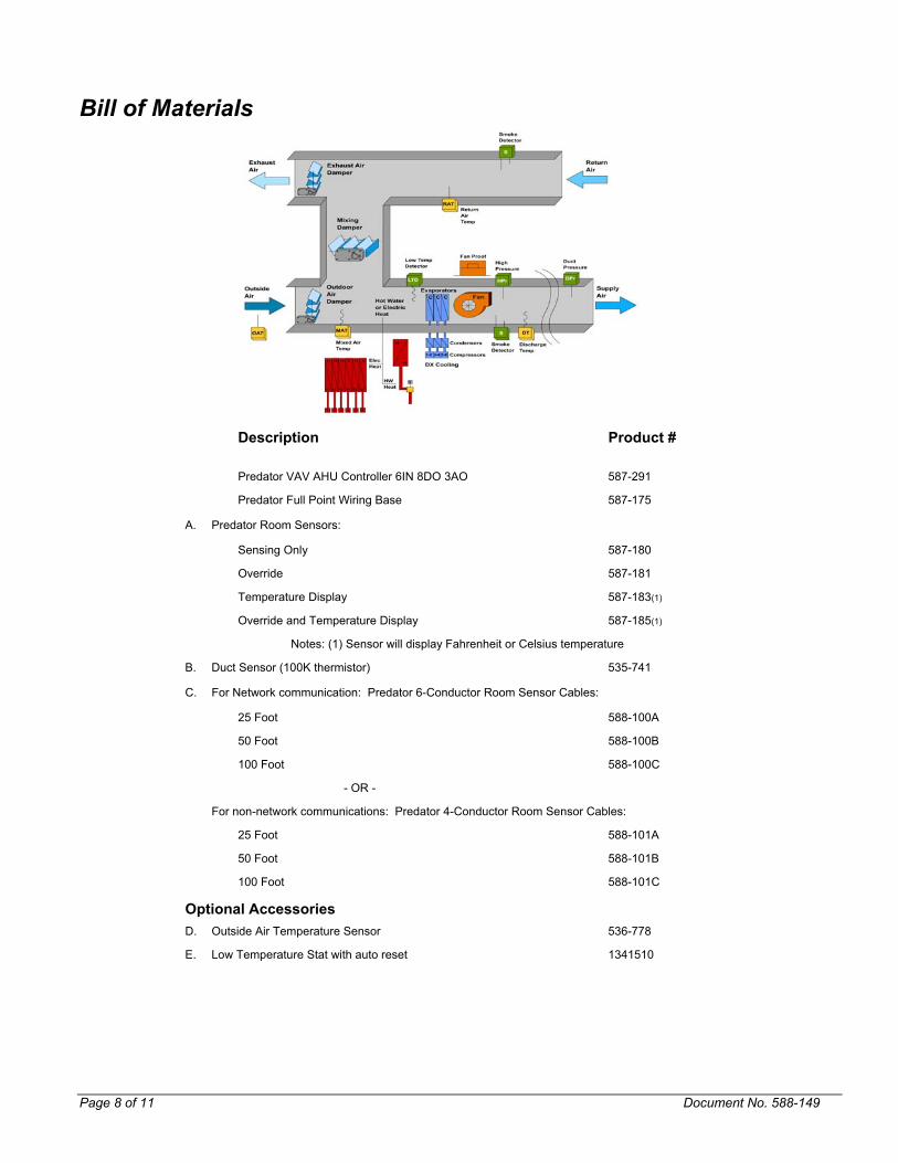
Bill of Materials
Description Product #
Predator VAV AHU Controller 6IN 8DO 3AO 587-291
Predator Full Point Wiring Base 587-175
A. Predator Room Sensors:
Sensing Only 587-180
Override 587-181
Temperature Display 587-183(1)
Override and Temperature Display 587-185(1)
Notes: (1) Sensor will display Fahrenheit or Celsius temperature
B. Duct Sensor (100K thermistor) 535-741
C. For Network communication: Predator 6-Conductor Room Sensor Cables:
25 Foot 588-100A
50 Foot 588-100B
100 Foot 588-100C
- OR -
For non-network communications: Predator 4-Conductor Room Sensor Cables:
25 Foot 588-101A
50 Foot 588-101B
100 Foot 588-101C
Optional Accessories D. Outside Air Temperature Sensor 536-778
E. Low Temperature Stat with auto reset 1341510
Page 8 of 11 Document No. 588-149

Document No. 588-149 Page 9 of 11
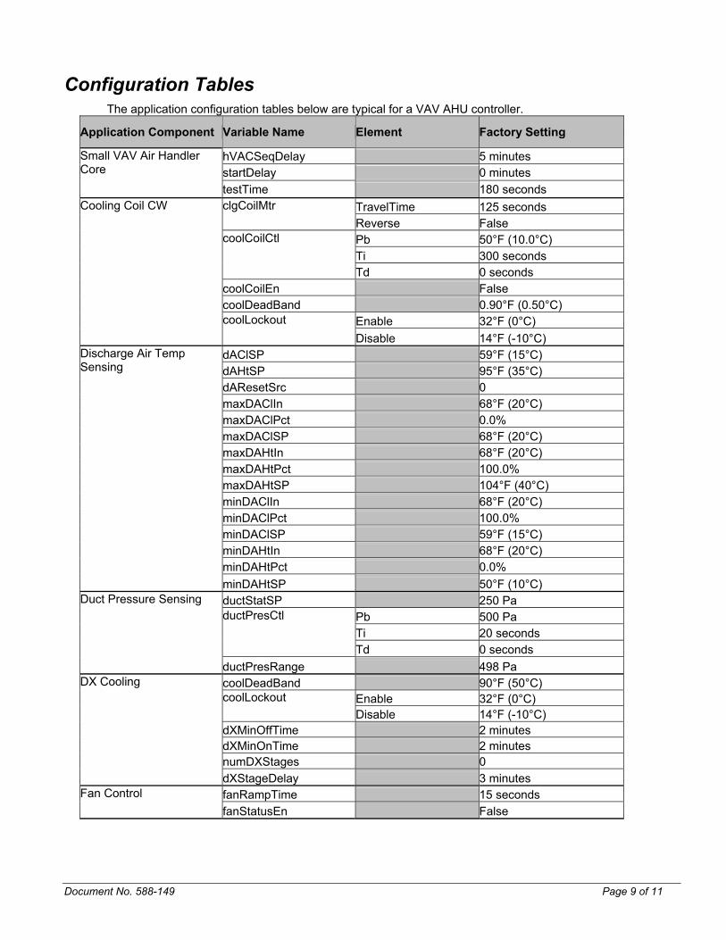
Configuration Tables The application configuration tables below are typical for a VAV AHU controller.
Application Component Variable Name Element Factory Setting
hVACSeqDelay 5 minutes startDelay 0 minutes
Small VAV Air Handler Core
testTime 180 seconds TravelTime 125 seconds clgCoilMtr Reverse False Pb 50°F (10.0°C) Ti 300 seconds
coolCoilCtl
Td 0 seconds coolCoilEn False coolDeadBand 0.90°F (0.50°C)
Enable 32°F (0°C)
Cooling Coil CW
coolLockout Disable 14°F (-10°C)
dAClSP 59°F (15°C) dAHtSP 95°F (35°C) dAResetSrc 0 maxDAClIn 68°F (20°C) maxDAClPct 0.0% maxDAClSP 68°F (20°C) maxDAHtIn 68°F (20°C) maxDAHtPct 100.0% maxDAHtSP 104°F (40°C) minDAClIn 68°F (20°C) minDAClPct 100.0% minDAClSP 59°F (15°C) minDAHtIn 68°F (20°C) minDAHtPct 0.0%
Discharge Air Temp Sensing
minDAHtSP 50°F (10°C) ductStatSP 250 Pa ductPresCtl Pb 500 Pa Ti 20 seconds Td 0 seconds
Duct Pressure Sensing
ductPresRange 498 Pa DX Cooling coolDeadBand 90°F (50°C) Enable 32°F (0°C)
coolLockout Disable 14°F (-10°C)
dXMinOffTime 2 minutes dXMinOnTime 2 minutes numDXStages 0 dXStageDelay 3 minutes Fan Control fanRampTime 15 seconds fanStatusEn False

Application Component Variable Name Element Factory Setting
Modulating Heat Pb 68°F (20°C) Ti 300 seconds
heatCoilCtl
Td 0 seconds heatCoilEn False TravelTime 125.0 seconds
htgCoilMtr Reverse FALSE
heatDeadBand 0.90°F (0.50°C) Enable 68°F (20°C)
heatLockout Disable 71.6°F (22°C)
heatUnit Off econControl Enabled econDBand 1.8°F (1°C)
Source SRC_RETURN_TEMP FixedTemp 68°F (20°C)
econRef
Offset 35.6°F (2°C) Pb 95°F (35°C) Ti 200 seconds
oADmprCntr
Td 0 seconds oAMinPos 0%oAReducedPos 0%oATempAdaptEn Enable vDmdDesign 100%
OA Damper Control with Mixed Air
vDmdReduced 0.0% Occupancy Control bypassTime 60 minutes statSwitchEn False OccupiedClg 73°F (23°C) StandbyClg 77°F (25°C) UnoccupiedClg 82°F (28°C) OccupiedHtg 70°F (21°C) StandbyHtg 66°F (19°C)
setpoints
UnoccupiedHtg 61°F (16°C) unocDeadBand 3.6°F (2°C) Duration 0 minutes OutTemp 50°F (10°C)
warmupTrig
InTemp 62°F (17°C) hiPressLatch Enable Safeties loTempLatch Enable
Staged Heat heatDeadBand 0.90°F (0.50°C) Enable 68°F (20°C)
heatLockout Disable 71.6°F (22°C)
htStageDelay 300 seconds numHStages 0
Page 10 of 11 Document No. 588-149

Document No. 588-149 Page 11 of 11
Control Mode Interaction Table
Device Mode Occupied Unoccupied Safety Off Fan
Only Starting
(Fan Proof) cool heat cool Idle heat low
temp other safety
Fan off mod mod mod mod mod off mod off off OA damper close close close mod min mod close close close close Cool valve off off off mod off mod off off open off Stage heat off off off stage stage stage off stage off off Heat valve off off select mod mod mod select mod open off
Color Key: Red = OFF (not used); Green = Active (fixed in application); Yellow = Selectable (configurable) Notice: Information in this document is based on specifications believed correct at the time of publication. The right is reserved to make changes as design improvements are introduced. Credits: Staefa Control System, Raptor, Predator, and TALON are trademarks of Siemens Building Technologies, Inc. Niagara Framework is a registered trademark of Tridium, Inc. Other products and company names herein may be the trademarks of their respective owners. Siemens Building Technologies, Inc. HVAC Products 1000 Deerfield Parkway Buffalo Grove, Illinois 60089 Phone 847-215-1000 www.staefa.com Copyright 2001 by Siemens Building Technologies, Inc.

Single Fan VAV AHU DX Cooling with Options
Application Data Sheet
Figure 1. Single Fan DX VAV AHU with selectable hot water or electric heat and options
Features • LONMARK compliant with Discharge Air Controller Functional Profile (8610) • Economizer cycle driven by local dry bulb logic or network override • Minimum ventilation setting responds to air quality input for demand controlled ventilation • Multiple options for supply air temperature reset to optimize system performance • Interoperates with LonMark zone controllers to coordinate occupancy and air conditioning
functions • Adaptive control of outdoor air dampers responds quickly and stably in any season • PID control minimizes offset and maintains tighter set point control • Conforms to the LONMARK interoperability guidelines, enabling information sharing with LONMARK
products from other vendors.
Document No. 588-150 March 2003

Sequence of Operation
Occupied Control General The supply fan starts slowly and runs throughout the occupied mode. A PID control loop continually adjusts the fan capacity to maintain the duct static pressure at setpoint as loads vary in the zones. The duct pressure setpoint may be an adjustable constant, or may be varied automatically by another node to minimize energy consumption. Ventilation Control Ventilation (DCV) During occupied mode, the outdoor air damper opens to the design ventilation setting and stays open. When Demand Controlled Ventilation (DCV) is implemented, the ventilation setting may be automatically adjusted from internally in the Predator or by another node to a value appropriate for the demand. The Predator DCV function is adjustable, while the ventilation demand value comes from another node. The supply air temperature setpoint may be adjusted manually or varied according to an adjustable built-in reset function. Discharge Temperature Control
Hot Water Option When free cooling is available, the heating coil valve, outdoor air damper, and stages of DX cooling operate sequence to maintain discharge air temperature setpoint. The outdoor air damper does not close beyond the current ventilation setting. When free cooling is unavailable, the outdoor air damper goes to the current ventilation setting; the heating coil valve modulates and stages of cooling operate in sequence to maintain discharge air temperature setpoint. Staged Heat Option When free cooling is available, the heat stages, outdoors air damper, and stages of cooling operate in sequence to maintain discharge air temperature setpoint. The outdoor air damper does not close beyond the current ventilation setting. When free cooling is unavailable, the outdoor air damper goes to the current ventilation setting; the heat stages and stages of cooling operate in sequence to maintain discharge air temperature setpoint.
Unoccupied Control General During unoccupied periods, the air handler is normally off. The outdoor damper is closed and the DX equipment is off. The optional hot water coil valve may be forced closed, or it may operate to maintain unit temperature above freezing. Optional staged heat stages are turned off. The Predator may run the air handler intermittently to provide heating or cooling in response to demand from the associated unoccupied zone controllers. Unoccupied Cooling Mode The air handler starts in response to a cool or pre-cool command from the network or measured zone temperature above the unoccupied setpoint. The Predator modulates the supply fan capacity to maintain measured duct pressure at the duct static pressure setpoint. If free cooling is not available, the outdoor air damper closes fully. Mechanical cooling may be locked out during unoccupied periods.
Page 2 of 11 Document No. 588-149

Document No. 588-149 Page 3 of 11
Unoccupied Heating Mode The air handler starts in response to a heat or warm-up command from the network or measured zone temperature below the unoccupied setpoint. The Predator modulates the supply fan capacity to maintain measured duct pressure at the duct static pressure setpoint. The hot water coil or staged heat is operated to maintain the supply air temperature at the heating setpoint. The stages of DX cooling are off and the outdoor air damper is closed.
Safety Shutdown Low Temperature If a Low Temperature is detected the OA damper closes and the fan shuts off. The stages of cooling are turned off. The optional hot water coil valve opens fully; optional staged heat is turned off. The system may be configured to re-start automatically after the condition clears, or to remain shut down until a manual reset. Other Safeties Any number of other safety devices, such as smoke detectors or a high duct pressure switch, may be applied to shut the unit down. The Predator turns off the fan, closes the OA dampers, closes the hot water coil valve and turns off the cooling stages. The Predator indicates an alarm condition over the network, and remains shut down until reset manually.
Off In this mode, the heating coil valve and OA damper are closed, and the cooling stages and fan are off.
Temperature Control Sequence Diagrams
100% Open
DamperMinimum
0%
HeatingValve
DXCooling
Air Conditioning Load
Outdoor AirDamper
The Predator sequences heating, cooling and outsideair as needed to meet air contidioning load.
Special Features
System Level Occupancy Control Occupancy for an air handler should be coordinated with occupancy for its respective zones. A site may employ more than one of the following interoperation mechanisms to accomplish system level coordination:
• The Predator Air Handler Controller may drive occupancy of the zones through bound network variables.
• The zone controllers may drive occupancy of the air handler so that it runs to meet their needs.
• Occupancy of the zones and air handler may both be driven in a coordinated way by another LonMark device.
The Predator responds to LonMark occupancy override (nviOccManCmd), allowing a building operator or technician to override the system from any LonMark compatible user interface.
The Predator responds to a LonMark compatible occupancy schedule input (nviOccSchedule). This allows the Predator to utilize the scheduling functions of other devices on the LonTalk Network.
The primary occupancy signal could also come from a time clock, wall switch, or occupancy sensor physically wired to one of the inputs of the Predator. This occupancy signal can then be shared with other controllers via the LonTalk Network.
Duct Pressure Reset To comply with ASHRAE Standard 90.1, Energy Efficiency for Commercial Buildings, the Predator supports automatic duct pressure reset by accepting a variable setpoint. The dynamic setpoint may calculated according to any algorithm in another device, and transmitted over the network.
Supply Temperature Reset The Predator can run an air handler as a classic constant-temperature VAV system, or it can dynamically adjust the supply temperature to adapt to loading conditions. The temperature may be reset using a built-in adjustable reset schedule, or calculated externally with a custom algorithm, and transmitted via the LonWorks network. The built-in reset schedules directly support the most popular approaches: reset based on space temperature, return temperature, outdoor temperature or a selected percentage demand signal from the zone controllers.
Demand Controlled Ventilation The Predator can control ventilation by the industry standard approach, using an adjustable minimum OA damper opening or by a demand-controlled strategy that adjusts the OA intake according to IAQ measurements in the occupied spaces. The DCV lets an HVAC designer build the system for the maximum anticipated ventilation requirements, but operate the system more economical ventilation rates when the actual demand is lower.
Night Heating and Cooling
Page 4 of 11 Document No. 588-149
The Predator supports several heating and cooling options for unoccupied periods. Using zone temperature data that either comes from the directly connected zone sensor or delivered over the network, the controller can cycle the air handler to meet heating and cooling needs of the zones. This function requires no intervention from a supervisory node. If some other start/stop criteria is required, another node may implement that logic and command the air handler on and off during the unoccupied period.

Document No. 588-149 Page 5 of 11
In cold climates, to prevent mechanical equipment freeze up, there is a need to keep the air handler warm even when the fan is off. The Predator can cycle or modulate an optional hot water valve to keep the mixed air temperature (or discharge temperature) within a desired range while the fan is off. The Predator can initiate a warm-up sequence for the zones. When the zone temperature and the outdoor temperature are both below adjustable limits and occupancy is due to start soon, the Predator switches to warm-up mode. It issues a network command for the zone controllers to put them in warm-up mode. The only inputs required are the zone temperature and the LonMark compatible schedule variable.
Adaptive Control of Outdoor Air Damper Past history has proven that tuning for economizer control loops poses problems. For example, when it is particularly cold outside, a small damper movement can cause a big change in the mixed air temperature. The control loop is likely to overshoot or even oscillate which can cause big problems in the air-handling unit. To prevent oscillation, it is necessary to tune the loop specifically for the cold-weather case. Then when warmer weather arrives, the cold-weather tuning leads to sloppy control and an ineffective air conditioning system. The Predator addresses this dilemma directly by automatically adjusting the economizer control loop tuning to suit the outdoor temperature. Without any attention or maintenance, the loop is always fast, stable and accurate, making the economizer truly economical.

Hardware Map – VAV AHU Termination Set Parameter Set in Element Name I/O Type Factory I/O Setting
StatTemp statTemp SPACE_TEMP StatSetpt statSetpt
TEMP IN_UNUSED
StatOvrd statOvrd DI STAT_SWITCH_DI In1 in1 DISCH_TEMP In2 in2
DI, TEMP RETRN_TEMP
In3 in3 DUCT_PRESS In4 in4 FAN_STATUS_DI In5 in5 LOW_TEMP_DI In6
inputs
in6
DI, PCT, TEMP
HI_PRESS_DI OutA1 outA1 SUP_FAN_CAP_AO OutA2 outA2 OA_DMPR_AO OutA3 outA3
AO
HEAT_COIL_AO OutD1 outD1 SUP_FAN_DO OutD2 outD2 OA_DAMPER_2POS_DO OutD3 outD3 DX_STAGE1_DO OutD4 outD4 DX_STAGE2_DO OutD5 outD5 DX_STAGE3_DO OutD6 outD6 DX_STAGE4_DO OutD7 outD7 HEAT_STAGE1_DO OutD8
outputs
outD8
DO, FLT_MTR
HEAT_STAGE2_DO
Table 1. Hardware Map
Page 6 of 11 Document No. 588-149

Document No. 588-149 Page 7 of 11
Wiring Diagram
Note: Route wiring from either the bottom opening when using a J-box or from the base sides as shown in the picture when flat or din rail mounting. The image above is for illustrative purposes only
Wiring Recommendations:
IN and AO: 20 to 22 AWG DO: 18 to 22 AWG Power: 16 to 18 AWG
LON Network: 22 AWG Level 4
Transformer Requirements:
Type: Class 2, 24 VAC, 50/60Hz
Figure 3. Predator Wiring Diagrams
Bill of Materials
Description Product #
Predator VAV AHU Controller 6IN 8DO 3AO 587-291
Predator Full Point Wiring Base 587-175
A. Predator Room Sensors:
Sensing Only 587-180
Override 587-181
Temperature Display 587-183(1)
Override and Temperature Display 587-185(1)
Notes: (1) Sensor will display Fahrenheit or Celsius temperature
B. Duct Sensor (100K thermistor) 535-741
C. For Network communication: Predator 6-Conductor Room Sensor Cables:
25 Foot 588-100A
50 Foot 588-100B
100 Foot 588-100C
- OR -
For non-network communications: Predator 4-Conductor Room Sensor Cables:
25 Foot 588-101A
50 Foot 588-101B
100 Foot 588-101C
Optional Accessories D. Outside Air Temperature Sensor 536-778
E. Low Temperature Stat with auto reset 1341510
Page 8 of 11 Document No. 588-149
Document No. 588-149 Page 9 of 11
Configuration Tables The application configuration tables below are typical for a VAV AHU controller.
Application Component Variable Name Element Factory Setting
hVACSeqDelay 5 minutes startDelay 0 minutes
Small VAV Air Handler Core
testTime 180 seconds TravelTime 125 seconds clgCoilMtr Reverse False Pb 50°F (10.0°C) Ti 300 seconds
coolCoilCtl
Td 0 seconds coolCoilEn False coolDeadBand 0.90°F (0.50°C)
Enable 32°F (0°C)
Cooling Coil CW
coolLockout Disable 14°F (-10°C)
dAClSP 59°F (15°C) dAHtSP 95°F (35°C) dAResetSrc 0 maxDAClIn 68°F (20°C) maxDAClPct 0.0% maxDAClSP 68°F (20°C) maxDAHtIn 68°F (20°C) maxDAHtPct 100.0% maxDAHtSP 104°F (40°C) minDAClIn 68°F (20°C) minDAClPct 100.0% minDAClSP 59°F (15°C) minDAHtIn 68°F (20°C) minDAHtPct 0.0%
Discharge Air Temp Sensing
minDAHtSP 50°F (10°C) ductStatSP 250 Pa ductPresCtl Pb 500 Pa Ti 20 seconds Td 0 seconds
Duct Pressure Sensing
ductPresRange 498 Pa DX Cooling coolDeadBand 90°F (50°C) Enable 32°F (0°C)
coolLockout Disable 14°F (-10°C)
dXMinOffTime 2 minutes dXMinOnTime 2 minutes numDXStages 0 dXStageDelay 3 minutes Fan Control fanRampTime 15 seconds fanStatusEn False

Application Component Variable Name Element Factory Setting
Modulating Heat Pb 68°F (20°C) Ti 300 seconds
heatCoilCtl
Td 0 seconds heatCoilEn False TravelTime 125.0 seconds
htgCoilMtr Reverse FALSE
heatDeadBand 0.90°F (0.50°C) Enable 68°F (20°C)
heatLockout Disable 71.6°F (22°C)
heatUnit Off econControl Enabled econDBand 1.8°F (1°C)
Source SRC_RETURN_TEMP FixedTemp 68°F (20°C)
econRef
Offset 35.6°F (2°C) Pb 95°F (35°C) Ti 200 seconds
oADmprCntr
Td 0 seconds oAMinPos 0%oAReducedPos 0%oATempAdaptEn Enable vDmdDesign 100%
OA Damper Control with Mixed Air
vDmdReduced 0.0% Occupancy Control bypassTime 60 minutes statSwitchEn False OccupiedClg 73°F (23°C) StandbyClg 77°F (25°C) UnoccupiedClg 82°F (28°C) OccupiedHtg 70°F (21°C) StandbyHtg 66°F (19°C)
setpoints
UnoccupiedHtg 61°F (16°C) unocDeadBand 3.6°F (2°C) Duration 0 minutes OutTemp 50°F (10°C)
warmupTrig
InTemp 62°F (17°C) hiPressLatch Enable Safeties loTempLatch Enable
Staged Heat heatDeadBand 0.90°F (0.50°C) Enable 68°F (20°C)
heatLockout Disable 71.6°F (22°C)
htStageDelay 300 seconds numHStages 0
Page 10 of 11 Document No. 588-149

Document No. 588-149 Page 11 of 11
Control Mode Interaction Table Device Mode
Occupied Unoccupied Safety Off Fan
Only Starting
(Fan Proof) cool heat cool Idle heat low
temp other safety
Fan off mod mod mod mod mod off mod off off OA damper close close close mod min mod close close close close DX off off off stage off mod off off off off Stage heat off off off stage stage stage off stage off off Heat valve off off select mod mod mod select mod open off
Color Key: Red = OFF (not used); Green = Active (fixed in application); Yellow = Selectable (configurable) Notice: Information in this document is based on specifications believed correct at the time of publication. The right is reserved to make changes as design improvements are introduced. Credits: Staefa Control System, Raptor, Predator, and TALON are trademarks of Siemens Building Technologies, Inc. Niagara Framework is a registered trademark of Tridium, Inc. Other products and company names herein may be the trademarks of their respective owners. Siemens Building Technologies, Inc. HVAC Products 1000 Deerfield Parkway Buffalo Grove, Illinois 60089 Phone 847-215-1000 www.staefa.com Copyright 2001 by Siemens Building Technologies, Inc.