sir c.r.reddy college of engineering eluru-534007 · sir c.r.reddy college of engineering...
TRANSCRIPT

SIR C.R.REDDY COLLEGE OF ENGINEERING
ELURU-534007
STRENGTH OF MATERIALS LABORATORY
MANUAL
II/IV B.TECH (Mechanical): I SEMESTER
DEPARTMENT OF MECHANICAL ENGINEERING
SIR C.R.REDDY COLLEGE OF ENGINEERING
DEPARTMENT OF MECHANICAL ENGINEERING 1
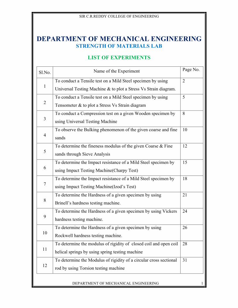
DEPARTMENT OF MECHANICAL ENGINEERING STRENGTH OF MATERIALS LAB
LIST OF EXPERIMENTS
Sl.No. Name of the Experiment Page No.
1 To conduct a Tensile test on a Mild Steel specimen by using
Universal Testing Machine & to plot a Stress Vs Strain diagram.
2
2 To conduct a Tensile test on a Mild Steel specimen by using
Tensometer & to plot a Stress Vs Strain diagram
5
3 To conduct a Compression test on a given Wooden specimen by
using Universal Testing Machine
8
4 To observe the Bulking phenomenon of the given coarse and fine
sands
10
5 To determine the fineness modulus of the given Coarse & Fine
sands through Sieve Analysis
12
6 To determine the Impact resistance of a Mild Steel specimen by
using Impact Testing Machine(Charpy Test)
15
7 To determine the Impact resistance of a Mild Steel specimen by
using Impact Testing Machine(Izod’s Test)
18
8 To determine the Hardness of a given specimen by using
Brinell’s hardness testing machine.
21
9 To determine the Hardness of a given specimen by using Vickers
hardness testing machine.
24
10 To determine the Hardness of a given specimen by using
Rockwell hardness testing machine.
26
11 To determine the modulus of rigidity of closed coil and open coil
helical springs by using spring testing machine
28
12 To determine the Modulus of rigidity of a circular cross sectional
rod by using Torsion testing machine
31

SIR C.R.REDDY COLLEGE OF ENGINEERING
DEPARTMENT OF MECHANICAL ENGINEERING 2
1. TENSILE TEST ON UTM AIM: To conduct a tensile test on a mild steel specimen by using Universal Testing Machine and to plot a stress – strain diagram. APPARATUS: Universal testing machine, vernier callipers, scale, REQUIRED MATERIAL: Mild Steel Rod of given dimension THEORY: This test consists in straining a test piece by tensile stress, generally to
fracture with a view to determine one or more of the mechanical properties. Usually this
test is conducted at room temperature and the tensile load is applied slowly. The load on
the specimen is applied either mechanically or hydraulically depending on the type of
testing machine.
In this test, the specimen is gripped between fixed and movable heads of universal
testing machine. The test load is increased gradually. An elastically deformed solid will
return to its original form as soon as load is removed. However if the load is too large, the
material can be deformed permanently in initial part of the tension curve, which is
recoverable immediately after unloading is termed as elastic and the rest of the curve
which represent the manner is which solid under goes plastic deformation is termed as
plastic. The stress below which the deformation is essentially entire elastic is known as
yield strength of the material. During plastic deformation at larger extensions strain
hardening cannot compensate for the decrease in section and thus the load passes through
a maximum then begins to decrease. As this stage is “ultimate strength” which is defined
as the ratio of the load on the specimen to original cross sectional area reaches a
maximum value. Further loading will externally cause ‘neck’ formation and rupture.
During this test either round or flat specimen may be used. The round specimen may have
smooth shoulders or threaded ends for gripping.
PROCEDURE:
1. Measure the original length and dia of the specimen. The length may either be length of gauge section which is measured in the specimen with a preset punch or the total length of the specimen.
2. Insert the specimen into grips of the test machine.

SIR C.R.REDDY COLLEGE OF ENGINEERING
DEPARTMENT OF MECHANICAL ENGINEERING 3
3. Begin the load application and record the load Vs elongation data. 4. Take the readings more frequently as yield point is approached.
5. Measure elongation values with the help of divider & rulers. 6. Continue the test till fracture occurs.
7. By joining the two broken pieces of the specimen together, measure the final length and diameter of the neck portion.
% Elongation (By gauge) = ________________ % Reduction in area (By gauge) = ______________________
OBSERVATIONS: Initial length of the specimen (li ) = mm Initial diameter of the specimen (di) = mm
S.No Load (P) Newtons
Elongation δ l mm
Tensile stress
sAPt =σ
Strain
illδ
Ultimate tensile load = P kN Final length of the specimen lf = mm
Dia at break point of specimen df = mm
( )100
lll
Elongation%i
if ×−
=
100d4
d4
d4reaductioninaRe%
2i
2f
2i
×π
⎟⎠
⎞⎜⎝
⎛ π−
π
=
Ultimate tensile stress = 100d4
Put2i
π=σ N/mm2
Graph:
Draw a graph between the stress and the strain PRECAUTIONS:
1. The specimen should be firmly fixed in the grips. 2. The pointer on the load scale must be adjusted to zero before the text begins.

SIR C.R.REDDY COLLEGE OF ENGINEERING
DEPARTMENT OF MECHANICAL ENGINEERING 4
3. The load and extension must be recorded simultaneously. 4. The movement of the pointer on the load scale must be watched continuously to
get the upper and the lower yield points.
VIVA QUESTIONS
1. What is Elasticity?
2. What is Plasticity?
3. What do you mean by ductility?
4. What do you mean by malleability?
5. What do you understand by toughness or tenacity?
6. Define Hook’s law?
7. What is the limit of proportionality?
8. What do you mean by Elastic limit?
9. Define Young’s modulus?
10. What do you mean by permanent set?
11. Draw the stress strain diagram for a mild steel material?
12. Draw the stress strain diagram for a brittle material?
13. Give few examples for brittle materials?
14. Give few examples for ductile materials?
15. What do you mean by percentage elongation?
16. What do you understand by strain hardening?
17. Indicate the plastic zone in stress strain diagram for mild steel material?
18. What is the difference between ductile and brittle material?
19. What do you mean by percentage reduction in area?
20. Define factor of safety?

SIR C.R.REDDY COLLEGE OF ENGINEERING
DEPARTMENT OF MECHANICAL ENGINEERING 5
2. TENSOMETER
AIM: To conduct a tensile test on a mild steel specimen by using tensometer & to plot the stress – strain diagram. APPARATUS: 1) Tensometer(microtech) 2) 12th Numbered chucks 3) Percentage elongation gauge 4) Percentage area reduction gauge THEORY: The tensile test is one of the mechanical test which is the most applied. Usually this test is conducted at room temperature and the tensile load is applied slowly. The load on the specimen is mechanically or hydraulically applied depending on the type of testing machine. In the test, the specimen is gripped between fixed and movable heads of universal testing machine. The test load is increased gradually. An elastically deformed solid will return to its original form as soon as load is removed. However if the load is too large, the material can be deformed permanently. The initial part of the tension curve, which is recoverable immediately after unloading is termed as elastic and the rest of the curve which represent the manner in which solid undergoes plastic deformation is termed plastic. The stress below which the deformation is essentially entirely elastic is known as the yield strength of the material. During plastic deformation at larger extensions strain hardening cannot compensate for the decrease in section and thus the load passes through a maximum & then begins to decrease. As this stage is the “ultimate strength” which is defined as the ratio of the load on the specimen to original cross sectional area reaches a maximum value. Further loading will eventually cause, ‘neck’ formation and rupture. During this test either round or flat specimen may be used. The round specimen may have smooth shoulders or threaded ends. PROCEDURE:
1. Measure the original length and diameter of the specimen. The length may either be length of gauge section which is marked in the specimen with a preset punch or the total length of the specimen.
2. Insert the specimen into grips of the test machine & attach strain-measuring device to it.
3. Begin the load application and record load verses elongation data.
4. Take readings more frequently as yield point is approached 5. Measure elongation values with the help of divider & rulers
6. Continue the test till the fracture occurs 7. By joining the two broken pieces of the specimen together, measure the final length
and diameter of the specimen % elongation (By gauge) = _____
% reduction in area (By gauge) = _____

SIR C.R.REDDY COLLEGE OF ENGINEERING
DEPARTMENT OF MECHANICAL ENGINEERING 6
OBSERVATIONS: Before conducting the test:
Total length of the specimen = l = _________mm Step length of the specimen = l1 = ___________ mm
Effective length of the specimen = li = l – 2l1 Diameter of the specimen = di = ____ mm
Area of the cross section = 2ii d
4A ×
Π=
After conducting the test: Total length of the specimen = lo = ____ mm Elongated length = lf = lo-2l1 Diameter = df = ____ mm
Area of the cross section = 2ff d
4A ×
Π=
1) Percentage elongation
i) From calculation = ((lf – li)/ li) 100 ii) By gauge = ____ 2) Percentage reduction in area
i) From calculation = 100AAA
i
fi ×−
ii) By gauge = ____
S.No Load p
(kgf)
Elongation ‘x’
(mm)
δl = x/16
(mm)
Stress σ = p/a kgf/mm2
Strain ∈ δl/l
PRECAUTIONS: If the strain measuring device is an extensometer it should be removed before necking begins. RESULT: Yield point stress = ____ kgf/mm2
Breaking stress = _______ kgf/mm2

SIR C.R.REDDY COLLEGE OF ENGINEERING
DEPARTMENT OF MECHANICAL ENGINEERING 7
VIVA QUESTIONS
1) What is the aim of the experiment?
2) What are the apparatus required to conduct this experiment?
3) What do you mean by percentage reduction in area?
4) How is the load applied on the specimen depending on the type of testing?
5) What type of specimen may be used during the test?
6) How do you find the final length of the specimen?
7) How do you measure the elongation values?

SIR C.R.REDDY COLLEGE OF ENGINEERING
DEPARTMENT OF MECHANICAL ENGINEERING 8
3. COMPRESSION TEST ON UTM AIM: To conduct a compression test on a given wooden specimen by using Universal testing machine. APPARATUS: Universal Testing Machine, Vernier Callipers, Scale MATERIAL REQUIRED: Wooden piece of the given size PROCEDURE:
1. Measure the length, sides of the specimen and see that the sample aspect ratio, (length/side) should be approximately 1.5
2. Place the sample on a cylindrical block which is kept on the bed of the machine and adjust the axis of the sample so that it coincides with the axis of the lead screw of the machine.
3. The lead screw of the machine is slowly and gradually lowered and when the gap between sample and compression plate is removed, the load starts acting on the sample.
4. Rotate the hand wheel slowly and gradually and note down the load continuously. 5. At a max load, the sample failed and the resistance of the sample is decreased,
therefore load recorded is also less. 6. Repeat the above by loading the other wooden piece perpendicular to the axis of the
piece. OBSERVATIONS:
Length of the specimen (l) = mm
Width of the specimen (b) = mm
Thickness of the specimen (t) = mm
Area of the specimen perpendicular to the grains – b x t - mm2
Area of the specimen parallel to the grains = l x b = mm2
Ultimate Compressive load in parallel to grains = Pult (Parallel) = N
Ultimate Compressive load in perpendicular to grains = Pult (Perpendicular) = N
Ultimate compressive stress (Parallel to grains) = 2ult mm/Nbxt
)Parallel(P
Ultimate compressive stress (Perpendicular to grains) = 2ult mm/N
lxb)larPerpendicu(P

SIR C.R.REDDY COLLEGE OF ENGINEERING
DEPARTMENT OF MECHANICAL ENGINEERING 9
PRECAUTIONS:
1. The axis of the sample should be adjusted to the axis of lead screw.
2. The load should be applied slowly and gradually 3. Eccentric loading should be avoided.
4. The sample should be placed on the bed with its grains pointing in the direction of loading.
RESULT:
1. The compressive strength of the given wooden piece perpendicular to the grains is __________________________ N/mm2.
2. The compressive strength of the given wooden piece parallel to the grains is ___________________________ N/mm2.
\

SIR C.R.REDDY COLLEGE OF ENGINEERING
DEPARTMENT OF MECHANICAL ENGINEERING 10
4. BULKING OF SAND
AIM: To observe the bulking phenomenon of the given Coarse and Fine sands.
APPARATUS: Measuring bar, Mixing Jar, Pipette
MATERIAL: Dry sand (Coarse sand and fine sand) and water
THEORY: The increase in volume of sand due to presence of surface moisture up to some extent is called bulking of sand. When the sand was moistured every particle of it gets covered with a thin film of surface moisture which tend to keep the particle away from one another thus causing bulking of sand. The bulking of fine sand is greater than that of coarse sand. If the percentage of moisture content goes on increasing the increase in sand bulking decreases. PROCEDURE: 1. 200 CC volume of open dried sand is taken into a measuring jar.
2. An amount of water equal to 2% by volume of sand is added to this dry sand and the
total volume of sand and water is taken as Vt
3. Sand and water is thoroughly mixed in a mixing pan and the volume of wet sand is
measured i.e. Vo
4. The percentage volume of bulking sand is calculated by the formula [(Vo – Vt) / Vt] x
100
5. The process of adding water at an interval of 2% is continued till the error becomes
zero
6. A graph is drawn by taking moisture content on x-axis and % error on y– axis
showing the bulking phenomenon of given sample sand.
OBSERVATIONS: Coarse sand:
S.No Volume of sand
Volume of
water added
Theoretical volume
Vt
Observed volume
Vo
Error Vo-Vt
% error (Vo – Vt)/Vt x
100

SIR C.R.REDDY COLLEGE OF ENGINEERING
DEPARTMENT OF MECHANICAL ENGINEERING 11
Fine sand:
S.No Volume of sand
Volume of
water added
Theoretical volume
Vt
Observed volume
Vo
Error Vo-Vt
% error (Vo – Vt)/Vt x
100
PRECAUTIONS: 1. Mixing of water should be done thoroughly
2. The volume of sand/water and observed volume should be measured accurately.
RESULT: 1. Maximum bulking of coarse sand occurred at ____% of moisture content is ___
2. Maximum bulking of fine sand occurred at ____ % of moisture content is ____
3. The phenomena of bulking is observed for coarse sand & fine sand.
VIVA QUESTIONS
1) What is the aim of the experiment ?
2) What do you mean by bulking of sand ?
3) What is the equipment and materials required to conduct this experiment ?
4) How many types of sands are used in this experiment ?
5) For what types sand , the bulking of sand is more ?
6) If the percentage of moisture content goes on the decreasing what will happen to
the sand bulking ?
7) The process of adding water at interval of two percent is continued till -----------
8) A graph is drawn by taking moisture content on -----axis and % error on -------
axis
9) What precautionary measures are to be taken for this experiment?
10) What is the porosity?
11) What is collapsibility and flowability?
12) What is grain fine ness number and what does it exactly indicate ?
13) What is the general range of moisture content in the moulding sand ?

SIR C.R.REDDY COLLEGE OF ENGINEERING
DEPARTMENT OF MECHANICAL ENGINEERING 12
5. SIEVE ANALYSIS AIM: To determine the fineness modulus of the given coarse and fine sands through sieve analysis. APPARATUS AND MATERIAL REQUIRED: Given samples of fine and coarse sand aggregates, set of sieves, weighing machine and mechanical sieve shaking machine. THEORY: The index number expressing the relative sizes of both coarse and fine sand aggregate is called fineness modulus. The index number gives an idea about the fineness of coarse aggregate or the mean sizes of particles in the given aggregate. Its volume may be defined by dividing the sum of cumulative percentage in the sieve analysis retained on the each of the ten Indian standard sieves by 200. Total cumulative percentage of weight retained
Fineness modulus = ---------------------------------------------------------------------------------- 100 After finding fineness modulus of coarse and fine sand aggregates separately the percentage of fine to coarse aggregate can be found out from the following relation according to the recommended value of fineness modulus F at the desired mix of the two aggregates.
100FFFF
X1
2 ×−
−=
X = Percentage of fine aggregate to be mixed with coarse aggregate.
F = Recommended value of fineness modulus of the desired mix of fine and coarse aggregate F1 = Fineness modulus of fine aggregate F2 = Fineness modulus of coarse aggregate
PROCEDURE: 1. A specified quality of the samples of the coarse and fine aggregates is taken
depending upon the maximum size of the particles. 2. All the sieves are placed one above the other in an order, such that the finest sieve
remains at the bottom. 3. The specified aggregate of required quantity to be tested is placed in the top most
sieve and the set of sieves is shaken for a period of 20 minutes approximately by switching on the mechanical sieve shaking machine. Then the weight of the residue remained in each sieve is measured using the weighing machine.

SIR C.R.REDDY COLLEGE OF ENGINEERING
DEPARTMENT OF MECHANICAL ENGINEERING 13
OBSERVATIONS: COARSE SAND: Weight of the aggregate (W) = ____ kg
S.No Sieve Number
(mm)
Weight of the material retained
(w) (gms)
% wt of material retained
(w/W)100
Cumulative % wt. Of material retained
c
Fineness modulus of coarse aggregate 100cF2
∑=
FINE SAND: Weight of the aggregate (W) = _____ kg
S.No Sieve Number
mm
Weight of the material retained
(w) gms
% wt of material retained
(w/W)100
Cumulative % wt. Of material retained
c
Fineness modulus of fine aggregate 100cF1
∑= F1
100FFFF
X1
2 ×−
−=
PRECAUTIONS: 1. Splitting of aggregate should be prevented while using 2. Aggregate should be sieved for a period of 20 minutes approximately. 3. Necessary care should be taken by tightening the sieves from falling while the
mechanical sieve shaking machine is vibrating the sieves. 4. The quantity of aggregate retained in each sieve should be weighed accurately
without any error

SIR C.R.REDDY COLLEGE OF ENGINEERING
DEPARTMENT OF MECHANICAL ENGINEERING 14
RESULT 1. Fineness modulus of fine aggregate is _____ 2. Fineness modulus of coarse aggregate is _____ 3. Percentage of the aggregate to be mixed with coarse aggregate is _______ for the
fineness modulus of ______
VIVA QUESTIONS
1) What is the basic aim of the experiment?
2) How the sieves are arranged?
3) What do you mean by sieve number?
4) What do you understand by fineness modulus?
5) Give the expression for percentage of fine aggregate to be mixed with coarse
aggregate?
6) What are the precautionary steps to be taken?
7) What is the composition of moulding sand?
8) What are the properties of moulding sand?
9) List out the types of sands /
10) What is meant by permeability?
11) What is the effect of permeability on sand grains?
12) What do you mean by refractoriness?what happens when it is poor ?
13) Differentiate cohesiveness of sand?

SIR C.R.REDDY COLLEGE OF ENGINEERING
DEPARTMENT OF MECHANICAL ENGINEERING 15
6. CHARPY IMPACT TEST AIM: To determine the impact resistance of a mild steel specimen by using impact testing machine. (charpy test). MATERIAL: Mild steel specimen of dimensions 55 x 10 x 10 mm APPARATUS: Vernier callipers, charpy specimen, scale THEORY: An impact test indicates the toughness of a material & its capacity to resist shock loads. The fault in heat treatment process can be determined by this test. The principle employed in impact testing procedure is that a material absorbs a certain amount of energy there by it breaks. The quantity of energy thus obtained is characteristic of the physical nature of the materials. If it is brittle it breaks more readily and absorbs a lesser quantity of energy and if it is ductile, it needs more energy to fracture. The method of testing is very simple. A swinging hammer is made to strike the
specimen held firmly in a vice. The hammer breaks the specimen on account of its
potential energy. The height of rise of the hammer on the other side indicates the residual
energy of the hammer. The energy actually absorbed by the specimen in order to fracture
is given by the difference between initial and final energies of the pendulum.
In charpy impact test the specimen is placed on the machine as a simple beam.
The opposite face of the notch is fixed to receive the hammer blow. The hammer head
with its pointed arc of 8 mm radius strikes the specimen just in the vertical axis of the
notch.
PROCEDURE: 1. Measure the dimensions of the specimen 2. Raise the pendulum & keep it in position 3. Adjust the pointer on the absorbed energy scale to coincide with initial reading

SIR C.R.REDDY COLLEGE OF ENGINEERING
DEPARTMENT OF MECHANICAL ENGINEERING 16
4. Place the specimen in simply supported beam position on the supports such that notch is opposite to the striking surface.
5. Release the pendulum by pulling the spring. The striking edge strikes against the
specimen and ruptures it. The specimen absorbs a part of the energy due to the fall of pendulum
6. The reading on the scale is recorded and impact resistance of specimen is found out
using the formula.
Impact resistance = Energy absorbed by the specimen / Area of the cross section PRECAUTIONS: 1. The pendulum should be handled very carefully. 2. The specimen must be tightly fixed. 3. The specimen must be placed carefully on a simply supported beam so that the
opposite face of the notch receives the hammer blow. OBSERVATIONS: Least count of the Vernier = 0.02 mm
S.No M.S.R
mm
V.C
mm
V.C x L.C
mm
Total reading M.S.R + (V.C x L.C)
mm
Average width of the specimen = _________ mm
S.No M.S.R
mm
V.C
mm
V.C x L.C
mm
Total reading M.S.R + (V.C x L.C)
mm
Average depth of the specimen = ________ mm

SIR C.R.REDDY COLLEGE OF ENGINEERING
DEPARTMENT OF MECHANICAL ENGINEERING 17
S.No Material Area
(mm2)
Energy absorbed by the specimen
(Joules)
Impact strength
(Joules / m2)
RESULT:
The impact resistance of the given specimen was found to be _______________ Joules /
m2
VIVA QUESTIONS
1. What is the principle involved in charpy impact test? 2. What is the difference between charpy impact test and izoid impact test? 3. What precautions could be taken in charpy impact test? 4. What type of material is used as an impact test specimen?

SIR C.R.REDDY COLLEGE OF ENGINEERING
DEPARTMENT OF MECHANICAL ENGINEERING 18
7. IZOID IMPACT TEST
AIM: To determine the impact resistance of a mild steel specimen by using impact testing machine (Izoid test). APPARATUS: Impact testing machine, Vernier callipers and scale. MATERIAL: Mild steel specimen of size 75mm x 10mm x 10mm. THEORY: The behavior of materials under dynamic loading may sometimes differ remarkably from their behavior under static or gradually increasing loads. In practice the loads on machine members such as chains, hooks, springs, buffers are more or less suddenly applied and usually fail by brittle fracture. Hence there is a need for studying the effects produced by dynamic loading. An impact test indicates the toughness of a material and its capacity to resist shock loads. The fault in heat treatment process can be detected by this test. Non-homogenity of materials can also be found out. In doing impact test, load may be applied in flexure torsion, compression or tension. Flexural loading is the most common one. A swinging pendulum for flexure test may give the impact blow. In such tests a large amount of the energy absorbed is taken up in a region immediately adjacent to the notch and a brittle type of fracture is often induced. This property of a material relating to the convection and air resistance on the pendulum may be made by repeating the experiment without placing a specimen on the anvil. The energy test in friction Kf may be computed. The actual energy absorbed is given by the equation Ka = K – Kf. The measure of the toughness or the resistance to shock loads is called impact strength and is usually expressed as the energy required to fracture the specimen of unit cross sectional area.
Impact strength = o
a
AK Joules/m2
Where Ka = Energy required to fracture the specimen in Joules Ao = Cross sectional area of the specimen at notch in m2.
PROCEDURE: 1. Measure the dimensions of the specimen accurately 2. Rise the pendulum and keep it in position such that the pendulum makes an angle of
850 with the vertical. 3. Fix the specimen in a specimen holder vertically so that the hammer strikes the notch
face. 4. Adjust the pointer to coincide with the initial reading. 5. Release the pendulum by pulling the IZOID release lever

SIR C.R.REDDY COLLEGE OF ENGINEERING
DEPARTMENT OF MECHANICAL ENGINEERING 19
6. The striking edge strikes against the specimen and raptures it. 7. Specimen absorbs a part of the energy due to fall of pendulum and the reading on
IZOID scale is noted.
8. Impact strength at notch is calculated as per the formula AKI a=
I – impact strength in Joules/m2 Ka – Energy absorbed during rupture in Joules A – Area of cross section of the specimen below the notch in m2
OBSERVATIONS: Least count of vernier callipers= _______ mm Breadth of the specimen:
S.No Main Scale Reading MSR
(mm)
Vernier coincidence VC
VC x LC
(mm)
Total reading MSR + VC x LC
(mm)
1 2 3
Average breadth of the specimen is _____mm Width of the specimen:
S.No Main Scale Reading MSR
(mm)
Vernier coincidence
VC
VC x LC
(mm)
Total reading MSR + VC x LC
(mm) 1 2 3
Average width of the specimen is _________ mm Area of the specimen below the notch A A = Width x Breadth
Material of the specimen
Cross sectional area
A (m2)
Energy absorbed
Ka (Joules)
Impact strength I = Ka/A
(Joules/m2)

SIR C.R.REDDY COLLEGE OF ENGINEERING
DEPARTMENT OF MECHANICAL ENGINEERING 20
PRECAUTIONS: 1. The specimen should not be kept in the fixture after raising/ releasing the pendulum. 2. Vernier callipers reading should be taken without parallax error. 3. The brake should be applied when the pendulum is in forward direction only. 4. A distance must be observed from the machine while releasing the pendulum in a
safety point of view RESULT: Impact strength of the given mild steel piece is: ______________ Joules/m2
VIVA QUESTIONS
1. What is the maximum impact energy in case of Izoid test?
2. What is the angle of draft in case of Izoid impact test?
3. What is the minimum scale graduation in both the impact tests?
4. What are the units for Impact strength?
5. What do you mean by impact strength?
6. What is the least count of vernier callipers?
7. What is the equipment required to conduct Izoid impact test?
8. What Izoid precautionary measures should be taken for Izoid test?
9. With what formula one can calculate the impact strength at notch?
10. How do you detect the fault in the heat treatment process?
11. What is the Angle of draft in case of charpy impact test?
12. What is the striking velocity of the hammer in case of charpy impact test?
SIR C.R.REDDY COLLEGE OF ENGINEERING
DEPARTMENT OF MECHANICAL ENGINEERING 21
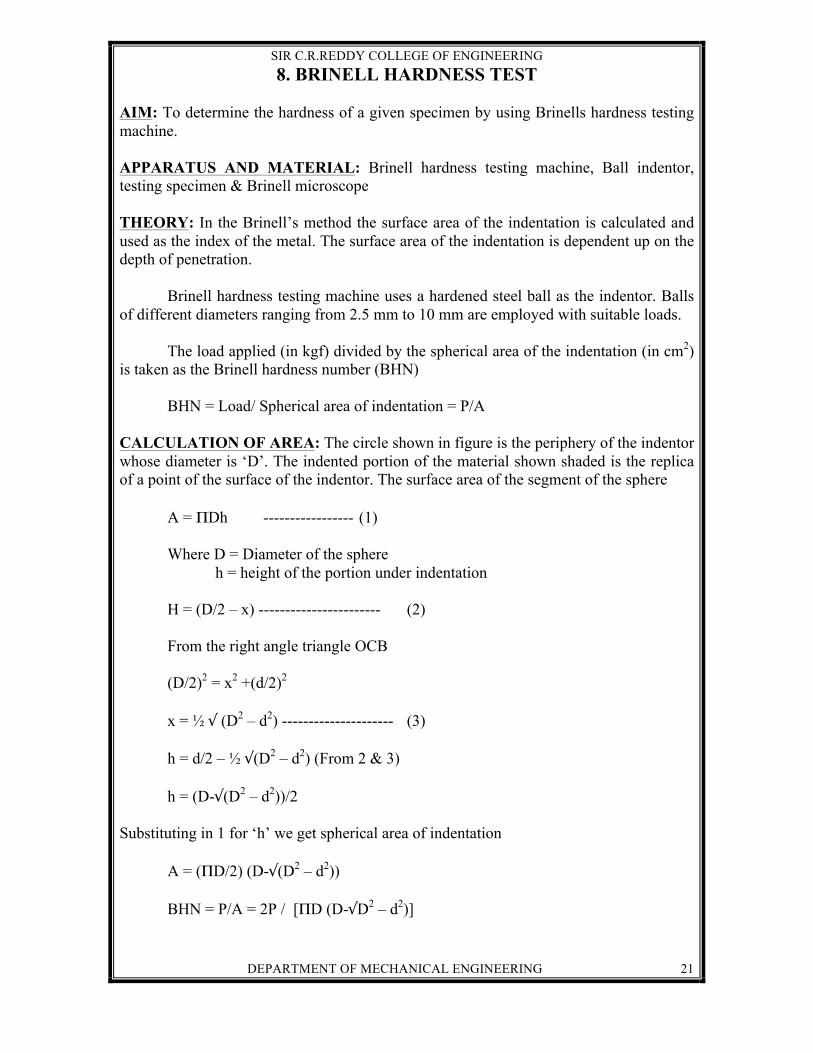
8. BRINELL HARDNESS TEST AIM: To determine the hardness of a given specimen by using Brinells hardness testing machine. APPARATUS AND MATERIAL: Brinell hardness testing machine, Ball indentor, testing specimen & Brinell microscope THEORY: In the Brinell’s method the surface area of the indentation is calculated and used as the index of the metal. The surface area of the indentation is dependent up on the depth of penetration. Brinell hardness testing machine uses a hardened steel ball as the indentor. Balls of different diameters ranging from 2.5 mm to 10 mm are employed with suitable loads. The load applied (in kgf) divided by the spherical area of the indentation (in cm2) is taken as the Brinell hardness number (BHN) BHN = Load/ Spherical area of indentation = P/A CALCULATION OF AREA: The circle shown in figure is the periphery of the indentor whose diameter is ‘D’. The indented portion of the material shown shaded is the replica of a point of the surface of the indentor. The surface area of the segment of the sphere A = ΠDh ----------------- (1) Where D = Diameter of the sphere h = height of the portion under indentation H = (D/2 – x) ----------------------- (2) From the right angle triangle OCB (D/2)2 = x2 +(d/2)2 x = ½ √ (D2 – d2) --------------------- (3) h = d/2 – ½ √(D2 – d2) (From 2 & 3) h = (D-√(D2 – d2))/2 Substituting in 1 for ‘h’ we get spherical area of indentation A = (ΠD/2) (D-√(D2 – d2)) BHN = P/A = 2P / [ΠD (D-√D2 – d2)]

SIR C.R.REDDY COLLEGE OF ENGINEERING
DEPARTMENT OF MECHANICAL ENGINEERING 22
PROCEDURE: 1. Select the proper size of the ball indenter and load to suit the material under test.
2. Mount the selected ball indenter
3. Mount the test specimen surface at right angles to the axis of the ball indenter plunger
4. Turn the hand wheel until the specimen makes solid contact with the indenter
5. Apply the load for a minimum of losses (for steel and hard materials)
6. Remove the load
7. Turn the hand wheel to bring down the anvil and test piece
8. Pick up the specimen from the anvil and place the microscope on the surface properly
and read the diameter of indentation across the ridge formed and read it.
9. Turn the microscope through 900 and take diameter again
10. Calculate the value of Brinell hardness number
11. Repeat the experiment at other portions of the test piece
PRECAUTIONS:
1. The surface of the test piece should be clear and smooth 2. The distance of the indentation from the edge of the test piece and also the distance
between two adjacent indentation should be at least 2.5 times the diameter of the indentation.
OBSERVATIONS:
S.No Material Diameter of indentor
(D) cm
Applied load (P) kgf
Diameter of indentation BHN Kgf/cm2 d1
cm
d2 cm
d = (d1+d2)/2
RESULT:
The Brinell hardness of 1) Aluminum = __________ kgf/cm2
2) Copper = ___________ kgf/cm2
3) Brass = ______________ kgf/cm2

SIR C.R.REDDY COLLEGE OF ENGINEERING
DEPARTMENT OF MECHANICAL ENGINEERING 23
VIVA QUESTIONS
1. What are the equipment and materials required for Brinell hardness test?
2. What is the purpose of microscope used in Brinell hardness test?
3. The surface area of indentation ‘A’ is dependent upon---?
4. What is the material used for ball indenter in case of Brinell hardness test?
5. What is the range of the size of ball indenter in case of Brinell hardness test?
6. What are the units for BHN?
7. What precautionary measures should be taken for the Brinell hardness test?
8. While mounting the test specimen the surface of the test specimen should be at---
to the axis of the ball indenter plunger?

SIR C.R.REDDY COLLEGE OF ENGINEERING
DEPARTMENT OF MECHANICAL ENGINEERING 24
9. VICKERS HARDNESS TEST AIM: To determine the hardness of a given specimen by using Vickers hardness testing machine. APPARATUS REQUIRED: Vickers hardness testing machine, diamondindenter. THEORY: The Vickers pyramid hardness test utilises a quadrilateral diamond pyramid with an angle of 1360 between the opposite faces, so that it is usable over the whole range of material hardness, give the diamond is the hardest known substance. This test is performed with varying loads on the indenter. More over the adoption of the square base pyramid shape provides freedom from distortion under load. In this testing very fine and very small size of the indentation is obtained, therefore specimen needs a glossy surface finish for testing. After the indentation diagonal of the indentation is accurately measured with the help of a microscope fitted on the tester. The diagonal is measure by focusing a cross wire device in the optical equipment. OBSERVATIONS: Diameter of indentation is ___________________ mm CALCULATION:
nindentatioat pyramid theof a are SurfacedLoadapplieVHN =
Surface area of indentation ⎟⎠
⎞⎜⎝
⎛=2s.a4A
Where s = Slant height of each of the four triangular faces
a = Side of the base of the pyramid = 2D
So area of indentation, S.D22s
2D4A =××=
More over 68Sin2aS =
68Sin2Da
68Sin2aD2AreaA ==∴
a
D

SIR C.R.REDDY COLLEGE OF ENGINEERING
DEPARTMENT OF MECHANICAL ENGINEERING 25
D – Dia of indentation A – Side of the base of the pyramid
Substituting a = 2D
22 DP854.1
854.1DP
APVHN ×
===∴
PRECAUTIONS:
1. The load should be choosen on the indenter depending upon the type of material used.
2. One should wait for 15 seconds, after applying the load through the pedal, so that the edges of the indentation are well defined.
3. Metal surface should be lightly polished. RESULT: The VHN of the given steel specimen is ________________
VIVA QUESTIONS
1. List out the mechanical properties?
2. Define hardness?
3. What are the shapes of indenters usually used for hardness tests?
4. What are the materials generally used for indenter?
5. What is the principle involved in vicker’s hardness test?
6. What are the precautions that should be taken in Vickers hardness test?

SIR C.R.REDDY COLLEGE OF ENGINEERING
DEPARTMENT OF MECHANICAL ENGINEERING 26
10. ROCKWELL HARDNESS TEST AIM: To determine the hardness of a given specimen by using Rockwell hardness testing macine. APPARATUS: Rockwell hardness testing machine, ball indenter. THEORY: Hardness is the resistance offered by a material for indentation. Hardness is a
very important property since the manufacturing depends on it to a great extent.
This is an indentation test to measure the hardness of a material normally. The test
involves a ball, a cone or a pyramid of harder material, which is indented into the
material under test with a specific load. The permanent indentation thus made is
measured to give an indentation of the hardness.
In this test spheroconical ball indenter of 1200 angle and spherical apex of radius
0.2m is used to make the indentation and the depth of indentation ‘t’ is used as a criteria
to calculate the hardness number. The Rockwell hardness number R is given by R = 100
– 500t. Depending on the load used for indentation there are number of scales A,B,C etc
available in this test. These are used for different materials with different hardness values.
In Rockwell B test steel ball of 0.0625inch diameter is used with a load of 100 kg. This
test is normally used for low and medium carbon steels. It should not be used for
materials whose hardness is above this value. This is the most fastest way of measuring
hardness because the hardness is directly read from scale on the Rockwell tester.
PROCEDURE: 1. Remove the clamping device by rotating it in anti clockwise direction and fix the
diamond cone indenter.
2. Adjust the load selector wheel for desired load and keep the lever in off position. 3. The given specimen with smooth surface is placed on the platform centrally and the
anvil is raised till the indenter above it comes into contact with the specimen. 4. The anvil is rotated further till small pointer on the dial comes to ‘set’ position which
indicates that minor load is applied. 5. Set the lever pointer to B-30 or C-0 position by rotating the wheel.
6. The required major load is applied by changing the lever to load position, slowly to bring the total load into action.
7. The long pointer of the dial gauge slowly moves and reaches a steady position. 8. Take back the lever to off position slowly.

SIR C.R.REDDY COLLEGE OF ENGINEERING
DEPARTMENT OF MECHANICAL ENGINEERING 27
9. The pointer now shows the final reading which is recorded and indicated as “Rockwell Hardness Number”
10. The test is repeated at different places on the surface of the specimen and the average is taken as the Rockwell hardness number.
OBSERVATIONS:
Trial Numb
er Material Tested
Scale Readin
g B/C
Indenter used
Major load (kg)
Rockwell Hardness number
Average
1 2 3
1 2 3
1 2 3
RESULT:
The Rockwell Hardness of Aluminium is ___ The Rockwell Hardness of Brass is ___
The Rockwell Hardness of Copper is ___ VIVA QUESTIONS
1. List out the mechanical properties?
2. Define hardness?
3. What is the principle involved in Rockwell hardness test?
4. What are the shapes of Indenters usually used for hardness tests?
5. What are the materials generally used for indenter?
6. What does HRB mean?
7. What does HRC mean?
8. What type of materials are used for test specimens in Hardness tests?
9. What precautions should be taken in case of Rockwell hardness test?
10. What is the minimum distance between the centres of the two adjacent
indentations ?
11. What is the minimum thickness of the test piece in case of Rockwell hardness
test?

SIR C.R.REDDY COLLEGE OF ENGINEERING
DEPARTMENT OF MECHANICAL ENGINEERING 28
11. SPRING TEST AIM: To determine the rigidity modulus of 1) Closed coil helical spring
2) Open coil helical by spring test. APPARATUS: Spring test machine, Micrometer, Vernier callipers, open & closed coil helical springs. THEORY: SPRING INDEX:
Spring index is defined as the ratio of the mean diameter of the coil to the diameter of wire.
C = Dm/d
Where Dm – mean diameter of the coil
d – diameter of wire. SPRING CONSTANT: Spring constant is defined as the load required per unit deflection of the spring.
K = w/δ
Where w – load δ - deflection of the spring
MODULUS OF RIGIDITY: It is the ratio of shear stress to shear strain
G = 8wDm3n/ δd4
Where w- load applied Dm – mean diameter of coil n – No. of turns in the spring δ - deflection of spring d – diameter of the wire
PROCEDURE: 1. Measure the diameter of spring by means of vernier callipers or by micrometer
2. Measure spring coil diameter by means of vernier calliper
3. Calculate mean diameter of the coil
4. Count the no. of turns in the spring
5. Load the spring by a suitable weight and note the corresponding axial deflection
reading.

SIR C.R.REDDY COLLEGE OF ENGINEERING
DEPARTMENT OF MECHANICAL ENGINEERING 29
PRECAUTIONS: 1. Load should be applied gradually
2. Number of turns should be counted carefully
3. The spring wire diameter should be measured accurately
4. Readings should be taken carefully
OBSERVATIONS: (1) OPEN COIL HELICAL SPRING: Coil diameter = D = _____ mm
Wire diameter = d = _____ mm
Mean diameter = Dm = D – d = ____ mm
No. of turns = n = ____
Rigidity modulus = G = 8Dm3 wn / δ d4
Initial deflection = δ = ____ mm
S.No Load (W)
kg
Deflection δ (mm) Rigidity modulus G(kg/mm2) Observed
Actual
Average = SPRING CONSTANT K: K = (F2 – F1) / (X2 – X1) = __________ kg/mm (2) CLOSED COIL HELICAL SPRING:
Coil diameter = D = ____ mm Wire diameter = d = _____ mm
Mean diameter = Dm = D – d = ____ mm
No. of turns = n = ____
Rigidity modulus = G = 8Dm3 wn / δ d4
SPRING CONSTANT K:

SIR C.R.REDDY COLLEGE OF ENGINEERING
DEPARTMENT OF MECHANICAL ENGINEERING 30
K = (F2 – F1) / (X2 – X1) = __________ kg/mm Initial deflection = δ = ____ mm S.No Load
(W) kg
Deflection δ (mm) Rigidity modulus G(kg/mm2)
Observed Actual
Average = RESULT: 1. Spring constant of open coil helical spring K = ______ kg / mm
2. Spring constant of closed coil helical spring K = _____ kg / mm
3. Rigidity modulus of open coil helical spring = G = _____ kg/mm2
4. Rigidity modulus of closed coil helical spring = G = ______ kg / mm2
VIVA QUESTIONS
1. What do you mean by a spring? 2. What are the important functions of a spring? 3. What are the common materials by which springs are made? 4. List out types of springs? 5. What do you understand by a helical spring? 6. What is the difference between a closed coil helical spring and open coil helical
spring? 7. What types of stresses are involved in leaf springs? 8. What type of spring is used to transmit a small torque? 9. What are the important applications of leaf springs? 10. If two springs of stiffness K1&K2 are connected in parallel then what is the
equivalent stiffness? 11. What do you mean by spring stiffness? 12. What is a spring index?
SIR C.R.REDDY COLLEGE OF ENGINEERING
DEPARTMENT OF MECHANICAL ENGINEERING 31
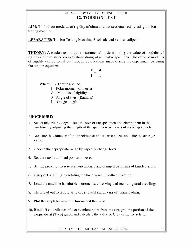
12. TORSION TEST AIM: To find out modulus of rigidity of circular cross sectional rod by using torsion testing machine. APPARATUS: Torsion Testing Machine, Steel rule and vernier calipers THEORY: A torsion test is quite instrumental in determining the value of modulus of rigidity (ratio of shear stress to shear strain) of a metallic specimen. The value of modulus of rigidity can be found out through observations made during the experiment by using the torsion equation.
LG
JT θ=
Where T - Torque applied J – Polar moment of inertia G – Modulus of rigidity
θ - Angle of twist (Radians) L – Gauge length.
PROCEDURE:
1. Select the driving dogs to suit the size of the specimen and clamp them in the machine by adjusting the length of the specimen by means of a sliding spindle.
2. Measure the diameter of the specimen at about three places and take the average
value. 3. Choose the appropriate range by capacity change lever. 4. Set the maximum load pointer to zero. 5. Set the protector to zero for convenience and clamp it by means of knurled screw. 6. Carry out straining by rotating the hand wheel in either direction. 7. Load the machine in suitable increments, observing and recording strain readings. 8. Then load out to failure as to cause equal increments of strain reading. 9. Plot the graph between the torque and the twist. 10. Read off co-ordinates of a convenient point from the straight line portion of the
torque-twist (T - θ) graph and calculate the value of G by using the relation
SIR C.R.REDDY COLLEGE OF ENGINEERING
DEPARTMENT OF MECHANICAL ENGINEERING 32
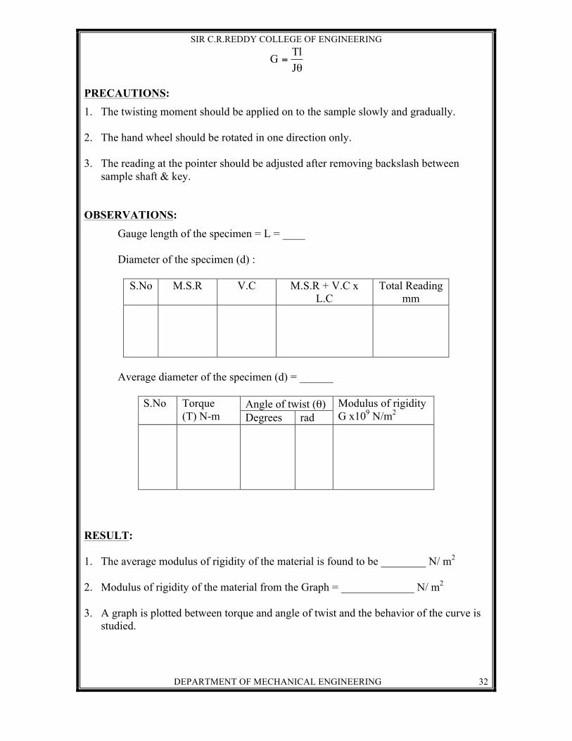
θ=JTlG
PRECAUTIONS: 1. The twisting moment should be applied on to the sample slowly and gradually. 2. The hand wheel should be rotated in one direction only. 3. The reading at the pointer should be adjusted after removing backslash between
sample shaft & key. OBSERVATIONS:
Gauge length of the specimen = L = ____ Diameter of the specimen (d) :
S.No M.S.R V.C M.S.R + V.C x L.C
Total Reading mm
Average diameter of the specimen (d) = ______
S.No Torque (T) N-m
Angle of twist (θ) Modulus of rigidity G x109 N/m2 Degrees rad
RESULT: 1. The average modulus of rigidity of the material is found to be ________ N/ m2 2. Modulus of rigidity of the material from the Graph = _____________ N/ m2 3. A graph is plotted between torque and angle of twist and the behavior of the curve is
studied.

SIR C.R.REDDY COLLEGE OF ENGINEERING
DEPARTMENT OF MECHANICAL ENGINEERING 33
VIVA QUESTIONS
1) What do you mean by modulus of rigidity?
2) What is shear strain?
3) Give the expression for the basic torsion equation?
4) What do you mean by polar moment of inertia?
5) What is polar modulus?
6) What is the expression for polar modulus of a circular shaft?
7) What do you mean by torsional rigidity?
8) Give the expression for power transmitted by a shaft?
9) What are the precautions that should be taken during torsion test?
10) Between which parameters a graph is plotted in case of torsion test?