sistema di scorrimento complanare coplanar sliding system file/slider-m.pdf · regolazione:...
TRANSCRIPT

sist
ema
di s
corri
men
to c
ompl
anar
eco
plan
ar s
lidin
g sy
stem

the Company
Opening, sliding, closing: this is the
source of Bortoluzzi Sistemi’s ideas.
The search for technology solutions
for closing and sliding system for
furnishing elements. Such ideas are
developed at our design engineering
department and later realized in
the production department through
continually updating information
technology and skilled technical
professionals. An organization that
allows to manufacture both standard
products and custom solutions
according to customer specifications.
A completely controlled production
process that is based on design
ideas and developed with technical
rigour. The result: avant-garde
solutions meeting the specific
customer requirements and a product
that provides technical reliability,
timely service and unique designs.
das Unternehmen
Öffnen, laufen, schließen: daher
stammen die Ideen von Bortoluzzi
Sistemi. Aus der Suche nach
Technologielösungen zum Schließen
und Laufen von Möbel- und Einrich
tungsbauelementen. Diese Ideen
werden von unsere technische
Abteilung entworfen und später
durch eine ständig entwickelte
Informationsstruktur und erfahrenes
Fachpersonall im Produktionsbereich
umgesetzt. Eine Organisation, die
sowohl Standardprodukte als auch
Lösungen nach Maß, die sich nach
den Kundenanforderungen richten,
anfertigt.Ein komplett kontrolliertes
Produktionsverfahren, was aus
Entwurfideen entstaht und auf einer
technischen Entwicklungsgenauigkeit
beruht. Das Ergebnis: High-End
Lösungen, die den spezifischen
Kundenanforderungen
entgegenkommen und ein Produkt,
das technische Zuverlässigkeit,
rechtzeitigen Kundendienst und
exklusive Entwürfe gewährleistet.
l’Azienda
Aprire, scorrere, chiudere: da
qui nascono le idee di Bortoluzzi
Sistemi. Dalla ricerca di soluzioni
tecnologiche per sistemi di chiusura
di mobili ed elementi d’arredo.
Idee che vengono sviluppate nel
nostro ufficio progettazione e
si concretizzano poi nel reparto
produttivo, grazie a personale
tecnico altamente specializzato e
a strutture informatiche in continuo
aggiornamento. Un percorso
produttivo controllato in ogni
sua fase, che nasce da intuizioni
progettuali e si sviluppa sostenuto
da rigore tecnico. Risultato: soluzioni
d’avanguardia in linea con le
specifiche esigenze del committente
e un prodotto garantito da affidabilità
tecnica, puntualità di servizio ed
esclusività progettuale.

SLIDER 1
Colonne verticali / Vertical columns / Vertikalen säulen
È UN MOVIMENTO SCORREVOLE PER DUE ANTE DI UGUALE LARGHEZZA A CHIUSURA COMPLANARE CHE TROVA APPLICAZIONE SU COLONNE VERTICALI.
IT IS A SLIDING MOVEMENT FOR TWO WING WITH THE SAME SIZE, COPLANAR LOCK, THAT CAN BE APPLIED ON VERTICAL COLUMNS.
ES HANDELT SICH UM EIN SCHIEBESYSTEM FÜR ZWEI GLEICHBREITE TÜREN MIT FLÄCHEN BÜNDIGE, BEWEGUNG DIE NACH KONFIGURATION AUF VERTIKALEN SÄLEN EINSETZBAR SIND.
MOVIMENTO COMPLANARE A DUE ANTETWO DOOR COMPLANATE SYSTEM / ZWEITÜRIGE, FLÄCHENBÜNDIGE SCHIEBESYSTEM

Bortoluzzi Sistemi2
Scheda tecnica del prodotto / Product technical sheet / Technische Beschreibung
I movimenti sono composti da:• profili in alluminio: lega 6060T5
anodizzati argento ARC 10• guide per l’uscita delle ante: MDF
rivestito con finitura superficiale tipo alluminio
• ruote di scorrimento: cuscinetti per alta velocità rivestiti in materiale plastico
• componenti di traslazione e regolazione: pressofusi in zama primaria 13
I movimenti possono montare ante che hanno le seguenti caratteristiche:• peso massimo per singola anta: kg 35• larghezza: minima mm 600 -
massima mm 1800 • altezza massima consigliata: mm
2200• spessore: minimo mm 18 - massimo
mm 45 (maniglia compresa) • materiale:
a) legno o derivati b) vetro con telaio in alluminio
(interpellare la ditta produttrice per verificare la fattibilità)
Pulizia dei movimenti: la pulizia dei componenti deve essere eseguita con acqua e sapone mediante un panno morbido. Evitare prodotti contenenti solventi e prodotti abrasivi.
Smaltimento: una volta dismesso, il prodotto o i suoi componenti non vanno dispersi nell’ambiente, ma conferiti ai sistemi pubblici di smaltimento.
The systems include:• steel profiles: 6060t5 alloy, anodized
ARC 10 silver • guides for wing extraction: MDF with
aluminium-like surface finishing• sliding wheels: plastic-coated bearings
for high-speed performance• translation and adjustment parts: die-
cast components in basic Zn+Al+Mg 13 alloy
The systems are suitable for the following door types:• max. weight for each door: kg 35• width: min. mm 600 – max. mm1800 • maximum recommended height: mm
2200• thickness.: min. mm18 - max. mm45• materials:
a) wood or derived material b) glass with steel frame (please
contact the manufacturer for feasibility)
System cleaning: the system’s parts can be cleaned with a soft cloth using water and soap. Do not use any solvents or abrasive products.
Disposal: the product and its components must not be disposed of in the environment; for disposal please use public disposal systems.
Die Schiebesysteme bestehen aus folgende Einbauteilen:• Aluprofile: aus 6060T5 Legierung,
eloxiert, Silber ARC 10• Schienen für die Öffnung der Türflügel:
MDF mit Oberfläche aus Aluminium unmzutett.
• Schieberollen: plastikbezogene Hoch-geschwindigkeitslager
• Einstell- und Verschiebungselemente: aus 13-Zamakdruckguss
Die Schiebesysteme eignen sich für Türen mit folgende Eigenschaften:• Max. Gewicht für jede Tür: Kg 35• Breite: min. mm 600 - max. mm 1800 • Empfohlene maximale Höhe: 2200
mm• Dicke: min. mm18 - max. mm 45
(inklusive Griffhöhe)• Stoff:
a) Holz oder Holzprodukte b) Glas mit Aluprofile umrahmt (für die
Machbarkeit wenden Sie sich bitte an den Hersteller)
Systemsreinigung: Ein weiches Tuch mit etwas Wasser und Seife ist das beste Reinigungsmittel für die Einbauteile. Verwenden Sie keine Chemikalien, aggressive Fleckenmittel oder Scheürmittel.
Entsorgung: Produkte und Produkteile, die nicht mehr zum Einsatz kommen, sollen nicht in die Umwelt gelangen und sind über in speziell dafür eingerichteten Sammelstellen zu entsorgen.

SLIDER 3
Tipologie aperture:• Sono disponibili movimenti con
apertura di due ante uguali oppure di un’anta unica su vano a giorno o cassetti
• L’apertura delle ante è prevista tramite l’ausilio di maniglie posizionate al centro del mobile
Per aperture particolari non previste contattare direttamente l’azienda produttrice.
Nota: L’azienda produttice si riserva il diritto di apportare modifiche tecniche senza preavviso.
Openings types:• Systems with two identical wings
or single wing opening to an open shelving unit or to a unit provided with drawers are available
• To open the wings you can use a handle mounted in the middle of the cabinet
For special opening types please contact the manufacturer.
Note: The manufacturer reserves the right to modify any product without prior notice.
Öffnungstypen:• Entweder Systeme mit zwei
gleichbreiten Türen oder mit einer einzigen Tür, die sich auf einen offenen Raum oder ein Fach öffnen
• Die Türöffnung erfolgt durch Handgriffe, die inmitten der Möbeltür montiert sind
Sollten Sie spezielle Öffnungen brauchen, wenden Sie sich direkt an den Hersteller.
Änderungen an den Produkten können vom Hersteller ohne Vorankündigung vorgenommen werden.
Scheda tecnica del prodotto / Product technical sheet / Technische Beschreibung
Bortoluzzi Sistemi4
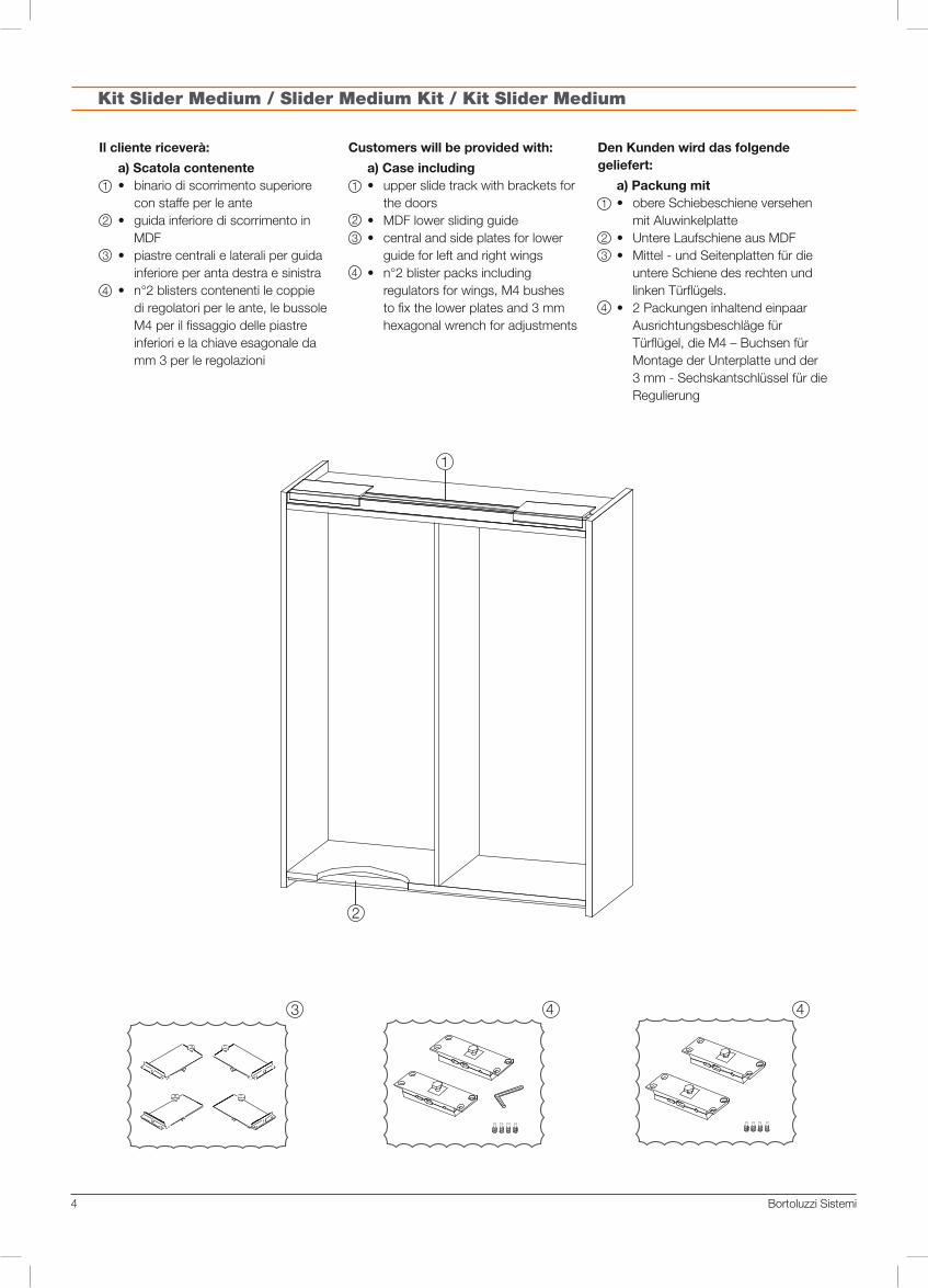
Kit Slider Medium / Slider Medium Kit / Kit Slider Medium
Il cliente riceverà:
a) Scatola contenente • binario di scorrimento superiore
con staffe per le ante• guida inferiore di scorrimento in
MDF• piastre centrali e laterali per guida
inferiore per anta destra e sinistra• n°2 blisters contenenti le coppie
di regolatori per le ante, le bussole M4 per il fissaggio delle piastre inferiori e la chiave esagonale da mm 3 per le regolazioni
Customers will be provided with:
a) Case including • upper slide track with brackets for
the doors• MDF lower sliding guide• central and side plates for lower
guide for left and right wings• n°2 blister packs including
regulators for wings, M4 bushes to fix the lower plates and 3 mm hexagonal wrench for adjustments
Den Kunden wird das folgende geliefert:
a) Packung mit • obere Schiebeschiene versehen
mit Aluwinkelplatte• Untere Laufschiene aus MDF• Mittel - und Seitenplatten für die
untere Schiene des rechten und linken Türflügels.
• 2 Packungen inhaltend einpaar Ausrichtungsbeschläge für Türflügel, die M4 – Buchsen für Montage der Unterplatte und der 3 mm - Sechskantschlüssel für die Regulierung

SLIDER 5
TIPOLOGIA A: Movimento con meccanismo di scorri-mento superiore per ante a ridosso su cielo, base e spalle esterne.
TYPE A: System with upper slide mechanism for doors covering top, bottom and side panels.
TYP A: System mit oberem Schiebesystem für Türöffnung ver oberen, Unteren und aussenseiten stehend.
TIPOLOGIA B: Movimento con meccanismo di scor-rimento superiore per ante a ridosso su cielo, base e in luce tra le spalle esterne.
TYPE B: System with upper slide mechanism for doors covering top panel, bottom and with side panels visible.
TYP B: System mit oberem Schiebesystem für Türöffnung var Ober- und Unter-platte und nach innen zu den Aussen-seiten.
Tipologie Slider Medium / Slider Medium types / Typologien Slider Medium

Bortoluzzi Sistemi6
Spazio minimo per fissaggio piastre inferiori mm 35Minimum gap for lower plate fixing mm 35Minimalraum für die Montage der mm 35 - Unterplatten
TIPOLOGIA “A”TYPE A / TYP A
MOVIMENTO CON MECCANISMO DI SCORRIMENTO SUPERIORE PER ANTE A RIDOSSO SU CIELO, BASE E SPALLE ESTERNE.
SYSTEM WITH UPPER SLIDE FORDOORS COVERING TOP, BOTTOM AND SIDE PANELS.
SYSTEM MIT OBEREM SCHIEBE-SYSTEM FÜR TÜRÖFFNUNG, VOR OBER, UNTER UND AUSSENSEITEN STEHEND.
��
���
��
���
��
���
��
��� �
���
��
��
����
��
�
����
���
��

SLIDER 7
��� ������
��
��� �� �� ���
��� ��
����������
���� ����
���� ����
��
��� ������
��
��� �� �� ���
��� ��
����������
���� ����
���� ����
��
Apertura ante/Door opening/Türöffnung
TIPOLOGIA “A”TYPE A / TYP A
Piedino lateraleSide footSeitlicher Sockelfuss
Piedino lateraleSide foot
Seitlicher Sockelfuss
Piedino centraleCentral foot
Mittelfuß

Bortoluzzi Sistemi8
TIPOLOGIA “B”TYPE B / TYP B
��
���
��
���
��
���
��
�
���
��
����
��
��
�
���
���
����
���
��
spazio minimo per fissaggio piastre inferiori mm 35Minimum gap for lower plate fixing mm 35Minimalraum für die Montage der mm 35 - Unterplatten
MOVIMENTO CON MECCANISMO DI SCORRIMENTO SUPERIORE PERANTE A RIDOSSO SU CIELO, BASE E IN LUCE TRA LE SPALLE ESTERNE.
SYSTEM WITH UPPER SLIDE FORDOORS COVERING TOP, BOTTOM AND WITH SIDE PANELS VISIBLE.
SYSTEM MIT OBEREM SCHIEBE-SY-STEM FÜR TÜRÖFFNUNG VON OBER UND UNTERPLATTE UND NACH INNEN ZU DEN AUSSENSEITEN.

SLIDER 9
TIPOLOGIA “B”TYPE B / TYP B
Apertura ante/Door opening/Türöffnung
��� ������
��
�� ��
�
����������
�� ��� �
���� ����
��������
��
��� ������
��
�� ��
�
����������
�� ��� �
���� ����
��������
��
Piedino lateraleSide footSeitlicher Sockelfuss
Piedino lateraleSide foot
Seitlicher Sockelfuss
Piedino centraleCentral foot
Mittelfuß

Bortoluzzi Sistemi10
Montaggio Slider Medium / Slider Medium assembly / Montage Slider Medium
Mettere in bolla il contenitore sul quale va applicato il sistema di scorrimento SLIDER MEDIUM (vedi fig. 100).
fig. 100
fig. 101
Level the cabinet which the sliding system SLIDER MEDIUM is to be applied to (see fig. 100).
Die Oberschrankstruktur, auf dem das Schiebesystem SLIDER MEDIUM eingesetzt werden soll, ausrichten(s. Bild 100).
Applicare il movimento SLIDER MEDIUM e fissarlo al cielo con viti a legno TPSdi adeguata lunghezza nei fori già predisposti sul movimento (vedi fig. 101).
Install the SLIDER MEDIUM system and fasten it to the ceiling with suitably long TPS wooden screws into holes in the mechanism (see fig. 101).
Das SLIDER MEDIUM system einsetzen und an der Decke durch angemessene TPS - Holzschrauben in der dafür vorbereiteten löchern befestigen(s. Bild 101).

SLIDER 11
Applicare la guida inferiore in MDF sotto il basamento e fissarla, con viti a legno TPS di lunghezza adeguata, dall’interno del mobile (fig. 102) o da sotto (fig.103) a seconda della scelta al momento dell’ordine (variabile “base”).
Montaggio Slider Medium / Slider Medium assembly / Montage Slider Medium
fig. 103
Apply the MDF lower guide under the base and fix it - using TPS wooden screws with suitable length - from inside (fig.102) or from beneath (fig.103) the cabinet, on account of the version selected (‘BASE’ variable).
Die untere MDF – Schiene unter der Bodenplatte befestigen und mit entsprechend langen, TPS – Holzschrauben in Innenschrank (Fig. 102) oder von unten (Fig. 103) fixieren – je nach Wahl zum Zeitpunkt der Bestellung (Variable ‚BASE’).
fig. 102

Bortoluzzi Sistemi12
Montaggio Slider Medium / Slider Medium assembly / Montage Slider Medium
Nel caso di ante in legno, inserire il regolatore verticale nella sede laterale e quello orizzontale-verticale nella sede centrale delle ante.Fissarli poi con viti a legno TPS di lunghezza adeguata allo spessore delle ante (vedi fig. 104).Nel bordo inferiore delle ante, inserire nei fori predisposti, le bussole M4 in dotazione, per il fissaggio delle piastre.
In case of wooden wings, insert the vertical governor into the central slot and the horizontal-vertical governor into the wing side slot.Then tighten use TPS wooden screws with a length suitable to the wing thickness (please refer to fig.104).Insert the M4 bushes supplied into the special holes in the edges of lower wings to fix plates.
In Fall von Holztüren, muss der vertikale Ausrichtungsbeschlag am seitlichen Sitz und der horizontal – vertikale am mittleren Sitz der Türflügel angebracht werden.Die Ausrichtungsbeschläge mit angemessenen TPS – Holzschrauben, befestigen (siehe Fig.104).Am unteren Rand der Türflügel werden die mitgelieferten M4-Buchsen in die dafür vorgesehenen Öffnungen eingeführt, um die Platten zu fixieren.
Nel caso di ante con telaio in alluminio, inserire il regolatore verticale nella sede laterale e quello orizzontale-verticale nella sede centrale delle ante.Fissarli poi con viti TPS autofilettanti per metallo (vedi fig. 105).Nel bordo inferiore delle ante, dovranno essere predisposti filetti M4 o inserti filettati M4, nelle posizioni indicate dagli elaborati della Bortoluzzi Sistemi, per il fissaggio delle piastre.
In case of aluminium frame wings, insert the vertical governor into the side slot and the horizontal-vertical governor into the wing central slot.Then tighten using TPS self-tapping screws for metal with a suitable length (see fig.105).To fix plates, M4 threads or M4 threaded insets shall be provided in the lower edges of wings, according to the positions stated in Bortoluzzi Sistemi’s documents.
Sollten die Türflügel einen Aluminiumrahmen haben, wird der vertikale Ausrichtungsbeschlag in den seitlichen Sitz und der horizontal – vertikale in den mittleren Sitz der Türflügel eingeführt.Dann werden die Ausrichtungsbeschläge mit entsprechenden selbstschneidenden TPS – Schrauben für Metall befestigt. (siehe Fig.105).Am unteren Rand der Türflügel müssen für die Fixierung der Platten M4 – Gewindegänge vorgerichtet oder M4 – Gewinde eingeführt werden – für die korrekte Positionieren befolgen Sie dabei bitte die Anweisungen, die Sie in den Unterlagen Bortoluzzi Sistemi finden.
fig. 105
regolatore verticalevertical adjuster
senkrechter Ausrichtbeschlag
regolatore orizzontale e verticalehorizontal and vertical adjustersenkrechter und waagerechter Ausrichtbeschlag
regolatore verticalevertical adjuster
senkrechter Ausrichtbeschlag
fig. 104
regolatore orizzontale e verticalehorizontal and vertical adjustersenkrechter und waagerechter
Ausrichtbeschlag

SLIDER 13
Estrarre una staffa superiore aprendola fino a fine corsa.Applicare la corrispondente anta agganciando la testa esagonale della vite sporgente dal regolatore centrale nella sede ricavata sulla staffa (fig. 106). Poi ruotare leggermente l’anta fino a far entrare la testa esagonale della vite sporgente dal regolatore laterale nell’altra sede della staffa (vedi fig. 106).Quindi, con una chiave fissa da mm10, serrare le due viti a testa esagonale(vedi fig. 107)
Montaggio Slider Medium / Slider Medium assembly / Montage des Oberschrank
Extract one of the upper bracket and open it to the stop position.Apply the corresponding wing by clamping the hexagonal head of the screw protruding from the central governor to the central slot in the bracket (fig.106). Then gently rotate the wing until the hexagonal head of the screw protruding from the side governor enters the other bracket slot (fig.106).Then tighten the hexagonal head screws using a mm 10 wrench (fig.107).
Einen der oberen Führungswinkel abnehmen und ihn bis zum Anschlag öffnen.Den dazugehörigen Türflügel aufsetzen, indem der sechskantige Schraubenkopf, der vom zentralen Ausrichtungsbeschlag absteht, in die dafür vorgesehene Öffnung am Führungswinkel gesetzt wird (Fig.106). Dann wird der Türflügel leicht gedreht, bis der sechskantige Schraubenkopf, der vom seitlichen Ausrichtungsbeschlag absteht, in die andere Öffnung am Führungswinkel einspringt. (Fig.106).Mit einem 10 mm – Maulschlüssel die beiden sechskantigen Schrauben fest anziehen (Fig.107).
fig. 106
Sede per vite, regolatore centraleScrew slot, central governorSchraubloch, mittlerer Ausrichtungsbeschlag
Sede per vite, regolatore lateraleScrew slot, side governorSchraubloch, seitlicher Ausrichtungsbeschlag
fig. 107

Bortoluzzi Sistemi14
Ripetere lo stesso procedimento con la piastra laterale infilando, in questo caso, il cuscinetto nel binario anteriore della guida (vedi fig. 109).
Montaggio Slider Medium / Slider Medium assembly / Montage des Oberschrank
fig. 108
Der gleiche Arbeitsvorgang wird mit der Seitenplatte wiederholt, wobei hier das Lager in die vordere Schiene eingeführt wird. (Fig. 109).
Repeat the process with the side wing (in this case insert the bearing into the front track of the guide - fig. 109).
Prendere le due piastre inferiori in dotazione (identificate da etichette) relative all’anta che si sta applicando.Infilare il cuscinetto di quella centrale nel binario posteriore della guida precedentemente avvitata sotto il basamento. Infilare la spina di posizionamento, presente nel bordo della piastra, nel foro di riferimento eseguito nel bordo inferiore dell’anta ed avvitare le due viti TBEI M4 in dotazione(vedi fig. 108).
Take the two lower plates supplied (identified by labels) corresponding to the wing being applied.Insert the bearing of the central wing into the rear track of the guide already screwed to the base. Insert the positioning pin on the plate edge into the reference hole drilled on the wing lower edge, and screw the two TBEI M4 screws supplied (fig.108).
Nehmen Sie die beiden mitgelieferten Unterplatten (mit Etiketten gekennzeichnet) für den Türflügel, der gerade montiert wird.Führen Sie das Lager der mittleren in die hintere Schiene, die vorher unter der Bodenplatte montiert wurde, ein. Jetzt wird der Positionierungsstift, der sich am Rand der Platte befindet, in die entsprechende Öffnung am unteren Rand des Türflügels eingesteckt, und dann fixiert man mit den beiden mitgelieferten TBEI – Schrauben(Fig. 108).
fig. 109
Binario posterioreRear trackHintere Laufschiene
Spina di posizionamentoPositioning pinPositionierungsstift
Binario anterioreFront trackVordere LaufschieneSpina di posizionamento
Positioning pinPositionierungsstift

SLIDER 15
Caso 1: anta non parallela alla struttura della colonna (vedi fig. 110). È necessario intervenire agendo sui regolatori verticali con la chiave esagonale da mm 3 in dotazione nell’impronta di sinistra(vedi fig.111).
Case 1: door not parallel to the cabinet structure (see fig. 110). Regulate vertical adjusters using the supplied 3 mm hexagonal key in the left groove(see fig106).
Fall 1: Tür nicht parallel zur Korposstruktur (s. Bild 110). Die senkrechte Ausrichtbeschläge sollen durch die 3 mm Sechskantschlüssel im linken Schlitz verstellt werden(s. Bild 106).
Regolazioni / Adjustments / Regulierung
fig. 110
fig. 111

Bortoluzzi Sistemi16
��
Regolazioni / Adjustments / Regulierung
Caso 2: scuretti tra le ante e le spalle di dimensioni non regolari (vedi fig. 112).É necessario intervenire sul regolatore orizzontale applicato al centro delle ante (vedi fig. 104-105) con la chiave esagonale da mm 3 in dotazione, nell’impronta di destra (vedi fig. 113)
fig. 113
fig. 112
Case 2: non regular-sized spaces between door and shoulders (see Figure 112). Regulate the horizontal adjuster mounted in the middle of the doors (see fig. 103) with the supplied 3 mm hexagonal key in the right grooves(see fig. 108).
Fall 2: Tür nicht parallel zur Korposstruktur (s. Bild 112). Die senkrechte Ausrichtbeschläge sollen durch die 3 mm Sechskantschlüssel im rechten Schlitz verstellt werden(s. Bild 113).

This table includes the variables required to
design the piece of furniture to which the
selected Slider Medium system applies.
Based on this information, Bortoluzzi Sistemi
will provide reports about the finishings to be
performed on the furniture panels.
Additional information is available on the
Website www.bortoluzzi.com/slider, where
you can view a 3D simulation of the finished
piece of furniture or define a purchase order.
LEGENDA CODICI E SPECIFICHE NECESSARIE PER L’ORDINELEGEND OF NECESSARY CODES AND SPECIFICATIONS FOR ORDERKODELEGENDE UND NÖTIGE DETAILS FÜR DIE BESTELLUNG
Nella presente tabella sono indicate le variabili
necessarie per la progettazione del mobile sul
quale applicare la tipologia di Slider Medium
prescelta.
Sulla base di tali informazioni Bortoluzzi Sistemi
fornirà gli elaborati riguardanti le lavorazioni da
eseguire sui pannelli del mobile.
Ulteriori informazioni sono disponibili sul sito
internet www.bortoluzzi.com/slider, dove
è anche possibile effettuare una simulazione
tridimensionale del mobile finito o perfezionare
l’ordine di acquisto.
Diese Tabelle listet die Variabeln auf, die zum
Entwurf des Möbelstückes für die Einsetzung des
ausgewählten Slider-Systems notwendig sind.
Aufgrund dieser Informationen wird Bortoluzzi
Sistemi Berichte über die Bearbeitungen, die
auf den Möbelplatten auszuführen sind, liefern.
Weitere Informationen finden Sie auf der
Webseite: www.bortoluzzi.com/slider, wo eine
3D-Möbelsimulation zur Verfügung steht und ein
Kaufauftrag erteilt werden kann.
COD.DESCRIZIONE VARIABILIDESCRIPTION OF VARIABLESMÖGLICHKEITEN
Tipologia A Tipologia B
LTLarghezza totale mobileTotal width of cabinetGesamter Schrankkorpusbreitenmass
• •
HTAltezza totale mobileTotal height of interior of cabinetGesamter Schrankkorpushöhenmass
• •
HIAltezza vano interno mobileHeight of interior of cabinetInnen Schrankkorpushöhe
• •
SPASpessore antaThickness of doorTürstärke
• •
SPAMSpessore anta + manigliaThickness of door + handleTürstärke + Griff
• •
SPBSpessore baseThickness of bottom panelUntere Korpusplattenstärke
• •
SPCSpessore cieloThickness of top panelObere Korpusplattenstärke
• •
SPESpessore spalla esternaThickness of side panelSeiten Korpusstärke
• •
SPISpessore spalla centraleThickness of centre panelMittelseite Korpusstärke
• •
SAESormonto anta su spalla esternaSuperimposition of door on side panelTür vor Aussenseiten
•
RMRientro maniglia dal bordo antaRecess of handle from edge of doorGriffabstand von seitliche Kante
• •
RASRientro anta dalla strutturaRecess of door from structureTürabstand von Struktur
•
AADistanza spalla centrale-anta in aperturaCentral shoulder-wing distance when openAbstand Mittelstruktur � geöffneter Türflügel
• •
DYPLDistanza fianco-piedino in profonditàSide-foot distance in depthTiefenmassiger Abstand Seitenstruktur � Fuß
• •
DXPLIngombro piedino dal fiancoFeet room on sideAusmaß Fuß aus seitlicher Ansicht
• •
BASEFissaggio guida inf. dall’interno del mobileLower guide fixing from within the cabinetMontage der unteren Führungsschiene vom Möbelinneren
SI / NO SI / NO
DAMPRientro anta ammortizzatoAmortized wing retractionGefederter Einzug Türflügel
SI / NO SI / NO

Bortoluzzi Sistemi srlVia Caduti 14.IX.44, n. 45
32100 BELLUNO - ItalyTel. 0437.930866 r.a.
www.bortoluzzi.com
02-2
006