skype and lync video capture specification · skype and lync video capture specification h100693...
TRANSCRIPT
Skype & Lync
Video Capture Specification
For devices using Skype/Lync’s video processing
Document Number: H100693
Release Date: August 2013
Disclaimer: This document is provided “as-is”. Information and views expressed in this document, including URL and
other Internet Web site references, may change without notice. You bear the risk of using it.
This document does not provide you with any legal rights to any intellectual property in any Microsoft product. You
may copy and use this document for your internal, reference purposes.
Feedback: You have no obligation to give Microsoft any suggestions, comments or other feedback ("Feedback")
relating to the materials herein (“Materials”). However, any Feedback you voluntarily provide may be used in Microsoft
products and related specifications or other documentation (collectively, "Microsoft Offerings") which in turn may be
relied upon by other third parties to develop their own products. Accordingly, if you do give Microsoft Feedback on any
version of these Materials or the Microsoft Offerings to which they apply, you agree: (a) Microsoft may freely use,
reproduce, license, distribute, and otherwise commercialize your Feedback in any Microsoft Offering; (b) you also grant
third parties, without charge, only those patent rights necessary to enable other products to use or interface with any
specific parts of a Microsoft product that incorporate your Feedback; and (c) you will not give Microsoft any Feedback
(i) that you have reason to believe is subject to any patent, copyright or other intellectual property claim or right of any
third party; or (ii) subject to license terms which seek to require any Microsoft Offering incorporating or derived from
such Feedback, or other Microsoft intellectual property, to be licensed to or otherwise shared with any third party.
© 2013 Microsoft Corporation. All rights reserved.
Skype and Lync Video Capture Specification
H100693 Page 2 of 68
Table of Contents 1 Revision History ................................................................................................................................ 5
2 Introduction ...................................................................................................................................... 6
2.1 Overview ....................................................................................................................................... 6
2.2 Performance levels ....................................................................................................................... 7
2.3 Definitions ..................................................................................................................................... 8
2.4 Classification of the products........................................................................................................ 9
Default testing position ......................................................................................................... 9
3 Entry criteria for video testing ........................................................................................................ 10
3.1 Video prerequisite testing .......................................................................................................... 10
E2E Scenarios: Video Sanity Tests ....................................................................................... 11
3.2 Driver ........................................................................................................................................... 12
Support USB Video Class (UVC) Driver ................................................................................ 12
Support USB Audio Class (UAC) Driver ................................................................................ 12
CPU usage ........................................................................................................................... 13
3.3 Basic video attributes .................................................................................................................. 14
Windows HCK video test must be passed ........................................................................... 14
Image resolutions, frame rates, color spaces ..................................................................... 14
UVC 1.5 compatibility for H.264 hardware encoding webcams ......................................... 17
3.4 Pre-conditions to enable testing the video quality requirements .............................................. 18
Anti-flicker solution ............................................................................................................. 18
Automatic white balance, exposure and gain ..................................................................... 18
Pixel aspect ratio ................................................................................................................. 18
Autofocus performance ...................................................................................................... 19
Verify cameras correct use of luminance and color spaces ................................................ 20
3.5 Other ........................................................................................................................................... 22
Embedded camera shipping protection .............................................................................. 22
Usage indicator ................................................................................................................... 22
4 Video quality requirements ............................................................................................................ 23
4.1 Image detail quality..................................................................................................................... 23
MTF ..................................................................................................................................... 23

Skype and Lync Video Capture Specification
H100693 Page 3 of 68
Oversharpening ................................................................................................................... 26
Edge roughness ................................................................................................................... 27
Depth of field ...................................................................................................................... 28
Texture acutance ................................................................................................................ 28
4.2 Noise ........................................................................................................................................... 30
Image spatial SNR ................................................................................................................ 30
Image temporal SNR ........................................................................................................... 31
4.3 Color quality ................................................................................................................................ 32
Gamma ................................................................................................................................ 32
Image dynamic range .......................................................................................................... 33
Relative illumination ........................................................................................................... 34
Color uniformity .................................................................................................................. 35
Veiling glare ......................................................................................................................... 36
Color accuracy ..................................................................................................................... 38
Color saturation .................................................................................................................. 39
Exposure accuracy ............................................................................................................... 39
White balance error ............................................................................................................ 40
4.4 Geometry .................................................................................................................................... 40
Field of view ........................................................................................................................ 40
Field of view consistency .................................................................................................... 42
Geometric distortion ........................................................................................................... 43
4.5 Timing .......................................................................................................................................... 44
System latency .................................................................................................................... 44
Jitter .................................................................................................................................... 45
Audio/video synchronization .............................................................................................. 45
Time to capture first image, change resolutions ................................................................ 46
Video latency during a call .................................................................................................. 46
Video frame rate during a call ............................................................................................. 47
5 Video test setup .............................................................................................................................. 48
Main video test setup ......................................................................................................... 48
Video latency test setup for system latency ....................................................................... 49
Video latency test setup – End to End ................................................................................ 49
Skype and Lync Video Capture Specification
H100693 Page 4 of 68
End to End testing over Skype video call ............................................................................ 50
Light setup and conditions .................................................................................................. 52
Test charts ........................................................................................................................... 56
Latency measurement kit ................................................................................................... 62
Other inventory ................................................................................................................... 63
6 Appendix ......................................................................................................................................... 64
6.1 Camera location interface ........................................................................................................... 64
6.2 Conference room camera criteria ............................................................................................... 65
Skype and Lync Video Capture Specification
H100693 Page 5 of 68
1 Revision History Revision Published Description
1.0
8/2013 First official release of the unified specification. Change list below refers to
changes from draft versions.
Modified ST-52 is not used. ST-52 may be used with shutters as in Skype
specification version 6.
Exposure accuracy test added back.
SNR improvement test is integrated into spatial noise requirements.
E27/A19 lights described.
Oversharpening requirement added in 200lux.
Geometric distortion requirement is revised.
New method to test 3.3.5.
Texture acuity algorithm revised and requirement relaxed.
Additional details provided in Sections 3.1, 3.3.4 and 5.
Based on Lync specification revision G and Skype specification version 6.
Skype and Lync Video Capture Specification
H100693 Page 6 of 68
2 Introduction
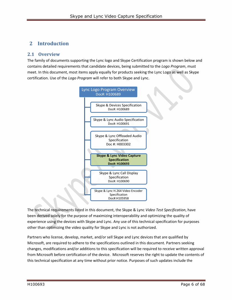
2.1 Overview The family of documents supporting the Lync logo and Skype Certification program is shown below and
contains detailed requirements that candidate devices, being submitted to the Logo Program, must
meet. In this document, most items apply equally for products seeking the Lync Logo as well as Skype
certification. Use of the Logo Program will refer to both Skype and Lync.
The technical requirements listed in this document, the Skype & Lync Video Test Specification, have
been derived solely for the purpose of maximizing interoperability and optimizing the quality of
experience using the devices with Skype and Lync. Any use of this technical specification for purposes
other than optimizing the video quality for Skype and Lync is not authorized.
Partners who license, develop, market, and/or sell Skype and Lync devices that are qualified by
Microsoft, are required to adhere to the specifications outlined in this document. Partners seeking
changes, modifications and/or additions to this specification will be required to receive written approval
from Microsoft before certification of the device. Microsoft reserves the right to update the contents of
this technical specification at any time without prior notice. Purposes of such updates include the
Lync Logo Program OverviewDoc#: H100689
Skype & Devices SpecificationDoc#: H100689
Skype & Lync Audio SpecificationDoc#: H100691
Skype & Lync Offloaded Audio Specification
Doc #: H003302
Skype & Lync Video Capture SpecificationDoc#: H100693
Skype & Lync Call Display Specification
Doc#: H100690
Skype & Lync H.264 Video Encoder Specification
Doc#:H105958
Skype and Lync Video Capture Specification
H100693 Page 7 of 68
capture of new capabilities in Skype and Lync platforms, new device categories, as well as performance
improvements in the hardware used in peripheral devices.
2.2 Performance levels This document provides performance requirements for Lync and Skype certified devices.
There are two levels of webcam performance defined by this specification:
Standard: Defines a good video quality level that, when achieved, allows use of both Skype and
Lync logos in association with the product.
Premium: Defines Skype and Lync’s preferred video quality level.
Skype and Lync Video Capture Specification
H100693 Page 8 of 68
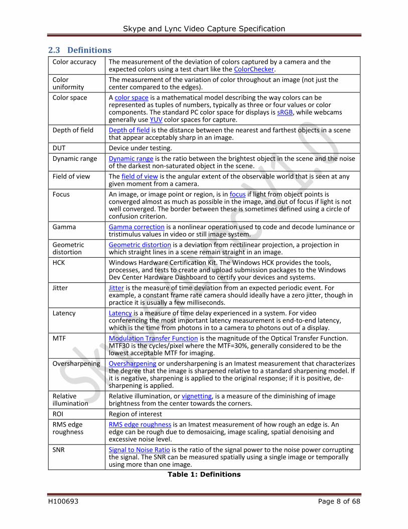
2.3 Definitions
Color accuracy The measurement of the deviation of colors captured by a camera and the expected colors using a test chart like the ColorChecker.
Color uniformity
The measurement of the variation of color throughout an image (not just the center compared to the edges).
Color space A color space is a mathematical model describing the way colors can be represented as tuples of numbers, typically as three or four values or color components. The standard PC color space for displays is sRGB, while webcams generally use YUV color spaces for capture.
Depth of field Depth of field is the distance between the nearest and farthest objects in a scene that appear acceptably sharp in an image.
DUT Device under testing.
Dynamic range Dynamic range is the ratio between the brightest object in the scene and the noise of the darkest non-saturated object in the scene.
Field of view The field of view is the angular extent of the observable world that is seen at any given moment from a camera.
Focus An image, or image point or region, is in focus if light from object points is converged almost as much as possible in the image, and out of focus if light is not well converged. The border between these is sometimes defined using a circle of confusion criterion.
Gamma Gamma correction is a nonlinear operation used to code and decode luminance or tristimulus values in video or still image system.
Geometric distortion
Geometric distortion is a deviation from rectilinear projection, a projection in which straight lines in a scene remain straight in an image.
HCK Windows Hardware Certification Kit. The Windows HCK provides the tools, processes, and tests to create and upload submission packages to the Windows Dev Center Hardware Dashboard to certify your devices and systems.
Jitter Jitter is the measure of time deviation from an expected periodic event. For example, a constant frame rate camera should ideally have a zero jitter, though in practice it is usually a few milliseconds.
Latency Latency is a measure of time delay experienced in a system. For video conferencing the most important latency measurement is end-to-end latency, which is the time from photons in to a camera to photons out of a display.
MTF Modulation Transfer Function is the magnitude of the Optical Transfer Function. MTF30 is the cycles/pixel where the MTF=30%, generally considered to be the lowest acceptable MTF for imaging.
Oversharpening Oversharpening or undersharpening is an Imatest measurement that characterizes the degree that the image is sharpened relative to a standard sharpening model. If it is negative, sharpening is applied to the original response; if it is positive, de-sharpening is applied.
Relative illumination
Relative illumination, or vignetting, is a measure of the diminishing of image brightness from the center towards the corners.
ROI Region of interest
RMS edge roughness
RMS edge roughness is an Imatest measurement of how rough an edge is. An edge can be rough due to demosaicing, image scaling, spatial denoising and excessive noise level.
SNR Signal to Noise Ratio is the ratio of the signal power to the noise power corrupting the signal. The SNR can be measured spatially using a single image or temporally using more than one image.
Table 1: Definitions
Skype and Lync Video Capture Specification
H100693 Page 9 of 68
2.4 Classification of the products This document applies to all PCs with integrated webcam and video peripheral devices for the PCs. The
described requirements are the same, but the differences in usage scenarios are considered when
positioning the device under testing in video lab.
In this document the following categories are distinguished:
Portable devices (with built-in cameras): laptops, tablets and other mobile devices running
Windows.
Desktop cameras: All-in-one solutions, external USB webcams, large displays with built-in
webcam.
Living room cameras: TVs and peripherals for TVs.
Conferencing cameras: meeting room solutions.
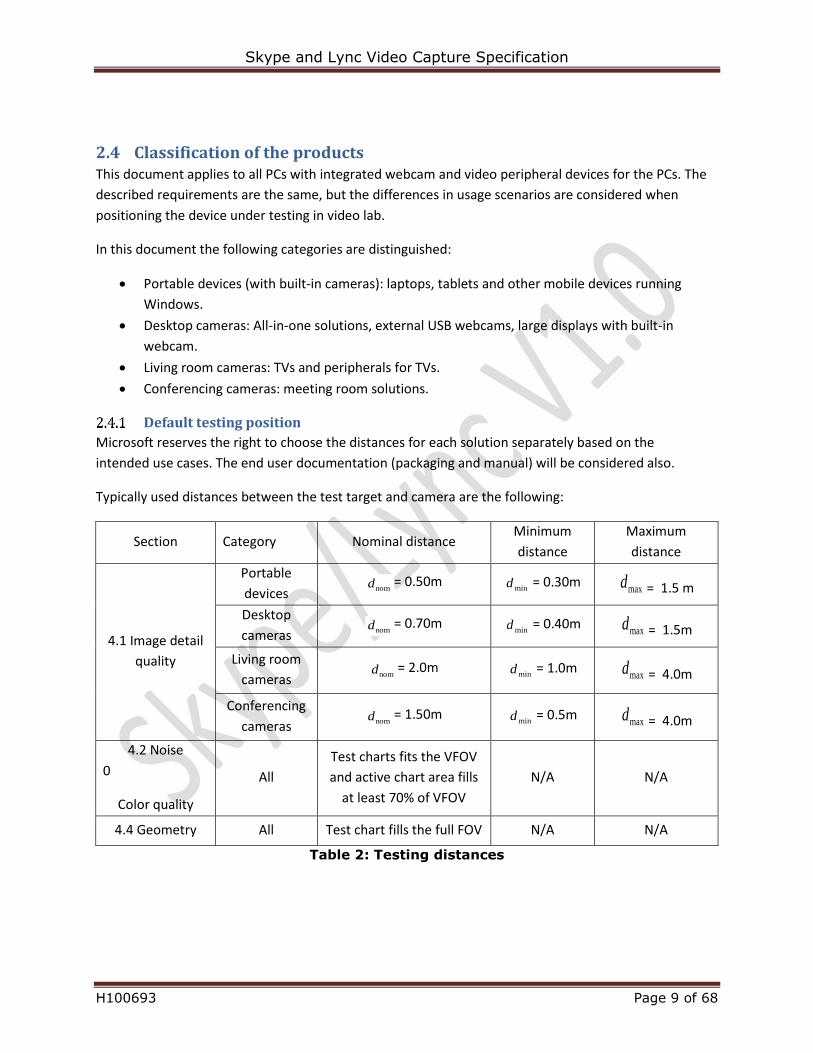
Default testing position
Microsoft reserves the right to choose the distances for each solution separately based on the
intended use cases. The end user documentation (packaging and manual) will be considered also.
Typically used distances between the test target and camera are the following:
Section Category Nominal distance Minimum
distance
Maximum
distance
4.1 Image detail
quality
Portable
devices nomd = 0.50m
mind = 0.30m maxd = 1.5 m
Desktop
cameras nomd = 0.70m
mind = 0.40m maxd = 1.5m
Living room
cameras nomd = 2.0m
mind = 1.0m maxd = 4.0m
Conferencing
cameras nomd = 1.50m
mind = 0.5m maxd = 4.0m
4.2 Noise
0
Color quality
All
Test charts fits the VFOV
and active chart area fills
at least 70% of VFOV
N/A N/A
4.4 Geometry All Test chart fills the full FOV N/A N/A
Table 2: Testing distances
Skype and Lync Video Capture Specification
H100693 Page 10 of 68
3 Entry criteria for video testing A solution submitted to testing must meet some essential requirements to enable the testing.
If any of the tested items in this chapter fails then the tester has the right to stop testing any further and
the test will be considered completed (and the test fees may not be refunded).
Battery powered devices are tested so that they are connected to external power supply.
3.1 Video prerequisite testing All devices shall be evaluated over Lync or Skype call at each engineering stage (e.g. by the OEM at
major internal milestones, and again by the test lab prior to beginning the quantitative testing). The goal
is to identify any obvious problems before beginning the quantitative testing.
The evaluation should be performed under well-lit office condition and simulated living room lighting
conditions. Lighting conditions for these sanity tests are intentionally less controlled (and slightly more
relaxed) than those for the formal quantitative tests because these are intended to be easy to execute,
with a focus on highlighting obvious issues that would be apparent to an average end user. All tests
below require two people. The term “near-end user” describes the person using the DUT and the term
“far-end user” describes the person in a remote room who is using a reference device to communicate
with the near-end user.
Well lit office environment:
Moderately sized room, with fluorescent overhead lights in the FOV behind the DUT user.
Lighting level is 125 lux plus or minus 50 lux using measured with the light meter sensor held at users face at face level of the DUT user facing the camera.
Examples of simulated living room conditions:
Reduced ambient light level is 40 lux plus or minus 20 lux using incandescent indirect lighting measured with the light meter at face level of the DUT user facing the camera. Incandescent indirect lighting example would be a floor standing Touchier lamp with either tungsten filament or halogen lamp with adjustable brightness. The lamp should be approximately 1.5 meters behind the user and visible in the field of view.
Far-end system requirements:
The far-end user is required to have a system capable of rendering the max resolution and supported by the camera (http://technet.microsoft.com/en-us/library/jj688132.aspx).
Good quality HD (1080p capable) monitor Test Score definitions scale
Test scoring will be done on a scale of 1 to 5, with a score of 1 being BAD and 5 being GOOD 5: No detectable flaws in the observed metric (Pass)
Skype and Lync Video Capture Specification
H100693 Page 11 of 68
4: Some minor flaws detectable by an observant user (Pass) 3: Flaws detectable to the casual user (Possible Fail further review required) 2: Serious flaws making the call difficult to continue (Fail) 1: Very serious flaws preventing the completion of the call (Fail)
E2E Scenarios: Video Sanity Tests
3.1.1.1 Video Render
1. With the DUT in well-light office environment, place an E2E Skype video call and later E2E Lync video call between the two users.
2. Begin the evaluation by opening video in both directions. Far end user will need to resize video image to achieve the maximum resolution of the DUT camera (720p or 1080p)
The far end user will observe and evaluate the video image for any image clarity flaws. i. Watch for texture based on natural features (e.g. ceiling tiles, user’s hair) and
test texture chart.
The far end user will observe and evaluate the video for encoding related artifacts. i. Watch for video jerkiness – stalling or skipping video frames.
ii. Watch for image blockiness. iii. Watch for other encoding artifacts like blurring, color bleeding, staircase effect,
ringing, false contouring, and mosquito effect.
The far end user will observe and evaluate the video image for any image color flaws. i. Watch for skin tone, walls, and light coming from light fixture.
ii. Watch for disturbing color noise levels. 3. Turn the lights off and on while creating as little physical movement on the scene as possible.
Check if the image is restored correctly (without artifacts, correct colors, no significant noise additions).
4. Repeat step 2 in living room simulated environment.
3.1.1.2 Image Motion
1. With the DUT in normal usage environment, place an E2E Skype video call and later E2E Lync video call between the two users.
2. Begin the evaluation by opening video in both directions. Near end user to waive hand as sanity check for Jitter. Near end user to Clap hands as sanity check for A/V sync.
Far-end user to watch for Jitter during hand wave.
Far-end user to watch for A/V sync during hand clap.
Far-end user to verify sufficient frame rate at various resolutions. 3. Repeat step 2 in low light stress environment.
Skype and Lync Video Capture Specification
H100693 Page 12 of 68
3.2 Driver This section applies to external USB webcams.
Support USB Video Class (UVC) Driver
3.2.1.1 Purpose
Webcams should be fully functional with default Windows drivers. Note all tests in this specification
need to be run with the default Windows drivers as well as the OEM drivers (if supplied to the end user
with a product).
3.2.1.2 Requirements
If the webcam uses USB bus it must support the UVC standard 1.0 or later versions and work with
standard Windows UVC drivers.
3.2.1.3 Test procedure
Run Device Manager and check if the webcam is using the Windows UVC driver usbvideo.sys and that
the driver provider is Microsoft. If the driver is not the Windows UVC driver, roll back the driver to the
Windows UVC driver.
Support USB Audio Class (UAC) Driver
3.2.2.1 Purpose
USB webcams should be fully functional with default Windows drivers. If the webcam has a microphone
built-in then it must work with UAC driver.
3.2.2.2 Requirements
If the USB webcam has built-in microphone then it must support the UAC standard 1.0 and later and
work with standard Windows drivers.
3.2.2.3 Test procedure
Run Device Manager and check if the webcam is using the Windows UAC driver usbaudio.sys and the
provider is Microsoft. If the driver is not the Windows UAC driver, roll back the driver to the Windows
UAC driver.
Skype and Lync Video Capture Specification
H100693 Page 13 of 68
CPU usage
3.2.3.1 Purpose
Makes sure the webcam driver (not standard UVC/UAC drivers), which includes any video processing, do
not cause excessive CPU usage. Only the CPU usage of OEM drivers are measured, not the Windows in-
box UVC/UAC drivers.
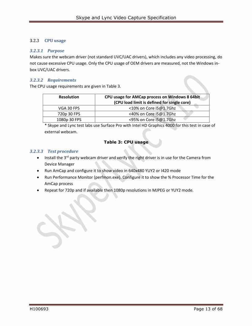
3.2.3.2 Requirements
The CPU usage requirements are given in Table 3.
* Skype and Lync test labs use Surface Pro with Intel HD Graphics 4000 for this test in case of
external webcam.
Table 3: CPU usage
3.2.3.3 Test procedure
Install the 3rd party webcam driver and verify the right driver is in use for the Camera from
Device Manager
Run AmCap and configure it to show video in 640x480 YUY2 or I420 mode
Run Performance Monitor (perfmon.exe). Configure it to show the % Processor Time for the
AmCap process
Repeat for 720p and if available then 1080p resolutions in MJPEG or YUY2 mode.
Resolution CPU usage for AMCap process on Windows 8 64bit (CPU load limit is defined for single core)
VGA 30 FPS <10% on Core [email protected]
720p 30 FPS <40% on Core [email protected]
1080p 30 FPS <95% on Core [email protected]
Skype and Lync Video Capture Specification
H100693 Page 14 of 68
3.3 Basic video attributes
Windows HCK video test must be passed
3.3.1.1 Purpose
The Windows Hardware Certification Kit (HCK) video test is verifying several essential video attributes
that are necessary for conducting the video tests in this document. It also covers certain areas that are
left out of this specification.
3.3.1.2 Requirements
Solution that are sold with Windows pre-installed or have Windows OS marked as a supported operating
system must pass the testcases in Windows HCK video test. The passed test report must be provided
before the testing is started.
3.3.1.3 Test process
Verify that the HCK video test report is submitted.
Make sure that the report is matching with the product. In case of any doubt about the HCK video report
the tester must rerun the HCK test to verify.
Image resolutions, frame rates, color spaces
3.3.2.1 Purpose
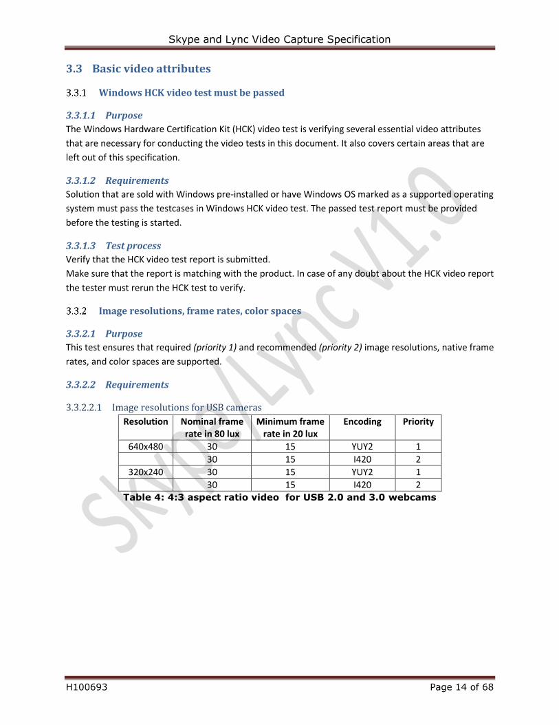
This test ensures that required (priority 1) and recommended (priority 2) image resolutions, native frame
rates, and color spaces are supported.
3.3.2.2 Requirements
3.3.2.2.1 Image resolutions for USB cameras
Resolution Nominal frame rate in 80 lux
Minimum frame rate in 20 lux
Encoding Priority
640x480 30 15 YUY2 1
30 15 I420 2
320x240 30 15 YUY2 1
30 15 I420 2 Table 4: 4:3 aspect ratio video for USB 2.0 and 3.0 webcams

Skype and Lync Video Capture Specification
H100693 Page 15 of 68
Resolution Nominal frame rate in 80 lux
Minimum frame rate in 20 lux
Encoding Priority
1920x1080 30 15 MJPEG or YUY2 1
1280x720 30 15 MJPEG or YUY2 1
30 15 I420 2
960x540 30 15 MJPEG or YUY2 1
30 15 I420 2
848x480 30 15 MJPEG or YUY2 1
30 15 I420 2
640x360 30 15 YUY2 1
30 15 I420 2
424x240 30 15 YUY2 1
30 15 I420 2
320x180 30 15 YUY2 1
30 15 I420 2 Table 5: 16:9 aspect ratio video for USB 2.0 HD webcams
Resolution Nominal frame rate in 80 lux
Minimum frame rate in 20 lux
Encoding Priority
1920x1080 30 15 YUY2 1
30 15 I420 2
1280x720 30 15 YUY2 1
30 15 I420 2
960x540 30 15 YUY2 1
30 15 I420 2
848x480 30 15 YUY2 1
30 15 I420 2
640x360 30 15 YUY2 1
30 15 I420 2
424x240 30 15 YUY2 1
30 15 I420 2
320x180 30 15 YUY2 1
30 15 I420 2 Table 6: 16:9 aspect ratio video for USB 3.0 HD webcams
3.3.2.2.2 Image resolutions for MIPI cameras
Resolution Nominal frame rate
in 80 lux
Minimum frame rate
in 20 lux
Encoding Priority
640x480 30 15 NV12 or I420 1
320x240 30 15 NV12 or I420 1 Table 7: 4:3 aspect ratio video for MIPI webcams
Skype and Lync Video Capture Specification
H100693 Page 16 of 68
Resolution Nominal frame rate
in 80 lux
Minimum frame rate
in 20 lux
Encoding Priority
1920x1080 30 15 NV12 or I420 1
1280x720 30 15 NV12 or I420 1
960x540 30 15 NV12 or I420 1
848x480 30 15 NV12 or I420 1
640x360 30 15 NV12 or I420 1
424x240 30 15 NV12 or I420 1
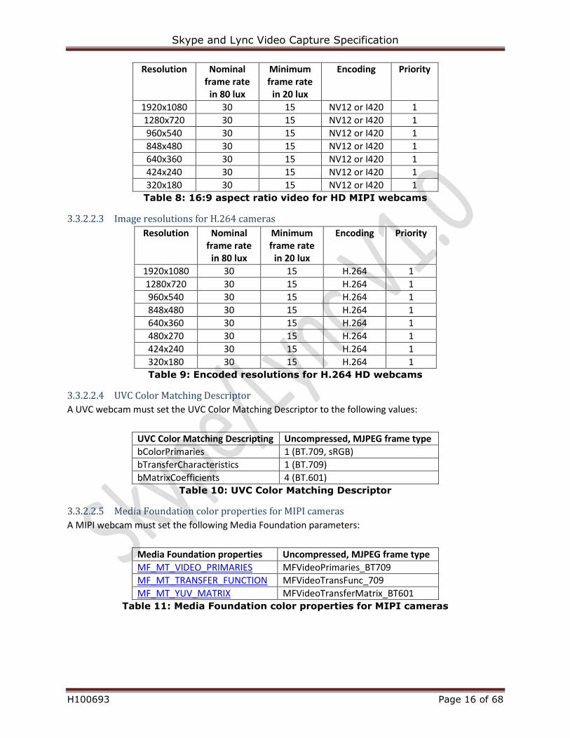
320x180 30 15 NV12 or I420 1 Table 8: 16:9 aspect ratio video for HD MIPI webcams
3.3.2.2.3 Image resolutions for H.264 cameras
Resolution Nominal frame rate
in 80 lux
Minimum frame rate
in 20 lux
Encoding Priority
1920x1080 30 15 H.264 1
1280x720 30 15 H.264 1
960x540 30 15 H.264 1
848x480 30 15 H.264 1
640x360 30 15 H.264 1
480x270 30 15 H.264 1
424x240 30 15 H.264 1
320x180 30 15 H.264 1 Table 9: Encoded resolutions for H.264 HD webcams
3.3.2.2.4 UVC Color Matching Descriptor
A UVC webcam must set the UVC Color Matching Descriptor to the following values:
UVC Color Matching Descripting Uncompressed, MJPEG frame type
bColorPrimaries 1 (BT.709, sRGB)
bTransferCharacteristics 1 (BT.709)
bMatrixCoefficients 4 (BT.601) Table 10: UVC Color Matching Descriptor
3.3.2.2.5 Media Foundation color properties for MIPI cameras
A MIPI webcam must set the following Media Foundation parameters:
Media Foundation properties Uncompressed, MJPEG frame type
MF_MT_VIDEO_PRIMARIES MFVideoPrimaries_BT709
MF_MT_TRANSFER_FUNCTION MFVideoTransFunc_709
MF_MT_YUV_MATRIX MFVideoTransferMatrix_BT601 Table 11: Media Foundation color properties for MIPI cameras
Skype and Lync Video Capture Specification
H100693 Page 17 of 68
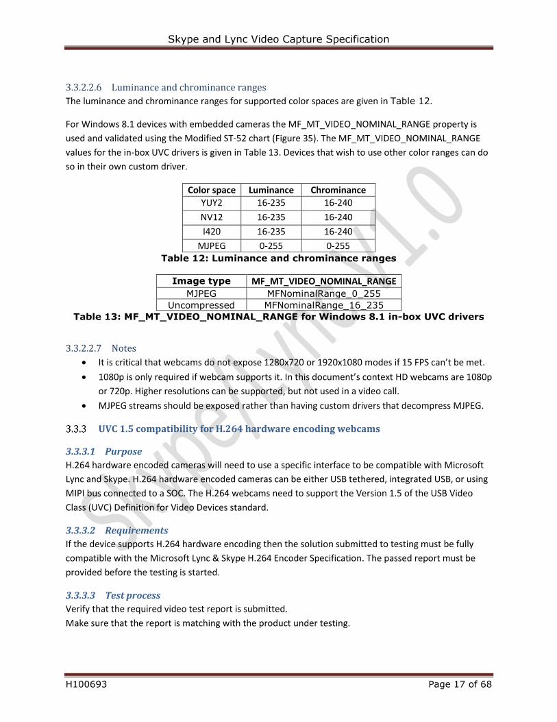
3.3.2.2.6 Luminance and chrominance ranges
The luminance and chrominance ranges for supported color spaces are given in Table 12.
For Windows 8.1 devices with embedded cameras the MF_MT_VIDEO_NOMINAL_RANGE property is
used and validated using the Modified ST-52 chart (Figure 35). The MF_MT_VIDEO_NOMINAL_RANGE
values for the in-box UVC drivers is given in Table 13. Devices that wish to use other color ranges can do
so in their own custom driver.
Color space Luminance Chrominance
YUY2 16-235 16-240
NV12 16-235 16-240
I420 16-235 16-240
MJPEG 0-255 0-255 Table 12: Luminance and chrominance ranges
Image type MF_MT_VIDEO_NOMINAL_RANGE
MJPEG MFNominalRange_0_255
Uncompressed MFNominalRange_16_235
Table 13: MF_MT_VIDEO_NOMINAL_RANGE for Windows 8.1 in-box UVC drivers
3.3.2.2.7 Notes
It is critical that webcams do not expose 1280x720 or 1920x1080 modes if 15 FPS can’t be met.
1080p is only required if webcam supports it. In this document’s context HD webcams are 1080p
or 720p. Higher resolutions can be supported, but not used in a video call.
MJPEG streams should be exposed rather than having custom drivers that decompress MJPEG.
UVC 1.5 compatibility for H.264 hardware encoding webcams
3.3.3.1 Purpose
H.264 hardware encoded cameras will need to use a specific interface to be compatible with Microsoft
Lync and Skype. H.264 hardware encoded cameras can be either USB tethered, integrated USB, or using
MIPI bus connected to a SOC. The H.264 webcams need to support the Version 1.5 of the USB Video
Class (UVC) Definition for Video Devices standard.
3.3.3.2 Requirements
If the device supports H.264 hardware encoding then the solution submitted to testing must be fully
compatible with the Microsoft Lync & Skype H.264 Encoder Specification. The passed report must be
provided before the testing is started.
3.3.3.3 Test process
Verify that the required video test report is submitted.
Make sure that the report is matching with the product under testing.
Skype and Lync Video Capture Specification
H100693 Page 18 of 68
3.4 Pre-conditions to enable testing the video quality requirements The requirements in this chapter are to ensure the feasibility and reliability of automated tests
described in Section 4. The automatically adjusted image parameters (such as gain and white balance)
must stabilize within 5 seconds after change of scene or light conditions. If the camera has auto focus,
the focus should also stabilize to focused image in less than 5 seconds.
Anti-flicker solution
3.4.1.1 Purpose
Imaging in lighting powered by 50 or 60 Hz mains frequency can result in flicker that significantly
degrades SNR (> 8 dB). The camera has to be able to suppress this effect in captured video. This is
especially important for notebook computers that may travel between 50 and 60 Hz countries.
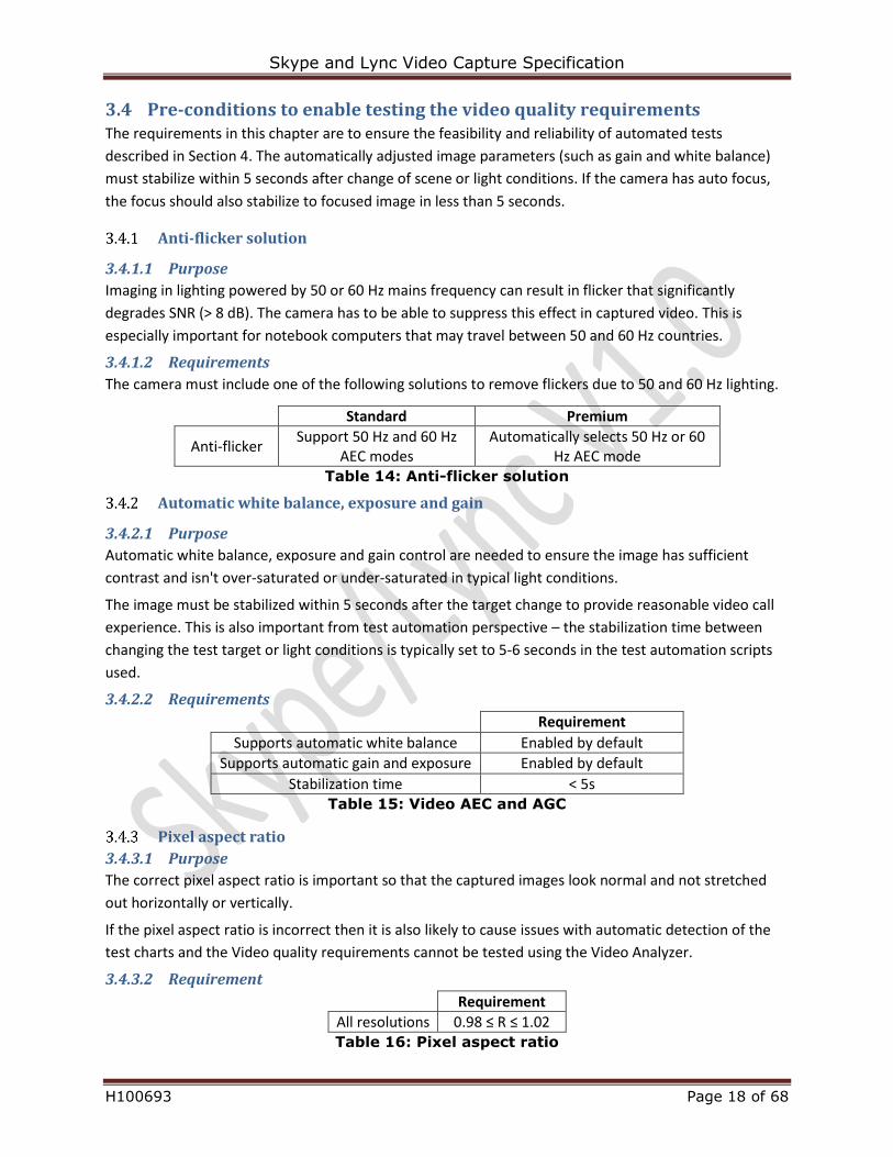
3.4.1.2 Requirements
The camera must include one of the following solutions to remove flickers due to 50 and 60 Hz lighting.
Standard Premium
Anti-flicker Support 50 Hz and 60 Hz
AEC modes Automatically selects 50 Hz or 60
Hz AEC mode Table 14: Anti-flicker solution
Automatic white balance, exposure and gain
3.4.2.1 Purpose
Automatic white balance, exposure and gain control are needed to ensure the image has sufficient
contrast and isn't over-saturated or under-saturated in typical light conditions.
The image must be stabilized within 5 seconds after the target change to provide reasonable video call
experience. This is also important from test automation perspective – the stabilization time between
changing the test target or light conditions is typically set to 5-6 seconds in the test automation scripts
used.
3.4.2.2 Requirements
Requirement
Supports automatic white balance Enabled by default
Supports automatic gain and exposure Enabled by default
Stabilization time < 5s Table 15: Video AEC and AGC
Pixel aspect ratio
3.4.3.1 Purpose
The correct pixel aspect ratio is important so that the captured images look normal and not stretched
out horizontally or vertically.
If the pixel aspect ratio is incorrect then it is also likely to cause issues with automatic detection of the
test charts and the Video quality requirements cannot be tested using the Video Analyzer.
3.4.3.2 Requirement
Requirement
All resolutions 0.98 ≤ R ≤ 1.02 Table 16: Pixel aspect ratio
Skype and Lync Video Capture Specification
H100693 Page 19 of 68
Autofocus performance
3.4.4.1 Purpose
This requirement specifies autofocus performance and manual focus API support (for cameras with
autofocus). Most webcams with autofocus experience “focus swimming” and sometimes get stuck in an
unfocused state. The typical desktop scenario doesn’t need autofocus, as the camera’s depth of field at
the nominal distance is sufficient. To minimize focus swimming, the autofocus performance is specified
in a real-world test. To allow Microsoft Lync and Skype to programmatically specify manual focus, the
application must be able to switch off autofocus through api and set it to default focal distance.
3.4.4.2 Requirements
1. Autofocus performance: Images must be focused 99% of the time over 5 minutes in a typical
use-case scenario.
2. Manual-focus performance: The default distance for manual focus must be equal to the nominal
distance for the matching category as described in Section 2.4.1. This allows manual focus to be
used to eliminate focus swimming and ensures that users are in focus in most desktop and
notebook scenarios. The default manual focus MTF30 must be with 15% relative error to the
autofocus MTF30.
3. If the auto-focus cannot be manually disabled, it must adapt to changes of the test target or
lighting within 5 seconds.
3.4.4.3 Test procedure
1. Choose the testing area the following way:
Only overhead lighting without any sunlight – on the table in front of the tester it should be
around 300 lux.
The background should be neutral colors. The tester should avoid wearing clothing with high
frequencies (i.e. no stripes thinner than 25mm / 1 inch.
Use two tilted edge printouts on either side of the persons head (above shoulders). These will
be used to determine if the image in respective frame is in focus. Having the edges on either
side should help make sure that there is at least one visible on all frames. The tilted edges are
no farther than 30cm (1 feet) behind the tester.
2. Set up the camera at nominal distance from the tester.
3. Record a simulated 5 minute video call.
4. Measure the time while autofocus was automatically being adjusted. If there was a period when the
autofocus was set incorrectly then this time should be added to the measured time.
Also, take a note in case the autofocus was not adapting within 5 seconds in any occurrence.
1. Set up the solution at nominal distance from the SFRplus chart.
2. Find manually the best focus setting for the center of the chart. Calculate the average MTF30 of the
4 edges in the center of the chart with the Video Analyzer.
3. Manually offset the focus to an extreme and enable autofocus.
4. Once the autofocus is stabilized calculate the MTF30 values again and compare the average with
previously found average.
Skype and Lync Video Capture Specification
H100693 Page 20 of 68
Verify cameras correct use of luminance and color spaces
3.4.5.1 Purpose
The luminance range of video render for Skype and Lync is 0 to 255.
As listed in sections 3.3.2.2.4 and 3.3.2.2.5 a camera should represent 0..255 luminance and
chrominance levels in MJPEG mode, but Luminance 16-235 and Chrominance 16-240 in case of a raw
video mode (YUY2, NV12, I420). For raw video modes the Skype or Lync client does the stretching to full
RGB range during the video render.
3.4.5.2 Requirements
Requirement
Average luminance pixel value for “patch 36 (black)” when YUY transform is turned off in Remote Capture Tool
16 ≤ avg pixel value
Average luminance pixel value for “ patch 1 (white)” when YUY transform in Remote Capture Tool is turned off
avg pixel value ≤ 235
Table 17: min/max luminance level requirements
3.4.5.3 Test procedure
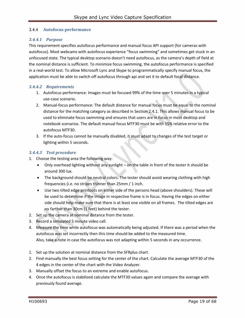
Test target ITDR-36 chart
ROI Patch 1 (white reference) / patch 36 (black reference)
Analysis Skype Certification Video Analyzer: automatic detection of the ROI and calculation of value
Table 18: min/max luminance level test details
Figure 1: Transmissive dynamic range test chart
Skype and Lync Video Capture Specification
H100693 Page 21 of 68
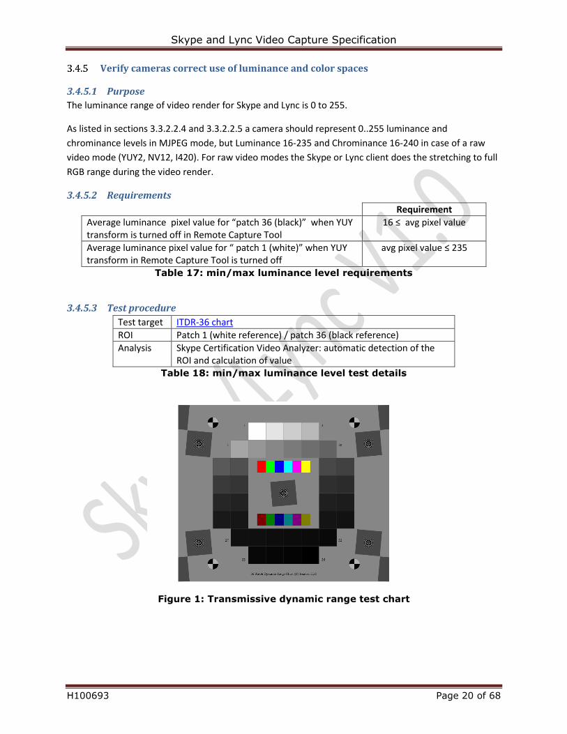
Use Remote capture tool – make snapshots for all raw video mode resolutions (YUY2, NV12,
I420) of ITDR-36 chart without the YUV transform enabled
Figure 2: YUV transform setting in RCT
Analyze the patch 1 and 36 for the average luminance level. The white level shall not exceed
pixel value 235
The black level shall not be below pixel value 16
If the values are above or below these thresholds it means the camera does not follow the
luminance and chrominance values correctly as listed in sections 3.3.2.2.4 and 3.3.2.2.5
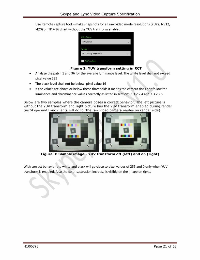
Below are two samples where the camera poses a correct behavior. The left picture is
without the YUV transform and right picture has the YUV transform enabled during render
(as Skype and Lync clients will do for the raw video camera modes on render side).
Figure 3: Sample image - YUV transform off (left) and on (right)
With correct behavior the white and black will go close to pixel values of 255 and 0 only when YUV
transform is enabled. Also the color saturation increase is visible on the image on right.
Skype and Lync Video Capture Specification
H100693 Page 22 of 68
3.5 Other
Embedded camera shipping protection
3.5.1.1 Purpose
Most notebook and desktop embedded cameras ship with a protective plastic cover. Some of these
covers are not noticeable by the user as they are clear and well aligned over the camera cover glass.
Since the user only sees a preview image they might not detect the degraded image quality.
3.5.1.2 Requirements
If the product ships with a protective lens cover then
o It is recommended that the shipping cover is colored (for example blue, to make it easy
to detect)
o Has a small lobe to allow easy removal with fingers
o Could have a written instruction such as “remove”
3.5.1.3 Test procedure
Examine the DUT’s protective plastic cover. It must not be clear and should include a “Remove” label or
icon.
Usage indicator
3.5.2.1 Purpose
This requirement lets the user know when the camera is on and imaging the user or off and not imaging
the user.
It is advised to either use a low power diffuse LED or add a diffusing glass/plastic in front of the LED. Too
bright indicator LED could disturb the user when he or she is looking direct at the camera in dark room.
3.5.2.2 Requirements
Requirement
Usage indicator Light on when capturing video
Light can be on when capturing audio (optional) Usage light off otherwise
Table 19: Usage indicator
3.5.2.3 Test procedure
For each P1 resolution and max frame rate:
Open and render the capture source. DUT usage indicator should be on.
Skype and Lync Video Capture Specification
H100693 Page 23 of 68
4 Video quality requirements This section defines video metrics that help ensure good-quality Windows video capture for UC.
In case a standalone webcam has a custom driver then it will tested two times – with UVC driver and
with the custom driver. All requirements must be met in both cases.
Webcams will be tested under all available P1 resolutions and color spaces unless specified otherwise. IF
the webcam has autofocus then this will be disabled for all tests except for the depth of field test.
The DUT is positioned as described Section 2.4.1 Default testing position.
4.1 Image detail quality These tests ensure that images provide a desired level of image acuity; for example, the lens is sharp
enough for the sensor, and the sensor has enough pixels to capture the desired resolution after
demosaicing and image processing.
MTF
4.1.1.1 Purpose
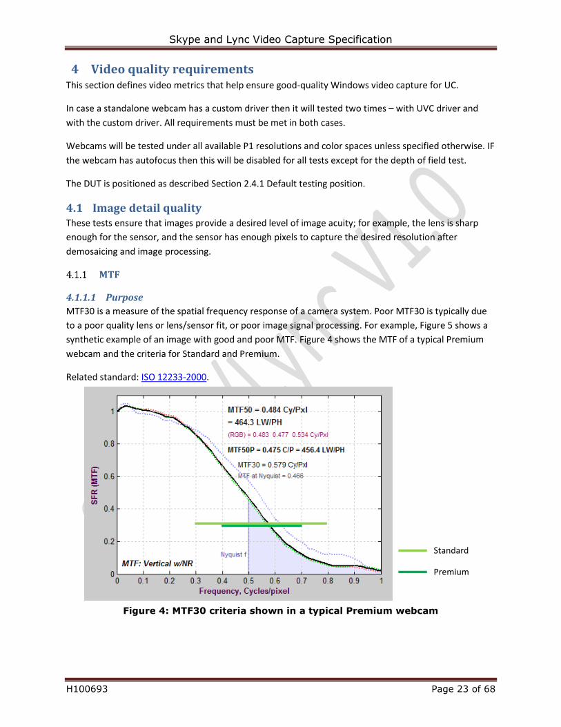
MTF30 is a measure of the spatial frequency response of a camera system. Poor MTF30 is typically due
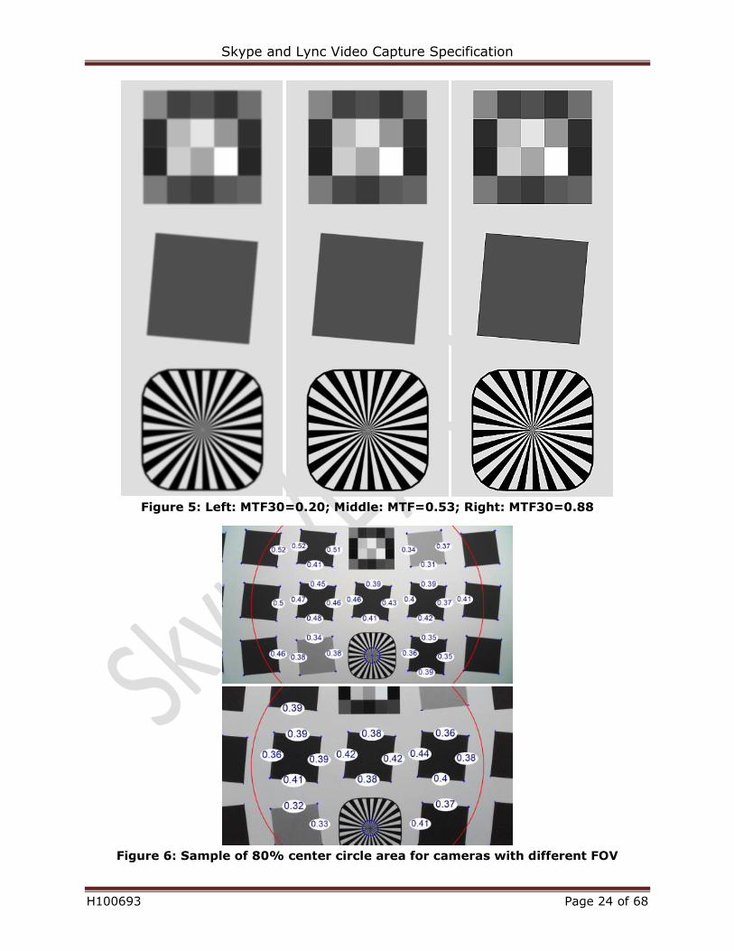
to a poor quality lens or lens/sensor fit, or poor image signal processing. For example, Figure 5 shows a
synthetic example of an image with good and poor MTF. Figure 4 shows the MTF of a typical Premium
webcam and the criteria for Standard and Premium.
Related standard: ISO 12233-2000.
Standard
Premium
Figure 4: MTF30 criteria shown in a typical Premium webcam
Skype and Lync Video Capture Specification
H100693 Page 24 of 68
Figure 5: Left: MTF30=0.20; Middle: MTF=0.53; Right: MTF30=0.88
Figure 6: Sample of 80% center circle area for cameras with different FOV
Skype and Lync Video Capture Specification
H100693 Page 25 of 68
4.1.1.2 Requirements
MTF30 Standard Premium
MTF30 (20lux 3000K LED, center) [0.3,0.8] [0.4,0.7]
MTF30 (80lux 3000K LED, center) [0.3,0.8] [0.4,0.7]
MTF30 (80lux 3000K LED, 80% center circle) N/A [0.3,0.7] Table 20: MTF requirements
4.1.1.3 Test procedure
Test target Default: SFR Plus (small) Alternate: SFR Plus (large) in case all corners fit into the wider ROI on SFR Plus (small)
ROI Center: 2 horizontal and 2 vertical edges in the middle of the SFR Plus chart Average: all complete edges within the wider ROI (circle with diameter equal to 80% of the width of the frame)
Analysis Skype Certification Video Analyzer: automatic detection of the ROI and calculation of value
Table 21: MTF test details
Skype and Lync Video Capture Specification
H100693 Page 26 of 68
Oversharpening
4.1.2.1 Purpose
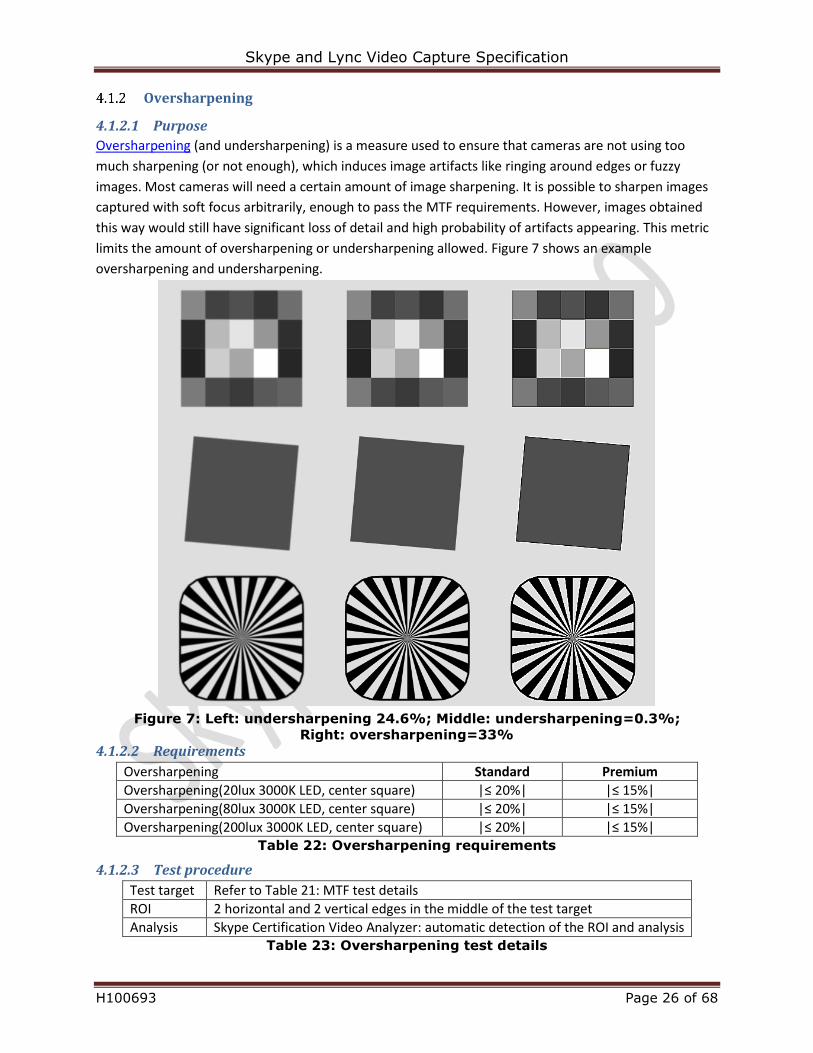
Oversharpening (and undersharpening) is a measure used to ensure that cameras are not using too
much sharpening (or not enough), which induces image artifacts like ringing around edges or fuzzy
images. Most cameras will need a certain amount of image sharpening. It is possible to sharpen images
captured with soft focus arbitrarily, enough to pass the MTF requirements. However, images obtained
this way would still have significant loss of detail and high probability of artifacts appearing. This metric
limits the amount of oversharpening or undersharpening allowed. Figure 7 shows an example
oversharpening and undersharpening.
Figure 7: Left: undersharpening 24.6%; Middle: undersharpening=0.3%;
Right: oversharpening=33%
4.1.2.2 Requirements
Oversharpening Standard Premium
Oversharpening(20lux 3000K LED, center square) |≤ 20%| |≤ 15%|
Oversharpening(80lux 3000K LED, center square) |≤ 20%| |≤ 15%|
Oversharpening(200lux 3000K LED, center square) |≤ 20%| |≤ 15%| Table 22: Oversharpening requirements
4.1.2.3 Test procedure
Test target Refer to Table 21: MTF test details
ROI 2 horizontal and 2 vertical edges in the middle of the test target
Analysis Skype Certification Video Analyzer: automatic detection of the ROI and analysis Table 23: Oversharpening test details
Skype and Lync Video Capture Specification
H100693 Page 27 of 68
Edge roughness
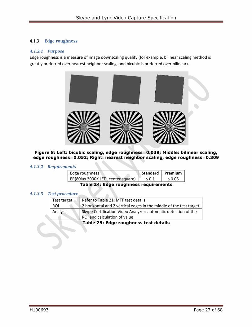
4.1.3.1 Purpose
Edge roughness is a measure of image downscaling quality (for example, bilinear scaling method is
greatly preferred over nearest neighbor scaling, and bicubic is preferred over bilinear).
Figure 8: Left: bicubic scaling, edge roughness=0.039; Middle: bilinear scaling,
edge roughness=0.052; Right: nearest neighbor scaling, edge roughness=0.309
4.1.3.2 Requirements
Edge roughness Standard Premium
ER(80lux 3000K LED, center square) ≤ 0.1 ≤ 0.05 Table 24: Edge roughness requirements
4.1.3.3 Test procedure
Test target Refer to Table 21: MTF test details
ROI 2 horizontal and 2 vertical edges in the middle of the test target
Analysis Skype Certification Video Analyzer: automatic detection of the ROI and calculation of value Table 25: Edge roughness test details
Skype and Lync Video Capture Specification
H100693 Page 28 of 68
Depth of field
4.1.4.1 Purpose
Defines the range where a camera with fixed focus, manual focus, or automatic focus should be able to
focus.
Related standard: ISO 12233-2000.
4.1.4.2 Requirements
Depth of field Standard Premium
MTF30 min distance (80lux 3000K LED, center square / all edges)
[0.3,0.8] [0.4,0.7]
MTF30 max distance (80lux 3000K LED, center square / all edges)
[0.3,0.8] [0.4,0.7]
Table 26: Depth of field requirements
4.1.4.3 Test procedure
Test target Default: SFR Plus (small) Alternate: SFR Plus (large) Use the SFRPlus (small) test chart, capture the image. Make sure that the full chart fills at least 75% of pixel area. If the camera FOV is very wide or test distance causes the chart to appear smaller than the above recommendation then use the alternate test chart instead.
ROI 2 horizontal and 2 vertical edges in the middle of the test target
Analysis Skype Certification Video Analyzer: automatic detection of the ROI and calculation of value
Table 27: Depth of field test details
Texture acutance
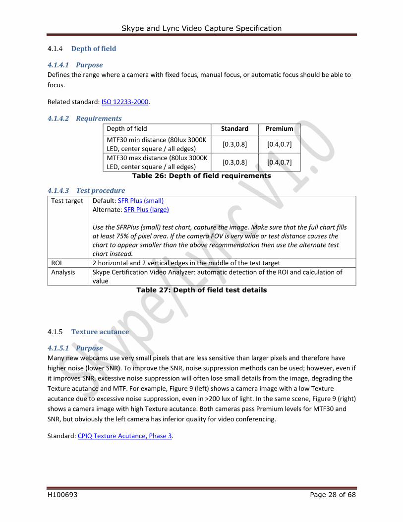
4.1.5.1 Purpose
Many new webcams use very small pixels that are less sensitive than larger pixels and therefore have
higher noise (lower SNR). To improve the SNR, noise suppression methods can be used; however, even if
it improves SNR, excessive noise suppression will often lose small details from the image, degrading the
Texture acutance and MTF. For example, Figure 9 (left) shows a camera image with a low Texture
acutance due to excessive noise suppression, even in >200 lux of light. In the same scene, Figure 9 (right)
shows a camera image with high Texture acutance. Both cameras pass Premium levels for MTF30 and
SNR, but obviously the left camera has inferior quality for video conferencing.
Standard: CPIQ Texture Acutance, Phase 3.
Skype and Lync Video Capture Specification
H100693 Page 29 of 68
Figure 9: Left: Cropped image from a 720p camera with low Texture acutance;
Right: cropped image from another 720p camera (different than the left one) with
high Texture acutance
4.1.5.2 Requirements
Texture acutance Standard Premium
Acutance (20lux 3000K LED) ≥ 0.70 ≥ 0.80
Acutance (80lux 3000K LED) ≥ 0.70 ≥ 0.83 Table 28: Texture acutance requirements
Resolutions to be tested for texture acutance are the following:
640x360
640x480
1280x720
1920x1080(if supported)
4.1.5.3 Test procedure
Test target Default: 8”x8” Spilled coins test chart Alternate: 12”x12” Spilled coins test chart Use the 8’’x8’’ test chart, capture the image Make sure that the chart active analysis area is at least 256 pixels high vertically. If the camera FOV is very wide or the test 1m test distance causes the chart to appear smaller than the above recommendation, then use the 12’’x12’’ test chart instead.
Analysis Skype Certification Video Analyzer: automatic detection of the ROI and calculation of value
Table 29: Texture acutance test details
Skype and Lync Video Capture Specification
H100693 Page 30 of 68
4.2 Noise
Image spatial SNR
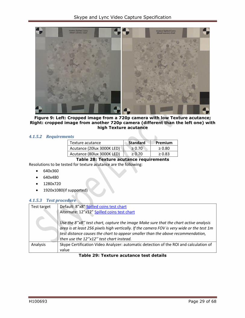
4.2.1.1 Purpose
Spatial noise is the measure of image noise in a single image. Spatial noise indicates a pixel level
variation of each pixel compared to neighboring pixels on single captured image. Figure 10 is an example
of a high and low noise image.
Figure 10: Left: SNR=29.2 dB; Right: SNR=44.2 dB
4.2.1.2 Requirement
Spatial SNR Standard Premium
SNR(20lux 3000K LED) ≥ 32 dB ≥ 35 dB
SNR(80lux 3000K LED) ≥ 35 dB ≥ 38 dB
SNR(20lux 6000K LED) ≥ 32 dB ≥ 35 dB
SNR(80lux 6000K LED) ≥ 35 dB ≥ 38 dB Table 30: Image spatial SNR requirements for resolutions upto and including 360p
Spatial SNR Standard Premium
SNR(20lux 3000K LED) ≥ 30 dB ≥ 33 dB
SNR(80lux 3000K LED) ≥ 33 dB ≥ 36 dB
SNR(20lux 6000K LED) ≥ 30 dB ≥ 33 dB
SNR(80lux 6000K LED) ≥ 33 dB ≥ 36 dB Table 31: Image spatial SNR requirements for resolutions higher than 360p
4.2.1.3 Test procedure
Test target ST-52 (LED brightness determined in Section 3.4.5)
ROI Patch number 7
Analysis Skype Certification Video Analyzer: automatic detection of the ROI and calculation of value
Table 32: Image spatial SNR test details
Skype and Lync Video Capture Specification
H100693 Page 31 of 68
Image temporal SNR
4.2.2.1 Purpose
Temporal noise is the measure of noise as difference of pixel values in consecutive frames. As opposed
to spatial noise that indicates a pixel level variation of each pixel within a single captured frame,
compared to neighboring pixels, the temporal noise measurement compares the pixel value difference
of the same pixel on two consecutive images. Temporal noise becomes visible to human eye when
looking at a live video image instead of a single snapshot.
4.2.2.1.1 Requirement
Temporal SNR Standard Premium
TSNR(20lux 3000K LED) ≥ 30 dB ≥ 33 dB
TSNR(80lux 3000K LED) ≥ 33 dB ≥ 36 dB
TSNR(20lux 6000K LED) ≥ 30 dB ≥ 33 dB
TSNR(80lux 6000K LED) ≥ 33 dB ≥ 36 dB Table 33: Image temporal SNR requirements
4.2.2.1.2 Test procedure
Test target ST-52
ROI Patch number 7
Analysis Skype Certification Video Analyzer: automatic detection of the ROI and calculation of value Select 2 captures in the Video Analyzer and run the test. The captures have to be unique frames with the same resolution and captured in minimal interval between them without moving the camera.
Table 34: Image temporal SNR test details
Skype and Lync Video Capture Specification
H100693 Page 32 of 68
4.3 Color quality
Gamma
4.3.1.1 Purpose
Windows monitors and projectors are standardized to have a gamma of 2.2 (via sRGB), so a camera
gamma of 0.45 ensures a linear response of the total capture-to-render system. Gamma >> 0.45 can give
images that have excessive contrast and look unnatural due to the non-linear color mapping.
Related standard: ISO 14524-1999.
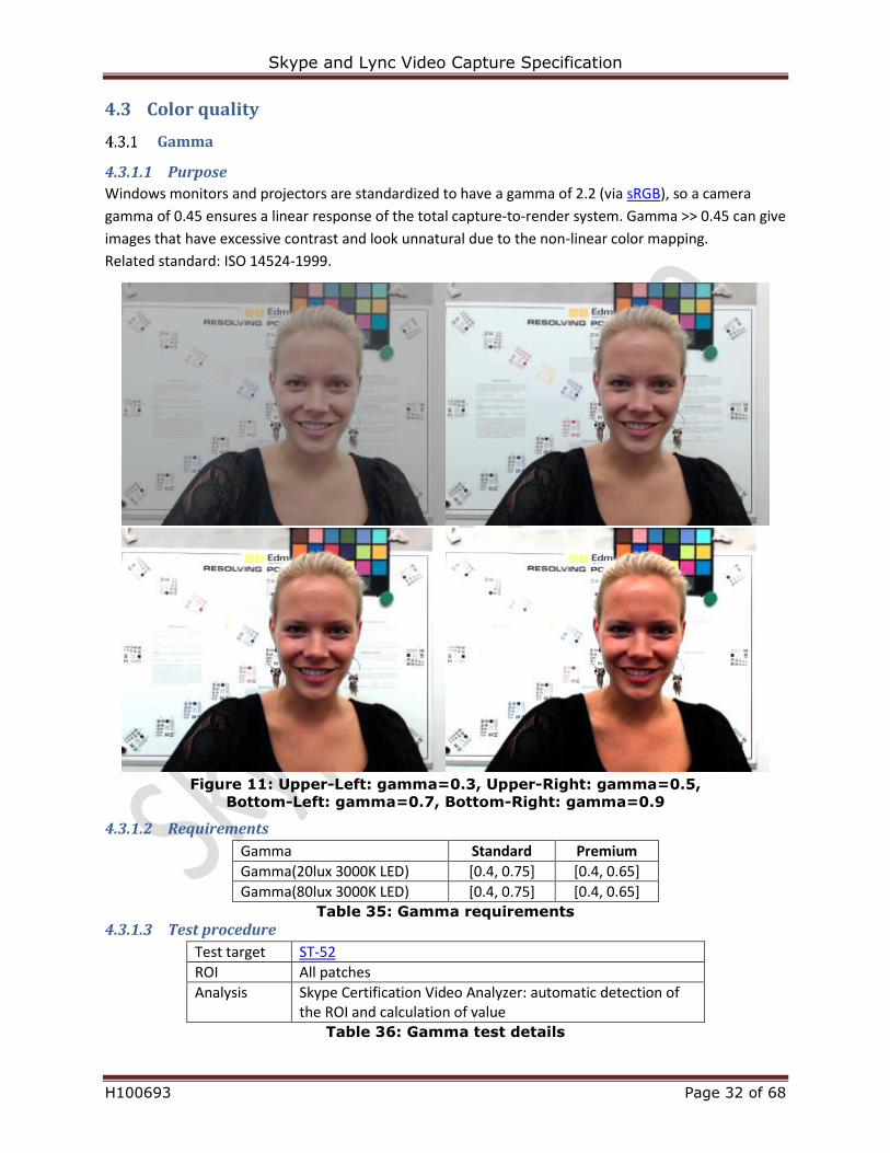
Figure 11: Upper-Left: gamma=0.3, Upper-Right: gamma=0.5,
Bottom-Left: gamma=0.7, Bottom-Right: gamma=0.9
4.3.1.2 Requirements
Gamma Standard Premium
Gamma(20lux 3000K LED) [0.4, 0.75] [0.4, 0.65]
Gamma(80lux 3000K LED) [0.4, 0.75] [0.4, 0.65] Table 35: Gamma requirements
4.3.1.3 Test procedure
Test target ST-52
ROI All patches
Analysis Skype Certification Video Analyzer: automatic detection of the ROI and calculation of value
Table 36: Gamma test details
Skype and Lync Video Capture Specification
H100693 Page 33 of 68
Image dynamic range
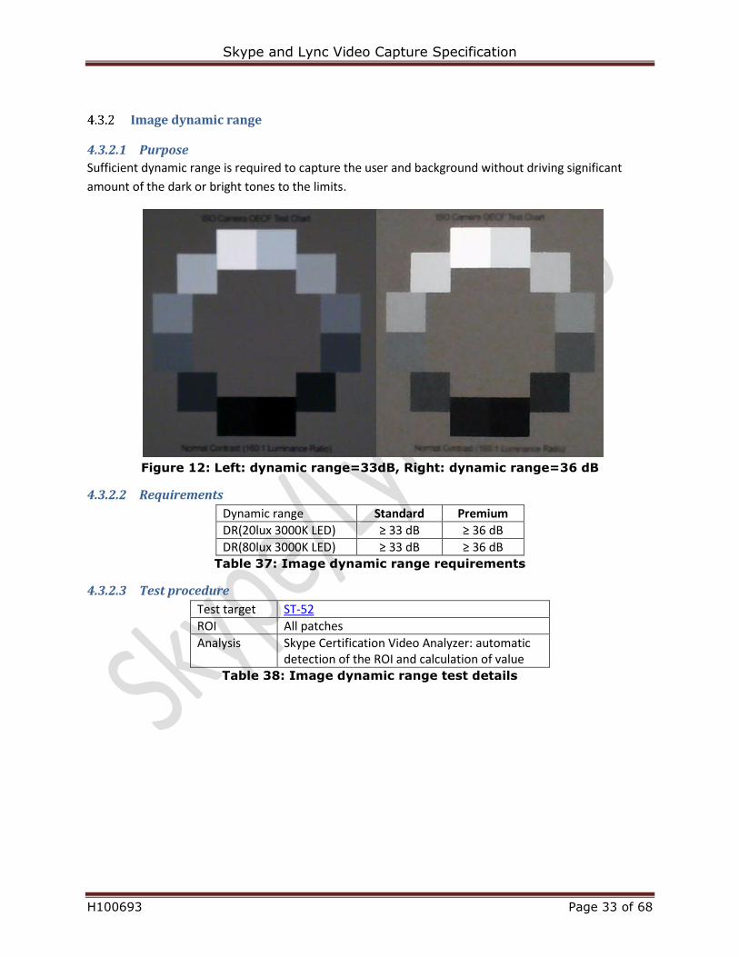
4.3.2.1 Purpose
Sufficient dynamic range is required to capture the user and background without driving significant
amount of the dark or bright tones to the limits.
Figure 12: Left: dynamic range=33dB, Right: dynamic range=36 dB
4.3.2.2 Requirements
Dynamic range Standard Premium
DR(20lux 3000K LED) ≥ 33 dB ≥ 36 dB
DR(80lux 3000K LED) ≥ 33 dB ≥ 36 dB Table 37: Image dynamic range requirements
4.3.2.3 Test procedure
Test target ST-52
ROI All patches
Analysis Skype Certification Video Analyzer: automatic detection of the ROI and calculation of value
Table 38: Image dynamic range test details
Skype and Lync Video Capture Specification
H100693 Page 34 of 68
Relative illumination
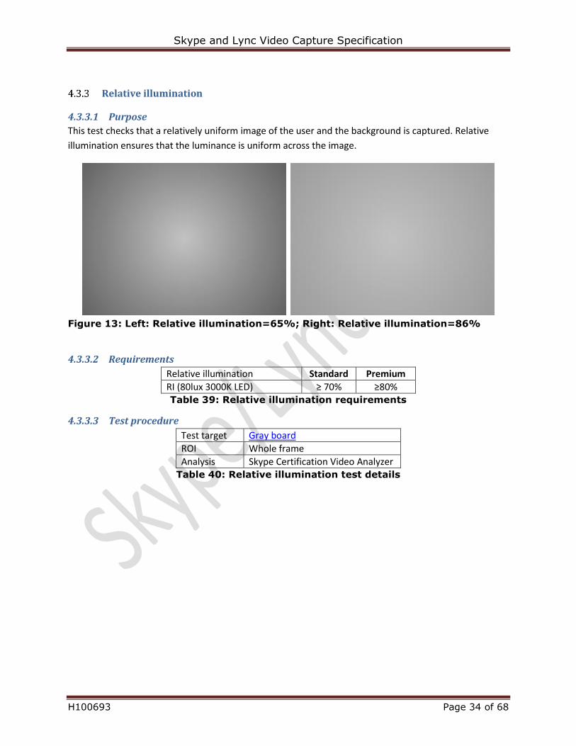
4.3.3.1 Purpose
This test checks that a relatively uniform image of the user and the background is captured. Relative
illumination ensures that the luminance is uniform across the image.
Figure 13: Left: Relative illumination=65%; Right: Relative illumination=86%
4.3.3.2 Requirements
Relative illumination Standard Premium
RI (80lux 3000K LED) ≥ 70% ≥80% Table 39: Relative illumination requirements
4.3.3.3 Test procedure
Test target Gray board
ROI Whole frame
Analysis Skype Certification Video Analyzer Table 40: Relative illumination test details
Skype and Lync Video Capture Specification
H100693 Page 35 of 68
Color uniformity
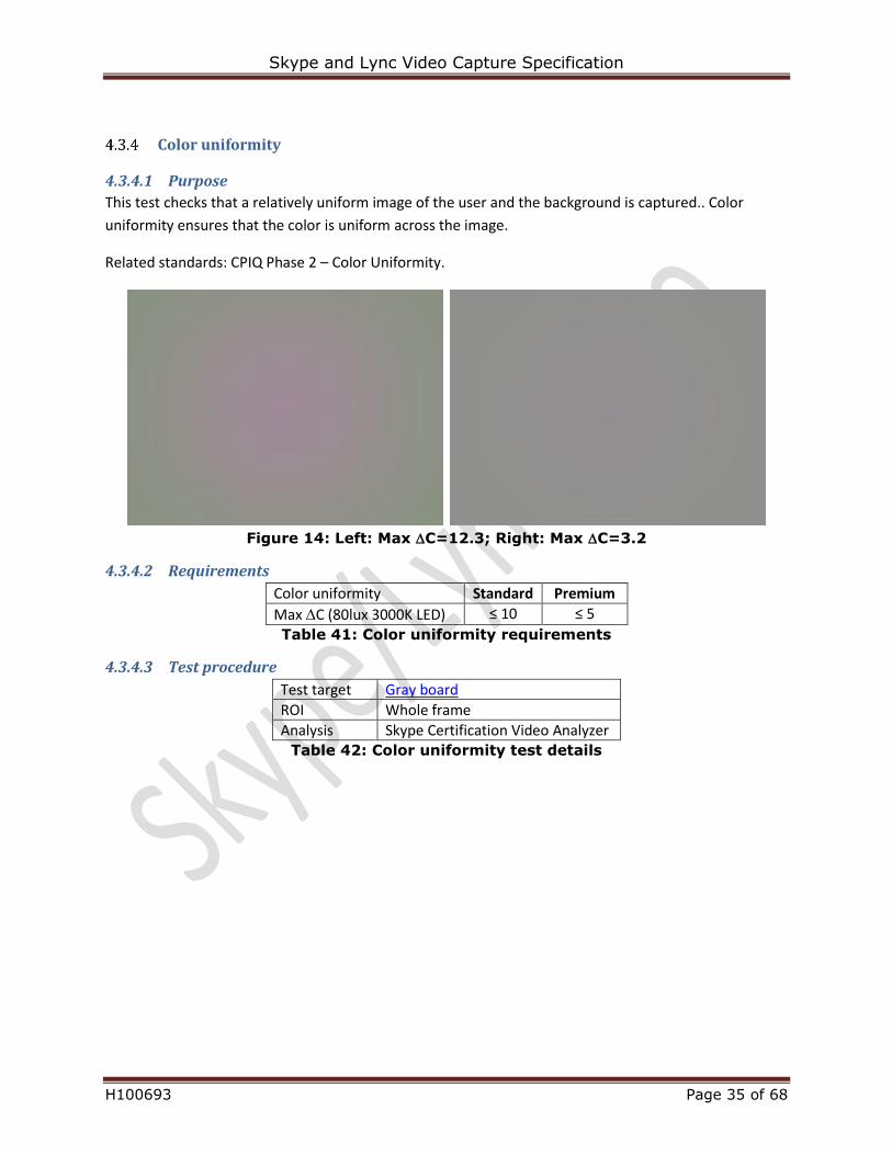
4.3.4.1 Purpose
This test checks that a relatively uniform image of the user and the background is captured.. Color
uniformity ensures that the color is uniform across the image.
Related standards: CPIQ Phase 2 – Color Uniformity.
Figure 14: Left: Max C=12.3; Right: Max C=3.2
4.3.4.2 Requirements
Color uniformity Standard Premium
Max C (80lux 3000K LED) ≤ 10 ≤ 5
Table 41: Color uniformity requirements
4.3.4.3 Test procedure
Test target Gray board
ROI Whole frame
Analysis Skype Certification Video Analyzer Table 42: Color uniformity test details

Skype and Lync Video Capture Specification
H100693 Page 36 of 68
Veiling glare
4.3.5.1 Purpose
Due to internal reflections, light sources targeted to a camera may cause light scattering to extensive
areas of its sensor. This stray light mostly affects the darker parts of a frame, in effect lowering the
dynamic range of the camera. For cameras without anti-reflective coating and/or without lens hoods,
even common overhead lighting can cause significant fidelity problems. The Veiling glare test measures
the amount of stray light, to avoid its impact on image quality and the loss of dynamic range and acuity.
Figure 15: Left: Notebook webcam image with typical room lighting; Right: same
camera with simple lens hood added, which improves the veiling glare from Basic
to Premium; good anti-reflective coatings can have the same improvement
4.3.5.2 Requirements
Veiling glare Standard Premium
Veiling glare (avg pixel value) ≤ 10 ≤ 5 Table 43: Veiling glare requirements
4.3.5.3 Test procedure
Adjust the veiling glare light for a reading of 80Lux at a horizontal surface at the camera
position, as described in Section 0
o Make sure to use exactly the same type of light bulb for the veiling glare light as for the
two auxiliary test target illumination lights.
o Verify that the veiling glare light does not increase the illuminance of the test target by
more than 5 Lux
Adjust the main auxiliary lights for 80Lux on test target
Capture an image of the uniform gray board with only the two main auxiliary lights turned on
Capture an image of the uniform gray board with both the two main auxiliary lights turned on
and the glare light also turned on
Skype and Lync Video Capture Specification
H100693 Page 37 of 68
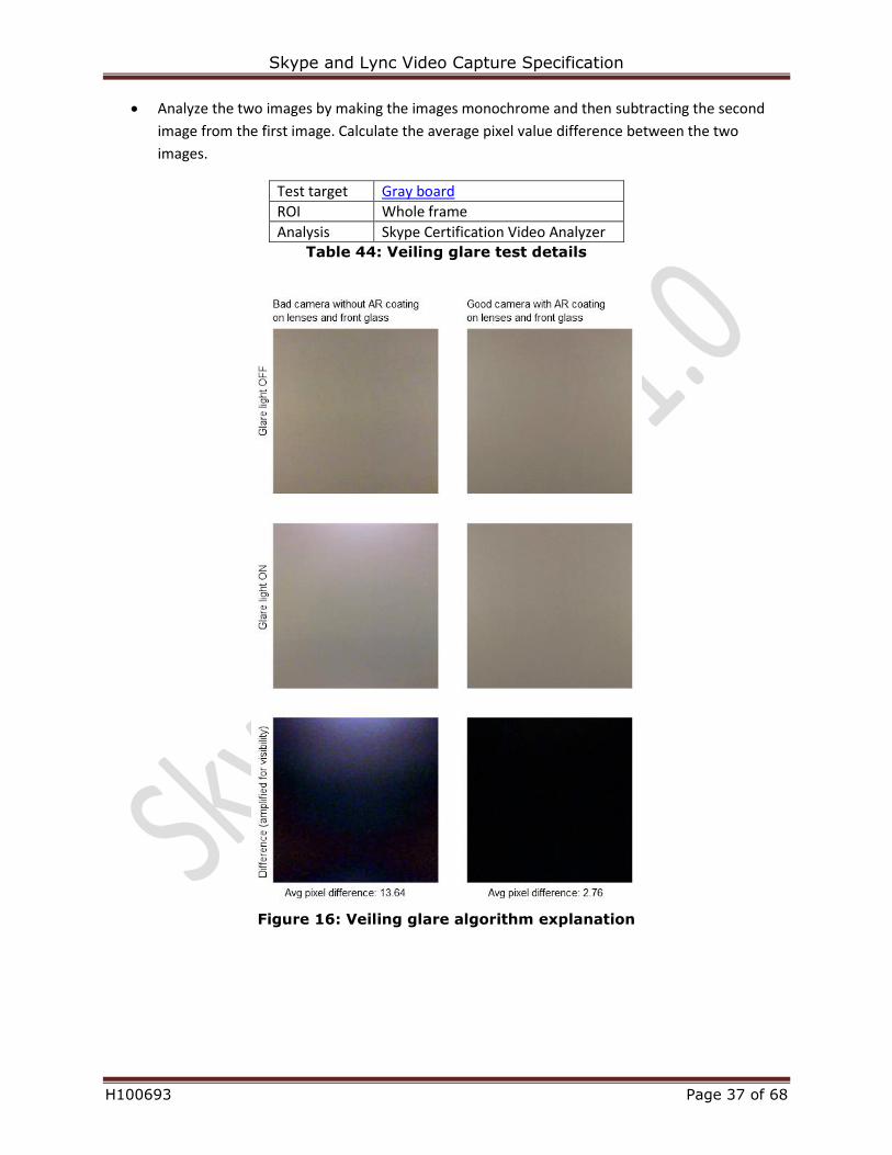
Analyze the two images by making the images monochrome and then subtracting the second
image from the first image. Calculate the average pixel value difference between the two
images.
Test target Gray board
ROI Whole frame
Analysis Skype Certification Video Analyzer Table 44: Veiling glare test details
Figure 16: Veiling glare algorithm explanation
Skype and Lync Video Capture Specification
H100693 Page 38 of 68
Color accuracy
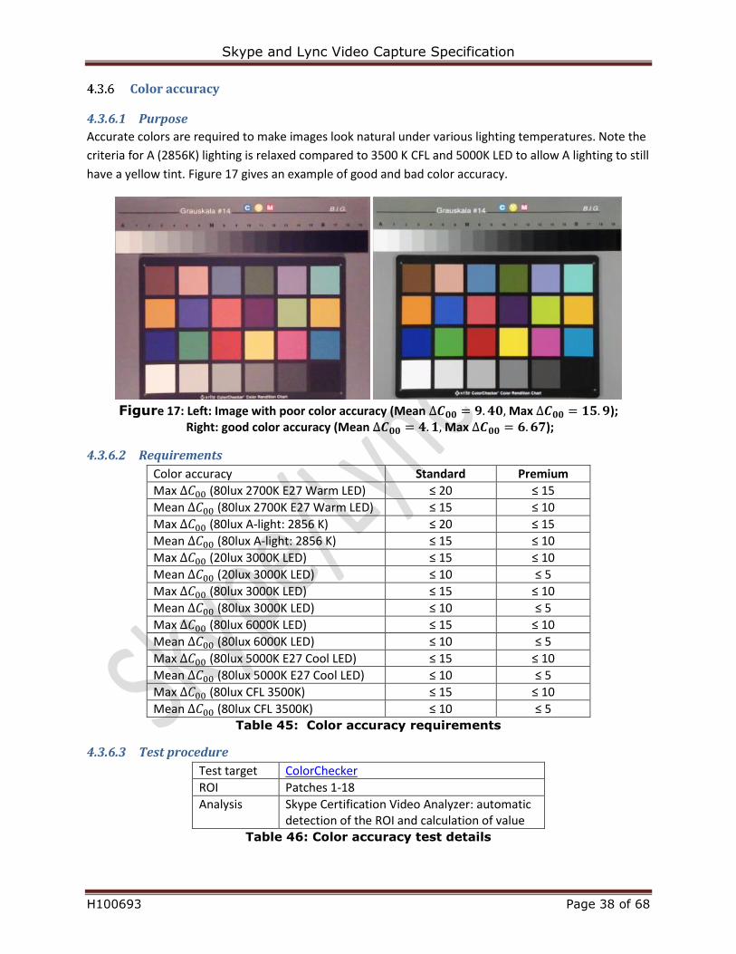
4.3.6.1 Purpose
Accurate colors are required to make images look natural under various lighting temperatures. Note the
criteria for A (2856K) lighting is relaxed compared to 3500 K CFL and 5000K LED to allow A lighting to still
have a yellow tint. Figure 17 gives an example of good and bad color accuracy.
Figure 17: Left: Image with poor color accuracy (Mean ∆𝑪𝟎𝟎 = 𝟗. 𝟒𝟎, Max ∆𝑪𝟎𝟎 = 𝟏𝟓. 𝟗);
Right: good color accuracy (Mean ∆𝑪𝟎𝟎 = 𝟒. 𝟏, Max ∆𝑪𝟎𝟎 = 𝟔. 𝟔𝟕);
4.3.6.2 Requirements
Color accuracy Standard Premium
Max ∆𝐶00 (80lux 2700K E27 Warm LED) ≤ 20 ≤ 15
Mean ∆𝐶00 (80lux 2700K E27 Warm LED) ≤ 15 ≤ 10
Max ∆𝐶00 (80lux A-light: 2856 K) ≤ 20 ≤ 15
Mean ∆𝐶00 (80lux A-light: 2856 K) ≤ 15 ≤ 10
Max ∆𝐶00 (20lux 3000K LED) ≤ 15 ≤ 10
Mean ∆𝐶00 (20lux 3000K LED) ≤ 10 ≤ 5
Max ∆𝐶00 (80lux 3000K LED) ≤ 15 ≤ 10
Mean ∆𝐶00 (80lux 3000K LED) ≤ 10 ≤ 5
Max ∆𝐶00 (80lux 6000K LED) ≤ 15 ≤ 10
Mean ∆𝐶00 (80lux 6000K LED) ≤ 10 ≤ 5
Max ∆𝐶00 (80lux 5000K E27 Cool LED) ≤ 15 ≤ 10
Mean ∆𝐶00 (80lux 5000K E27 Cool LED) ≤ 10 ≤ 5
Max ∆𝐶00 (80lux CFL 3500K) ≤ 15 ≤ 10
Mean ∆𝐶00 (80lux CFL 3500K) ≤ 10 ≤ 5 Table 45: Color accuracy requirements
4.3.6.3 Test procedure
Test target ColorChecker
ROI Patches 1-18
Analysis Skype Certification Video Analyzer: automatic detection of the ROI and calculation of value
Table 46: Color accuracy test details
Skype and Lync Video Capture Specification
H100693 Page 39 of 68
Color saturation
4.3.7.1 Purpose
Accurate color saturation are required to make images look natural under various lighting temperatures.
4.3.7.2 Requirements
Saturation Standard Premium
Sat (80lux 2700K E27 Warm LED) [75%, 130%] [85%, 120%]
Sat (80lux A-light: 2856 K) [90%, 140%] [100%, 130%]
Sat (20lux 3000K LED) [75%, 130%] [85%, 120%]
Sat (80lux 3000K LED) [75%, 130%] [85%, 120%]
Sat (80lux 6000K LED) [75%, 130%] [85%, 120%]
Sat (80lux 5000K E27 Cool LED) [75%, 130%] [85%, 120%]
Sat (80lux CFL 3500K) [75%, 130%] [85%, 120%] Table 47: Color saturation requirements
4.3.7.3 Test procedure
Test target ColorChecker
ROI Patches 1-18
Analysis Skype Certification Video Analyzer: automatic detection of the ROI and calculation of value
Table 48: Color saturation test details
Exposure accuracy
4.3.8.1 Purpose
Automatic exposure is needed to ensure the image has sufficient contrast and isn't saturated or under-
saturated in typical light conditions.
4.3.8.2 Requirements
Mean value of Y channel on patch 22 on ColorChecker
Standard Premium
Y(20lux 3000K LED) [88, 168] [108, 148]
Y(80lux 3000K LED) [88, 168] [108, 148]
Y(200lux 3000K LED) [88, 168] [108, 148]
Y(1000lux 5000K LED) [88, 168] [98, 158] Table 49: Image exposure accuracy requirements
4.3.8.3 Test procedure
Test target ColorChecker
ROI Patch 22
Analysis Skype Certification Video Analyzer: automatic detection of the ROI and calculation of value
Table 50: Image exposure accuracy test details
Skype and Lync Video Capture Specification
H100693 Page 40 of 68
White balance error
4.3.9.1 Purpose
Accurate color representation is required to make images look natural under various types of lighting
with different color temperatures. In addition to color accuracy also gray world should keep neutral gray
tone instead of pink or magenta toning for example.
4.3.9.2 Requirements
White balance error Standard Premium
WB error P.21 (80lux 2700K E27 Warm LED) N/A ∆𝐶00 ≤ 10
WB error P.21 (80lux A-light: 2856 K) N/A ∆𝐶00 ≤ 10
WB error P.21 (20lux 3000K LED) N/A ∆𝐶00 ≤ 10
WB error P.21 (80lux 3000K LED) N/A ∆𝐶00 ≤ 5
WB error P.21 (80lux 6000K LED) N/A ∆𝐶00 ≤ 5
WB error P.21 (80lux 5000K E27 Cool LED) N/A ∆𝐶00 ≤ 5
WB error P.21 (80lux CFL 3500K) N/A ∆𝐶00 ≤ 5 Table 51: White balance error requirements
4.3.9.3 Test procedure
Test target ColorChecker
ROI Patch 21
Analysis Skype Certification Video Analyzer: automatic detection of the ROI and calculation of value
Table 52: White balance error test details
4.4 Geometry
Field of view
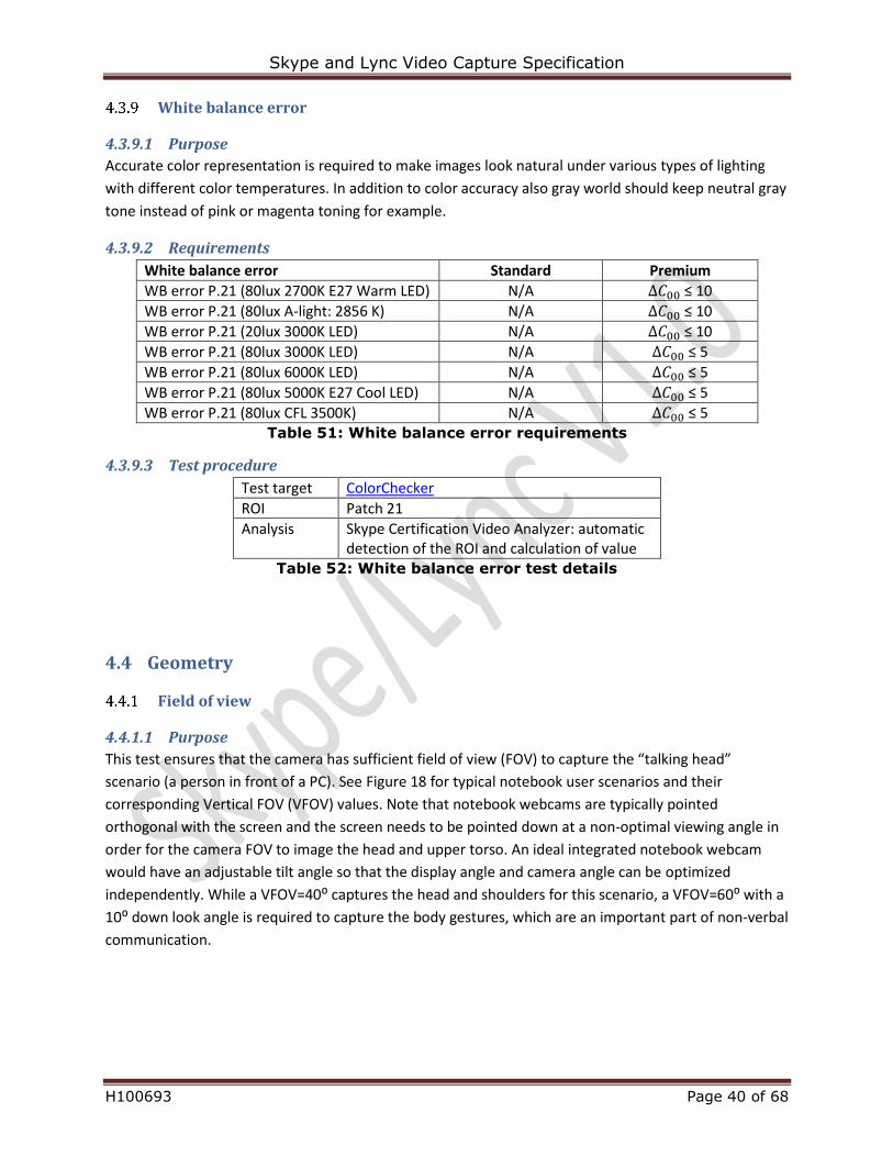
4.4.1.1 Purpose
This test ensures that the camera has sufficient field of view (FOV) to capture the “talking head”
scenario (a person in front of a PC). See Figure 18 for typical notebook user scenarios and their
corresponding Vertical FOV (VFOV) values. Note that notebook webcams are typically pointed
orthogonal with the screen and the screen needs to be pointed down at a non-optimal viewing angle in
order for the camera FOV to image the head and upper torso. An ideal integrated notebook webcam
would have an adjustable tilt angle so that the display angle and camera angle can be optimized
independently. While a VFOV=40⁰ captures the head and shoulders for this scenario, a VFOV=60⁰ with a
10⁰ down look angle is required to capture the body gestures, which are an important part of non-verbal
communication.
Skype and Lync Video Capture Specification
H100693 Page 41 of 68
60°40°
90°
Figure 18: Vertical FOV for a notebook conferencing scenario
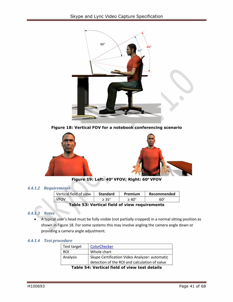
Figure 19: Left: 40⁰ VFOV; Right: 60⁰ VFOV
4.4.1.2 Requirements
Vertical field of view Standard Premium Recommended
VFOV ≥ 35 ≥ 40 60 Table 53: Vertical field of view requirements
4.4.1.3 Notes
A typical user’s head must be fully visible (not partially cropped) in a normal sitting position as
shown in Figure 18. For some systems this may involve angling the camera angle down or
providing a camera angle adjustment.
4.4.1.4 Test procedure
Test target ColorChecker
ROI Whole chart
Analysis Skype Certification Video Analyzer: automatic detection of the ROI and calculation of value
Table 54: Vertical field of view test details
Skype and Lync Video Capture Specification
H100693 Page 42 of 68
Field of view consistency
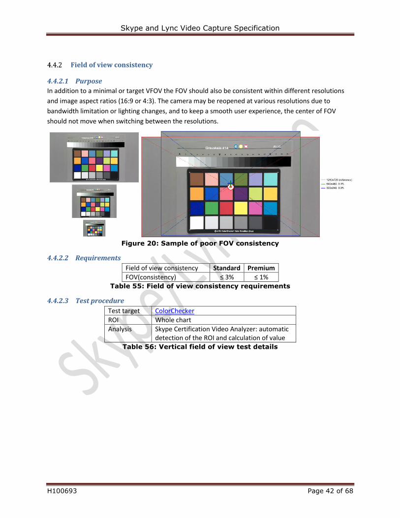
4.4.2.1 Purpose
In addition to a minimal or target VFOV the FOV should also be consistent within different resolutions
and image aspect ratios (16:9 or 4:3). The camera may be reopened at various resolutions due to
bandwidth limitation or lighting changes, and to keep a smooth user experience, the center of FOV
should not move when switching between the resolutions.
Figure 20: Sample of poor FOV consistency
4.4.2.2 Requirements
Field of view consistency Standard Premium
FOV(consistency) ≤ 3% ≤ 1% Table 55: Field of view consistency requirements
4.4.2.3 Test procedure
Test target ColorChecker
ROI Whole chart
Analysis Skype Certification Video Analyzer: automatic detection of the ROI and calculation of value
Table 56: Vertical field of view test details
Skype and Lync Video Capture Specification
H100693 Page 43 of 68
Geometric distortion
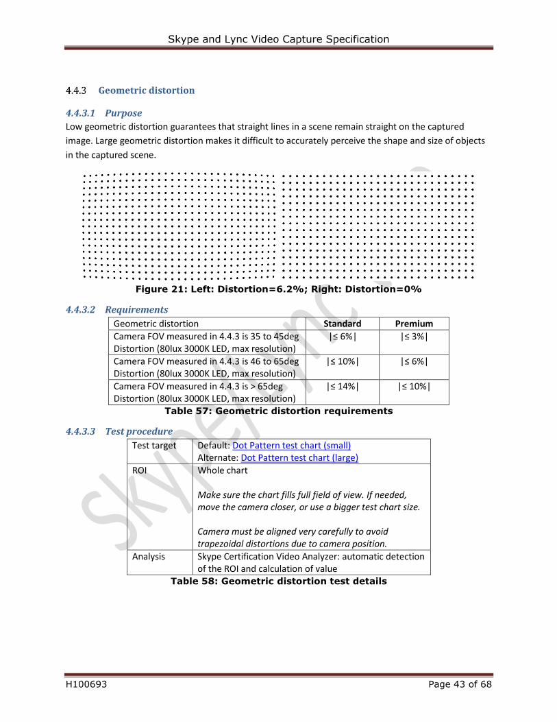
4.4.3.1 Purpose
Low geometric distortion guarantees that straight lines in a scene remain straight on the captured
image. Large geometric distortion makes it difficult to accurately perceive the shape and size of objects
in the captured scene.
Figure 21: Left: Distortion=6.2%; Right: Distortion=0%
4.4.3.2 Requirements
Geometric distortion Standard Premium
Camera FOV measured in 4.4.3 is 35 to 45deg Distortion (80lux 3000K LED, max resolution)
|≤ 6%| |≤ 3%|
Camera FOV measured in 4.4.3 is 46 to 65deg Distortion (80lux 3000K LED, max resolution)
|≤ 10%| |≤ 6%|
Camera FOV measured in 4.4.3 is > 65deg Distortion (80lux 3000K LED, max resolution)
|≤ 14%| |≤ 10%|
Table 57: Geometric distortion requirements
4.4.3.3 Test procedure
Test target Default: Dot Pattern test chart (small) Alternate: Dot Pattern test chart (large)
ROI Whole chart Make sure the chart fills full field of view. If needed, move the camera closer, or use a bigger test chart size. Camera must be aligned very carefully to avoid trapezoidal distortions due to camera position.
Analysis Skype Certification Video Analyzer: automatic detection of the ROI and calculation of value
Table 58: Geometric distortion test details
Skype and Lync Video Capture Specification
H100693 Page 44 of 68
4.5 Timing
System latency
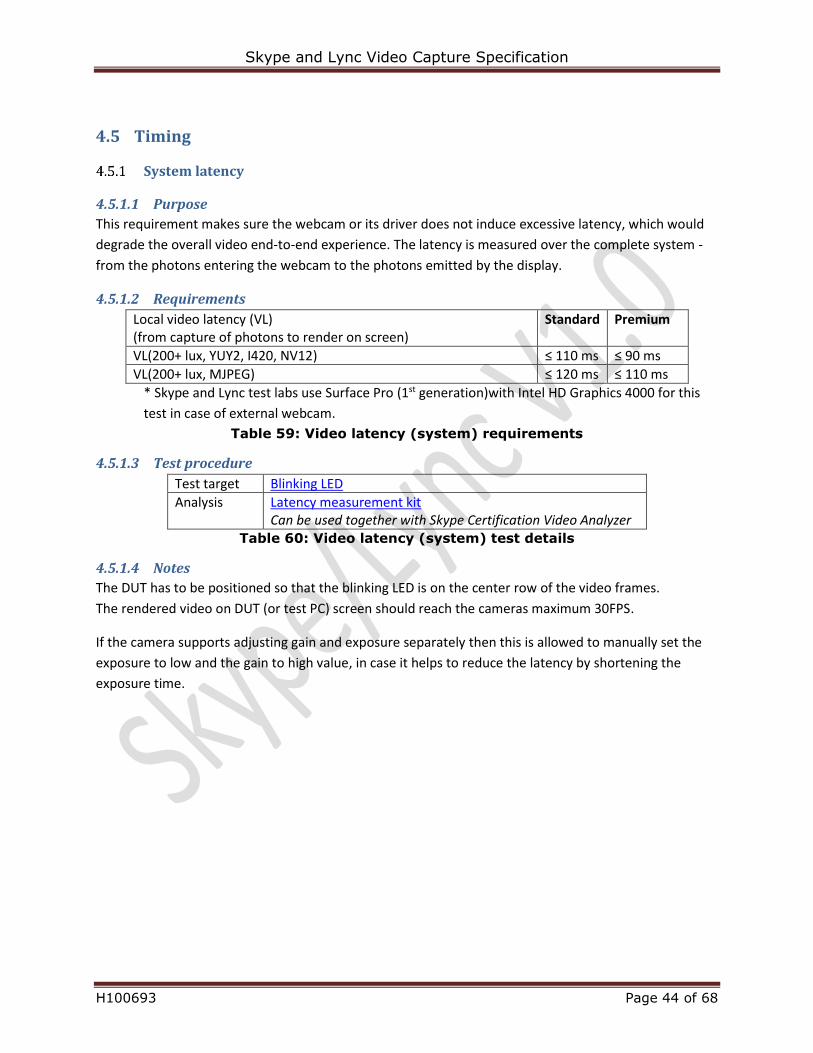
4.5.1.1 Purpose
This requirement makes sure the webcam or its driver does not induce excessive latency, which would
degrade the overall video end-to-end experience. The latency is measured over the complete system -
from the photons entering the webcam to the photons emitted by the display.
4.5.1.2 Requirements
Local video latency (VL) (from capture of photons to render on screen)
Standard Premium
VL(200+ lux, YUY2, I420, NV12) ≤ 110 ms ≤ 90 ms
VL(200+ lux, MJPEG) ≤ 120 ms ≤ 110 ms
* Skype and Lync test labs use Surface Pro (1st generation)with Intel HD Graphics 4000 for this
test in case of external webcam.
Table 59: Video latency (system) requirements
4.5.1.3 Test procedure
Test target Blinking LED
Analysis Latency measurement kit Can be used together with Skype Certification Video Analyzer
Table 60: Video latency (system) test details
4.5.1.4 Notes
The DUT has to be positioned so that the blinking LED is on the center row of the video frames.
The rendered video on DUT (or test PC) screen should reach the cameras maximum 30FPS.
If the camera supports adjusting gain and exposure separately then this is allowed to manually set the
exposure to low and the gain to high value, in case it helps to reduce the latency by shortening the
exposure time.
Skype and Lync Video Capture Specification
H100693 Page 45 of 68
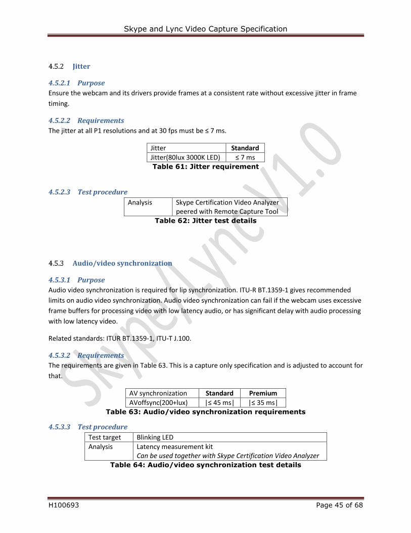
Jitter
4.5.2.1 Purpose
Ensure the webcam and its drivers provide frames at a consistent rate without excessive jitter in frame
timing.
4.5.2.2 Requirements
The jitter at all P1 resolutions and at 30 fps must be ≤ 7 ms.
Jitter Standard
Jitter(80lux 3000K LED) ≤ 7 ms Table 61: Jitter requirement
4.5.2.3 Test procedure
Analysis Skype Certification Video Analyzer peered with Remote Capture Tool
Table 62: Jitter test details
Audio/video synchronization
4.5.3.1 Purpose
Audio video synchronization is required for lip synchronization. ITU-R BT.1359-1 gives recommended
limits on audio video synchronization. Audio video synchronization can fail if the webcam uses excessive
frame buffers for processing video with low latency audio, or has significant delay with audio processing
with low latency video.
Related standards: ITUR BT.1359-1, ITU-T J.100.
4.5.3.2 Requirements
The requirements are given in Table 63. This is a capture only specification and is adjusted to account for
that.
AV synchronization Standard Premium
AVoffsync(200+lux) |≤ 45 ms| |≤ 35 ms| Table 63: Audio/video synchronization requirements
4.5.3.3 Test procedure
Test target Blinking LED
Analysis Latency measurement kit Can be used together with Skype Certification Video Analyzer
Table 64: Audio/video synchronization test details
Skype and Lync Video Capture Specification
H100693 Page 46 of 68
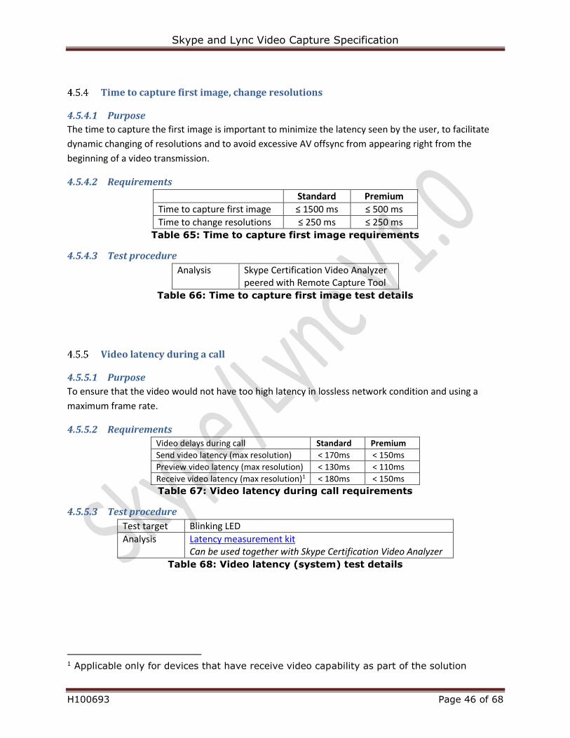
Time to capture first image, change resolutions
4.5.4.1 Purpose
The time to capture the first image is important to minimize the latency seen by the user, to facilitate
dynamic changing of resolutions and to avoid excessive AV offsync from appearing right from the
beginning of a video transmission.
4.5.4.2 Requirements
Standard Premium
Time to capture first image ≤ 1500 ms ≤ 500 ms
Time to change resolutions ≤ 250 ms ≤ 250 ms Table 65: Time to capture first image requirements
4.5.4.3 Test procedure
Analysis Skype Certification Video Analyzer peered with Remote Capture Tool
Table 66: Time to capture first image test details
Video latency during a call
4.5.5.1 Purpose
To ensure that the video would not have too high latency in lossless network condition and using a
maximum frame rate.
4.5.5.2 Requirements
Video delays during call Standard Premium
Send video latency (max resolution) < 170ms < 150ms
Preview video latency (max resolution) < 130ms < 110ms
Receive video latency (max resolution)1 < 180ms < 150ms
Table 67: Video latency during call requirements
4.5.5.3 Test procedure
Test target Blinking LED
Analysis Latency measurement kit Can be used together with Skype Certification Video Analyzer
Table 68: Video latency (system) test details
1 Applicable only for devices that have receive video capability as part of the solution
Skype and Lync Video Capture Specification
H100693 Page 47 of 68
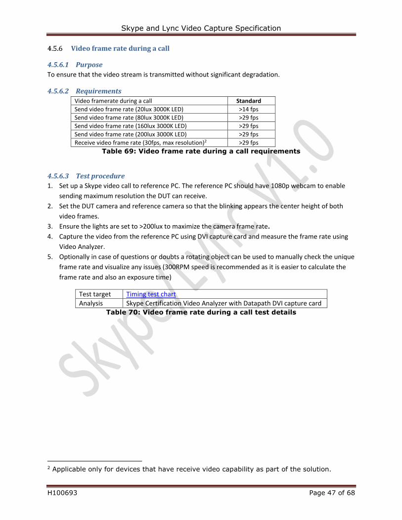
Video frame rate during a call
4.5.6.1 Purpose
To ensure that the video stream is transmitted without significant degradation.
4.5.6.2 Requirements
Video framerate during a call Standard
Send video frame rate (20lux 3000K LED) >14 fps
Send video frame rate (80lux 3000K LED) >29 fps
Send video frame rate (160lux 3000K LED) >29 fps
Send video frame rate (200lux 3000K LED) >29 fps
Receive video frame rate (30fps, max resolution)2 >29 fps
Table 69: Video frame rate during a call requirements
4.5.6.3 Test procedure
1. Set up a Skype video call to reference PC. The reference PC should have 1080p webcam to enable
sending maximum resolution the DUT can receive.
2. Set the DUT camera and reference camera so that the blinking appears the center height of both
video frames.
3. Ensure the lights are set to >200lux to maximize the camera frame rate.
4. Capture the video from the reference PC using DVI capture card and measure the frame rate using
Video Analyzer.
5. Optionally in case of questions or doubts a rotating object can be used to manually check the unique
frame rate and visualize any issues (300RPM speed is recommended as it is easier to calculate the
frame rate and also an exposure time)
Test target Timing test chart
Analysis Skype Certification Video Analyzer with Datapath DVI capture card Table 70: Video frame rate during a call test details
2 Applicable only for devices that have receive video capability as part of the solution.
Skype and Lync Video Capture Specification
H100693 Page 48 of 68
5 Video test setup
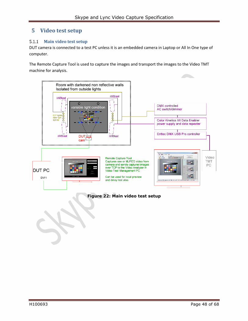
Main video test setup
DUT camera is connected to a test PC unless it is an embedded camera in Laptop or All In One type of
computer.
The Remote Capture Tool is used to capture the images and transport the images to the Video TMT
machine for analysis.
Figure 22: Main video test setup
Skype and Lync Video Capture Specification
H100693 Page 49 of 68
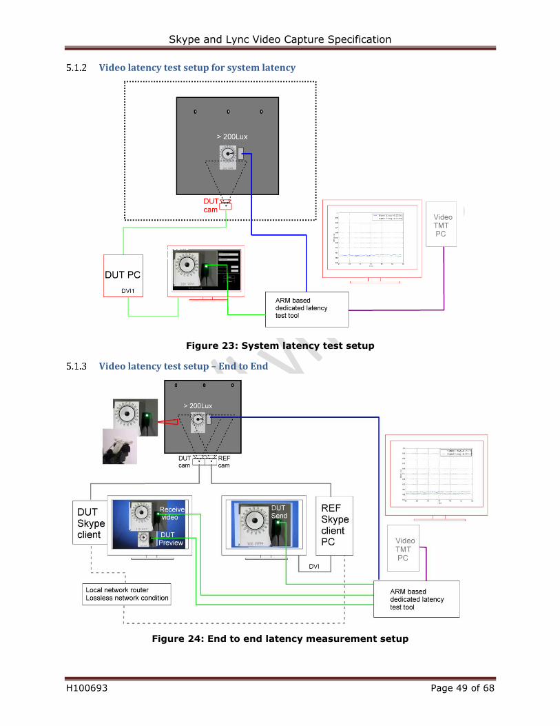
Video latency test setup for system latency
Figure 23: System latency test setup
Video latency test setup – End to End
Figure 24: End to end latency measurement setup
Skype and Lync Video Capture Specification
H100693 Page 50 of 68
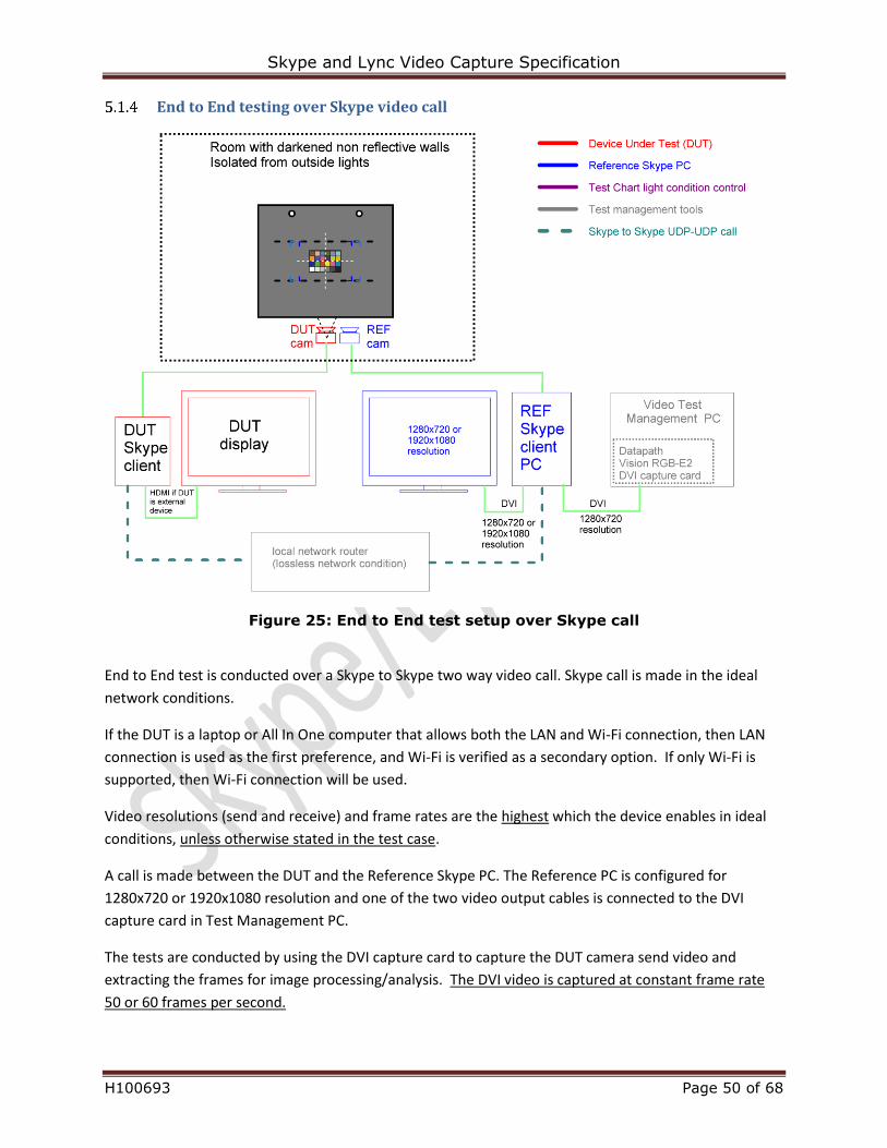
End to End testing over Skype video call
Figure 25: End to End test setup over Skype call
End to End test is conducted over a Skype to Skype two way video call. Skype call is made in the ideal
network conditions.
If the DUT is a laptop or All In One computer that allows both the LAN and Wi-Fi connection, then LAN
connection is used as the first preference, and Wi-Fi is verified as a secondary option. If only Wi-Fi is
supported, then Wi-Fi connection will be used.
Video resolutions (send and receive) and frame rates are the highest which the device enables in ideal
conditions, unless otherwise stated in the test case.
A call is made between the DUT and the Reference Skype PC. The Reference PC is configured for
1280x720 or 1920x1080 resolution and one of the two video output cables is connected to the DVI
capture card in Test Management PC.
The tests are conducted by using the DVI capture card to capture the DUT camera send video and
extracting the frames for image processing/analysis. The DVI video is captured at constant frame rate
50 or 60 frames per second.
Skype and Lync Video Capture Specification
H100693 Page 51 of 68
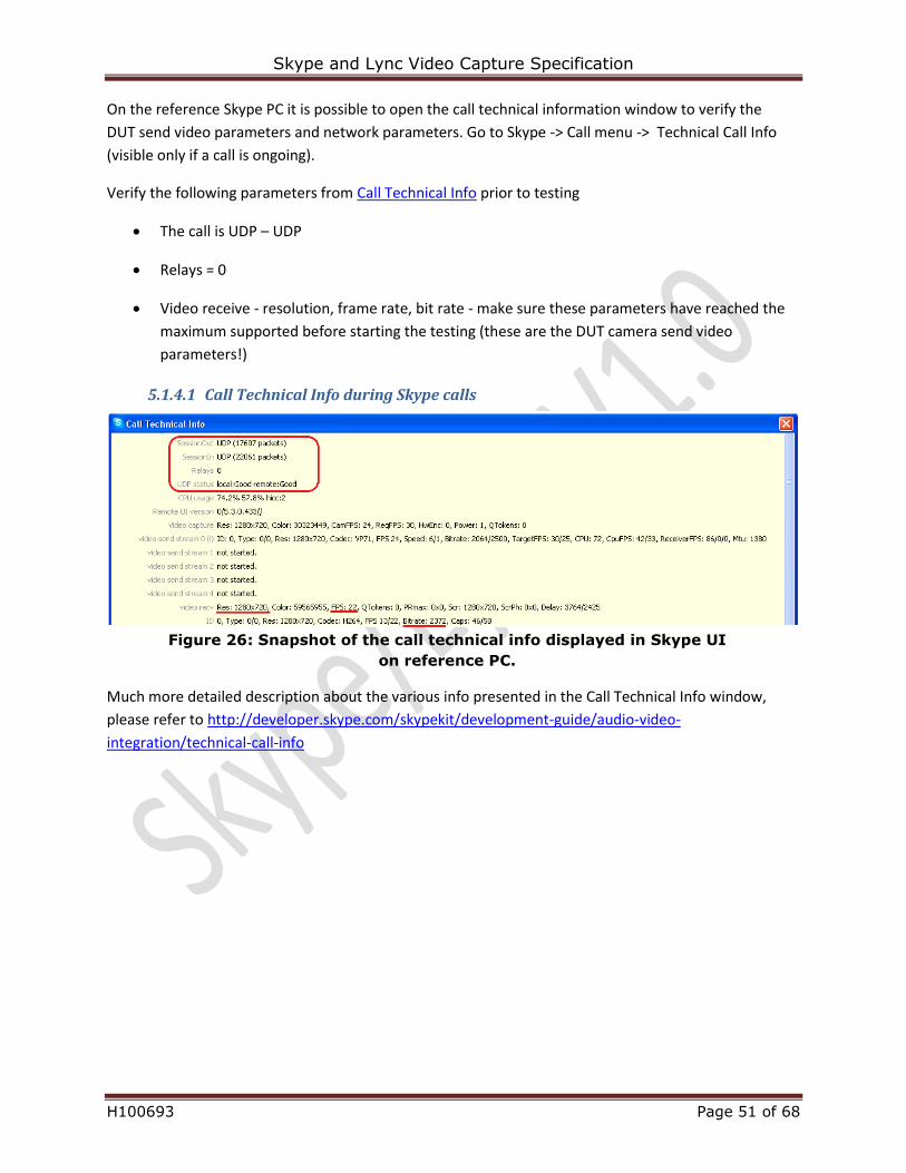
On the reference Skype PC it is possible to open the call technical information window to verify the
DUT send video parameters and network parameters. Go to Skype -> Call menu -> Technical Call Info
(visible only if a call is ongoing).
Verify the following parameters from Call Technical Info prior to testing
The call is UDP – UDP
Relays = 0
Video receive - resolution, frame rate, bit rate - make sure these parameters have reached the
maximum supported before starting the testing (these are the DUT camera send video
parameters!)
5.1.4.1 Call Technical Info during Skype calls
Figure 26: Snapshot of the call technical info displayed in Skype UI
on reference PC.
Much more detailed description about the various info presented in the Call Technical Info window,
please refer to http://developer.skype.com/skypekit/development-guide/audio-video-
integration/technical-call-info
Skype and Lync Video Capture Specification
H100693 Page 52 of 68
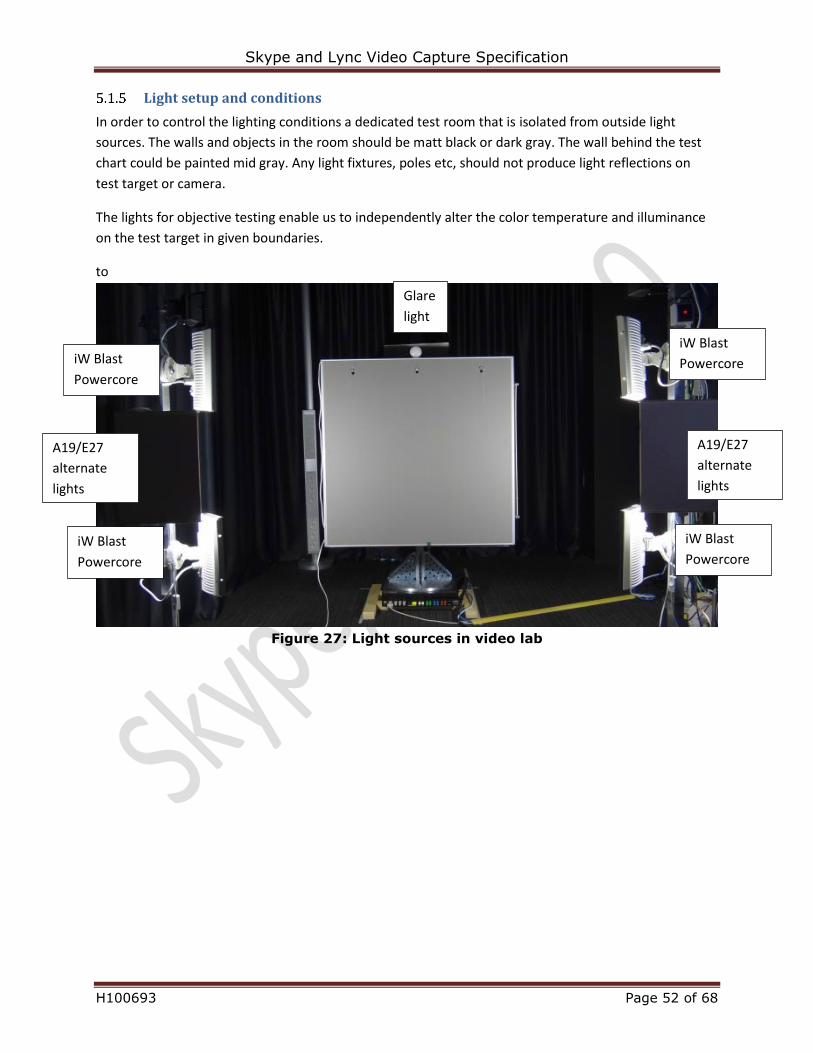
Light setup and conditions
In order to control the lighting conditions a dedicated test room that is isolated from outside light
sources. The walls and objects in the room should be matt black or dark gray. The wall behind the test
chart could be painted mid gray. Any light fixtures, poles etc, should not produce light reflections on
test target or camera.
The lights for objective testing enable us to independently alter the color temperature and illuminance
on the test target in given boundaries.
to
Figure 27: Light sources in video lab
A19/E27
alternate
lights
A19/E27
alternate
lights
iW Blast
Powercore
iW Blast
Powercore
iW Blast
Powercore
iW Blast
Powercore
Glare
light
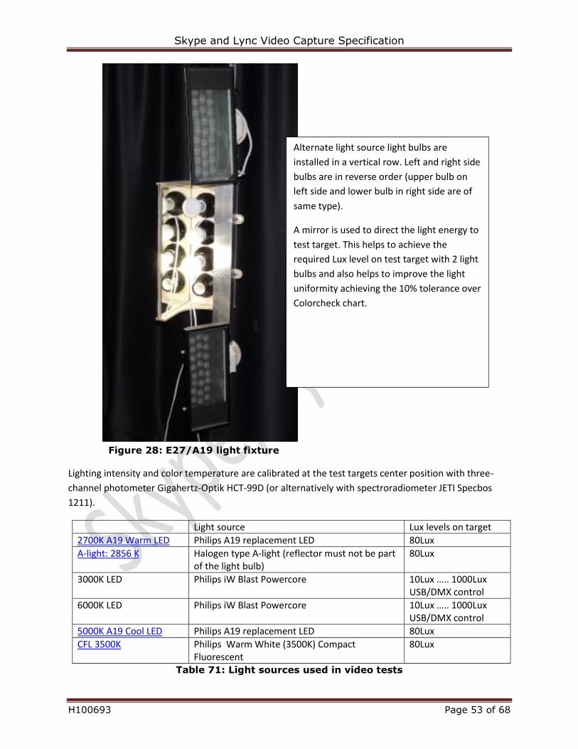
Skype and Lync Video Capture Specification
H100693 Page 53 of 68
Figure 28: E27/A19 light fixture
Lighting intensity and color temperature are calibrated at the test targets center position with three-
channel photometer Gigahertz-Optik HCT-99D (or alternatively with spectroradiometer JETI Specbos
1211).
Light source Lux levels on target
2700K A19 Warm LED Philips A19 replacement LED 80Lux
A-light: 2856 K Halogen type A-light (reflector must not be part of the light bulb)
80Lux
3000K LED Philips iW Blast Powercore 10Lux ….. 1000Lux USB/DMX control
6000K LED Philips iW Blast Powercore 10Lux ….. 1000Lux USB/DMX control
5000K A19 Cool LED Philips A19 replacement LED 80Lux
CFL 3500K Philips Warm White (3500K) Compact Fluorescent
80Lux
Table 71: Light sources used in video tests
Alternate light source light bulbs are
installed in a vertical row. Left and right side
bulbs are in reverse order (upper bulb on
left side and lower bulb in right side are of
same type).
A mirror is used to direct the light energy to
test target. This helps to achieve the
required Lux level on test target with 2 light
bulbs and also helps to improve the light
uniformity achieving the 10% tolerance over
Colorcheck chart.
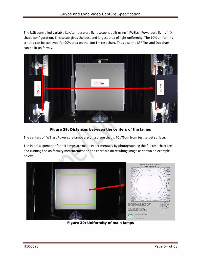
Skype and Lync Video Capture Specification
H100693 Page 54 of 68
The USB controlled variable Lux/temperature light setup is built using 4 iWBlast Powercore lights in X
shape configuration. This setup gives the best and largest area of light uniformity. The 10% uniformity
criteria can be achieved for 90% area on the 1mx1m test chart. Thus also the SFRPlus and Dot chart
can be lit uniformly.
Figure 29: Distances between the centers of the lamps
The centers of iWBlast Powercore lamps are on a plane that is 70..75cm from test target surface.
The initial alignment of the 4 lamps are made experimentally by photographing the full test chart area
and running the uniformity measurement on the chart are on resulting image as shown on example
below.
Figure 30: Uniformity of main lamps
170cm
75
cm
75
cm
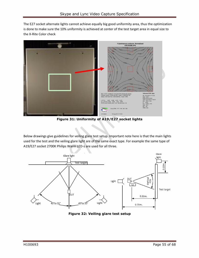
Skype and Lync Video Capture Specification
H100693 Page 55 of 68
The E27 socket alternate lights cannot achieve equally big good uniformity area, thus the optimization
is done to make sure the 10% uniformity is achieved at center of the test target area in equal size to
the X-Rite Color check
Figure 31: Uniformity of A19/E27 socket lights
Below drawings give guidelines for veiling glare test setup. Important note here is that the main lights
used for the test and the veiling glare light are of the same exact type. For example the same type of
A19/E27 socket 2700K Philips Warm LED-s are used for all three.
Figure 32: Veiling glare test setup
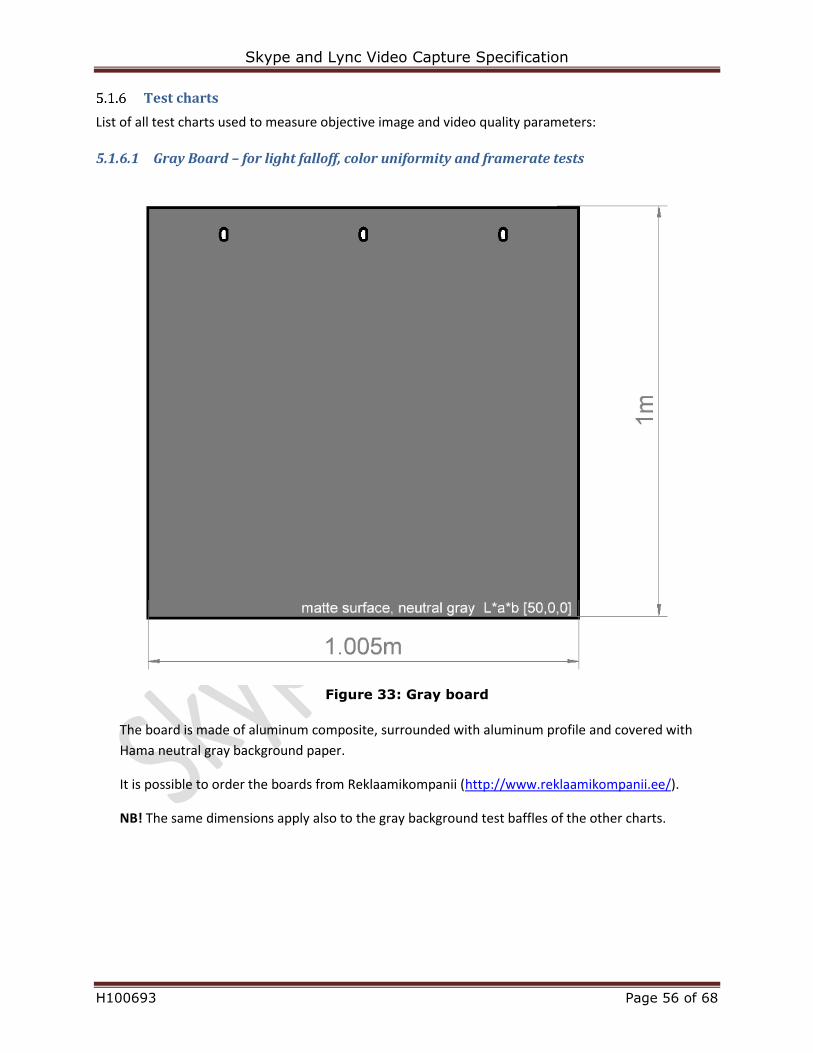
Skype and Lync Video Capture Specification
H100693 Page 56 of 68
Test charts
List of all test charts used to measure objective image and video quality parameters:
5.1.6.1 Gray Board – for light falloff, color uniformity and framerate tests
Figure 33: Gray board
The board is made of aluminum composite, surrounded with aluminum profile and covered with
Hama neutral gray background paper.
It is possible to order the boards from Reklaamikompanii (http://www.reklaamikompanii.ee/).
NB! The same dimensions apply also to the gray background test baffles of the other charts.
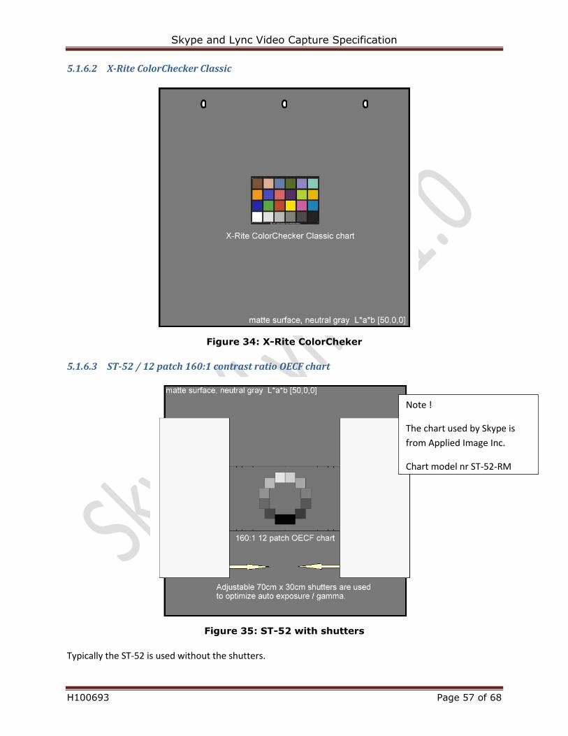
Skype and Lync Video Capture Specification
H100693 Page 57 of 68
5.1.6.2 X-Rite ColorChecker Classic
Figure 34: X-Rite ColorCheker
5.1.6.3 ST-52 / 12 patch 160:1 contrast ratio OECF chart
Figure 35: ST-52 with shutters
Typically the ST-52 is used without the shutters.
Note !
The chart used by Skype is
from Applied Image Inc.
Chart model nr ST-52-RM
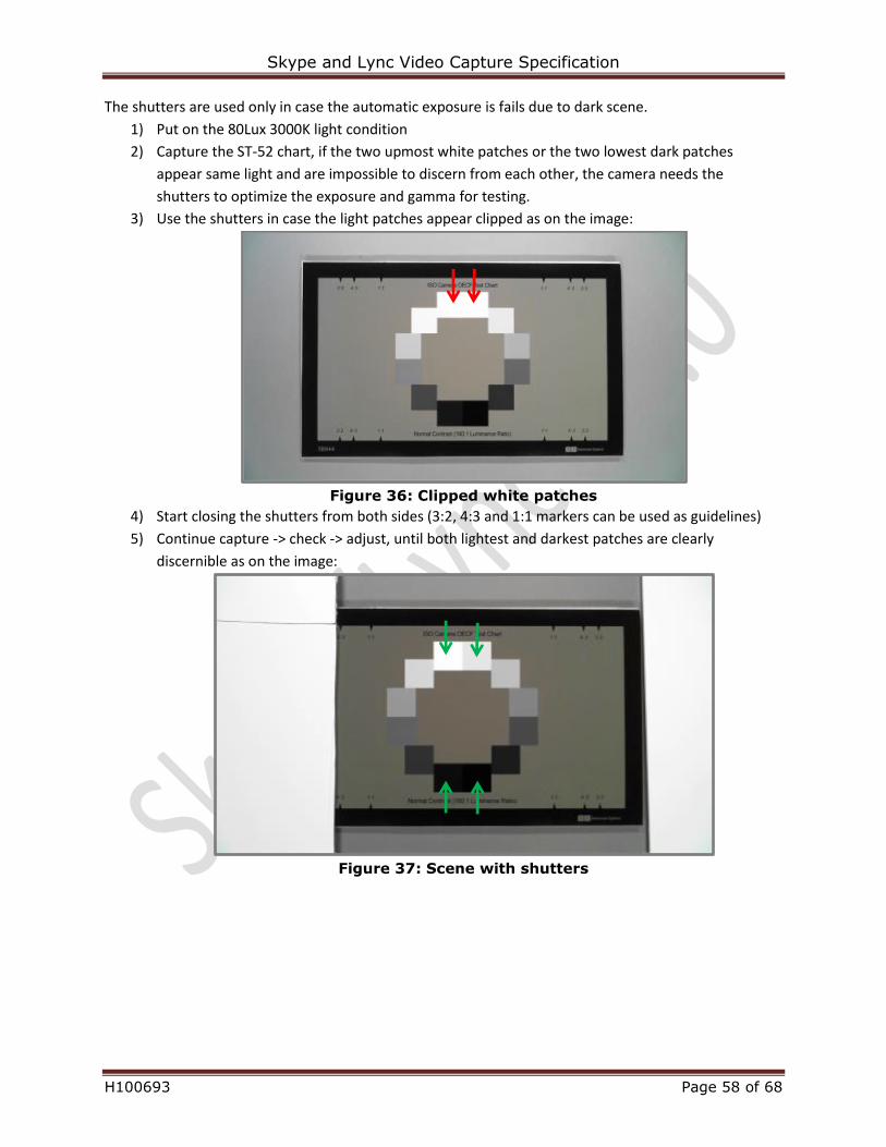
Skype and Lync Video Capture Specification
H100693 Page 58 of 68
The shutters are used only in case the automatic exposure is fails due to dark scene.
1) Put on the 80Lux 3000K light condition
2) Capture the ST-52 chart, if the two upmost white patches or the two lowest dark patches
appear same light and are impossible to discern from each other, the camera needs the
shutters to optimize the exposure and gamma for testing.
3) Use the shutters in case the light patches appear clipped as on the image:
Figure 36: Clipped white patches
4) Start closing the shutters from both sides (3:2, 4:3 and 1:1 markers can be used as guidelines)
5) Continue capture -> check -> adjust, until both lightest and darkest patches are clearly
discernible as on the image:
Figure 37: Scene with shutters
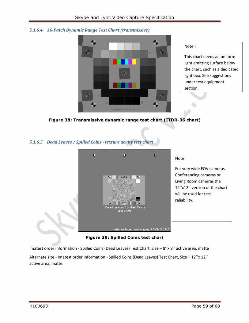
Skype and Lync Video Capture Specification
H100693 Page 59 of 68
5.1.6.4 36-Patch Dynamic Range Test Chart (transmissive)
Figure 38: Transmissive dynamic range test chart (ITDR-36 chart)
5.1.6.5 Dead Leaves / Spilled Coins - texture acuity test chart
Figure 39: Spilled Coins test chart
Imatest order information - Spilled Coins (Dead Leaves) Test Chart, Size – 8’’x 8’’ active area, matte
Alternate size - Imatest order information - Spilled Coins (Dead Leaves) Test Chart, Size – 12’’x 12’’
active area, matte.
Note!
For very wide FOV cameras,
Conferencing cameras or
Living Room cameras the
12’’x12’’ version of the chart
will be used for test
reliability.
Note !
This chart needs an uniform
light emitting surface below
the chart, such as a dedicated
light box. See suggestions
under test equipment
section.
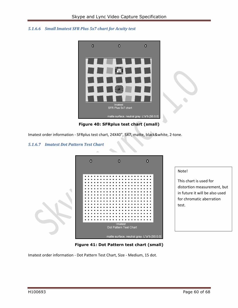
Skype and Lync Video Capture Specification
H100693 Page 60 of 68
5.1.6.6 Small Imatest SFR Plus 5x7 chart for Acuity test
Figure 40: SFRplus test chart (small)
Imatest order information - SFRplus test chart, 24X40", 5X7, matte, black&white, 2-tone.
5.1.6.7 Imatest Dot Pattern Test Chart
Figure 41: Dot Pattern test chart (small)
Imatest order information - Dot Pattern Test Chart, Size - Medium, 15 dot.
Note!
This chart is used for
distortion measurement, but
in future it will be also used
for chromatic aberration
test.
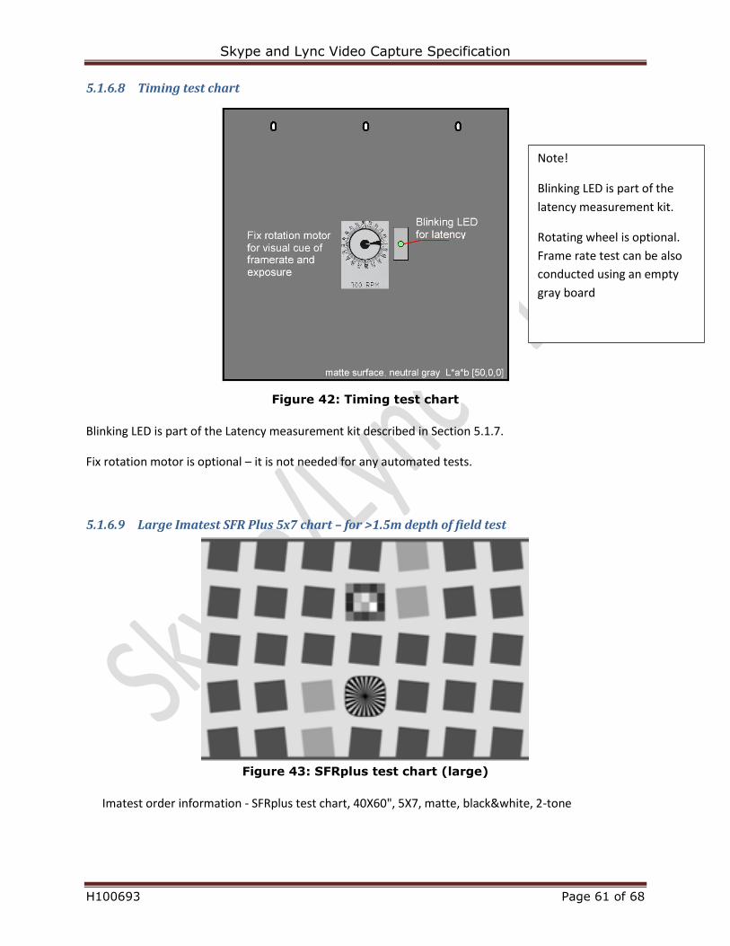
Skype and Lync Video Capture Specification
H100693 Page 61 of 68
5.1.6.8 Timing test chart
Figure 42: Timing test chart
Blinking LED is part of the Latency measurement kit described in Section 5.1.7.
Fix rotation motor is optional – it is not needed for any automated tests.
5.1.6.9 Large Imatest SFR Plus 5x7 chart – for >1.5m depth of field test
Figure 43: SFRplus test chart (large)
Imatest order information - SFRplus test chart, 40X60", 5X7, matte, black&white, 2-tone
Note!
Blinking LED is part of the
latency measurement kit.
Rotating wheel is optional.
Frame rate test can be also
conducted using an empty
gray board
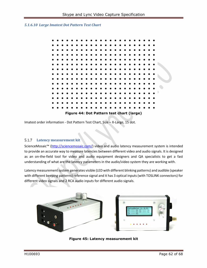
Skype and Lync Video Capture Specification
H100693 Page 62 of 68
5.1.6.10 Large Imatest Dot Pattern Test Chart
Figure 44: Dot Pattern test chart (large)
Imatest order information - Dot Pattern Test Chart, Size – X-Large, 15 dot.
Latency measurement kit
ScienceMosaic™ (http://sciencemosaic.com/) video and audio latency measurement system is intended
to provide an accurate way to measure latencies between different video and audio signals. It is designed
as an on-the-field tool for video and audio equipment designers and QA specialists to get a fast
understanding of what are the latency parameters in the audio/video system they are working with.
Latency measurement system generates visible (LED with different blinking patterns) and audible (speaker
with different beeping patterns) reference signal and it has 3 optical inputs (with TOSLINK connectors) for
different video signals and 2 RCA audio inputs for different audio signals.
Figure 45: Latency measurement kit
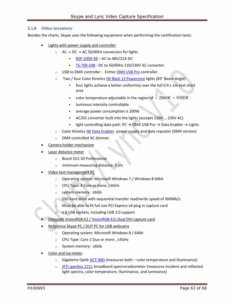
Skype and Lync Video Capture Specification
H100693 Page 63 of 68
Other inventory
Besides the charts, Skype uses the following equipment when performing the certification tests:
Lights with power supply and controller
o AC -> DC -> AC 50/60Hz conversion for lights
RSP-1000-48 – AC to 48V/21A DC
TS-700-248 - DC to 50/60Hz 110/230V AC converter
o USB to DMX controller - Enttec DMX USB Pro controller
o Two / four Color Kinetics iW Blast 12 Powercore lights (83° Beam Angle)
four lights achieve a better uniformity over the full 0.9 x 1m test chart area
color temperature adjustable in the region of – K9002 – K6500
luminous intensity controllable
average power consumption is 200W
AC/DC converter built into the lights (accepts 110V … 230V AC)
light controlling data path: PC → DMX USB Pro → Data Enabler → Lights
o Color Kinetics iW Data Enabler- power supply and data repeater (DMX version)
o DMX controlled AC dimmer.
Camera holder mechanism
Laser distance meter
o Bosch DLE 50 Professional
o minimum measuring distance: 5 cm
Video test managemant PC
o Operating system: Microsoft Windows 7 / Windows 8 64bit
o CPU Type: 4 Core or more, ≥3GHz
o system memory: ≥6Gb
o SSD hard drive with sequential transfer read/write speed of 360Mb/s
o Must be able to fit full size PCI Express x4 plug in capture card
o ≥ 6 USB sockets, including USB 3.0 support
Datapath VisionRGB-E2 / VisionRGB-E2s Dual DVI capture card
Reference Skype PC / DUT PC for USB webcams
o Operating system: Microsoft Windows 8 / 64bit
o CPU Type: Core 2 Duo or more , ≥3GHz
o System memory: ≥6Gb
Color and lux-meter
o Gigahertz Optik HCT-99D (measures both – color temperature and illuminance)
o JETI specbos 1211 broadband spectroradiometer (measures incident and reflected light spectra, color temperature, illuminance, and luminance)
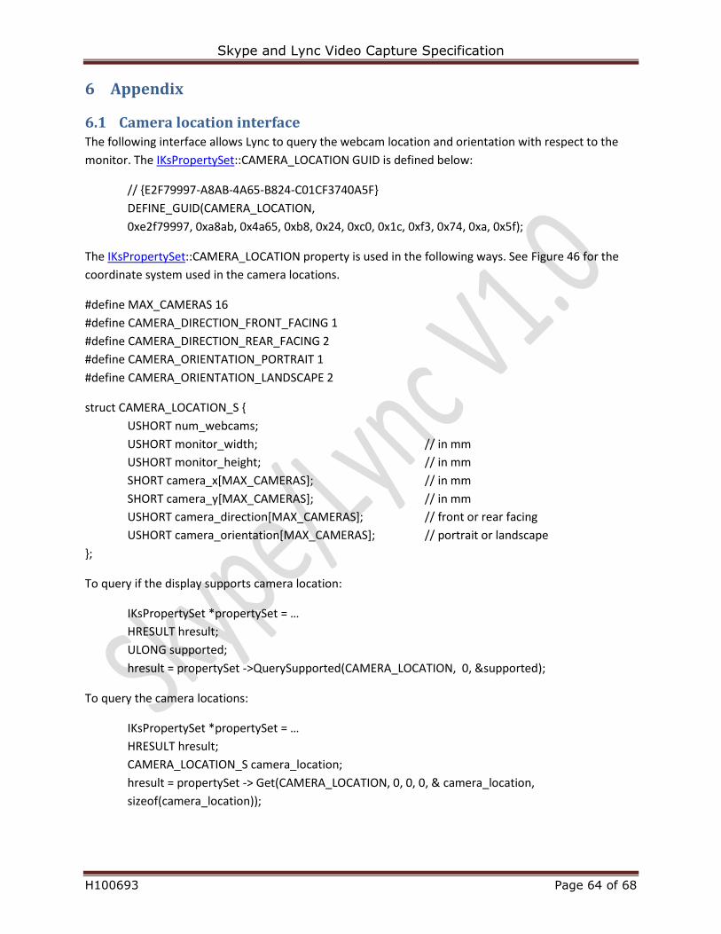
Skype and Lync Video Capture Specification
H100693 Page 64 of 68
6 Appendix
6.1 Camera location interface The following interface allows Lync to query the webcam location and orientation with respect to the
monitor. The IKsPropertySet::CAMERA_LOCATION GUID is defined below:
// {E2F79997-A8AB-4A65-B824-C01CF3740A5F}
DEFINE_GUID(CAMERA_LOCATION,
0xe2f79997, 0xa8ab, 0x4a65, 0xb8, 0x24, 0xc0, 0x1c, 0xf3, 0x74, 0xa, 0x5f);
The IKsPropertySet::CAMERA_LOCATION property is used in the following ways. See Figure 46 for the
coordinate system used in the camera locations.
#define MAX_CAMERAS 16
#define CAMERA_DIRECTION_FRONT_FACING 1
#define CAMERA_DIRECTION_REAR_FACING 2
#define CAMERA_ORIENTATION_PORTRAIT 1
#define CAMERA_ORIENTATION_LANDSCAPE 2
struct CAMERA_LOCATION_S {
USHORT num_webcams;
USHORT monitor_width; // in mm
USHORT monitor_height; // in mm
SHORT camera_x[MAX_CAMERAS]; // in mm
SHORT camera_y[MAX_CAMERAS]; // in mm
USHORT camera_direction[MAX_CAMERAS]; // front or rear facing
USHORT camera_orientation[MAX_CAMERAS]; // portrait or landscape
};
To query if the display supports camera location:
IKsPropertySet *propertySet = …
HRESULT hresult;
ULONG supported;
hresult = propertySet ->QuerySupported(CAMERA_LOCATION, 0, &supported);
To query the camera locations:
IKsPropertySet *propertySet = …
HRESULT hresult;
CAMERA_LOCATION_S camera_location;
hresult = propertySet -> Get(CAMERA_LOCATION, 0, 0, 0, & camera_location,
sizeof(camera_location));
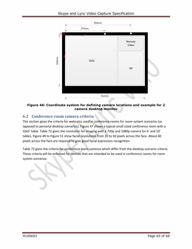
Skype and Lync Video Capture Specification
H100693 Page 65 of 68
Data
RemoteVideo
IM
454mm.
552mm.
34
3m
m.
275mm.
(0,0) X
Y
Figure 46: Coordinate system for defining camera locations and example for 2
camera desktop monitor
6.2 Conference room camera criteria This section gives the criteria for webcams used in conference rooms for room system scenarios (as
opposed to personal desktop scenarios). Figure 47 shows a typical small sized conference room with a
10x5’ table. Table 72 gives the resolution for imaging with a 720p and 1080p camera for 6’ and 10’
tables. Figure 48 to Figure 51 show facial resolutions from 20 to 50 pixels across the face. About 40
pixels across the face are required to give good facial expression recognition.
Table 73 gives the criteria for conference room cameras which differ from the desktop scenario criteria.
These criteria will be enforced for devices that are intended to be used in conference rooms for room
system scenarios.
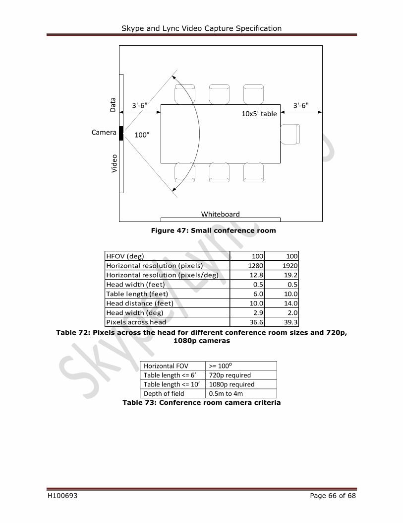
Skype and Lync Video Capture Specification
H100693 Page 66 of 68
Whiteboard
Vid
eo10x5' tableD
ata
Camera 100°
3'-6" 3'-6"
Figure 47: Small conference room
HFOV (deg) 100 100
Horizontal resolution (pixels) 1280 1920
Horizontal resolution (pixels/deg) 12.8 19.2
Head width (feet) 0.5 0.5
Table length (feet) 6.0 10.0
Head distance (feet) 10.0 14.0
Head width (deg) 2.9 2.0
Pixels across head 36.6 39.3 Table 72: Pixels across the head for different conference room sizes and 720p,
1080p cameras
Horizontal FOV >= 100⁰
Table length <= 6’ 720p required
Table length <= 10’ 1080p required
Depth of field 0.5m to 4m Table 73: Conference room camera criteria
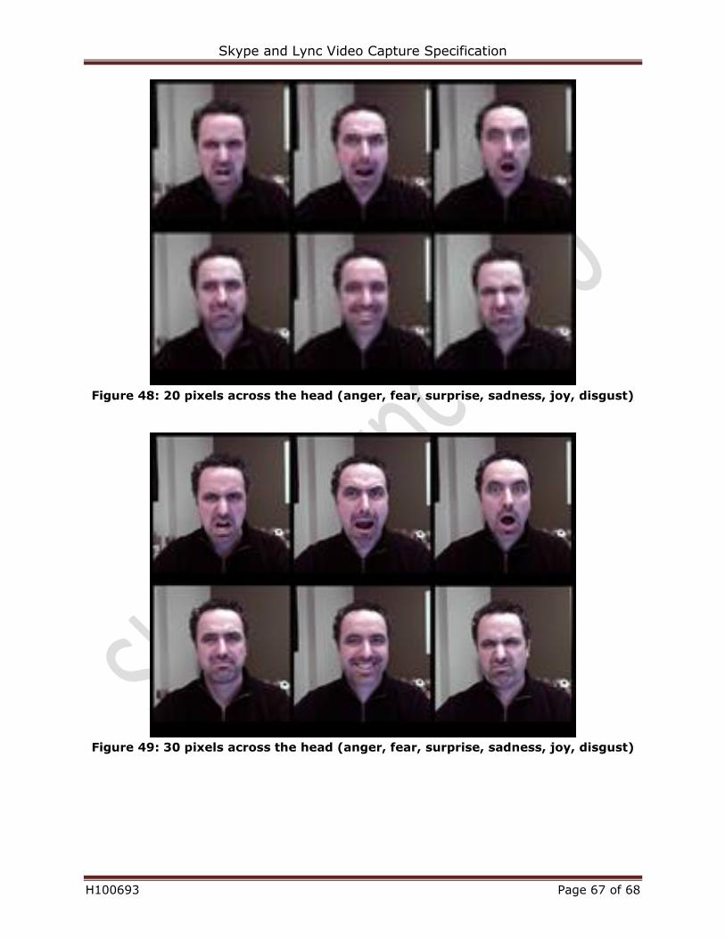
Skype and Lync Video Capture Specification
H100693 Page 67 of 68
Figure 48: 20 pixels across the head (anger, fear, surprise, sadness, joy, disgust)
Figure 49: 30 pixels across the head (anger, fear, surprise, sadness, joy, disgust)
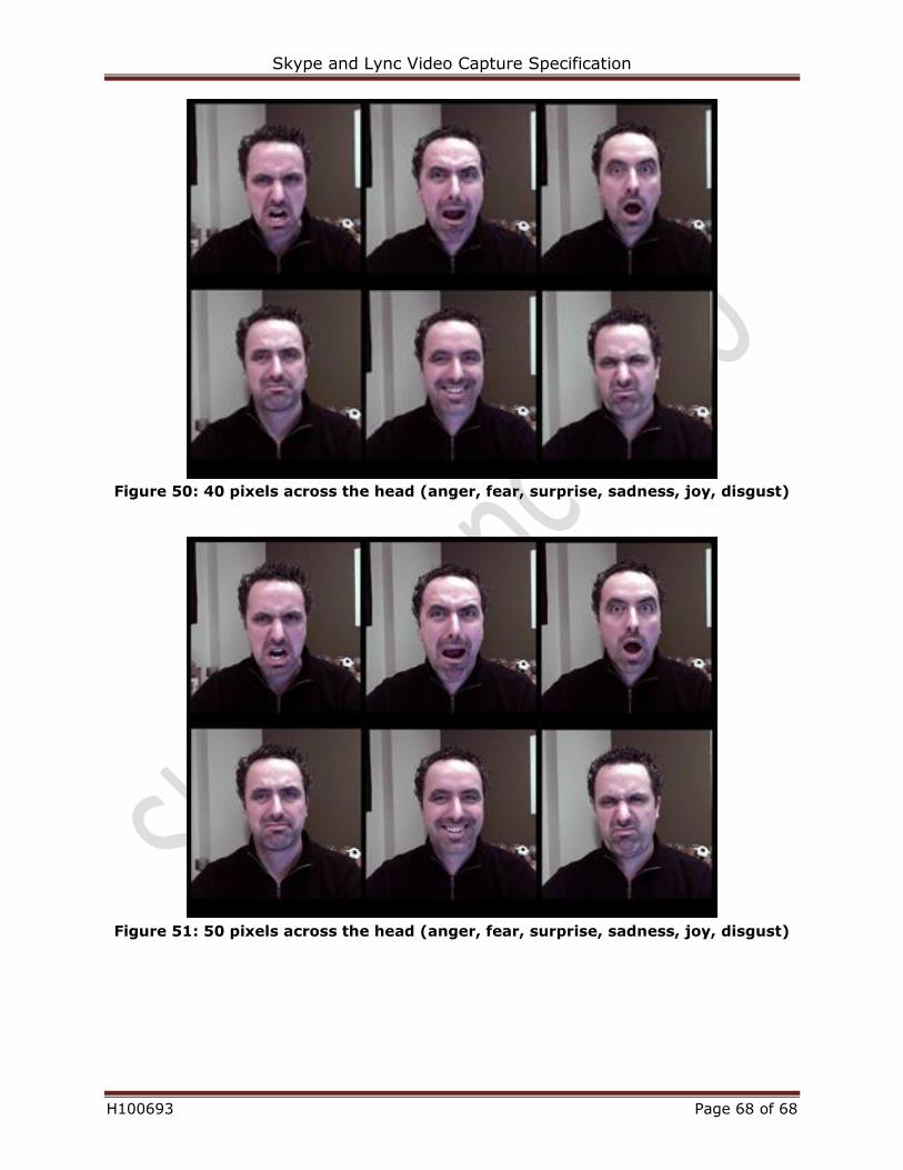
Skype and Lync Video Capture Specification
H100693 Page 68 of 68
Figure 50: 40 pixels across the head (anger, fear, surprise, sadness, joy, disgust)
Figure 51: 50 pixels across the head (anger, fear, surprise, sadness, joy, disgust)