slide unit - smc
TRANSCRIPT

CX2/CXWM/CXWL Series
Slide Unit
685
ø10
ø16
ø20
ø25
ø32
ø10
ø16
ø20
ø25
ø32
25 50 75 100 125 150 175 200
659
ø10
ø15
ø25
650
<Fixing the plate> The housing moves.
<Fixing the housing> The plate moves.
Series Variations
Slide unit
Bearingtype Model
Boresize
Stroke (mm)
(2)
(2)
(3)
(2)
(3)
(3)
(3)
Accessory
Note 1) Only type E (Reed switch) is applicable as an auto switch when mounting a housing of ø10.Note 2) The shock absorbers are to be mounted on the both sides for the 25 stroke of the CXWM10 to 25 series.Note 3) The shock absorber is to be mounted on one side of the plate for the 25 stroke of the CXWM20, CXWM32, CXWL32 series and the 50 stroke of the CXWM32 series.
Plate
mou
nting
(1)
(1)
(1)
Autoswitchmounting
Page
With
end
lock
Shock
abs
orbe
r
Adjusti
ng b
olt
Housin
g m
ount
ing
Provided with shock absorbers to absorb impact and noise.The slide unit can absorb energy in a wide range, in high speed, low-load applications to low speed, high-load applications, without requiring adjustments.
Ensures high positional accuracy.A high level of positional accuracy can be attained because the two parallel piston rods prevent the rods from rotating, and the workpiece mounting surface and the parallelism of the piston rods are made highly precise.
Mountable on the housing or on the plate.The slide unit can be mounted on the housing or on the plate, depending on the application. It can also be bolted from the bottom or from the top. The piping can be fitted to the port in any of the three positions, according to how the unit is mounted.
Auto switches can be installed.
Smooth operation and high thrust.
CX2 SeriesDouble rod type(Basic type, compact)
Mounting from the upper side
Mounting from the upper side
Mounting from the bottom side
Mounting from the bottom side
Bal
l bu
shin
g b
eari
ng
Slid
e b
eari
ng
CXWM SeriesBuilt-in shockabsorber type
CXWL SeriesBuilt-in shockabsorber type
Housing Plate
Slide Bearing/CX2:ø10, ø15, ø25 CXWM:ø10, ø16, ø20, ø25, ø32Ball Bushing Bearing/CXWL:ø10, ø16, ø20, ø25, ø32
647
CX2
CXW
CXT
CXSJ
CXS
D-
-X
CX2

32
16
15
25
20
10
CX2N25
CX2N15
CX2N10
20
10
0.1
0.2
0.3
0.4
0.5
1
2
3
4
5
Allo
wab
le M
1 (=
M3)
mom
ent (
N·m
)
25 50 75 100 125 150 175 200
Cylinder stroke (mm)
30
20
0.5
1
3
2
5
4
10
Load
mas
s (k
g)
10 50 100 200 300 500 1000
Cylinder speed (mm/s)
CXW32
CXWL25
CXW16
CXW10
CX2N15-∗B
CX2N10-∗B
CXW20CX2N25-∗B, CXWM25
CX2NCXWM (Slide bearing)CXWL (Ball bushing bearing)
Maximum Allowable Moment: CX2N, CXWM, CXWL
Allowable Kinetic Energy
Operate within the operating range and under the allowable moment indicated in the table below.
Load mass and cylinder speed should be observed within the range given in the graph below.To adjust the cylinder speed, use a speed controller.
Bore size (mm)
CX2N
CXWM
CXWL
Allowable Moment (M2) (N·m)
Note) M2 is steady regardless of the strokes.
10 1615 20 25 32
0.098
0.108
0.108
0.294
—
—
—
0.549
0.549
—
0.809
0.809
1.029
1.029
1.201
—
2.695
2.695
CX2/CXWM/CXWL Series
Prior to Use
648

1. Changing from the non-auto switch specifications to the auto switch specifications2. Changing mounting type of the auto switch specifications
CX2N
CDPX2N S ·······Table (1)
CDBX2N M ·······Table (2)
CDPX2N S ·······Table (1)
CDBX2N M ·······Table (2)
Table (1) Plate Mounting Type with Auto Switch (CDPX2N–) Component Parts for Mounting Switches and No. of Component Parts
Table (2) Housing Mounting Type with Auto Switch (CDBX2N–) Component Parts for Mounting Switches and No. of Component Parts
Component parts Material
ø10 ø15 ø25Assembly model no. for mounting switch
Switch mounting block
Block mounting screw
Switch mounting screw
Hexagon nut
Magnet
Socket
Plug
Aluminum alloy
Chrome steel/Zinc chromated
Chrome steel/Zinc chromated
Carbon steel/Zinc chromated
–
Carbon steel/Electroless nickel plated
Carbon steel/Nickel plated
1
2
2
2
1(2)(2)
2
2
1
2
2
2
–
–
2
1
2
2
2
–
–
–
CDPX2N10S-
CDPX2N15S-
CDPX2N25S-
Component parts Material
ø10 ø15 ø25Assembly model no. for mounting switch
Magnet mounting block assembly
Switch mounting rail
Spacer
Block mounting screw
Screw for mounting rail
Switch mounting screw
Hexagon nut
Hexagon socket head plug
Aluminum alloy
Aluminum alloy
Aluminum alloy/Anodized
Chrome steel/Zinc chromated
Chrome steel/Zinc chromated
Chrome steel/Zinc chromated
Carbon steel/Zinc chromated
Chrome steel/Zinc chromated
1
–
2
2
–
2
2
2
1
1
–
2
2
2
2
2
1
1
–
2
2
2
2
–
CDBX2N10M-
CDBX2N15M-
CDBX2N25M-
CX2 Series
Note 1) “” mark indicates strokes.Note 2) In the case of ø10, the 25 mm stroke has two magnets that are bonded in the holes on
the side of the housing. Those with strokes of 50 mm to 100 mm have one magnet. Those with other bore sizes have a built-in magnet in their housings.
Note 1) “” mark indicates strokes.Note 2) For ø10, CX2N10- can be changed to CDBX2N10-, but note that CDPX2N10
cannot be changed to CDBX2N10-.
Without auto switch:
Plate mounting typewith auto switch:
Housing mounting typewith auto switch:
Plate mounting typewith auto switch:
Housing mounting typewith auto switch:
1. In the CX2 series, to change from the specification without auto switch to the plate mounting type with auto switch or to the housing mounting type with auto switch, refer to tables (1) and (2) before ordering.
2. In the CX2 series, to change from the plate mounting type with an auto switch to the housing mounting type with an auto switch or vice versa, refer to tables (1) and (2) before ordering.
CX2 Series
Prior to Use
649
CX2
CXW
CXT
CXSJ
CXS
D-
-X
CX2
Cushion (Option)
CX2
C X2
N
N
15
15
B
BCylinder with auto switch
100
100 J79WDB
Symbol
DB
DP
Specifications/Mounting
With auto switch/Housing mounting
With auto switch/Plate mounting
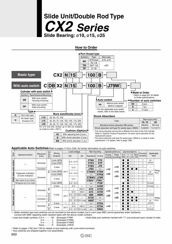
Bore size/Stroke (mm)ø10
ø15
ø25
25, 50, 75, 100
25, 50, 75, 100, 125, 150, 175, 200
25, 50, 75, 100, 125, 150, 175, 200
Applicable Auto Switch/Refer to page pages 1719 to 1827 for further information on auto switches.
TypeN
H
Non-lube type
Air-hydro type (Except ø10)
Nil
B
BS
With adjusting bolt (2 pcs.)
With shock absorber (2 pcs.)
With shock absorber (1 pc.)
∗ Refer to page 651 for Made to Order specifications.
For ø15 and ø25, strokes up to 300 are available as made-to-order. (-XB11)
3-wire (NPN)3-wire (PNP)
2-wire
3-wire (NPN)3-wire (PNP)
2-wire
4-wire (NPN)
Grommet
Connector
Grommet
—
5 V, 12 V
12 V
5 V, 12 V
12 V
5 V, 12 V
24 V
ICcircuit
F7NVF7PVF7BVJ79C
F7NWV—
F7BWVF7BAV∗∗
—
F79F7PJ79—
F79WF7PWJ79WF7BA∗∗F79F
—
Diagnostic indication(2-color indicator)
Water resistant (2-color indicator)With diagnostic output (2-color indicator)
ø15
ø25
ø10
ø15
ø25
Relay,PLC
ø10
ø10
ø15
ø25
ø15
ø25
—
—
ICcircuit
ICcircuit
IC circuit
IC circuit
IC circuit
IC circuit
—
—
—
—
—
Relay,PLC
3-wire
2-wire
3-wire
2-wire
Grommet
Connector
Grommet
—200 V100 V
100 V or less—
24 V or less—
100 V100 V or less
5 V—
12 V5 V, 12 V
12 V5 V, 12 V
5 V12 V
5 V, 12 V
——
24 V
—
24 V
—A72A73A80
A73CA80C
———
A76HA72HA73HA80H
——
E76AE73AE80A
—
Special function Electricalentry
Pre-wiredconnector
Wiring(Output)
Load voltage
ACDC
Applicable cylinder size Lead wire length (m)
0.5(Nil)
3(L)
5(Z)
Applicableload
Rail mounting
Housingmounting
Platemounting
None(N)Perpendicular In-line
Port thread typeBore sizeø10, ø15
ø25
TypeM threadRc 1/8
NPT 1/8G 1/8
Symbol
Nil
TNTF
Number of auto switchesNilSn
2 pcs. 1 pc.
“n” pcs.
Auto switch
NilWithout auto switch
(Built-in magnet)
Made to Order
∗ For the applicable auto switch model, refer to the table below.
Shock Absorbers
10, 15Standard (shock absorber RB series)
Shock absorber soft type RJ series type (-XB22)
TypeBore size (mm)
RB0805RJ0806H
25RB1006RJ1007H
∗ The shock absorber service life is different from that of the CX2 cylinder.Refer to “Specific Product Precautions” for each shock absorber for the replacement period.
∗ The shock absorber soft type RJ series type (-XB22) is a made to order specification. For details, refer to page 1296.
How to Order
With auto switch
Indica
tor lig
ht
∗ Lead wire length symbols: 0.5 m ·········· Nil (Example) F79W 3 m ·········· L (Example) F79WL 5 m ·········· Z (Example) F79WZ None ·········· N (Example) J79CN
∗ Refer to pages 1192 and 1193 for details of auto switches with a pre-wired connector.∗ Auto switches are shipped together (not assembled).
∗∗ Water resistant type auto switches can be mounted on the above models, but in such case SMC cannot guarantee water resistance.Consult with SMC regarding water resistant types with the above model numbers.
Yes
Yes
Yes
Yes
NoNo
No
Type
So
lid s
tate
au
to s
wit
chR
eed
au
to s
wit
ch
∗ Solid state auto switches marked with “” are produced upon receipt of order.
Slide Unit/Double Rod Type
CX2 SeriesSlide Bearing: ø10, ø15, ø25
Applicable Auto Switches/Refer to pages 1119 to 1245 for further information on auto switches.
Basic type
650

When operating an actuator with a small diameter and a short stroke at a high frequency, the dew condensation (water droplet) may occur inside the piping depending on the conditions.Simply connecting the moisture control tube to the actuator will prevent dew condensation from oc-curring. For details, refer to the IDK series in the Best Pneumatics No. 6.
MoistureControl TubeIDK Series
-XB11-XB13-XB22-XC22
Long stroke type
Low speed cylinder (5 to 50 mm/s)
Shock absorber soft type RJ series type
Fluororubber seals
Symbol Specifications
Made to Order Specifications(For details, refer to pages 1247 to 1440.)
-X138-X146-X168-X169
Adjustable stroke
Hollow piston rod
CX helical insert thread
2 built-in magnets
Symbol Specifications
Note) Theoretical output (N) = Pressure (MPa) x Piston area (mm2)
(N)
ModelRod size
(mm)
6
8
14
Piston area(mm2)
101
207
597
Operating pressure (MPa)
0.2
20
41
119
0.3
30
62
179
0.4
40
83
239
0.5
51
104
299
0.6
61
124
358
0.7
71
145
418
0.8
81
166
478
0.9
91
186
537
CX2N10CX215CX225
Table (1) Air-hydro/Piston Speed
Shock Absorber Specifications
Theoretical Output
CX2N10CX215CX225
CX2N10CX215CX225CX2N10CX215CX225
Fluid
Proof pressure
Max. operating pressure
Min. operating pressure
Ambient and fluid temperature
Piston speed (Non-lube)
Cushion
Stroke adjustable range
Accessory (Option)
1.5 MPa
1.0 MPa
0.15 MPa
0.10 MPa
–10°C to +60°C
Straight knock pin (2 pcs.), Adjusting bolt (-X138)(2)
Shock absorber
With shock absorber (Option)
Standard stroke: ±2 mm
9.8 N
29.4 N
58.8 N
±0.1°±0.04°±0.02°
Non-lube
Air
0.15 MPa
30 to 200 mm/s
30 to 500 mm/s
—
Type Air-hydro type
Hydraulic fluid
Refer to Table (1).With adjusting bolt
With shock absorber
Max. load mass (1)
Non-rotating accuracyExcept piston rod deflection( )
Specifications
Plate mounting
Refer to the below. Note 1)
5 to 40 mm/s
Housing mounting
5 to 50 mm/s
5 to 100 mm/s
Model
CX2H15CX2H25
Extended
Retracted
Shock absorber
Applicable slide unit
Maximum energy absorption (J)
Stroke absorption (mm)
Max. collision speed (m/sec)
Max. operating frequency (cycle/min)
Max. allowable thrust (N)
Ambient temperature range (°C)
Spring force (N)
Weight (g)
RB0805CX2N10, CX215
RB1006CX225
0.98
5
80
147
1.96
3.83
15
0.05 to 5
–10 to 80
3.92
6
70
353
4.22
6.18
25
Made to Order: Individual Specifications(For details, refer to pages 706 to 708.)
Note 1) Place the center of gravity of the load as close to the center of the slide unit as possible during operation. If they are placed far apart, consult with SMC.
Note 2) “-X138” has a stroke adjustable range of 12.5 mm on one side.
Note 1) Consult with SMC when the air-hydro type is mounted on a plate.Note 2) Consult with SMC when units are used at a low speed (10 mm/s or faster) (when
intermediate stops are not required) since -XB13 (Low speed specification) is available. Note 3) When using the air-hydro type, use the double side hydro unit.
∗The above shows the maximum absorption energy per cycle. Accordingly, the operating frequency can be increased in accordance with the absorption energy.
∗The shock absorber service life is different from that of the cylinder body depending on the operating conditions. Refer to the RB Series Specific Product Precautions for the replacement period.
651
Slide Unit/Double Rod Type CX2 Series
CX2
CXW
CXT
CXSJ
CXS
D-
-X
CX2

ModelBasic stroke (mm)
25
50
75
100
125
—
150
—
175
—
200
—
CX2N10CX215CX225
(kg)
ModelBasic stroke (mm)
25
0.17
0.23
0.93
50
0.22
0.34
1.15
75
0.27
0.45
1.36
100
0.32
0.56
1.58
125
—
0.67
1.80
150
—
0.78
2.01
175
—
0.89
2.29
200
—
1.00
2.45
CX2N10CX215CX225
F
Right
E
Left
D
Right
C
Left
B
Left
A
Right
Pressure port
Operating direction
(mm)
ModelStroke
9.8
29.4
58.8
100
0.07
0.08
0.02
200
—
0.28
0.08
CX2N10CX215CX225
(mm)
Model L
10
10
15
øD
4
5
6
Part no.∗
MS4-10
MS5-10
MS6-15
CX2N10CX215CX225
(mm)
ModelStroke
2.94
4.90
9.81
100
0.30
0.22
0.09
200
—
1.0
0.25
150
—
0.50
0.16
50
0.06
0.09
0.03
CX2N10CX215CX225
∗ Manufactured by Misumi Trading Ltd.
∗ There are 9 possible reciprocating piping methods.
Operating Direction with Different Pressure Ports
Deflection of Piston Rod byCenter Loading (Reference)
AccessoryStraight Knock Pin (Option)
Load (N)
Load (N)
Standard Stroke Table
Weight
Operating direction of housing when the plate is fixed
When center loading is added to the center of the housing
When center loading is added to the center of the plate
Note) The values denote the total width of the deflections in the upward/downward direction.
Standard side of housing(Mounting side)
Left Right
Operating direction of the housing
Deflection width
652
CX2 Series

CX2N15, 25
CX2N10
Construction/Parts List, Seal List
No.
1
2
3
4
5
6
7
8
9
10
11
12
13
14
15
16
Description Material Note
Parts List
Rod cover
Housing
Piston
Piston rod
Plate
Lock nut
Adjusting bolt
Set screw (For fixing rods)
Pin
Retaining ring
Plug
Magnet
Ball fixing screw
Spring
Type CR retaining ring
Round type R retaining ring
Aluminum bearing alloy
Aluminum alloy
Aluminum alloy
Carbon steel piping for machine constructions
Aluminum alloy
Carbon steel
Chromium steel
Chromium steel
Carbon steel
Carbon tool steel
Carbon steel
—
Chromium steel
Stainless steel
Carbon tool steel
Carbon tool steel
Hard anodized
Hard chrome plated
Anodized
Nickel plated
Zinc chromated
Zinc chromated
Quenched
Phosphate coated
Nickel plated
Zinc chromated
Phosphate coated
Model
CX2N10
CX2N15
CX2N25
Kit no.
CX2N10-PS
CX2N15-PS
CX2N25-PS
Contents
A set of @0, @1, @3 listed above
No.
17
18
19
20
21
22
23
Description Material Note
Parts List
Steel ball
Socket
Gasket
Rod seal
Piston seal
Piston gasket
Cylinder tube gasket
High carbon chrome bearing steel
Brass
NBR
Heat treated
Electroless nickel plated
Replacement Parts: Seal Kit
q
w
e
r
t
yu i
o !0@1 @2@3
!1
!3 !6!7
!8!9
@0
qw e rt yuio!0 @1 @2 @3!2
!3
!4!5!6
!7
@0
∗ Seal kit includes @0, @1, @3. Order the seal kit, based on each bore size.(The piston gasket @2 is not replaceable.)
∗ Since the seal kit does not include a grease pack, order it separately.Grease pack part no.: GR-S-010 (10 g)
Slide Unit/Double Rod Type CX2 Series
653
CX2
CXW
CXT
CXSJ
CXS
D-
-X
CX2

Model F
9.5202525
G
19.5303535
L
386388
113
P
48526792
Q
103153203253
With adjusting boltZZ132182232282
With shock absorberZZ176226276326
CX2N10-25CX2N10-50CX2N10-75CX2N10-100
(mm)
R
28324772
S
275277102
SS
6792117142
Z
94144194244
Auto switch model Hw23
23
2223232430
Ht15
15
1517.515
17.515
Hv10.5
11.5
11.517.51417
11.5
D-A7, D-A8D-F7, D-J79, D-J79W, D-F7PW, D-F79F, D-F7BA, D-F7NTD-A7H, D-A80HD-A73C, D-A80CD-F7VD-J79CD-F7LF
Note 1) The dimensions show D-A7 and D-A8.
Housing mounting type with auto switchCDBX2N10 Stroke Stroke
Plate mounting type with auto switchCDPX2N10
ø10 Basic Type: CX2N10 Strokes: 25 to 100
CX2 Series
4 x ø6.5 counterbore depth 3.5
2 x 2 x ø4Max. 7
Max. ZZ
Max. ZZMax. 32
4 x ø3.3 through
Adjusting bolt2 x ø4
Socket
2 x M4 x 0.7 thread depth 8
2 x 2 x M4 x 0.7 thread depth 8
2 x M5 x 0.8 Cylinder port
2 x M5 x 0.8Cylinder port
Plug (M-5P)
2 x M8 x 1.0
Socket connection port (2 positions of hexagon socket head cap screws)4 x M4 x 0.7 depth 5
depth 3.3
depth 5
Shock absorber
With shock absorber
Bottom through-hole ø3.3 through
2 x ø3.3 through2 x ø6.5 counterbore
Note 1) The dimensions show D-E7A and D-E80A.
Note 2) For only 25 strokes, two magnets for auto switches are installed in the housing.
Magnet mounting block
Auto switch
Auto switch
Plugs (2 pcs.)
654

Auto switch model Hw23
23
2223232430
Hs12.5
12.5
12.515
12.515
12.5
Ht15
15
1517.515
17.515
D-A7, D-A8D-F7, D-J79, D-J79W, D-F7PW, D-F79F, D-F7BA, D-F7NTD-A7H, D-A80HD-A73C, D-A80CD-F7VD-J79CD-F7LF
Model F
24.524.52727
39.552
64.577
L
386388
113138163188213
P
2045659090909090
Q
106156206256306356406456
S
275277102127152177202
With adjusting boltZZ128178228278328278428478
With shock absorberZZ178228278328378428478528
CX215-25CX215-50CX215-75CX215-100CX215-125CX215-150CX215-175CX215-200
(mm)
SS
6994119144169194219244
Z
96146196246296346396446
Note 1) The dimensions show D-A7 and D-A8.
Auto switch model Hw23
23
2223232430
Ht15
15
1517.515
17.515
Hv10.5
11.5
11.517.51417
11.5
D-A7, D-A8D-F7, D-J79, D-J79W, D-F7PW, D-F79F, D-F7BA, D-F7NTD-A7H, D-A80HD-A73C, D-A80CD-F7VD-J79CD-F7LF
Note 1) The dimensions show D-A7 and D-A8.
Housing mounting type with auto switchCDBX2 15
Plate mounting type with auto switchCDPX2 15
ø15 Basic Type: CX2 15 Strokes: 25 to 200
StrokeStroke
Slide Unit/Double Rod Type CX2 Series
Max. ZZ
Max. ZZMax. 31
Shock absorber
With shock absorber
4 x M5 x 0.8thread depth 10
3 x M5 x 0.8thread depth 10
2 x M8 x 1.0Adjusting bolt
2 x 2 x M5 x 0.8Hexagon socket head cap plug
2 x 2 x ø4.3 through
4 x ø4.2 through
2 x 2 x ø8 counterbore depth 4
4 x ø7.6 counterbore depth 4.4
(ø5H7 hole pitch)
2 x M5 x 0.8Cylinder port
2 x ø5H7 depth 6+0.0120
2 x ø5H7
Depth 6
+0.012 0
Note 2) For only 25 strokes, two magnets for auto switches are installed to the magnet mounting block.
Note 2) For only 25 strokes, two magnets for auto switches are installed in the housing.
Magnet mounting blockAuto switch
Auto switch
Plugs (2 pcs.)
655
CX2
CXW
CXT
CXSJ
CXS
D-
-X
CX2

Auto switch model Hw23
23
2223232430
Hs12.5
12.5
12.515
12.515
12.5
Ht15
15
1517.515
17.515
D-A7, D-A8D-F7, D-J79, D-J79W, D-F7PW, D-F79F, D-F7BA, D-F7NTD-A7H, D-A80HD-A73C, D-A80CD-F7VD-J79CD-F7LF
Model F
28.531
33.533.546
58.571
83.5
L
436691
116141166191216
P
2545659090909090
Q
125175225275325375425475
S
275277102127152177202
With adjusting boltZZ153203253303353403453503
With shock absorberZZ203253303353403453503553
CX225-25CX225-50CX225-75CX225-100CX225-125CX225-150CX225-175CX225-200
(mm)
SS
82107132157182207232257
Z
109159209259309359409459
Note 1) The dimensions show D-A7 and D-A8.
Auto switch model Hw23
23
2223232430
Ht15
15
1517.515
17.515
Hv10.5
11.5
11.517.51417
11.5
D-A7, D-A8D-F7, D-J79, D-J79W, D-F7PW, D-F79F, D-F7BA, D-F7NTD-A7H, D-A80HD-A73C, D-A80CD-F7VD-J79CD-F7LF
Note 1) The dimensions show D-A7 and D-A8.
ø25 Basic Type: CX2 25 Strokes: 25 to 200
Housing mounting type with auto switchCDBX2 25
Plate mounting type with auto switchCDPX2Stroke 25 Stroke
CX2 Series
2 x 2 x ø9.5 counterbore depth 5
2 x 2 x ø5.2 through
2 x 2 x Rc (PT) 1/8
2 x Rc (PT) 1/8
Plug Rc (PT) 1/8
(ø6 H7 hole pitch)
2 x ø6H7 depth 8+0.0120 4 x M6 x 1.0
thread depth 12
3 x M6 x 1.0thread depth 12
Cylinder portDimensions at 25 strokes
Max. ZZMax. 31
Shock absorberRB1006
With shock absorberMax. ZZ
2 x M10 x 1.0Adjusting bolt
4 x ø5.5 through
4 x ø9.5 counterboredepth 5.5
2 x ø6H7
Depth 8
+0.012 0
Note 2) For only 25 strokes, two magnets for auto switches are installed to the magnet mounting block.
Note 2) For only 25 strokes, two magnets for auto switches are installed in the housing.
Magnet mounting blockAuto switchAuto switch
Plugs (2 pcs.)Rc (PT) 1/8
656

Auto switch modelApplicable cylinder size
10
6
15 25
6 6—
— 2.5
2.5 2.5
2.5
3
Auto switch type Model Features
With timer
Applicable cylinder size
ø10, ø15, ø25
Plate mountingHousing mounting
ø15, ø25
Electrical entry (Fetching direction)
D-F7NT Grommet (In-line)
Besides the models listed in How to Order, the following auto switches are applicable.Refer to pages 1119 to 1245 for the detailed specifications.
∗ With pre-wired connector is also available for D-F7NT type. For details, refer to pages 1119 and 1193.∗ It is impossible to mount solid state auto switches to the housing mounting ø10.
Solid state
— —6
Platemounting
Housingmounting
Housingmounting
Platemounting
Housing mounting
D-A7/A80D-A7H/A80HD-A73C/A80C
D-F7/J79D-F7V/J79CD-F7W/F7WVD-F7BA/F7BAVD-F79F/F7NT
D-E7A/E80A
(mm)
Operating Range
∗ Since the operating range is provided as a guideline including hysteresis, it cannot be guaranteed (assuming approximately ±30% dispersion). It may vary substantially depending on an ambient environment.
657
Slide Unit/Double Rod Type CX2 Series
CX2
CXW
CXT
CXSJ
CXS
D-
-X
CX2