slot 1 - img.acuitybrands.com
TRANSCRIPT

Page 1
marklighting.com | 800-705-SERV (7378) | © 2020-2021 Acuity Brands Lighting, Inc. All Rights Reserved. We reserve the right to change design, materials and finish in any way that will not alter installed appearance or reduce function and performance.
S P E C I F I C AT I O N S TYPE:
PROJECT:
S1LWD WALL 11/04/21
SLOT 1DIRECT WALL
• 200 to 1000 lumens per foot
• Up to 117 Lumens per Watt
• Three distributions: Lambertian, Wall Graze and Asymmetric
• Multiple lens treatment options include drop and edge view
• Shielding provided by integrated deep cell quiet ceiling baffle
• Powered and controlled by Modulus remote driver kit that combines all power and control system inputs into a single feed cord.
• Flicker free dimming to dark (0.01%) enabled by Modulus power and control architecture with integrated digital nLight® module for system networking
• Total System Integration features 5-year limited warranty by Acuity Brands, covers all components and construction
HIGHLIGHTS
DIFFUSERS/SHIELDINGDIMENSIONS
Section View
Flush Lens Quiet Ceiling Baffle
Edge View Lens
1/2" Drop Lens
1" Drop Lens
1-1/2" Drop Lens
3/8 1 1/2
2 5/16
Direct Wall
DIRECT DISTRIBUTION
FIXTURE PERFORMANCE
Lambertian (no optic) Wall Graze (WG)
1'-6"
912"
MOUNTING LOCATIONS
OVERALL DIMENSIONS1'-8 1/4" X 1'- 3/8" X 2 5/8"
*For dimensions of head unit reference page 5.
Direct
Nominal Lumens/Foot 200LMF 400LMF 600LMF 800LMF 1000LMF
Delivered Lumens/Foot 240 370 550 750 935
Input Watts/Foot* 2.06 3.27 5.08 7.27 9.45
Lumens/Watt 117 113 108 103 99
Well Glare Standard** ✓ ✓ ✗ ✗ ✗
Based on a 4FT 35K fixture with standard lambertian distribution*See driver box details for wattage consumption per driver box** Based on WELL criteria for glare using the average illuminance (Cd/m2), use of baffles and other sheilding devices may affect outcome, different distributions affect outcome, see individual IES files for complete details.
Asymmetric (DAS)
SM

Page 2
S1LWD WALL 11/04/21 marklighting.com | 800-705-SERV (7378) | © 2020-2021 Acuity Brands Lighting, Inc. All Rights Reserved. We reserve the right to change design, materials and finish in any way that will not alter installed appearance or reduce function and performance.
MARK ARCHITECTURALLIGHTING TM
Slot 1 Direct Wall
Series Plan Total Run LengthMax Section Length
Direct Light Source Color Rendering
Direct LED Color Temp Direct LED Light Output Direct Distribution (Optics)
S1LWD Slot 1 Wall - Direct
LCB Linear center balanced
LLP Linear longest possible
LSL Longest same length
__FT Specify continuous run length (in whole feet, 2’ minimum)
Unit length may affect available options. 2’ & 3’ only available as individual units
For runs longer than 8FT: ALWAYS order the run by the TOTAL RUN LENGTH. Ordering the sections individually will not provide the correct joining hardware to allow connection in the field.
MSL2 2’MSL3 3’MSL4 4’MSL5 5’MSL6 6’MSL7 7’MSL8 8’
90CRI 90 CRI 27K 2700K30K 3000K35K 3500K40K 4000K50K 5000K
200LMF 200 lumens per FT400LMF 400 lumens per FT600LMF 600 lumens per FT800LMF 800 lumens per FT1000LMF 1000 lumens per FT_LMF # lumens per FTLimited to 200LMF - 1000LMF in 50LMF increments
(blank) Standard lambertian distribution
WG Wall graze distributionDAS Direct Asymmetric
Distribution
Minimum Dimming Level Direct Shielding Voltage Finish Emergency Options
MIN1 Constant current, dimming to 1%DARK Constant current, dimming to 0.1%
(blank) Flush lensQCBFW Quiet ceiling baffle, whiteQCBFB Quiet ceiling baffle, blackQCBFS Quiet Ceiling Baffle, Specular
SilverDRP05 1/2" Drop lensDRP1 1" Drop lensDRP15 1 1/2" Drop lensEGLD Edge View direct lensNo shielding options available with optics WG, DAS.DRP05, DRP1 & DRP15 are not available in inch increments.
MVOLT Multi-volt, 120-277120 120V277 277V347 347V347V is not available with E35INV, EC, WEC.
WHT White (gloss)BLK Black (gloss)SLV Silver (gloss)WHTT White (textured)BLKT Black (textured)SLVT Silver (textured)RALTBD RAL paint finishesRALTBD is for pricing only. Replace with applicable RAL number & finish when placing order.
(blank) No Emergency OptionsE35INV 35W Micro inverterWEC Emergency circuit for entire run_EC # of emergency circuitsMVOLT is not available with E35INV.
Control Input Primary Zone Secondary Zone Tertiary Zone
ZT 0-10V controlNLIGHT nLight enabledNLTAIR2 nLight AIR
(wireless) enabledDALI DALI compatibleECOI Lutron Ecosystem
InterfaceZT is only available with 2 zones.
(blank) Select if single zoneNS_ Select if multi-zones required (with no sensors),
call out length of zone in feet. Zones cannot end mid-fixture.
_VPIR15 ADC* Vertex Daylight Dimming SensorNot available with ZT and DCT. Not available with NLTAIR2*Only available with NLIGHT. Not available with DRP05, DRP1, DRP15 or EGLD. Not available with Secondary or Tertiary zones. Only 1 sensor per fixture section. Not available on units with inch increments.
(blank) Select if single zoneSNS_ Select if secondary zone is required (with no
sensors), call out length of zone in feet. Zones cannot end mid-fixture.
Not available with ZT and DCT. Not available with NLTAIR2
(blank) Select if single zoneTNS_ Select if tertiary zone is required (with no
sensors), call out length of zone in feet. Zones cannot end mid-fixture.
Not available with ZT and DCT. Not available with NLTAIR2
ORDERING Example: S1LWD LLP 32FT MSL8 90CRI 35K 800LMF MIN1 MVOLT WHT ZT

Page 3
S1LWD WALL 11/04/21 marklighting.com | 800-705-SERV (7378) | © 2020-2021 Acuity Brands Lighting, Inc. All Rights Reserved. We reserve the right to change design, materials and finish in any way that will not alter installed appearance or reduce function and performance.
MARK ARCHITECTURALLIGHTING TM
Slot 1 Direct Wall
CCT SCALING CHART OPTICAL SCALING CHARTS
CCT CRI MULTIPLIER
27K 90CRI 1
30K 90CRI 1.02
35K 90CRI 1.04
40K 90CRI 1.05
50K 90CRI 1.02
*Base fixture with Lambertian distribution and flush lens
EXPECTED LIFE: L90 @ 60,000 HOURSCALCULATED LIFE: L80 @ 120,000 HOURS
DOWNLIGHT
DISTRIBUTIONS MULTIPLIER
LAMBERTIAN 1
DAS 0.81
SHEILDING MULTIPLIER
QCBFW 0.81
QCBFB 0.52
QCBFS 0.67
DRP05 1.11
DRP1 1.13
DRP15 1.17
EGLD 1.08
Lumen scaling charts can be used to approxiomate the lumen values at different Kelvin temperatures, color rendering indices, optics or sheilding. Example: Calculating the lumen change by adding the QCBFW baffle. Lumen output for S1LWD 4FT 1000LMF 35K; 3732.4 x 0.81 = 3023.24 lumens
Zonal Lumen SummaryZone Lumens % Luminaire0-30 1,029.00 27.6%0-40 1,672.00 44.8%0-60 2,918.20 78.2%60-90 814.3 21.8%0-90 3,732.40 100.0%
Test Report: ISF 201609P73IES LM79-08S1LD 4FT 90CRI 35K 1000LMFLumens: 3732.4Wattage: 37.82Efficacy: 98.69
Zonal Lumen SummaryZone Lumens % Luminaire0-30 981.6 32.30%0-40 1,591.30 52.40%0-60 2,581.90 85%60-90 456.6 15%
70-100 177.1 5.80%90-120 0 0%
0-90 3,038.50 100%90-180 0 0%0-180 3,038.50 100%
Test Report: 13706636.01P93IES LM79-08S1LD 4FT 90CRI 35K 1000LMF DASLumens: 3038.5Wattage: 37.82Efficacy: 80.34
Test Report: ISF 201613P73IES LM79-08S1LD 4FT 90CRI 35K 1000LMF WGLumens: 3403.9Wattage: 37.82Efficacy: 90.00264
Zonal Lumen SummaryZone Lumens % Luminaire0-30 1318.8 38.7%0-40 1946.5 57.2%0-60 2932.7 86.2%
60-90 471.2 13.8%0-90 3403.9 100.0%
PHOTOMETRICS

Page 4
S1LWD WALL 11/04/21 marklighting.com | 800-705-SERV (7378) | © 2020-2021 Acuity Brands Lighting, Inc. All Rights Reserved. We reserve the right to change design, materials and finish in any way that will not alter installed appearance or reduce function and performance.
MARK ARCHITECTURALLIGHTING TM
Slot 1 Direct Wall
REMOTE MODULUS POWER AND CONTROL UNIT
RUN LAYOUT
S1LxxL U8...PWRF GA1** S1Lxx I U8...PWRF GA1**S1LxxI U8 GA1 S1LxxI U8 GA2** S1LxxI U8 GA2
Modulus head unit (DK320M)
***1st zone 2nd zone 3rd zone
SPSWFK SPSWFKSPSWSK
Powered by 1st head unit*
SPSWSK SPSWSK SPSWSK
Powered by 2nd head unit*
Modulus head unit (DK320M)
ELEVATION VIEWTYPICAL LUMINAIRE LAYOUT
(*HANGING POINTS CAN VARY BASED ON CONFIGURATIONS)
Each Modulus remote driver kit can power up to 32 linear feet of luminaires. Use table to calculate the number of remote driver units needed in a run or pattern by finding the intersection between your direct and indirect lumen outputs (If Indirect or Direct only, use the zero to represent the direction not applicable.).Modulus units can be a maximum of 50 feet from the mounting junction box.
Control Types and Available Zones per Head Unit
Control type Max addressable zones nLight devices Max sensors nLight devices consumed
with max sensors Fixture zoning method
nLight 16 17 5 22 Field programmed - Sensorview
Dali* 16 - 0 - Field programmed - 3rd party DALI commissioning tool
ZT (0-10) 2 - 0 - Factory programmed - use NS, SNS fields in order
NLTAIR2** 1 - 0 - N/A (only one zone available)
TUWH NLT 8 17 5 - Field programmed - Sensorview
TUWH ZT 1 - 0 22 N/A (only one zone available)
NLTAIR2 with ZT*** 2 - 0 - Factory programmed - Use NS, SNS fields in order
NLTAIR2 with TUWH ZT*** 1 - 0 - N/A (only one zone available)
*Class 1 DALI with no internal isolation from fixture run. Requires user-supplied DALI master controller and power supply**Uses factory-installed internal single-channel rIO***Requires 2x user-installed external rPP20D with 0-10V wiring into a standard ZT-type head unit. Order ZT or TUWH ZT fixtures and rPP separately
*Number of fixtures that can be powered by a single head unit is a function of lumen package and desired control zones. ** Fixture zoning is done by digitally addressing drivers in the fixture - for example, “GA1” in the nomenclature means the drivers are factory-programmed to the first zone. Care should be taken when installing to place fixtures in the correct zone according to job drawings. Zone #s restart at each new head unit.*** Fixtures on separate head units should not be connected together - this is prevented by an FS/L or FS/R fixture having a harness connector that’s incompatible with the right (or left) end harness on a standard fixture.
Slot 1 Head Unit Requirements
Individual LED watts Indirect
Direct
LMF 0 400 600 800 1000 1200
0 32ft 32ft 32ft 32ft 32ft 30ft
200 32ft 32ft 30ft 22ft 18ft 18ft
400 32ft 32ft 32ft 30ft 26ft 22ft
600 32ft 32ft 30ft 26ft 22ft 18ft
800 32ft 32ft 26ft 22ft 18ft 18ft
1000 30ft 26ft 22ft 18ft 18ft 14ft
Footage indicates at what length, a new head unit will be required.
Page 5
S1LWD WALL 11/04/21 marklighting.com | 800-705-SERV (7378) | © 2020-2021 Acuity Brands Lighting, Inc. All Rights Reserved. We reserve the right to change design, materials and finish in any way that will not alter installed appearance or reduce function and performance.
MARK ARCHITECTURALLIGHTING TM
Slot 1 Direct Wall
REMOTE MODULUS POWER & CONTROL UNIT
1'-6"
912"
MOUNTING LOCATIONS OVERALL DIMENSIONS1'-8 1/4" X 1'- 3/8" X 2 5/8"
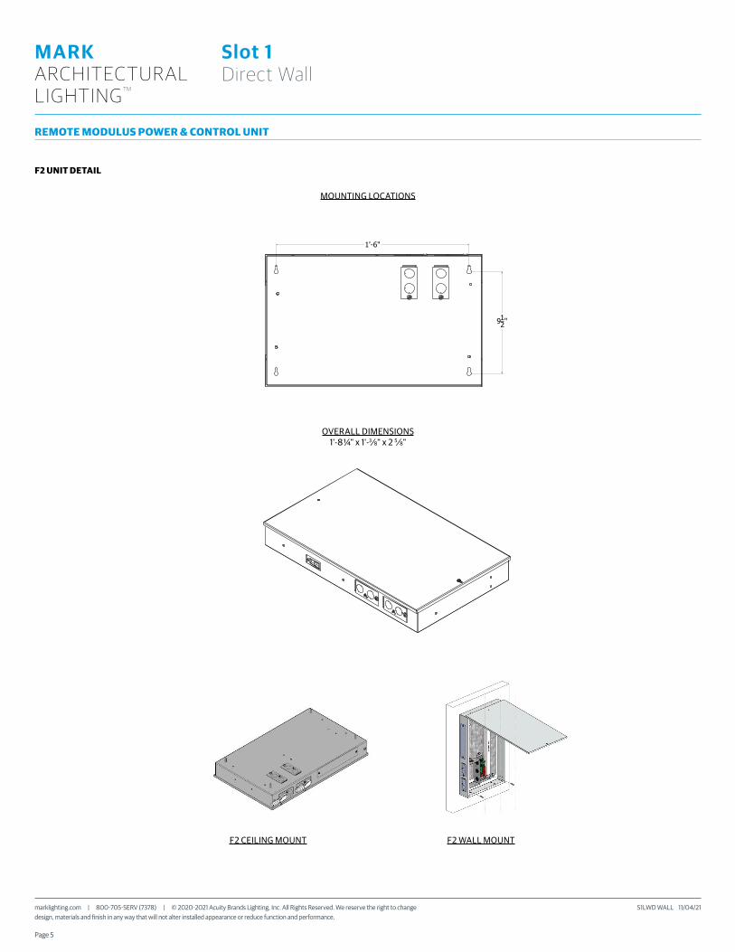
F2 UNIT DETAIL
1'-6"
912"
MOUNTING LOCATIONS OVERALL DIMENSIONS1'-8 1/4" X 1'- 3/8" X 2 5/8"
MOUNTING LOCATIONS
OVERALL DIMENSIONS1'-8 ¼" x 1'-3⁄8" x 2 5⁄8"
F2 CEILING MOUNT F2 WALL MOUNT

Page 6
S1LWD WALL 11/04/21 marklighting.com | 800-705-SERV (7378) | © 2020-2021 Acuity Brands Lighting, Inc. All Rights Reserved. We reserve the right to change design, materials and finish in any way that will not alter installed appearance or reduce function and performance.
MARK ARCHITECTURALLIGHTING TM
Slot 1 Direct Wall
LINEAR PLAN
Mark Lighting offers the ability to provide a continuous run plan to suit your requirements by optionally offering three different methods of configuration.
LLP- Linear Longest PossibleIn this configuration, the longest length available is optimized, resulting in the fewest segments and mounting locations. Caution should be used where balanced appearance is a concern. Example: 20 FT run would have 2, 8 FT segments and 1, 4 FT segment at the end of the run.
LCB- Linear Center Balanced:This configuration incorporates the longest center segment(s) along with any additional lengths required to fill the run length, added to the run ends. Example: 16 FT run would have 2, 4 FT segments (one at each end) and 1, 8 FT segment in the center.
LSL- Linear Same Length:In this configuration, each segment is the same length and is standardized based on the longest length available and is the only option provided. Because it is dependent on one segment length and there are mathematical limitations on what overall row lengths can be achieved. Example: 20 FT row would be achieved with 5, 4 FT long segments equaling 20 FT (nominal).
8 FT 8 FT 4FTLLP
4 FT 8 FT 4FTLCB
4FT 4FT 4FT 4FT 4FTLSL
"A"
"B"
"C""C"
ORDERED LENGTH
INDIVIDUAL FIXTURES
2FT
3FT
4FT
"A" O.A.L.
2'- 3/8"
"B" O.C.
1'- 4"
5FT
6FT
7FT
8FT
3'- 3/8"
4'- 3/8"
5'- 3/8"
6'- 3/8"
7'- 3/8"
8'- 3/8"
1'- 4"
2'- 8"
4'
5'- 4"
5'- 4"
6'- 8"
APPROX. WEIGHT
3LB
5LB
7LB
8LB
10LB
11LB
13LB
"C" FROM END
4 3/16"
10 3/16"
8 3/16"
6 3/16"
4 3/16"
10 3/16"
8 3/16"
"A-1""B" "B" "B"
"A-2" "A-1"
"C" "D" "D" "C"
ORDERED LENGTH
RUN LAYOUT
4FT
5FT
6FT
"A-1" O.A.L.
4'- 3/16"
"B" MOUNT POINT "C" FROM END"A-2" O.A.L.
4'-0"
5'-0"
6'-0"
7FT
8FT
7'-0"
8'-0"
5'- 3/16"
6'- 3/16"
7'- 3/16"
8'- 3/16"
APPROX. WEIGHT
7LB
8LB
10LB
11LB
13LB
"D"
1'-4"
1'
8"
1'-8"
1'-4"
2'- 8"
4'
5'- 4"
5'- 4"
6'- 8"
8 3/16"
6 3/16"
4 3/16"
10 3/16"
8 3/16"
Left (L) Intermediate (I) Right (R)
Total Run LengthThis system is not modular. Runs longer that 8FT will be automatically configured with left, intermediate and right sections, based on how you specify the TOTAL RUN LENGTH and MAXIMUM SECTION LENGTH parameters in the ordering information. Always order the total run length, not the individual sections.
Example: This run must be ordered as 1pc “S1LWD LLP 32FT MSL8...”
Example: If you order as 4pcs “S1LWD LLP 8FT MSL8... you will receive these INDIVIDUAL sections that cannot be joined together
Maximum Section LengthThe run will be broken out using as many sections at the chosen MSL length as possible. Shorter sections will then complete the desired run length.
Examples: S1LWD LLP 21FT MSL5... = 5FT / 4FT / 4FT / 4FT / 4FT S1LWD LLP 21FT MSL6... = 6FT / 6FT / 5FT / 4FT S1LWD LLP 21FT MSL7... = 7FT / 7FT / 7FT S1LWD LLP 21FT MSL8... = 8FT / 8FT / 5FT
This system is not modular. Runs longer that 8FT will be automatically configured with Starter, Middle and Ender sections, based on how you specify the TOTAL RUN LENGTH and MAXIMUM SECTION LENGTH parameters in the ordering information. Always order the total run length, not the individual sections
32FT
8FT 8FT 8FT 8FT
Example: This run must be ordered as 1pc "S1LID LLP 32FT MSL8..."
TOTAL RUN LENGTH
The run will be broken out using as many sections at the chosen MSL length as possible. Shorter sections will then complete the desired run length.
Examples: S1LID LLP 21FT MSL5... = 5FT / 4FT / 4FT / 4FT / 4FTS1LID LLP 21FT MSL6... = 6FT / 6FT / 5FT / 4FTS1LID LLP 21FT MSL7... = 7FT / 7FT / 7FTS1LID LLP 21FT MSL8... = 8FT / 8FT / 5FT
8FT
MAXIMUM SECTION LENGTH
8FT 8FT 8FT
Example: If you order as 4pcs "S1LID LLP 8FT MSL8... you will receive these INDIVIDUAL sections that cannot be joined together

Page 7
S1LWD WALL 11/04/21 marklighting.com | 800-705-SERV (7378) | © 2020-2021 Acuity Brands Lighting, Inc. All Rights Reserved. We reserve the right to change design, materials and finish in any way that will not alter installed appearance or reduce function and performance.
MARK ARCHITECTURALLIGHTING TM
Slot 1 Direct Wall
INTELLIGENT LUMINAIRE CHARTS
CONTROLSRemote sensors can be paired with NLIGHT options to control your runs.
Choose nomenclature from these columns
Driv
er C
onfig
urat
ions
Minimum Dimming Level Control Input Driver Dimming
Range Notes
MIN1 DALI eldoLED DCDC DUALdrive 100 to 1% Logarithmic Dimming, DALI controls and power supply supplied by others
MIN1 ZT eldoLED DCDC DUALdrive 100 to 1% Linear Dimming, supplied with leads for two independent zones of 0-10V
MIN1 NLIGHT eldoLED DCDC DUALdrive 100 to 1% Logarithmic Dimming, nIO EZDCA 16Z in head unit
MIN1 NLTAIR2 eldoLED DCDC DUALdrive 100 to 1% Logarithmic Dimming, rIO EZDL in head unit with external antenna
DARK DALI eldoLED DCDC DUALdrive 100 to 0.1% Logarithmic Dimming, DALI controls and power supply supplied by others
DARK ZT eldoLED DCDC DUALdrive 100 to 0.1% Linear Dimming, supplied with leads for two independent zones of 0-10V
DARK NLIGHT eldoLED DCDC DUALdrive 100 to 0.1% Logarithmic Dimming, nIO EZDCA 16Z in head unit
DARK NLTAIR2 eldoLED DCDC DUALdrive 100 to 0.1% Logarithmic Dimming, rIO EZDL in head unit with external antenna
Cont
rol +
Sen
sor
Confi
gura
tion Control Sensor Sensor Notes
NLIGHT + VPIR15 ADC = VERTEX 15F EZ ADC VLP Only 5 sensors per Modulus driver unit. Zoning reconfigurable via Sensorview software.
External sensor and power packs
Control Input
NLIGHT (Cat-5E)ZT (0-10V wires)NLTAIR2 (wireless)DALI
Class 1 DC Power
Class 1 AC Input
Modulus Power & Control
SLOT1 Luminaire
Sensorview Software(only required for rezoning)CAT-5eClass 1 DC Power
Class 1 AC Input
Slot 1 Head Unitwith NLIGHT or
NLT control
Slot 1 Luminaire withIntegral VERTEX Sensor
FOR INTERNAL CONTROLS

Page 8
S1LWD WALL 11/04/21 marklighting.com | 800-705-SERV (7378) | © 2020-2021 Acuity Brands Lighting, Inc. All Rights Reserved. We reserve the right to change design, materials and finish in any way that will not alter installed appearance or reduce function and performance.
MARK ARCHITECTURALLIGHTING TM
Slot 1 Direct Wall
EMERGENCY OPTIONS
S1LWDEC circuits default to the right side 4’ section, of an 8’ fixture (EC/R) and the complete section of a 4’ fixture (EC/L). Single EC circuit defaults to the last 4’ of the run. Two EC circuits default to the last 4’ of the run and the first 4’ of the run. Additional circuits will be added from the end of the run using the last 4’ of an 8’ fixture or complete 4’ fixtures.
100% 0%0% 100%100%0% 100%
EC/L
Modulus EC / UNIT
S1LWD LLP...4EC
Default locations for multiple ECs.
EC/REC/RS1LWDL EC/R
S1LWD LLP...4EC Default locations for multiple ECs.
EXAMPLES *Note that this example is for suspended, but the layouts apply to the wall mount product.
Head unit
E35I
NV
IIS-35-HE Normal input power
S1LWD U8 E35INV
100% output 100% output100% output100% output
10 FC (min) in designed application
10% output 10% output10% output10% output
1 FC (min) in designed application
Test Switch
Head unitIIS-35-HE Normal input power
Test Switch
Norm
al p
ower
on
Norm
al p
ower
on
Emergency System Diagrams
100% output 100% output100% output100% output
0% output0% output0% output
B.
D.
Head unit
EmergencyPanel with UL 1008
Transfer Switch
Normal power
Backup power
100% output
Head unit
EmergencyPanel with UL 1008
Transfer Switch
Normal powerNormal power (sense only)
Emergency panel power
Normal power (sense only)
Emergency panel power
Backup powerModulus output
Modulus output
Modulus output
Modulus output
EC
Test Switch
Test Switch
S1LWD U8 E35INV S1LWD U8 E35INV S1LWD U8 E35INV
S1LWD U8 E35INV S1LWD U8 E35INV S1LWD U8 E35INV S1LWD U8 E35INV
S1LWD U8...EC/N S1LWD U8...EC/N S1LWD U8...EC/N S1LWD U8...EC/N
S1LWD U8...EC/N S1LWD U8...EC/N S1LWD U8...EC/N S1LWD U8...EC/N
Page 9
S1LWD WALL 11/04/21 marklighting.com | 800-705-SERV (7378) | © 2020-2021 Acuity Brands Lighting, Inc. All Rights Reserved. We reserve the right to change design, materials and finish in any way that will not alter installed appearance or reduce function and performance.
MARK ARCHITECTURALLIGHTING TM
Slot 1 Direct Wall
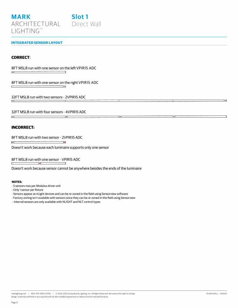
INTEGRATED SENSOR LAYOUT
8FT MSL8 run with one sensor on the left VPIR15 ADC
CORRECT:
32FT MSL8 run with four sensors - 4VPIR15 ADC
8FT MSL8 run with one sensor on the right VPIR15 ADC
32FT MSL8 run with two sensors - 2VPIR15 ADC
8FT MSL8 run with two sensor - 2VPIR15 ADC
Doesn’t work because each luminaire supports only one sensor
Doesn’t work because sensor cannot be anywhere besides the ends of the luminaire
8FT MSL8 run with one sensor - VPIR15 ADC
NOTES:- 5 sensors max per Modulus driver unit- Only 1 sensor per �xture- Sensors appear as nLight devices and can be re-zoned in the �eld using Sensorview software- Factory zoning isn’t available with sensors since they can be re-zoned in the �eld using Sensorview- Internal sensors are only available with NLIGHT and NLT control types
INCORRECT:

Page 10
S1LWD WALL 11/04/21 marklighting.com | 800-705-SERV (7378) | © 2020-2021 Acuity Brands Lighting, Inc. All Rights Reserved. We reserve the right to change design, materials and finish in any way that will not alter installed appearance or reduce function and performance.
MARK ARCHITECTURALLIGHTING TM
Slot 1 Direct Wall
SPECIFICATIONS
HousingNominal 2.3125" x 1.5" extruded aluminum housing
FinishWhite, Black or Silver powdercoat
ReflectorFormed steel with high reflectance white
Distribution/ShieldingWall Graze (WG) and Direct Asymmetric (DAS) are available to provide precides distribution for specific applications. Shielding is available by using a Quiet Ceiling Baffle (not available with specific optics) that aids in hiding the light source from normal view.
LED ComponentsLinear: Nichia®- 757 series LED chips (>80 CRI)
ElectricalLong-life LEDs, coupled with high-efficiency drivers, provide superior quantity and quality of illumination for extended service life. 90% LED lumen maintenance at 60,000 hours (L90/60,000).
Modulus Remote Power and Control SystemRemote power source provides “natural dimming” with smooth, continuous and flicker-free dimming to dark (0.1%). Syncing for controls: 2mA max.
THD: <10%. Insignificant inrush current at 120 and 277VAC. FCC Class A and B tested for EMI and RFI. When NLIGHT or DALI is specified driver will be set for logarithmic dimming curve. If control Input of 0-10V is specified driver will be set for linear dimming curve.
Integrated digital nLight® module enables 4 channel wired networking via Cat-5e, when nLight® is selected. For daylight dimming and / or dual technology detection, see controls page for external sensor options.
Color ConsistencyThe Acuity Brands circuit boards for the linear LED components use a precise binning algorithm which creates a consistent color temperature from board to board. The color a variation of no greater than a 2.5 Step MacAdam (2.5SDCM) along the black body locus from board to board.
DrivereldoLED® driver provides natural dimming with smooth, continuous and flicker-free deep dimming. Supports operation between 120 VAC and 277 VAC, with low inrush current (NEMA 410) and THD < 20%. Meets FCC Title 47 C.F.R. 15 Class A or Class B requirements. Lutron interface module is also available.
Acuity luminaires incorporating eldoLED LED drivers perform within the recommended operating areas for flicker as a function of frequency and modulation (%) outlined in IEEE Standard 1789-2015 (IEEE Recommended Practices for Modulating Current in High-Brightness LEDs for Mitigating Health Risks to Viewers), in typical operating conditions at representative dimming levels.
Certification Tested to UL 2108 standards.
Warranty5-year limited warranty. Complete warranty terms located at: www.acuitybrands.com/support/warranty/terms-and-conditions
Note: Actual performance may differ as a result of end-user environment and application. All values are design or typical values, measured under laboratory conditions at 25 °C. Specifications subject to change without notice.