sm64910 rev 06-14
TRANSCRIPT

Aerospace Group Conveyance Systems Division Carter® Ground Fueling
SM64910 June 2014 Applicable addition manuals: None
Maintenance & Repair Manual
4” Hydrant Coupler with Pressure Control To Mate Hydrants In Accordance With EIEI Bulletin 1584
Model 64910

SM64910 April 2011
2
TABLE OF CONTENTS
Page
TABLE OF CONTENTS .......................................................................................................................................... 2
1.0 Introduction ................................................................................................................................................. 3
2.0 Equipment Description ............................................................................................................................... 3
3.0 Table of Options and Ordering Information ................................................................................................ 3
4.0 Operation .................................................................................................................................................... 5
5.0 Safety Information - Periodic Inspections .................................................................................................. 8
6.0 Trouble Shooting and Minor Repair ......................................................................................................... 11
7.0 Installation ................................................................................................................................................ 15
8.0 Special Tools ............................................................................................................................................ 17
9.0 Disassembly ............................................................................................................................................. 17
10.0 Inspection and Repair .............................................................................................................................. 21
11.0 Reassembly .............................................................................................................................................. 23
12.0 Testing ...................................................................................................................................................... 27
13.0 Storage ..................................................................................................................................................... 30
14.0 Illustrated Parts Catalog ........................................................................................................................... 30
Figure 1 - 64910 Hydrant Coupler & Options ........................................................................................................ 37
Figure 2 - 64910 Lower Coupler Half Assembly 47663 ........................................................................................ 38
Figure 3 – 64910 Pressure Control Elbow Assembly 47220 ................................................................................ 39
Figure 4 - Option 3 Male Half Quick Disconnect Assembly 47226 ....................................................................... 40
Figure 4A – Female Half Quick Disconnect Assembly 47571 to Mate Option 3 ................................................... 40
Figure 4B – Option Z 4 .......................................................................................................................................... 41
Figure 5 - Option 4 Quick Disconnect Assembly ................................................................................................... 42
Figure 5A – Female Half Quick Disconnect Assemblies to Mate Option 4 ........................................................... 42
Figure 7 - Carriage Assembly................................................................................................................................ 43
Figure 9 - Carriage Installation .............................................................................................................................. 43
Figure 10 - Inner Piston Seal Installation .............................................................................................................. 44
Figure 11 - Outer Seal Installation ........................................................................................................................ 45
Figure 12 - Standard Transverse Carrying Handle ............................................................................................... 45
Figure 13 - Option Y Carrying Handle ................................................................................................................... 46

SM64910 April 2011
3
Maintenance, Overhaul & Test Instructions Model 64910 Fuel Pressure Control Coupler
1.0 INTRODUCTION
This manual furnishes instructions for the installation, operation, periodic inspection, trouble shooting, minor repair and complete overhaul of Eaton’s Carter brand Model 64910 fuel pressure control coupler designed to mate with adapters and hydrant valves built in accordance with EI Bulletin 1584.
Maintenance and overhaul of repairable sub-assemblies, including all the various options, are also included.
The last section of this manual contains assembly drawings for identification of replaceable parts and other significant maintenance items referred to in these instructions. References in the text to the assembly drawings for part identification are by item number in the list of material on the drawing.
2.0 EQUIPMENT DESCRIPTION
Model 64910 Fuel Pressure Control Coupler is the latest 4” coupler design and supersedes Model 64900.
It is designed for use with aviation turbine fuels in an operating temperature range of -40° F to 158° F [-40° C to 70° C].
The standard Model 64910 coupler consists of three basic modules; a 47780 dry break coupler lower half, a 47220 fuel pressure control elbow assembly, and various female disconnects, each with a different thread type and size, as explained below.
Model 64910 lower half assembly has been completely redesigned. This new lower half incorporates three (3) detent pins, an internal collar locking device, and collar lifting handles [both “short” (standard) or “tall” (option “T”)], providing improved ergonomics and operational handling during disconnect. Earlier coupler Models 64900 and 60700-1 can be retrofitted to gain these new features by changing only the lower half assembly.
Two additional coupler models that include this new lower half are also available, Model 64912 for digital pressure control systems, and Model 64913, which is electro-hydraulically controlled.
The coupler mates with standard 4-inch adapters and hydrant valves that conform to EI Bulletin 1584. In addition, the 64910 is designed to meet all requirements of EI Bulletin 1584 3rd Edition with regard to the pull away or break away requirements. Test results to show compliance are available upon request.
The outlet of the unit may be equipped with one of two different styles of quick disconnects. Options are available using either an O-ring (five options) or Teflon Seal (four options). Other than the different sealing options, disconnects are similar except for the female pipe thread size and type incorporated in the housing that mates with the hose fitting. The tables in paragraph 3.0 tabulate the various options available with the basic unit.
The lower half coupler provides a quick means to connect to a hydrant or adapter with dry break capability. The coupler will not open unless it is
connected to a valve; it cannot be removed from that valve unless it is in the closed position.
The unit incorporates a pressure operated relief valve that is automatically opened by the coupler when the coupler poppet is closed, to provide a vent to the downstream side of the main piston seat, relieving a hydraulic lock that would otherwise prevent coupler poppet closing. The spring-loaded relief valve also relieves automatically whenever the differential pressure across the closed pressure control piston seat exceeds approximately 220 psi in the inlet to outlet direction.
The pressure control elbow assembly is a direct operated, normally closed, fuel pressure control and shutoff valve. Application of 25-33 psig air pressure (bias) greater than the maximum desired fuel pressure through the air reference connector overrides the piston spring and, opposed by remote sensed fuel pressure, holds the piston in the positions required to maintain the desired regulated pressure at the remote sensed point throughout the ranges of all normal inlet pressure and fuel flow rates. Release of the air reference pressure, normally through a three-way deadman type valve, causes the main piston to close. When downstream flow passages become blocked an increased fuel sense pressure, in excess of the preset limits by 1.5 psi, will counter act the air reference pressure which will then cause the piston to close. This action helps reduce surge characteristics.
A spring-loaded adjustable orifice screw in the deadman air passage restricts air flow in and out of the air piston chamber, which in turn primarily limits the unit’s closing rate.
A restrictor check valve, located in the fuel sense port, that restricts fuel flow out of the inner piston chamber but allows full flow in the piston closed direction, primarily limits the unit-opening rate
The inner piston has two dynamic seals, one to retain the fuel sense pressure and the other to retain the air reference pressure. There is a void between these two seals that is vented to atmosphere. This will prevent fuel contamination of the air control system within the hydrant dispenser. A filter disc protects the ambient vent from aspiration of external contaminants into the unit.
3.0 TABLE OF OPTIONS AND ORDERING INFORMATION

The basic Model 64910 is available with a variety of options to meet specific requirements. The complete coupler part number consists of four parts as noted below. The various options, when compatible, can be combined and listed following the 64910 in Part 1 to achieve a complete unit. For example: 64910BC4L is
a basic unit with a folding handle, product selection, short collar lock lifting handles (standard), external dust cap (standard), ¼” NPT air reference port, 3/8” NPT fuel reference port and a female half quick disconnect with 3" NPT outlet.
The part number of a complete coupler consists of four basic parts as illustrated below.
PART 1 – MODEL NUMBER
64910
PART 4 – Letter describing the outlet thread type & size.
PART 3 – Number describing the male adapter required to mate the desired outlet configuration.
PART 2 – Options B-Y describing various changes to the basic coupler configuration.
PART 2
The following options may be added as Part 2 of the part number as indicated above to order a unit to meet your requirements: OPTION LETTER DESCRIPTION
OPTION LETTER DESCRIPTION
A *Changes lugs to EI/EI 1584, 2nd edition H Adds 3/8” FNPT adapter fittings to both air & fuel sense ports.
B Adds folding handle (41731) J Adds 3/8” hose barb fittings to both air & fuel ports.
C Adds product selection (41802) R Adds 90° elbow ¼” FNPT for hose connection to air operated hydrant valve.
D Adds lock wire to flange & joint fasteners on inlet & outlet of elbow.
W Adds carriage assembly (60532C).
E Adds 61498 air/fuel sense plug per EI 1584 T Y
Tall collar lock lifting handles (47437) Adds outlet port carrying handle (47224)
F Adds hose barb fittings to air (1/4”) & fuel sense (3/8”) ports
* Refer to Product News Bulletin PN649001020 for a complete description of this change before ordering. Changes lugs to part number 200688 (2nd edition) in lieu of part number 221860 (3rd edition)
PART 3
One of the numbers below must be included, as Part 3, to specify the type of outlet configuration desired. The coupler may be ordered with the outlet terminating in an adapter half only if desired. In this case leave Part 4 blank. If a female half is desired, Part 4 must be completed.
OPTION LETTER
DESCRIPTION
OPTION LETTER
DESCRIPTION
3 Specifies adapter to mate older style O-ring type seal with part 4 QD.
4 Specifies adapter to mate newer Teflon Seal (5A-9) type QD in part 4.
PART 4
One of the following letters must be included, as Part 4, to specify the outlet thread and size:
OPTION LETTER
DESCRIPTION
OPTION LETTER
DESCRIPTION
L Adds female inlet. Thread – 3" NPT P Adds female inlet. Thread – 4" NPT
M Adds female inlet. Thread – 3” BSPP R Adds female inlet. Thread – 4” 8 NPSC (use with option 3 of part 3 above only).

SM64910 April 2011
5
N Adds female inlet. Thread – 4” BSPP Z Adds female inlet. Thread – 4” BSPP, with cast handle
Examples: 64910BF4P – 64910 Coupler with folding handle, short collar lock lifting handles (standard), hose barb fittings in air/fuel ports and 4” QD with Teflon Seal (5A-9).
4.0 OPERATION
Operation consists of connecting the coupler to the hydrant pit valve adapter, applying air pressure to the unit by actuation of the system deadman control to open the pressure control valve, flowing fuel through the open coupler and valve for the required period, closing the pressure control valve by releasing the deadman control, and disconnecting the coupler from the hydrant adapter. Operation may also include reverse flow through the unit for defueling purposes.
4.1 Coupler Connection
A. Remove the dust cap assembly and place the face of the coupler assembly over the pit valve adapter. Use one hand to overcome hose weight bending forces so the coupler face is centered and square to the adapter face. Normally the weight of the coupler, when properly aligned, will cause the three (3) spring-loaded detent pins to be depressed by the adapter flange, permitting the collar to drop, locking the 16 lugs to the adapter. If the unit incorporates Option C, Product Selection, it may be necessary to rotate the collar before it can drop. This can be done easily by rotating only the collar. It is not necessary to rotate the coupler body and the servicer pickup hose.
B. With the collar dropped or extended, the two mating poppets may be opened by simply rotating the coupler poppet operating handle in the open direction as permanently marked on the handle.
Note: It should be understood that the poppet operating linkage is over center with the poppet operating handle in either the full closed or full open position. This feature is required to prevent internal pressure from opening the poppet when the mechanism is in the closed position; and to prevent an external force from closing the mechanism when it is fully opened. Consequently, rotating the poppet operating handle to open, initially causes, the poppet to retract slightly into the coupling before moving in the poppet open direction. Further, the poppet operating handle cannot be operated in the open direction if the collar is not extended, because of a physical interference between the handle and the collar. At the same time, the collar cannot be extended, unless the spring-loaded detent pins are depressed, normally by contacting the face of the pit valve adapter. Once extended, the collar cannot be retracted if the poppet handle is in other than the fully closed position and if the Collar Stop Assembly is not depressed. Together, these features provide safety interlocks preventing a potentially hazardous or undesirable spill, by preventing the accidental opening of the unit while coupler is disconnected, or, accidental disconnection with the poppet in the open position.
C. If the adapter is pressurized by hydrant pressure at the time of poppet opening, resistance will be felt when the coupler poppet contacts the adapter poppet. The resistance will be proportional
to the hydrant pressure. The opening resistance force of an Eaton Carter brand hydrant valve is composed of two factors, poppet spring force plus any force created by fuel pressure in the hydrant. The normal spring force is approximately 20 pounds and the pressure force is equal to over 125 pounds for each 10-psi present. In addition to the forces attributed to the hydrant, there are forces presented by the coupler itself. The initial movement of the operating handle to get it over center is resisted by a stack of wave washer springs on the nose seal plus seal friction. Under even severe weather conditions, the coupler can be opened by the application of less than 30 pounds force applied to the handle. Since the hydrant pit valve adapter poppet is equipped with a pressure equalizing valve, maintain a steady, moderate force on the handle in the open direction, sufficient to hold open the adapter pressure equalizing valve until the pressure has equalized across the poppets. Then the handle can be easily moved to the full open position, permitting full communication between the hydrant adapter and the fuel pressure control valve.
It should be noted that the early release of the EI Bulletin 1584 did not cover the need for a pressure equalizing valve. This resulted in the hydrant valve manufacturers having different dimensions for the location of the operating tip of the valve. There is some incompatibility between the various older hydrants and couplers if they are intermixed. The result can be either one of considerable leakage during hookup or non-function of the equalizing valve making it very difficult to achieve connection.
Note: The time required for pressure equalizing to occur is contingent on the unfilled downstream volume, the capacity of the adapter pressure equalizing valve, and the hydrant pressure. It is also affected by the amount of leakage through the lower hydrant piston seals. If it is consistently difficult to open the coupler the hydrant valve maybe “hot” and it should be overhauled.
4.2 Fuel Pressure Control Valve Operation
4.2.1 Discussion
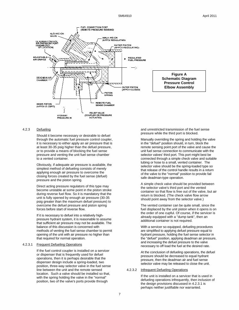
Figure A is a schematic diagram of the Fuel Pressure Control Elbow Assembly Module (unit) on which the major functional elements are illustrated and labeled. While Figure A is a schematic, the general shapes of the parts have been retained as much as possible to permit a better understanding of the actual hardware.
The inner and outer piston assembly has been split on Figure A so that the lower half illustrates the position of the pistons when the unit is closed, either because deadman air pressure is not applied or because the fuel sense pressure and the piston spring have overpowered the air pressure, and other opening forces that might be present. The upper half of the piston assembly on Figure A illustrates

SM64910 April 2011
6
the position of the pistons when the unit is partly open and regulating fuel pressure.
By referring to Figure A while reading this section it should assist you in achieving a thorough understanding of the unit’s operation.
With the coupler engaged and the poppets open, hydrant pressure is available at the unit's outer piston seat. The unit's piston is held normally closed by piston spring force until air pressure is applied, usually through a 3-way normally closed valve known as a deadman valve (since release of the valve's handle blocks air pressure supply to, and vents air from, the unit).
In common with pilot operated pressure control valves, this direct operated unit incorporates a regulated air pressure over fuel pressure bias. In this direct operated unit the bias is provided by the main piston spring, which is not adjustable.
The piston spring design is such that the spring bias force equals approximately 25-psig air over fuel pressure when the unit piston is near the seat, and as much as 33-psig air over fuel pressure when the piston is full open. These numbers cannot be absolute for all possible installations since there is a small area imbalance in the piston open direction caused by slight differences in sealing diameters of the outer piston's dynamic seal and its seat. With 140-psig hydrant pressure applied, the imbalance translates into 5-psig less air pressure required than pure force calculations imply.
So it is necessary to adjust the deadman air pressure applied to the valve to achieve the desired delivery pressure.
At any rate, if the regulated pressure at the remote sensed delivery point is considered to be too high, or too low, it is a simple matter to either increase, or decrease, the air pressure to achieve the desired delivery pressure. Of course, if the delivery pressure is low because inlet pressure is insufficient to overcome system resistance at high flow rates, then increasing the air pressure will not increase the delivery pressure (since the unit is already full open under those conditions) and will result in higher downstream pressure during normal shutoff. It should also be understood that using very high air pressure to compensate for system pressure losses will result in high shutoff and surge arrest pressures.
4.2.2 Refueling
Considering the previous discussion concerning bias, assuming that the unit has been filled and properly bled of air (see paragraph 7.5) and that the deadman air pressure is preset at the desired value, then the only action required to operate the automatic fuel pressure control valve (unit) is to
squeeze the deadman valve to apply the air pressure to open the piston.
The main piston opening rate is limited by a restrictor check valve in the fuel sense passages that restricts displacement of fuel from the fuel control chamber as the chamber's volume decreases when the piston opens.
The piston continues to open until the pressure at the remote sensing point, transmitted back through the fuel sense line, reaches the range that is equal to the applied air pressure, less the bias force of the main piston spring. At this flow rate, the main piston modulates to maintain equilibrium across the inner piston and provides automatic pressure control by varying the effective flow area at the outer piston.
As the receiver aircraft tanks progressively fill and shut off, the flow reductions in each instance cause the pressure to increase at the remote sensing point. These pressure increases are transmitted back though the fuel sense hose. The previously mentioned restrictor check valve is lightly spring-loaded, in that it begins to open when the fuel sense line pressure is approximately 1.5 psig greater than the inner fuel piston chamber pressure, creating a variable orifice in parallel with the very small orifice that restricts control fuel flow in the reverse direction. The increase in fuel chamber pressure causes the piston to move in the closed direction, reducing the outlet pressure, until the fuel pressure transmitted back through the fuel sense line has established a new force equilibrium condition, about which the piston modulates until the next receiver aircraft tank fills and shuts off.
When the last receiver aircraft tank has shut off, the conditions described above cause the unit piston to fully close and block hydrant pressure, preventing high pressures from reaching the aircraft manifolds as well as the servicer delivery equipment.
The real response inherent in a direct acting regulator combined with the essentially free flow of control fuel into the remote fuel sense chamber makes the unit an effective automatic surge control device when fueling aircraft with fast closing (1-2 seconds) shutoff valves.
Releasing the deadman valve at any time will cause the unit to close. The piston closing rate in this mode of operation is a function of the air passage orifice, the air hose volume, and any restrictions in the deadman valve. (The fuel restrictor check valve does not significantly affect closing rate, since it easily opens to allow fuel to enter the fuel sense chamber in this closing mode.) The bias force supplied by the piston spring causes the unit piston to be fully closed by the time the air pressure on the air side of the unit inner piston has decayed to about 20 psig.
SM64910 April 2011
7
4.2.3 Defueling
Should it become necessary or desirable to defuel through the automatic fuel pressure control coupler, it is necessary to either apply an air pressure that is at least 30-35 psig higher than the defuel pressure, or to provide a means of blocking the fuel sense pressure and venting the unit fuel sense chamber to a vented container.
Obviously, if adequate air pressure is available, the simplest method of defueling consists of merely applying enough air pressure to overcome the closing forces created by the fuel sense (defuel) pressure and the piston spring.
Direct acting pressure regulators of this type may become unstable at some point in the piston stroke during reverse fuel flow. So it is mandatory that the unit is fully opened by enough air pressure (30-35 psig greater than the maximum defuel pressure) to overcome the defuel pressure and piston spring forces before start of reverse flow.
If it is necessary to defuel into a relatively high-pressure hydrant system, it is reasonable to assume that sufficient air pressure may not be available. The balance of this discussion is concerned with methods of venting the fuel sense chamber to permit opening of the unit with air pressure no higher than that required for normal operation.
4.2.3.1 Frequent Defueling Operations
If the fuel control coupler is installed on a servicer or dispenser that is frequently used for defuel operations, then it is perhaps desirable that the dispenser design include a spring-loaded, two position, three-way selector valve in the fuel sense line between the unit and the remote sensed location. Such a valve should be installed so that, with the spring holding the valve in the "normal" position, two of the valve's ports provide through
and unrestricted transmission of the fuel sense pressure while the third port is blocked.
Manually overriding the spring and holding the valve in the "defuel" position should, in turn, block the remote sensing point port of the valve and cause the unit fuel sense connection to communicate with the selector valves' third port. This port might best be connected through a simple check valve and suitable tubing or hose to a small, vented container. The selector valve should be the spring-loaded type so that release of the control handle results in a return of the valve to the "normal" position to provide fail safe deadman-type operation.
A simple check valve should be provided between the selector valve's third port and the vented container so that flow is free out of the valve, but air return is blocked. (The check valve flow arrow should point away from the selector valve.)
The vented container can be quite small, since the fuel displaced by the unit piston when it opens is on the order of one cupful. Of course, if the servicer is already equipped with a "dump tank", then an additional container is not required.
With a servicer so equipped, defueling procedures are simplified to applying defuel pressure equal to hydrant pressure, holding the fuel sense selector in the "defuel" position, applying deadman air pressure, and increasing the defuel pressure to the valve necessary to off load the fuel at the desired rate.
At the conclusion of defueling operations, the defuel pressure should be decreased to equal hydrant pressure, then the deadman air and fuel sense selector valve may be released to close the unit.
4.2.3.2 Infrequent Defueling Operations
If the unit is installed on a servicer that is used in defueling operations infrequently, then inclusion of the design provisions discussed in 4.2.3.1 is perhaps neither justifiable nor warranted.
Figure A Schematic Diagram
Pressure Control Elbow Assembly

SM64910 April 2011
8
In this case, it will be necessary to disconnect the fuel sense hose at the remote sense point, and plug or cap the port at the remote sense location. The disconnected hose must be left open to atmosphere while the unit is opened and closed during the off loading operation.
It is also necessary to refill and bleed air from the fuel sense hose and inner piston fuel chamber when the fuel sense hose is reconnected following the defuel on/off loading operations.
4.3 Coupler Disconnection
Coupler disconnection is essentially the reverse of connection.
Proceed as follows:
A. First, the poppet must be closed by rotating the poppet handle in the direction marked closed. During the final portion of handle closing travel, a resistance will be felt as the coupler poppet enters the seal and must displace the liquid trapped within the coupler and unit.
B. Maintain a moderate steady force in the closed direction to permit the coupler poppet shaft to open the relief valve in the unit and vent some of the trapped liquid downstream of the unit outer piston seat, permitting the poppets to close.
C. With the poppet closed, the mating seal between the coupler and the adapter is broken, and a poppet leak check may be accomplished.
D. Separation is achieved by using one hand on each collar interlock handle and lifting the collar. Then lift the coupler off the adapter. The spring-loaded detent pins will extend, locking the collar in the retracted position. With the collar interlock retracted, a physical interference between the collar and the handle prevents accidental opening of the coupler poppet.
E. Following reinstallation of the dust cap, the operational cycle is complete and the unit may be returned to its normal stowage location.
5.0 SAFETY INFORMATION - PERIODIC INSPECTIONS
The equipment described herein is designed for safe, convenient, and reliable operation under normal operating conditions. However, the more exposed parts are the greater possibility of damage, and wear over time can result in unreliable or unsafe operation if not detected or corrected. Consequently, it is considered mandatory that a brief safety inspection is accomplished periodically. The frequency of this inspection can vary depending upon the utilization; however, under no circumstances should the frequency be less than once a month. A more thorough periodic inspection should be accomplished at least once a year. Both inspections are discussed in the following paragraphs.
5.1 Interlock
The coupler incorporates an interlock feature that prevents it from being opened unless it is installed onto a hydrant or adapter. The unit may not be removed from the hydrant unless the operating handle has been moved to the closed position and the collar interlock handles have been lifted. The collar interlock mechanism prevents the unit from being blown off the hydrant in the case where the hydrant valve adapter poppet fails to close. During the connection cycle, the interlock is automatically disengaged by the proper alignment of the coupler with the hydrant. During the disconnection cycle, it is necessary to manually lift the collar interlock handles to allow the collar to be moved away from the hydrant valve and complete the cycle. Should a major leakage occur after the operating handle has been closed and before lifting the collar interlock handles, this indicates a failure of the hydrant valve poppet. One should first reopen the coupler poppet and make sure that the hydrant valve pilot has been closed and then close the servicing valve on the hydrant valve before attempting to remove the coupler. If the leakage still is apparent, attempt to close and re-open the coupler to stop the leakage and then shut down the operation of the hydrant system prior to completely
disconnecting the coupler to prevent a possible catastrophic spill.
5.2 Quick Disconnect Retention Method
The female half of the quick disconnect assembly is connected to the male half by means of 24 balls that mate with a groove in the male half and are retained there by a sleeve around the outer diameter of the female half. The sleeve maintains inward pressure on the balls to keep them in the groove of the male half. The sleeve itself is maintained in place by a partially circular wire retaining ring. This ring engages coincidental grooves in the quick disconnect housing and the sleeve. The spreading of the retaining ring allows disengagement of the retaining ring from the sleeve groove and, therefore, movement of the sleeve away from the balls. A retainer plate is used to cover the retaining ring to prevent all but intentional spreading. The coupler should never be operated without the installation of this plate. A secondary locking ring is also provided to prevent the sleeve from moving away from the coupler unless it is intentional.
5.3 Carriage Assembly - Option W.
When utilized, the Carriage Assembly incorporates a torsion spring, which can produce potential injury if the unit is not handled properly. Extending and retracting the castors of the unit should be done with care to prevent possible injury.
5.4 Monthly Periodic Inspections
5.4.1 Safety Inspections
Accomplish the following at least once each month: (An experienced operator should be able to accomplish these inspections in 30 to 45 seconds.)
A. While removing the Dust Cap (1-2) inspect the 16 Locking Lugs (2-2 or 2-2AA) to determine if any are missing, broken, bent, abnormally worn, etc. Verify that the 3 Detent Pins (2-22) are extended and prevents collar extension. While holding the

SM64910 April 2011
9
Collar (2-17) retracted, depress 3 Detent Pins (2-22) individually and release them to verify that they return to their extended position. Examine the Collar for excessive wear, cracks, or other damage. Verify that the Collar Interlock Handle assembly (2-23 and 2-24) is operational and not bent.
Reason: Missing, damaged, cracked, and abnormally worn or broken lugs can result in fuel pressure ejecting the coupler off the adapter with the poppet open. A stuck or malfunctioning detent pin can permit collar extension and accidental opening of the coupler poppet with the coupler disengaged from the adapter. The collar interlock assembly prevents gross adapter poppet leakage from raising the collar and blowing the coupler off the adapter.
B. Visually inspect the closed Poppet (2-16) for signs of abnormal positioning. Visually inspect the molded rubber seal (2-8) for cracks and tears.
Reason: Abnormal poppet retraction or extension indicates a compression or tension failure of portions of the internal linkage that could either result in a mid-position jam or complete separation of the linkage and accidental poppet opening. Damage to the molded seal can result in coupler connected external leakage or coupler disconnected poppet leakage.
C. If the unit incorporates Product Selection (Option C), verify that it is properly installed and that the bolt heads do not extend above the adjacent collar surface.
Reason: Improper product selection installation will, at the very least, result in an unnecessary connection delay, and at the worst, permit connection to the wrong product.
D. Inspect the poppet operating handle for bent, worn, broken, or missing pieces on the round cam-like surface. Inspect the adjacent surface of the collar.
Reason: The round portion of the handle locks the collar in the engaged, extended position. Broken, bent, or missing portions of this handle or of the collar may permit accidental collar retraction with the poppets open, which could result in the coupler being ejected from the adapter.
E. If the Carriage Assembly (1-W) is present, Nuts (3-3) and Washers (3-2) are used to attach it to the mating flanges between the lower half coupler and the pressure control elbow. Check torque of these Nuts (3-3) to assure that they are tightened to 90 ± 10 in.-lbs. (104 ± 12 kg-cm). If the Nuts (3-3) are found to be loose, damage to the Elbow (1-1) threaded holes may have occurred and further inspection in accordance with paragraph 5.5 should be carried out.
Reason: Self-explanatory.
F. Visually inspect the female half quick disconnect to verify that the ball retaining sleeve is fully engaged, and that the ring retainer is secured by two lock wired screws so that the two ends of the retainer ring extend through the remaining two holes in the ring retainer. Verify that the lock ring is engaged in the safety groove immediately adjacent to the ball retaining sleeve.
Reason: See WARNING in paragraph 7.1.
G. Visually inspect the air pressure and fuel sense line connections to the unit's connectors for security of installation and damage. Inspect the unit's body for impact damage or depressions that might cause the main piston to hang open.
Reason: Pressure tight air and fuel connections are required for proper function. Unit body depressions or dents may cause the main piston to hang open and prevent a deadman release shutdown.
H. If the Carriage Assembly (1-W) is used, check to assure that the mounting Flange (6-9) of the Carriage Assembly (1-W) is not mounted flush to the flange on the coupler lower half. The carriage assembly designed for the 64910 Coupler has integral spacers to space it the proper distance from the flanges. If the flange is flush with the mating flanges of the coupler, then an incorrect carriage assembly is being used.
5.5 Extended Periodic Inspections
In addition to the safety inspection advocated above, a more extended inspection should be accomplished periodically. Operators should determine frequency based on local conditions.
It will be necessary to provide a container to capture entrapped fuel during the following inspection. The parenthetical numbers are the item numbers in the list of materials in the referenced tables.
A. Refer to paragraph 7.1 for method of separating female half quick disconnect from the automatic fuel pressure control valve. Capture spilled fuel in a suitable container.
B. Inspect female half quick disconnect. Inspect Balls (4A-8), (4B-8), or (5A-8) for chips, flat spots, or excessive wear. Inspect ball retaining Sleeve (4A-6), (4B-6), or (5A-6) for cracks and wear from the Balls. Inspect Housing (4A-5), (4B-5), or (5A-5) for cracks or thread damage.
C. Replace male adapter O-rings (4-5) and (4-6), or (5-5). Inspect ball race Rings (4-2) or (5-2) for brinelling (indenting of the material by the Balls and any other indications of damage). Remove outer ball race Ring (4-2) or (5-2) and measure the smallest wire diameter. Replace the ball race ring if the smallest wire diameter is 0.123 inch (3.12 mm) or less. Reinstall an acceptable ball race Ring (4-2) or (5-2).
D. Conduct the Coupler Lower Half inspection detailed in paragraph 9.4. If the specified Wear Gauge, 61262, is not available then continue with the inspections detailed in paragraphs E and F below as an alternative. The use of the Wear Gauge will give better results.
E. Grasp opposite sides of the Collar (2-17) and depress 3 Detent Pins (2-22) simultaneously. The Collar (2-17) will move to the engaged position, away from the Poppet Operating Handle (2-42 or 1-B). Verify that the 16 Lugs (2-2) or (2-2AA) cannot be depressed back into the collar with the Collar (2-17) extended.

SM64910 April 2011
10
Note: Carter® Ground Fueling tool 1AF 47663 may be used to help depress all three (3) detent pins.
F. Inspect the 16 coupling Lugs (2-2) or (2-2AA) very closely for wear, cracks or damage. If any Lugs are cracked, damaged, missing, or worn locally beyond 0.030 inch (0.76 mm), the unit is unsafe and should be withdrawn from service and completely overhauled. This inspection may be made by comparison with a new Lug.
Press the tip of one Lug (2-2) or (2-2AA) inward until stopped by the Collar (2-17). While holding the Lug inward, rotate the Collar through 90° to determine whether any grooves have been pressed into the Collar by the Lugs during previous misuse. Repeat this process at every forth lug. If such grooves are evident, they will alternately cause the Lug to move out and in when it is pressed against the Collar. If grooves are felt, the coupling is unsafe and should be removed from service and completely overhauled.
Alternately, press each Lug (2-2) or (2-2A) against the Collar (2-17) to determine which lug protrudes the least distance through the body slot. Then, while holding the Lug against the Collar, use a scale to measure the inward distance the lug tip protrudes from the adjacent body inside diameter. If the measured distance is less than 0.15 inch (3.8 mm), the coupling is unsafe and should be removed from service and completely overhauled.
G. Carefully operate the Poppet Operating Handle (2-1 or 1-B) to the open position while capturing trapped fuel in a suitable container. Operation should be smooth and even.
Note: The molded rubber Nose Seal (2-8), which is normally contained either by the Poppet or the pit adapter face, may extend with the Poppet (2-16) contingent on the relative friction between the Poppet and the Nose Seal; and that between the same Nose Seal and the Quad Ring (2-7) and Housing (2-18). Do not be alarmed if the nose seal does come out of the unit. Use the opportunity to inspect the Wave Washer (2-21) for damage. The Wave Washer is designed such that the ends of layers will be forced against the adjoining layers. Some washers have reached the field where the ends move away from the adjoining layers and into the Nose Seal (2-8) or Body (2-18) causing it to move inward until it tends to jam the mechanism. The Wave Washer should be inspected to assure that it is correctly arranged. Refer to Figure B below, for a graphic representation of the correct arrangement. If it is incorrect it can easily be changed by turning it within itself. The Quad Ring (2-7) may also be replaced if it appears scrubbed. Reposition the Wave Washer and install the Quad Ring onto the Nose Seal (2-8) prior to closing the Poppet (2-16).
Figure B – Wave Washer (2-21)
H. Inspect the molded rubber Nose Seal (2-8) for damage, tears, etc. on both the adapter and poppet sealing surfaces.
I. Lift the Collar Interlock Assembly (2-24) and verify that the Collar (2-17) cannot be retracted with the Poppet Operating Handle (2-42 or 1-B) in any position but the full closed position.
J. With the Poppet (2-16) closed and the Collar Interlock Assembly (2-24) lifted, pull the Collar (2-17) to the retracted position while observing that the spring-loaded Detent Pins (2-22) extend and lock the Collar.
K. With the Poppet (2-16) closed, precisely measure the distance between outer surface of the molded seal and the adjacent surface of the coupler body at two places 180° apart. If the average of these two measurements exceeds 0.100 inch (2.54 mm), the internal linkages are excessively worn and the coupler should be withdrawn from service and completely overhauled.
L. Apply 60-psig minimum air pressure to unit connector. The Piston Assembly should open. Maintain air pressure and, using a flashlight, carefully inspect O-ring (3-18). With the air pressure maintained, place a bubble of liquid soap solution over vent port in Housing (3-32) at Filter (3-34) and observe for excessive leakage. A bubble may form with the soap solution. However, if the bubble quickly forms and breaks, the unit should be overhauled and Seal (3-30) and O-ring (3-29) need replacing. Relieve air pressure. Unit piston should close. Using a flashlight, inspect relief valve passage in unit Seal Retainer (3-14) and verify it is clean and not clogged.
M. If the unit contains Option C, Product Selection, inspect for security, effectiveness and damage. Verify that product selector bolt heads are flush to 0.03 inch (0.76 mm) below the adjacent Collar (2-17) surface.
N. Lubricate unit outlet O-ring (4-6) or Teflon Seal (5A-9), as appropriate, with petroleum jelly. Reassemble and safety lock the female half quick disconnect per paragraphs 7.1. F thru I.
O. Check the mating flange on the Elbow (1-1) with the Body (2-18) for damage to the threaded holes or the wall of the Elbow (1-1). Check the wall between the inner diameter of the coupler upper half Elbow (1-1) and the threaded holes. The diameter should be smooth and continuous with no

SM64910 April 2011
11
evidence of bulging or hairline cracks. If the wall is bulged or cracked, the threads are already over
stressed and the part is no longer safe for use. The coupler Elbow (1-1) will have to be replaced.
6.0 TROUBLE SHOOTING AND MINOR REPAIR
General trouble shooting analysis and minor repair actions are as follows:
6.1 Trouble: Collar (2-17) will not drop or extend during engagement.
Probable Cause:
A. Coupler improperly positioned.
B. Product Selection not mated or incorrectly set.
C. Detent Pins (2-22) are not depressed into hole in Body (2-18) properly.
D. Collar (2-17) may be out of round.
Remedy:
A. Use one hand to relieve hose weight while using the other hand to center and square coupler to adapter.
B. Rotate Collar (2-17) until Product Selection mates. If adapter flange incorporates a tab, align strip or arrow on Collar (2-17) with tab. Verify that adapter and coupler Product Selection is intended to mate.
C. Square coupling face to adapter to assure that the Detent Pins (2-22) are depressed. If hole in Body (2-18) in which Detent Pin (2-22) are housed is egg shaped it may be difficult to depress.
D. If Collar (2-17) is out of round then replace Collar.
6.2 Trouble: Poppet Operating Handle (2-42 or 1-B) cannot be moved in open direction.
Probable Cause: Collar (2-17) is not extended allowing physical safety interlock between Poppet Operating Handle (2-42 or 1-B) and Collar (2-17) to prevent movement of the handle (2-42 or 1-B).
Remedy: Fully engage Collar (2-17). See 6.1 above.
6.3 Trouble: Poppet Operating Handle (2-42 or 1-B)
rotates easily for approximately 45º in the open direction before high resistance is felt.
Probable Cause: This is normal if the hydrant valve adapter is pressurized.
Remedy: Continue to apply moderate pressure to the Poppet Operating Handle (2-42 or 1-B) in the poppet open direction until the pressure equalizes and the poppet opens easily.
6.4 Trouble: External leak between Coupler Lower Half (1-5) flange and Pressure Control Elbow Assembly (1-1).
Probable Cause:
A. Nuts (3-3) loose.
B. O-ring (2-36) damaged.
C. Studs (3-1) in Elbow (1-1) loose.
Remedy: Refer to Figures 1 and 2:
A. Tighten Nuts (3-3) to 90 ± 10 inch pounds (104 ± 12 kg-cm) and recheck for leakage. Note: Special torque wrench kit, WL4680 is available to make it easier to reach less accessible screws and nuts.
B. Replace O-ring (2-36) as follows:
1. Use suitable container to capture entrapped fuel. Verify coupler is depressurized. Remove six Nuts (3-3), six Washers (3-2), and Dust Cap (1-2).
2. Carefully separate Pressure Control Elbow Assembly (1-1) from coupling Body (2-18). Remove and discard O-ring (2-36).
3. Lubricate new O-ring (2-36) and carefully place over pilot on Body (2-18).
4. Carefully assemble Elbow Assembly (1-1) to Coupler Lower Half (1-5), reinstalling six Washers (3-2), and six Nuts (3-3). Torque nuts to 90 ± 10 inch pounds (104 ± 12 kg-cm). Install Dust Cap (1-2)
5. Pressure check new O-ring installation at 5 and 150 psig fuel pressure, if possible. If not possible, carefully observe for leakage during next use.
C. Studs (3-1) should be retightened using two nuts on each as jam nuts. Tighten Studs (3-1) to snug. Over tightening can damage the housing. If threads retaining Studs are damaged then the Elbow (1-1) will have to be replaced.
6.5 Trouble: External leak between disconnect halves.
Probable Cause: Damaged O-ring (4-6) or the Teflon Seal (5A-9) in the female half as appropriate.
Remedy: Remove and replace O-ring (4-6) or the Teflon Seal (5A-9) in the female half as appropriate as follows:
A. Use suitable container to capture entrapped fuel. Refer to paragraph 7.1 for correct method of separating disconnect.
B. With the disconnect separated, remove and discard O-ring (4-6). Lubricate with petroleum jelly and carefully install new O-ring (4-6).
C. Reconnect, safety check, and lock wire disconnect assembly per paragraph 7.1.
D. Leak check at 5 and 150-psig fuel pressure if possible. If not, carefully observe joint during next operation.
Note: Excessive wear of the Wire Race (4-2 or 5-2) or Sleeve (4A-6 or 5A-6) can allow the connection to become loose causing leaks and or premature failure of the O-ring (4-6) or Teflon Seal (5A-9). Refer to section 10.4.
6.6 Trouble: Leak at Poppet Operating Handle (2-42 or 1-B).
Probable Cause: O-ring (2-35) damaged, worn or scrubbed.
Remedy:

SM64910 April 2011
12
A. O-ring (2-35) can be replaced without removing the coupling from the hose.
WARNING:
Assure that the hose is not pressurized.
B. With the coupler held over an adequately sized container, depress the Detent Pins (2-22) and extend the Collar (2-17), operate the Poppet Operating Handle (2-42 or 1-B) in the open direction, opening the Poppet (2-16) to drain the coupler. The coupler will hold approximately 2.5 quarts of fuel between the inlet Poppet (2-16) and the Outer Piston (3-11) when closed. If fuel continues to come out beyond that amount discontinue operation until the coupler can be removed from the hose. Leave the poppet (2-16) open to prevent re-pressurization of the coupler. Refer to section 6.18 to repair internal leakage.
C. Remove Bolt (2-33), lock Washer (3-32), and Washer (2-12). Remove poppet operating Handle (2-42 or 1-B), Key (2-3), and outer shaft seal Bearing (2-14). Use a sharp pointed instrument or pin to remove old O-ring (2-35). Lubricate new O-ring (2-35) with petroleum jelly or equivalent. Use clean, lint-free cloth dipped in clean fuel or solvent to clean the sealing surfaces of the Crank Shaft (2-19) and Body (2-18). Carefully install new, lubricated O-ring (2-35) using clean, smooth blunt instrument to seat it properly. Inspect O-ring (2-35) to verify that it is not twisted.
D. Reinstall outer shaft seal Bearing (2-14), Key (2-3), poppet operating Handle (2-42 or 1-B), Washer (2-12), lock Washer (2-32), and Bolt (2-33). Torque the Bolt (2-33) to 90 ± 10 in.-lbs. (104 ± 12 Kg-cm).
E. If possible, connect this coupler to a pressurized adapter and open Poppet (2-16). Observe the Crank Shaft (2-19) for leakage through several poppet opening and closing cycles.
6.7 Trouble: External leakage between unit and adapter or hydrant with unit engaged and Poppet (2-16) open.
Probable Cause:
A. Damaged adapter sealing surface.
B. Damaged Nose Seal (2-8), or Damaged/ worn Quad Ring (2-7), or Missing, damaged, broken, or Ineffectual Wave Washer (2-21).
Remedy
A. Replace or repair hydrant adapter.
B. Disassemble as follows and inspect Nose Seal (2-8) for tears, abrasions, blisters, bond failure, etc. Inspect Quad Ring (2-7) for damage or wear. And inspect the integrity of the Wave Washer (2-21). If any inspected parts are damaged or otherwise defective, remove and replace with new ones.
WARNING:
Assure that the hose is not pressurized.
1. Open Poppet (2-16) by depressing Detent Pins (2-22) and sliding Collar (2-17) forward, then rotate Handle 2-42) or (1-B) to the open position. Drain the unit in an appropriate basin or tank.
2. Remove Screws (2-16D) from Poppet Assembly (2-16) using a torque wrench. The running torque to remove the Screws (2-16D) shall not be less than 6 in.-lbs. (6.9 kg.-cm.). Remove Poppet (2-16C) and O-ring (2-16B). Discard O-ring (2-16B).
3. Grasp Nose Seal (2-8) with fingers and pull it out of the Body (2-18) bore inspect and discard if necessary. Remove and inspect Quad Ring (2-7), discard if necessary. Use opportunity to inspect Wave Washer (2-21) for damage. Inspect the Wave Washer (2-21) in accordance with Figure B, paragraph 5.5G.
4. Use clean, lint-free cloth soaked in clean solvent or fuel to clean out Body (2-18) bore, and Poppet (2-16). Dry O-ring groove in poppet shaft (2-16A).
5. Lubricate new Quad Ring (2-7) with petroleum jelly and assemble it over new Nose Seal (2-8). Ensure that Quad Ring is not twisted.
6. Position Wave Washer (2-21) in Body (2-18) bore. Carefully insert new Nose Seal (2-8) in Body (2-18) bore, ensuring that new Quad Ring (2-7) is not pinched.
7. Assemble new O-ring (2-16B) to the Shaft (2-16A) after lightly lubricating it. Install Poppet (2-16C) to the Shaft (2-16A) and Screws (2-16D). Torque the Screws (2-16D) to 10 ± 1 in.-lbs. (11.5 ± 1 kg-cm). If running torque of Screws (2-16D) is less than 6 in.-lbs. (6.9 kg-cm) replace the Screws with new ones.
8. Close and open Poppet (2-16) several times. Then close Poppet (2-16), lift both Collar Interlocks (2-24) and retract Collar (2-17) to retracted position.
9. If removed reassemble Coupler Lower Half (1-5) to Pressure Control Elbow Assembly (1-1) and conduct coupler functional, proof pressure and leakage tests per paragraphs 12.4 and 12.5.
6.8 Trouble: Leakage past Poppet (2-16) seal with coupler disengaged.
Probable Cause:
A. Damaged Poppet (2-16) sealing surface.
B. Damaged molded rubber on Nose Seal (2-8).
C. Damaged quad ring (2-7).
Remedy:
Isolate problem by reducing pressure in the unit and draining unit, and opening poppet as described in paragraph 6.7.B.1. Inspect Poppet (2-16C) sealing surface and Nose Seal (2-8). Replace damaged component or components per paragraph 6.7 remedy B. Disassemble only to the extent necessary to replace the Poppet (2-16C), Nose Seal (2-8) or quad ring (2-7). Replace Quad Ring (2-7) if Nose Seal (2-8) is replaced.

SM64910 April 2011
13
6.9 Trouble: Excess force required during last portion of poppet closing travel.
Probable Cause:
A. Steady force had not been applied to poppet operating Handle (2-42 or 1-B) long enough to permit relief valve to vent trapped fluid downstream, relieving the hydraulic lock.
B. Pressure trapped downstream of unit.
C. Relief Valve (3-57 through 64) improperly adjusted.
Note: The Relief Valve Assembly has been redesigned as one assembled unit (3-48), and it requires no adjustment. This Relief Valve (3-48) supersedes items 3-57 thru 3-65 found in older units, refer to Figure 3. It is recommended that the upgrade of the relief valve be accomplished at next overhaul of the unit’s elbow. KD64910-9 contains the Relief Valve assembly (3-48).
D. Relief valve passages clogged with foreign matter or unit piston Seal Retainer (3-14) is installed incorrectly so that relief valve passage is blocked.
Remedy:
A. Apply steady moderate force until poppet closes.
B. Vent trapped pressure.
C. Maintain steady force on poppet Handle (2-42 or 1-B) and momentarily actuate deadman valve to relieve hydraulic lock and close poppet to permit coupling disengagement. Then, remove the unit from service for bench correction. Disassemble only to the extent necessary to readjust relief valve or clean clogged passages (see note paragraph 6.9.C). Perform a bench static pressure test of all seals that are broken during disassembly.
6.10 Trouble:
Unit does not open or opens very slowly (several minutes), when deadman air valve is actuated.
Probable Cause:
A. Coupler poppet has not been opened.
B. Deadman air pressure too low to overcome piston spring.
C. Air pressure hose or passages clogged.
D. Air orifice clogged.
E. Clogged orifice in restrictor Check Valve (3-39 through 46).
F. Locked in downstream pressure has unit shut off.
Remedy:
A. Open coupler poppet.
B. Increase deadman air pressure to 60 psi minimum and reset to the desired control pressure as described in section 4.2.1.
C. Loosen air hose connection at unit connector and verify that air pressure is reaching unit. If it is
not, repair hydrant dispenser air control system as required.
D. Refer to Figure 3. Remove Plug (3-35). The orifice is a Screw (3-37) which has an Allen key type head, under which is a Spring (3-38). Use an Allen key to remove the Screw (3-37). Carefully clean out the slot in the thread of the Screw (3-37). Adjust the position of the Screw (3-37) in accordance with the instructions in paragraph 11.5.1.I. If the system uses fuel reference pressure Screw (3-37) and spring (3-38) should be removed and discarded.
Then re-install the Plug (3-35) ensuring the O-ring (3-36) remained in place around plug during removal. Replace O-ring (3-36) if necessary prior to reinstalling Plug (3-35).
CAUTION:
Never operate the unit without orifice Screw (3-37) and Spring (3-38) installed on systems using air reference pressure. Operation without the air orifice Screw (3-37) can result in propagation of destructive pressure surges into the hydrant system when the deadman air valve is released. The unit is direct operated and, without the air orifice Screw (3-37) and Spring (3-38), the closing rate is very fast.
On fuel reference pressure systems the Screw (3-37) and Spring (3-38) should be removed for proper operation.
E. Remove and clean restrictor Check Valve (3-39 through 46) as follows: Refer to Figure 3.
(1) Remove Check Valve Housing (3-41). The Check Valve (3-45) is located under the housing just removed.
(2) Place Check Valve (3-45) in container of clean fuel and agitate to wash out material clogging orifice hole. Examine O-ring (3-44) and replace if damaged.
(3) Reinstall Spring (3-46) and Check Valve (3-45). Examine O-rings (3-42 and 3-43) and replaced if damaged. Lubricate O-rings (3-42 and 3-43) and install Check Valve Housing (3-41). Reactivate fuel sense line. If necessary, fill fuel sense line and passages with fuel and bleed air prior to use.
F. Unit will open when downstream pressure is relieved by initiating flow.
6.11 Trouble:
Closing time is slow.
Probable Cause:
Deadman air valve is restricting release of air, hose diameters are small and/or hose is exceptionally long or kinked. Unit orifice is clogged or out of adjustment.
Remedy:
Open up deadman air valve vent passages, increase hose inside diameter and/or shorten hose, remove kinks. Refer to paragraph 6.10.D for orifice cleaning instructions and paragraph 11.5.1.I for adjustment instructions.
6.12 Trouble:

SM64910 April 2011
14
A. Unit does not close when deadman valve is released following defuel operation.
B. Unit does not regulate during normal refuel operations following a defuel operation, but acts as simple deadman fuel shutoff valve.
Probable Cause:
A. Servicer incorporates defuel selector valve similar to that discussed in paragraph 4.2.3.1 which is stuck in "defuel" position.
B. Fuel sense line not reconnected after defueling per paragraph 4.2.3.2
Remedy:
Reselect "normal" position of selector valve or reconnect and bleed fuel sense hose per paragraph 7.5.
6.13 Trouble:
Unit opens and then abruptly shuts off when deadman air valve is actuated.
Probable Cause:
Downstream system is blocked.
Remedy:
Open nozzle(s) or other valve blocking flow.
6.14 Trouble:
Unit either does not open, or shuts off early during defuel operations.
Probable Cause:
Defuel pressure, transmitted back through the fuel sense line, has caused unit to shut off.
Remedy:
A. Increase air pressure to a value that is at least 30 psi above the maximum defuel pressure.
B. If A is not practical, proceed per 4.2.3 and subparagraphs.
6.15 Trouble:
Regulated pressure is low at high flow rates. Increasing the air pressure does not increase regulated fuel pressure.
Probable Cause:
Hydrant pressure is insufficient to overcome system resistance at high flow rates and regulator is full open.
Remedy: None unless hydrant pressure can be increased or system resistance reduced.
6.16 Trouble:
Desired regulated pressure is achieved, but flow rate is considered low.
Probable Cause:
Aircraft resistance equals regulated pressure at maximum flow rate.
Remedy:
None unless aircraft operator will agree to an increase in regulated pressure.
6.17 Trouble:
Unit will not maintain steady pressure while in operation. This phenomenon is sometimes called surging or hunting. This problem may manifest itself as small pressure variations such as a 10 psig variation that continuously repeats to the most extreme example with the valve opening and closing very rapidly. Unit may also appear to jump open with no other symptoms
Probable Cause:
A. Fuel sense line and/or fuel control passages contain air.
B. Check Valve (3-45) plugged, blocked in the open position or installed incorrectly.
Remedy:
A. Removal of air from the fuel sense lines and fuel control passages of the coupler is very important for the smooth operation of this valve. Fill fuel sense system and bleed air per 7.5.
B. Remove check valve (3-45) per instructions in section 6.10, Remedy E. The check valve (3-45) should be installed according to the image in Figure 3, with the closed end including the small orifice up.
6.18 Trouble:
Excessive internal fuel leakage.
Probable Cause:
A. Inlet pressure is above 200 psi and relief valve is relieving.
B. Deadman air pressure is not completely relieved.
C. Foreign object is holding unit outer piston off seat.
D. Unit seal leakage.
Remedy:
A. Decrease inlet pressure to less than 175 psi.
B. Completely vent deadman air pressure.
C. Remove unit from hose by disconnecting female half quick disconnect per paragraph 7.1, exercising all specified safety provisions. Apply deadman air pressure to fully open Outer Piston (3-11); use pliers or other gripping tool to remove foreign object; and then release deadman air pressure to close unit. Reinstall on hose by connecting female half quick disconnect per paragraph 7.1.
D. Disassemble the unit per the instructions in section 9 sufficiently to examine Outer Piston (3-11), Seal (3-7) and O-ring (3-18). If the cause of the leak is not found then further disassembly to access relief valve (3-48) may be required.
WARNING:
Do not insert fingers into valve while deadman air is holding piston open. Accidental release of deadman air could result in finger amputation or other personal

SM64910 April 2011
15
injury. Always use needle nose pliers or other grasping tool if practicing this remedy.
6.19 Trouble:
Unit closing rates are too fast.
Probable Cause:
Air orifice screw was not installed during overhaul.
Remedy:
Install air Orifice Screw (3-37) and Spring (3-38) using procedure of paragraph 6.10, remedy D. Observe CAUTION in paragraph 6.10, remedy D.
6.20 Trouble:
Coupler poppet linkage does not cause relief valve to relieve hydraulic lock and vent trapped fluid downstream of closed unit piston seat.
Probable Cause:
Relief Valve (3-57 through 64) is not correctly adjusted.
Note: The Relief Valve Assembly has been redesigned as one assembled unit (3-48), and it
requires no adjustment. This Relief Valve (3-48) supersedes items 3-57 thru 3-64 found in older units, refer to Figure 3. It is recommended that the upgrade of the relief valve be accomplished at next overhaul of the unit’s elbow. KD64910-9 contains the Relief Valve assembly (3-48).
Remedies:
Install Upgrade Relief Valve (3-48). Refer to KD64910-9.
6.21 Trouble:
Collar (2-17) will not move to the stowed position or is difficult to move.
Probably Cause:
The Detent Pins (2-22) are worn on the outer diameter on the spring end of the pin.
Remedies:
A short-term remedy is to rotate the Pin (2-22). A more positive remedy is to replace it.
7.0 INSTALLATION
Installation of the Coupler consists of connecting the outlet to the pickup hose and connecting the deadman air and fuel sense hoses to the unit connector hose fittings. Proceed as follows:
7.1 Pickup Hose Connection
The installation of the 4-inch coupler to the hose is contingent of the optional outlet arrangement incorporated in the specific unit. The Pressure Control Elbow Assembly (1-1) with the appropriate option 3 or 4 male half quick disconnect will connect to any of the five with option 3, 4 with option 4 various sized outlet threaded female half quick disconnects. A proper pipe thread lubricant/sealant should be used when tightening the female half quick disconnect to the hose thread.
A. Remove the two screws that secure the retainer and remove the retainer. Spread the two ends of the lock ring apart and move it to the groove farthest from the ball retaining sleeve.
B. Grasp outside diameter of the ball retaining sleeve with the fingers while using the thumbs to spread the ends of the retainer ring. Slide ball retaining sleeve back until stopped by the lock ring. This action allows the 24 balls to disengage from the mating groove in the option 3 or option 4 male adapter. The two parts may now be separated. Note: The O-ring used on Option 3 to seal the joint between the two halves will provide considerable resistance to separation. The Teflon Seal (5A-9) used on Option 4 will separate easier. Axial force and twisting of the two halves in opposite directions will aid in this operation.
C. Inspect the hose fitting male threads for damage and clean to remove all contamination including old thread tape and or sealants. Clean and repair threads as necessary. Apply anti-seize compound. For Options M or N (BSPP threads) install a proper sized gasket (not furnished by Eaton)
in the proper position. Use the wrench flats on the female Housing (4A-5) or (5A-5) to tighten the female half to the hose fitting. The hose coupling should also be gripped only by the wrench flats.
D. Reconnect, safety lock, and lock wire the female half quick disconnect to the Pressure Control Elbow Assembly (1-1) as appropriate using the following steps:
WARNING:
Improper (or omission of) safety locking and lock wiring of the female half quick disconnect can result in accidental separation of the quick disconnect at high pressures and/or flow rates, resulting in a potentially unsafe and undesirable product spill that could result in personal injury.
E. Assure that O-ring (4-6) or Teflon Seal (5A-9) in the female half, as appropriate, is lubricated with petroleum jelly. Install female half quick disconnect/ hose assembly on to the coupler male adapter. Some twisting may be required to fully seat the two halves.
F. Press forward (away from hose) on ball retainer sleeve while spreading retainer ring with thumbs until sleeve fully captures the balls Release the ends of retainer ring to allow it to snap into the housing groove.
G. Install ring retainer on the female half so that two of its holes capture the ends of the retainer ring while the other two holes line up with the threaded holes in sleeve. Fasten ring retainer on the female half with two screws. Before lock wiring the two screws together, grasp sleeve at two places, without touching retainer ring, and attempt to move sleeve to the disengaged position.

SM64910 April 2011
16
CAUTION:
If sleeve can be moved toward the disengaged position, or can be partially cocked, the female half quick disconnect is unsafe for use and should be withdrawn from service until the cause is found and corrected.
H. One probable cause is mishandling that has resulted in permanent deformation of the tips of Retainer Ring (4A-7) or (5A-7) which has bent them toward each other. If bent sufficiently, then the installation of the Ring Retainer (4A-4) or (5A-4) will hold Retainer Ring (4A-7) or (5A-7) in the spread position so it is not fully engaged in the housing groove.
I. Be sure and move Lock Ring (4A-1) or (5A-1) to safety groove nearest Sleeve (4A-6) or (5A-6). Verify that Lock Ring (4A-1) or (5A-1) is fully engaged in safety groove.
WARNING:
Omission, or loss, of Ring Retainer (4A-4) or (5A-4) can result in accidental separation of the quick disconnect under high flow conditions. Under no condition should the disconnect be used without the Ring Retainer (4A-4) or (5A-4) locking the end of the Retainer Ring (4A-7) or (5A-7) and the Screws (4A-2) or (5A-2), secured.
7.2 Deadman Air and Fuel Sense Connections
Please be advised to prevent damage to the housing (3-32) all ports on the 64910 hydrant coupler include straight threads that require adapters with O-rings to seal. NPT connections should be made to those adapters.
Connect the deadman air hose to the ¼” straight thread air reference port with the standard female NPT port adapters, option H port adapters or to the option F or J hose barbs. Connect the fuel sense hose to the port marked Fuel in a like manner. If desired, where air operated hydrant valves are utilized, connect a hose to the side port on the coupler or to option R the 90° elbow to connect to the air pilot on the hydrant.
7.3 Product Selector Set
If unit contains Option C, Product Selection, verify that set is correctly positioned for desired product. If it is not, reposition the Bolts (1-C) and verify that all bolt heads are flush to 0.03 inch (0.76 mm) below the adjacent Collar (2-17) surface.
7.4 Installation Inspection
Verify security of installation, reinstallation and lock wiring of female half quick disconnect retainer Screws (4A-2) or (5A-2), and correct positioning of disconnect lock Ring (4A-1) or (5A-1). See WARNING in paragraph 7.1 D.
7.5 Initial Installation Preparation
Following the initial installation of the fuel pressure control coupler, it is important to fill the fuel pressure control passages with fuel, and to bleed air from these passages and from the fuel sense hose to prevent erratic operation of the fuel
pressure control valve [Pressure Control Elbow Assembly (1-1)]. A Bleed Screw (3-39) has been provided in the boss containing the Check Valve Housing (3-41) to simplify and shorten the time required for this process. Additionally, the coupler will be installed at the end of the fuel sense lines. Proper flushing of these lines will prevent any contamination that may be present from entering the control section of the coupler.
While the detailed fill and bleed methods may understandably vary according to the detail design of the servicer or dispenser on which the unit is installed, the following general procedure is one practical method of filling and bleeding the Pressure Control Elbow Assembly (1-1) and fuel sense lines following field replacement of the unit.
A. Move the hydrant dispenser to a suitable test facility.
B. Make all necessary connections to safely re-circulate or flow fuel through the test facility including connecting the nozzles and hydrant coupler to appropriate adapters.
C. To ensure that all air and any contamination is completely removed from the fuel sense lines it will be necessary to flow fuel through those lines at high velocity. Remove the fuel sense hose from the coupler and place it in a bucket or other appropriate container that will prevent excessive splashing of the fuel expected to be released.
D. If the hydrant dispenser has been drained or is new and has no fuel in the filter vessel it will be necessary to restrict the flow of fuel upon entry to prevent damage to the filter elements or the filter housing. Before activating the deadman, partially close the valves on the test rig, upstream of the hydrant coupler and hydrant valve to reduce the fuel flow. The flow should be restricted to a rate no greater than the capacity of the air eliminator device to eliminate air in the filter vessel. The purpose is to prevent excess pressure build up in the filter housing that could cause a filter fire or burst a filter element due to the sudden inrush of fuel. If there are no valves on the test rig suitable for this purpose you may use the hydrant dispenser’s inlet hose isolation valve. It is best practice to restrict the flow upstream of the filter vessel.
E. Assure that there is a minimum of 60 psig deadman air or air reference pressure available and activate the deadman. You can expect the coupler outlet hose to jump. The coupler will open very quickly the first time as there is no fuel in the fuel chamber to slow the opening rate. As the flow through the hydrant dispenser is restricted you should also expect fuel to flow out of the fuel sense hose at a slow rate.
F. Continue to flow the unit at a reduced rate until it is established that the filter vessel has been purged of all air. Then slowly open the restricted valve to establish full flow. The flow rate of fuel coming out of the fuel sense line will also increase. Prevent spills or excessive splashing by securing the fuel sense hose during the flush of debris and air from the line.
G. Restrict the flow at the outlet of the hydrant dispenser by partially closing the valves on the test

SM64910 April 2011
17
rig downstream of the nozzles. Continue to restrict this flow until you have achieved approximately 15 psig fuel sense pressure. At this point the fuel from the fuel sense line will be at sufficient velocity to remove all air and dislodge any contaminants from the fuel sense line.
H. When you have removed approximately 2 gallons of high velocity fuel via the fuel sense line release the deadman to stop flow. Reconnect the fuel sense line to the appropriate port on the hydrant coupler. Activate the deadman while retaining the 15 psig of fuel sense pressure.
Loosen air bleed screw (3-39) to remove remaining air from coupler.
I. After all air has been removed from the coupler and fuel sense line proceed to remaining checks and adjustments as described in section 12.
Warning: To prevent possible damage to an aircraft DO NOT place a hydrant coupler into active service until all functions of the valve have been checked and or adjusted including pressure control settings, closing time adjustments and proper verification of appropriate opening time.
8.0 SPECIAL TOOLS
The following special Eaton Carter brand tools are recommended for use during the maintenance of the coupler:
Model 61362 Wear Gauge - Inspects completely assembled couplers to indicate wear.
Model 60505D or 61526D - 4" EI Adapter for use in testing the unit.
WL4680 – Screw/bolt torque wrench kit. Includes a torque wrench with 50 – 250 in-lb.
capabilities. Contains all special sized sockets to fit into the tight places on the coupler. Can be used on all Eaton Carter brand nozzles and hydrants as well.
1AF47663 – Detent tool easily allows you to apply force to all 3 Detent Pins (2-22) simultaneously.
9.0 DISASSEMBLY
Refer to Figures 1-13 for exploded views of the unit and its options to assist in disassembly. The numbers mentioned herein are those shown in the figures.
9.1 OUTLET CONNECTION TO HOSE
Refer to Figures 4 thru 5A. Unless there is a need to replace or repair any parts of the female half of the quick disconnect, it may be left on the hose. Excessive wear of the inside diameter of the sleeve can be a cause of external leakage from the O-ring or seal between the two halves. Removal of the coupler from the female half quick disconnect may be accomplished in the following manner:
A. Break the lock wire if present and remove the Screws (4A-2), (4B-2), or (5A-2). Remove the Retainer Plate (4A-4), (4B-4), or (5A-4). Note that the Housing (4A-5), (4B-5), or (5A-5) incorporates two lock ring grooves. The Lock Ring (4A-1), (4B-1), or (5A-1) should be installed in the groove closest to the Sleeve (4A-6), (4B-6), or (5A-6) during operation. Move it to the groove farthest from the Sleeve (4A-6), (4B-6), or (5A-6).
B. Grasp the outside diameter of the Sleeve (4A-6), (4B-6), or (5A-6) with the fingers while using the thumbs to spread the ends of the Retaining Ring (4A-7), (4B-7), or (5A-7). The Sleeve (4A-6), (4B-6), or (5A-6) may then be moved toward the outlet (hose) end of the unit until stopped by the Lock Ring (4A-1), (4B-1), or (5A-1), unloading the Balls (4A-8), (4B-8), or (5A-8) that lock the coupler to the quick disconnect. The Female Half Quick Disconnect (1-L-N & P) may be removed from the coupler. Considerable force may be required (Option 3) due to the presence of an O-ring seal used between the two halves.
C. Remove the Lock Ring (4A-1), (4B-1), or (5A-1) from the Housing (4A-5), (4B-5), or (5A-5). Spread the Retaining Ring (4A-7), (4B-7), or (5A-7) to keep it from catching in either of the other two grooves in the Housing (4A-5), (4B-5), or (5A-5) as you slide the Sleeve (4A-6), (4B-6) or (5A-6) off of the Housing (4A-5), (4B-5), or (5A-5). Take care to catch the Balls (4A-8), (4B-8), or (5A-8) in a container to prevent losing them as the Sleeve (4A-6), (4B-6), or (5A-6) releases them.
D. If Option 4 is being disassembled, the Teflon Seal (5A-9), contained within the Housing (4A-5) or (5A-5) need not be removed unless it is to be replaced due to observed leakage.
9.2 PRODUCT SELECTION SET
If the unit incorporated option C, Product Selection, it is not necessary to remove the Bolts (1-C) from the Collar (2-17) unless there is apparent damage to one of the Bolts (1-C) or the position desired is to be changed. Note that there are six potential positions, numbered 1 through 6. There are two other unmarked slots. The mating unit should have three studs or bolts protruding from it that match the three slots in which there are no bolts. The numbered position that has no bolt is the set position.
9.3 PRESSURE CONTROL ELBOW ASSEMBLY
Refer to Figures 1 & 3 to identify the part numbers. Lock wire is used on the Nuts (3-3) only on option D. Nuts (3-3) have holes for lock wire purposes at the option of the customer or furnished when option D is ordered. Remove the Lock wire, if present, then Nuts (3-3) and Washers (3-2). The Dust Cap (1-2) will be removed with these items also. Separate Coupler (1-5) from the Pressure Control Elbow Assembly (1-1).

SM64910 April 2011
18
The separation of the male half Adapter (4-1 thru 4-6), or (5-1 thru 5) need not be accomplished unless there is evidence of leakage or a major replacement of all seals is desired.
Proceed with the disassembly as follows:
To disassemble relief valve:
A. Loosen and remove Relief Valve (3-48) from the Housing (3-32).
B. Remove Lock Nut (3-49), Washer (3-50), and Seal Retainer (3-51). Remove and discard O-ring (3-52) from beneath Seal Retainer (3-51). Remove and discard O-ring (3-53) from the groove in Body (3-54). There is no need to further disassemble Shaft Assembly (3-48) unless replacement of any parts is needed (see note above).
To disassemble pressure control elbow:
C. Remove the fittings installed in the three ports that connect to the air reference pressure (possibly two ports) and the fuel sense lines. Discard the O-rings (1-19 & 1-20). Remove Plug (3-35), Orifice Screw (3-37) and Spring (3-38). Clean the slot in Screw (3-37) of any debris. Remove and discard Gasket (3-36).
D. Remove Screw (3-39), Check Valve Housing (3-41), Check Valve (3-45), O-rings (3-40, 43 & 44), Gasket (3-42) and Spring (3-46). Discard O-rings and Gasket.
E. It is not necessary to remove the standard transverse Handle (1-30) unless it is damaged and needs replacing. In that case remove the attaching Screws (12-3) and Washers (12-2). To replace Grips (12-6), remove Screws (12-4) and Washers (12-2).
F. Rotate Outer Piston (3-11), if necessary, to gain access to the four Screws (3-12). Screw (3-12) is a self-locking type screw. They are designed to be reused several times before losing their locking efficiency. Using a torque wrench, remove Screws (3-12) from the Housing (3-32), measuring the torque during removal. If the torque is less than 2 in-lbs. (0.023-m kg) discard the screw and replace it with a new one during reassembly. Remove Washers (3-13). Grasp Piston Assembly and pull it from the outlet of the unit.
G. With Piston Assembly removed it is possible to access the Outer Piston Seal (3-7) and O-ring (3-8) from inside the groove in the Housing (3-32). Remove and discard the O-ring and Seal.
WARNING:
Before proceeding further, beware that the Outer Piston (3-11) and the attaching parts are heavily spring-loaded and that a clamp or an arbor press will be required to safely disassemble this part of the unit.
NOTE:
Shaft (3-22) and nut (3-9) are both stainless steel. Nut (3-9) also includes a locking element. Due to this combination there is the possibility when these
items are disassembled that the threads may gall or become damaged beyond repair. If it is necessary to disassemble these items you should replace both nuts (3-9) and consider replacing the shaft (3-22).
H. If an arbor press is used to disassemble the piston assembly it will be necessary to create some type of jig to allow access to the nut on each end of the shaft and to maintain alignment of the inner and outer piston to prevent the lateral escape of the spring. These jigs should be fashioned from some material that will not scratch the sealing surface of either piston. A simple clamp can be created using two threaded rods and two wooden blocks. These wooden blocks should be shaped to allow access to the nut on either end of the shaft and to maintain the alignment of the inner and outer piston. When releasing the tension of the spring, care should be taken to prevent lateral escape of the spring
CAUTION:
Be sure that the assembly is securely held in place and cannot slip, allowing the unit to forcibly separate when the first Nut (3-9) is removed. Forcible separation may cause personal injury and will damage some parts beyond repair.
NOTE:
Be careful not to damage the sealing surfaces of the Outer Piston (3-11), Piston Shaft (3-22) or Inner Piston (3-26). Protect these sealing surfaces during and after disassembly. Damage to these surfaces will cause leakage and may cause regulator malfunction.
K. With the assembly securely clamped in place, carefully remove and discard Nut (3-9) from the opposite end of the Outer Piston (3-11). Remove Washer (3-10).
Slowly open the clamping devise, allowing internal spring force to cause the Inner Piston (3-26) to follow the clamp until all spring force is relieved. Then, carefully remove the clamp. Lift Inner Piston (3-26) from the piston Spring (3-21) and remove the Spring. Remove O-ring (3-25) and Washers (3-24) and (3-23). Remove shaft (3-22) and the Outer Piston (3-11). Remove washer (3-20). Remove Screw (3-19A). Spring Guide (3-19) from Retainer (3-14). Remove Shaft Seal (3-16) and O-ring (3-15) from Retainer (3-14). Discard seal and O-ring after removal.
L. It is not necessary to remove the nut (3-9) that secures the outer piston (3-11) to the shaft (3-22) unless the shaft (3-22) or the outer piston (3-11) needs to be replaced. If it becomes necessary to remove this nut (3-9) use two thin 3/8-24 UNF-2B nuts as jam nuts on the Shaft (3-22) at the opposite end to the Outer Piston (3-11), remove and discard Nut (3-9) and remove Washer (3-10), retaining the Outer Piston (3-11). Remove Outer Piston (3-11) from Shaft (3-22).
M. Remove Screws (3-27) and pull Retainer (3-28) and Seal Housing (3-31) from main Housing

SM64910 April 2011
19
(elbow) (3-32). Remove and discard Inner Piston Seals (3-30) and O-rings (3-29) from the grooves in Seal Housing (3-31) being careful not to damage the surrounding surfaces of Housing & Retainer.
N. If necessary to replace, complete the disassembly of the unit by removing Retaining Ring (3-33) and Filter Disc (3-34).
9.4 PRE-DISASSEMBLY INSPECTION OF COUPLER SUBASSEMBLY
It is recommended that a “lift test” be performed to determine the extent of wear to the collar and coupler body, as well as an inspection for excessive wear to lugs and mating surfaces be performed prior to disassembly of the coupler. Coupler Wear Gauge, part number 61362, should be utilized for determining wear to the coupler. The wear gauge is designed to give a quick, convenient and accurate method of checking aggregate wear of all related parts in the lower half coupler. The following instructions are provided to assist in utilizing the wear gauge:
A. Install coupler on a non-pressurized EI/IP 1584 adapter known to be within allowable wear limits. Ensure collar has dropped into the engaged position. It is not recommended to open the poppet since that removes the capability to rotate the parts relative to one another. Coupler should not be pressurized and full of fuel.
B. Using only hands push down on one side of the collar to keep it stationary relative to the coupler body, while simultaneously lifting firmly upward from beneath the collar on opposing side. This action will take up the clearance between the housing and collar. If worn, this will result in the top of the collar lifting away from the coupler housing, which is normally flush. Take note of the collar offset relative to the housing from opposite of the operating handle. If the offset exceeds .063 inch (1.6 mm) then the coupler has too much wear for continued use.
Note: If the lower coupler fails the “lift test” it may be disassembled and inspected and maybe one of the two components might be reused with a new mating part provided the “lift test” is repeated after assembly and it passes the collar offset limits above.
C. Continue with wear inspection: Remove lower half assembly from the EI/IP adapter. Place the Wear Gauge into the inlet of the coupler with the pins of the gauge pointing toward the coupler inlet.
NOTE:
Be sure that the pins do not rest on the coupler Detent Pins (2-22).
Extend the Collar (2-17) to the locked-on position and open the Poppet (2-16). This must be done to simulate a coupler locked onto a hydrant valve.
NOTE:
This operation should be done with a catch basin under the coupler so as to catch any fuel trapped inside the coupler.
D. Operation - Once the Wear Gauge is in place, all four (4) gauge pins of the wear gauge should be above the exposed gauge surface. Slowly rotate the Collar (2-17). Note the position of the gauge pins as the rotation is accomplished. Should any one of the four pins become flush or recede below the gauge surface, the coupler exhibits excessive wear and should not be used again until overhauled. See note below. Pay particular attention to the detailed inspection of the Collar (2-17), Body (2-18), Lugs (2-2) or (2-2A) and Lug Rings (2-9) during the inspections detailed in Section 10.0.
NOTE:
Should only one pin (of the gauge) indicate wear, it is suggested that the gauge be removed and turned approximately one-fourth turn and the inspection be repeated. There may be a local indentation in the surface of the Body (2-18) on which the pin rests causing a false reading.
9.5 COUPLER
Refer to Figures 1 and 2 to identify the part numbers. Remove O-ring (2-36) and discard. Remove Bolt (2-33) and Washers (2-32 & 12) from Handle (2-18 or 1-B). Poppet (2-16) should be open for the following actions. Remove Handle (2-18 or 1-B) and Woodruff Key (2-3).
9.5.1 Collar Interlock Assembly (2-24)
Install coupler on a non-pressurized EI/IP 1584 adapter. Ensure collar has dropped into the engaged position. Place hands on collar and lift. If collar lift into the disengaged position then the Collar Interlock Assembly should be replaced. Lift up on Collar Interlock Assembly to ensure ease of use. If interlock binds then replacement parts may be required.
9.5.2 Fo ld ing Hand le Assembly (1 -B)
Do not disassemble the Folding Handle Assembly (1-B) unless one or more parts are damaged and require replacement. It is necessary that Spring (1-8) be replaced whenever the Folding Handle (1-B) is disassembled.
Place the assembly in a small, soft-jawed vice so that the jaws grip the boss of the Handle Cam.
CAUTION:
Do not over tighten vise as this may collapse or damage handle cam.
Insert large blade screwdriver in clevis end of Pin (1-6). Rotate Pin (1-6) slightly in a counterclockwise direction to release torsion on Cotter Pin (1-7). Remove Cotter Pin (1-7).

SM64910 April 2011
20
CAUTION:
Maintain a restraining torque on Pin (1-6) with screwdriver to prevent spring's tendency to unwind following Cotter Pin (1-7) removal. Gradually release Spring (1-8) torsion by slowly allowing Pin (1-6) to rotate the inserted screwdriver until the Spring (1-8) torque has been relieved.
Remove Pin (1-6) by pressing on either end. With Pin (1-6) removed, Handle (1-11) and Spring (1-8) may be separated from Handle Cam (1-10).
9.5.3 Coupler Subassembly:
Disassemble Coupler Subassembly (1-5) as follows:
Remove bolt (2-27), spacer (2-25), and washer (2-26) from Collar Interlock Assembly (2-24). Lift up on Collar Interlock Assembly bracket (2-24). Collar Interlock Locking Pin (2-23) will slide out as one piece along with bracket (2-24). Remove bolt (2-30), lock washer (2-31), and washer (2-34) from top of Collar Interlock Assembly (2-24). Remove Collar Interlock Assembly bracket (2-24) and place aside. Invert Coupler Subassembly (1-5) and allow 2 Ball Bearings (2-28) to fall out of the hole that the Collar Interlock Locking Pin (2-23) previously occupied. You will find 1 Ball Bearing (2-28) per hole. Collect and place aside.
Remove Cotter Pin (2-4) and Washer (2-37) from Crank Shaft (2-19). Remove Bearing (2-11). Rotate Link (2-6) slightly and disengage Link from Crank (2-19). Press Poppet (2-16) and Link (2-6) far enough out of the coupler outlet end to remove Pin (2-20). Then withdraw Poppet (2-16) and Link (2-6) from opposite ends of the coupler.
If disassembly of the Poppet Assembly (2-16) is required, do so by removing the four Screws (2-16D). Remove these Screws (2-16D) using a torque wrench, noting the running torque as they are removed. If the running torque is less than 6 in.-lbs. (6.9 kg-cm), discard the Screws (2-16D). Remove and discard O-ring (2-16B).
Remove Seal (2-8), Quad Ring (2-7) and Wave Washers (2-21).
Discard the Quad Ring (2-7).
Rotate the Crank Shaft (2-19) and press down so it enters cavity cast into Body (2-18), then tilt Crank Shaft (2-19) and remove it along with Bearing Washer (2-1).
Remove Bearing (2-5). Remove one Shaft Seal Bearing (2-14), O-ring (2-35), second Shaft Seal Bearing (2-14) and Shaft Bearing (2-15). Discard O-ring (2-35) and Shaft Seal Bearing (2-14).
Depress 3 Detent Pins (2-22) simultaneously and pull Collar (2-17) with Bumper (2-13) to extended position. Remove Retainer Ring (2-38). Withdraw Collar (2-17) over opposite end of Body (2-18). Ball Bearing (2-29) will fall out from each Detent Pin (2-22) location. Locate and secure 3 Ball Bearings (2-29). Do not remove Bumper (2-13) from Collar (2-17) unless it is to be replaced. If Bumper (2-13) requires replacement, use a sharp cutting tool to cut it away from Collar (2-17).
WARNING
Use extreme care to prevent personal injury while cutting Bumper (2-13) from Collar (2-17).
Remove four Lug Rings (2-9) each with four Lugs (2-2) or (2-2A) from Body (2-18). Remove Lugs (2-2) or (2-2A) from Lug Ring (2-9).
Insert a metal rod of 5/32 inch (3.9 mm) or smaller diameter in hole into each Detent Pin (2-22) to prevent Detent Pins (2-22) from turning while unscrewing Bolt (2-30).
CAUTION:
Do not use pliers or other gripping tools to hold Detent Pins (2-22). Raised burrs on Detent Pins (2-22) may cause pin to jamb depressed, resulting in an unsafe condition that could result in a fuel spill.
Remove Bolt (2-30) and Washers (2-31 & 34). From opposite end, remove Detent Pins (2-22), washers (2-40 & 41), and Detent Springs (2-10) from Body (2-18). Disassembly of the Coupler Subassembly (1-5) is complete.
9.5.4 61532C Carriage Assembly
Refer to Figure 7.
The Carriage Assembly (1-W) should be removed from the unit before any work is performed on it.
CAUTION!
When operating the Carriage Assembly do not place hands onto any part of the unit except the Lever (7-10). Improper operation can result in injury to the hands.
NOTE:
The 64910 utilizes the existing hardware to install the Carriage Assembly, no different bolts or nuts are required. If an existing Carriage Assembly from either 60700-1, 60600, or 64900 type Coupler is to be used on a 64910, contact Eaton for instructions prior to trying to assemble or review previous service manuals.
To remove Carriage Assembly (1-W) from the unit remove only Nuts (3-3) and Washers (3-2) that retain it to the unit. To disassemble the carriage, remove Nuts (7-1), Washers (7-2) and Casters (7-3). Remove one Screw (7-4), Washer (7-5) and Washer (7-6). Set feet of Strut (7-16) into a soft-jawed vise and hold securely. Grasp Spring (7-8) with a pair of vise grips or other suitable tool to hold it in place then pull the Shaft (7-7) from the Strut (7-16). Items (7-9) through (7-13) will then be loose. The other Washers (7-6) will also be loose. There is no need to remove the other Screw (7-4) and Washer (7-5) from the Shaft (7-7) unless one of the parts is to be disassembled. Remove Cotter (7-14) and Clevis (7-15) to disassemble Latch (7-13)

10.0 INSPECTION AND REPAIR
10.1 General
Inspect all metal parts for cracks, nicks, gouges, scratches, corrosion, etc. Special attention should be given to the Body (2-18) in the window areas that contain the Lugs (2-2, 2-2A). Weld repair in the area is not recommended due to potential distortion of the Body (2-18), which could cause the Collar (2-17) not to slide freely on the Body (2-18). Inspect all parts for stripped or crossed threads and loose inserts.
10.2 Collar Interlock Handle Assembly (2-24)
Inspect Collar Interlock Locking Pin (2-23) for distortion or burs. Ensure that Collar Interlock Bracket (2-24) is free of distortion. If distortion of any parts is present replace with new parts.
10.3 Coupler Subassembly (1-5)
Precisely measure the following wear surfaces. Discard and replace those parts that fail this inspection:
A. Pin (2-20) - Inspect bearing diameter for indications of galling, raised metal, etc. Replace pin if local wear results in low spots exceeding 0.005 inches (0.12 mm) below adjacent surfaces.
B. Link (2-6) - Place Link (2-6) on straight edge or surface plate and inspect for flatness. Replace Link if bent. The holes in this link are round but may become elongated with wear. Measure longest dimensions of both holes in Link and replace if longest dimension of the smaller hole exceeds 0.382 inch (9.70 mm) and the larger hole exceeds 0.505 inch (12.83 mm).
C. Dust Cap (1-2) - Inspect for continued serviceability. Replace if required.
D. Bearing (2-11) - Measure outside diameter and inside diameter of Bearing (2-11). The outside diameter should not be less than 0.494 inch (12.55 mm) in the smallest dimension. The inside diameter should not be greater than 0.390 inch (9.91 mm) in the largest dimension. Replace Bearing (2-11) if either of these dimensions is exceeded.
NOTE:
This bearing was originally made of stainless steel. After evaluating complaints about its short life, the material was changed to a better bearing material (cast iron) which has been dry-film lubricated. It is dark gray in color compared to a shiny stainless steel. This bearing will not perform its intended function if the Crank (2-19) is worn beyond the limits noted in the following paragraph. On a worn out crank, the bearing will become unsupported and crack quickly.
E. Crank (2-19) - Measure the diameter of the protrusion on the Crank (2-19) that mates with the Bearing (2-11). The diameter of the protrusion shall not be less than 0.365 inch (9.271 mm). Excessive wear of the protrusion will cause failure of the Bearing (2-11) as noted above. In addition, wear of the crank will increase the side load on the Poppet Shaft (2-16AE), which results in catastrophic galling of the shaft and the shaft support in Body (2.18).
F. Poppet (2-16C) and Shaft (2-16A) - Inspect sealing surface for nicks, scratches, or gouges that will cause leakage. Minor scratches may be repaired by polishing with abrasive cloth, 300 grid or finer. Measure Shaft (2-16A) through-hole largest diameter. Replace Poppet (2-16C) or Shaft (2-16A) if through-hole largest diameter exceeds 0.382 inch (9.70 mm).
G. Lugs (2-2, 2-2A) - Measure diameter of hole through all 16 lugs. Reject all lugs with hole dimension greater than 0.163 inch (5.15 mm) in any direction. Use a new Lug (2-2, 2-2A) as a template. Compare each Lug (2-2, 2-2A) to the new Lug (2-2, 2-2A). Reject all lugs with local wear exceeding 0.030 inch (0.76 mm) by comparison to the new Lug (2-2, 2-2A). Carefully inspect all remaining Lugs (2-2, 2-2A) for cracks or other damage. If any lug should need replacing, best practice would be to replace all lugs to assure even loading across all 16 lugs when attached to a hydrant valve.
Note: Due to the breakaway force requirements of EI/IP Specification 1584 (3rd edition), the lugs have been re-designed & the actuating collar made stronger. KD64910-6 has the parts necessary to upgrade the Lugs (2-2 replaces 2-2A) & KD64910-7 upgrades the Lugs (2-2 replaces 2-2A) and contains the strengthened Collar Assy. with Bumper (2-17 & 2-13).
CAUTION:
Lug (2-2, 2-2A) failure can result in the coupler being ejected from the mating adapter. Replace any Lug (2-2, 2-2A) that is questionable.
H. Detent Pins (2-22) - Inspect diameter of end closest to Spring (2-31), the annulus and 25° angle cam surface of pin for excess wear. Replace Detent Pin (2-22) with local wear in excess of 0.005 inch (0.125 mm) deep. It may be possible to prolong the life of the pin by rotating the pin such that any visible wear is not presented toward the Ball (2-29).
I. Lug Rings (2-9) - Inspect the four Lug Rings (2-9) for local wear. Replace rings where local wear has reduced local wire diameter below 0.149 inch (3.78 mm).
J. Ball Bearing (2-29) - Inspect Ball Bearing (2-29) for local wear or flat spots. Replace if any flat spots are observed.
K. Wave Washer (2-21) - Carefully inspect Wave Washer (2-21) for cracks. Replace cracked Wave Washer (2-21). Check part to paragraph 5.5.G, Figure B.
L. Collar (2-17) - Inspect the 0.335 inch (9.5 mm) wide shoulder, located on the collar's inside diameter 1.36 inches (35.5 mm) from the collar's connection end, for local depressions in excess of 0.08 inch (2.0 mm) wide and 0.010 inch (0.25 mm) deep. Replace Collar (2-17) if any are found. The inside diameter of the Collar (2-17) that rubs against the outer diameter of the Body (2-18) will also wear. The amount of allowable wear of both parts together is checked by performing the “lift test” found in 9.4 and measuring the offset of the collar to the body housing. The “lift

SM64910 April 2011
22
test” test should have been performed before disassembly of lower section, but may be performed during the post assembly testing phase.
M. Body (2-18) - Inspect Body (2-18) for excessive wear, abrasions, gouges, cracks, etc. Pay particular attention to the area around the windows in which the Lugs (2-2, 2-2A) fit. If this area is cracked, replace the Body (2-18). Determine that the two pins shown in Figure 2 are in place. These pins are used to prevent rotation of the Lug Rings (2-9).
CAUTION:
If the pins are missing, rotation of the Lug Rings (2-9) will cause Lugs (2-2) to drop out and can cause a coupler disconnect.
N. Rigid Operating Handle (2-42) - Inspect the round surface of the Handle (2-42) and the adjacent surface of the Collar (2-17) that acts as the interlock for cracks, being bent, worn, etc. Inspect area adjacent to key way for cracks. Replace damaged handle or Collar (2-17).
O. Folding Handle Assembly (1-B) - Inspect the round surface of the Handle Cam (1-10) and the adjacent surface of the Collar (2-17) that acts as the interlock for cracks, being bent, worn, etc. Replace damaged Handle (1-B) or Collar (2-17).
10.4 Female Half Quick Disconnect Assembly Options L- N, P & R.
A. Balls (4A-8) or (5A-8) - Inspect the 24 Balls (4A-8) or (5A-8) for chips, flat spots, excess wear, etc. Replace as required.
B. Sleeve (4A-6) or (5A-6) - Inspect inside of Sleeve (4A-6) or (5A-6) for indications of brandling or ball indentations at intersection of tapered surface with constant inside diameter at ball lock area as well as for cracks, excessive abrasions, or other damage. Measure the ball lock area which is the smallest inside diameter of the Sleeve (4A-6) or (5A-6). Replace Sleeve if smallest inside diameter is more than 5.415 inches (108.5 mm). Replace sleeve if damaged or worn. If carrying handle is worn such that it is no longer serviceable, replace entire Sleeve (4A-6).
C. Housing (4A-5) or (5A-5) - Inspect Housing (4A-5) or (5A-5) for damage, abrasions, thread damage, cracks, etc. Inspect grooves on the outside of the Housing (4A-5) or (5A-5) for rounded edges. Replace Housing (4A-5) or (5A-5) if grooves are excessively worn such that they no longer safely retain rings.
D. Retainer Ring (4A-7) or (5A-7) - Place Retainer Ring (4A-7) or (5A-7) over Housing (4A-5) or (5A-5) so it is fully engaged in its groove (which is the groove closest to the ball bearing holes). Press tips of the Ring (4A-7) or (5A-7) toward each other, but do not deform them. While pressing the tips, use a 6-inch vernier caliper, or equivalent, to measure the dimension from the outside of the one tip to the outside of the other tip. The dimension must be 3.90 inches (99.1 mm) minimum. If the dimension is less, the Retaining Ring (4A-7) or (5A-7) should be replaced.
E. Inspect Teflon Seal (5A-9), if present (Option 4 only), for obvious damage, replace if needed.
10.5 Product Selection (Option C) (1-C)
Inspect the Coupler Subassembly (1-5) to assure the correct number of Product Selection Bolts (1-C) is utilized (five) and that they are placed in the correct positions. The outer head of the bolts should be flush to 0.03 inch (0.76 mm) below the adjacent Collar (2-17) surface.
10.6 Carriage Assembly (1-W)
Inspect all parts, for cracks, especially in the Strut (7-16), Casters (7-3) for excessive wear that will make rolling difficult, and the contact surfaces of the Latch (7-13) and Lever (7-10).
CAUTION:
When operating the Carriage Assembly do not place hands onto any part of the unit except the Lever (7-10). Improper operation can result in injury to the hands.
Using a new Latch (7-13) as a guide, compare the contour of the new one to the one disassembled from the unit. If there is wear in excess of .030 (0.76 mm) it should be replaced.
Measure the distance on the Flange (7-9) between the centerline of the hole for the Shaft (7-7) to the surface that makes contact with the Latch (7-13). The dimension shall not exceed 1.04 (26.42 mm). The hole in the Flange (7-9) shall not be larger than 0.544 (12.818 mm).
Measure the Clevis Pin (7-15) diameter. It shall not be less than 0.370 (9.398 mm) in the area where the Latch (7-13) makes contact.
Measure the hole in the Latch (7-13). It shall not exceed 0.386 (9-804 mm).
Measure the diameter of the Shaft (7-7). It shall not be less than 0.485 (12.319 mm).
10.7 Pressure Control Elbow Assembly
Inspect all parts, especially sealing and seat surfaces, for scratches, nicks or gouges that can be causes for leakage or for operational problems. Clean all parts prior to reassembly. Check the Housing (3-32) for excessive external wear that could lead to structural failure of the unit. On all parts except Inner Piston (3-26) and Outer Piston (3-11), use 320 grit paper to smooth and remove sharp edges. The outer diameters of both the Inner Piston (3-26) and the Outer Piston (3-11) can be polished to remove minor scratches by using a very fine emery cloth (600 grit) while the parts are rotated. Do not polish local areas of these diameters. By using the Shaft (3-22) as a fixture, both pistons can be installed in a portable drill held in a vise to achieve rotation. Do not break through the hard anodize surface of the part. If scratches are too pronounced, the parts should be replaced. Replace any part with damage exceeding 15% of local wall thickness.
Nuts (3-9) are self-locking types and once removed, they should be replaced with new nuts.
10.8 General Repair

SM64910 April 2011
23
A. Remove corrosion and minor damage from metal parts by polishing with abrasive cloth, 300 grit or finer. Apply chemical film (alodine 1200 or equivalent) to bared aluminum surfaces.
B. Cleaning - Clean all parts with clean solvent or fuel, using soft bristle brush and lint-free cloth. Air dry.
WARNING:
Use solvent or fuel in safe, well ventilated areas only.
10.9 Replacement
A. General - Replace all parts found damaged beyond repair or found excessively worn during inspections above.
B. Recommended Replacements - Eaton recommends that the parts on the following page, if present, be replaced at each overhaul regardless of condition:
Item No Part No. Description Used On 1-8* 29179 Spring Option B - Folding Handle Assembly (1-B) 1-19 MS29512-04 Gasket Options E, J, & R 1-20 MS29512-06 Gasket Options E & R 2-36 MS29513-249 O-ring Coupler Assembly (1-5) 2-4 202010 Cotter Pin Coupler Assembly (1-5) 2-16b MS29513-037 O-ring Coupler Assembly (1-5) 2-8 28755 Nose Seal Coupler Assembly (1-5) 2-7 209837-347 Quad Ring Coupler Assembly (1-5) 2-1 200103 Bearing Washer Coupler Assembly (1-5) 2-5 203563 Bearing Coupler Assembly (1-5) 2-15 29221 Bearing Coupler Assembly (1-5) 2-14 29216 Bearings Coupler Assembly (1-5) 2-35 MS29513-212 O-ring Coupler Assembly (1-5) 2-2 221860 Lug Coupler Assembly (1-5) 3-7 200754 Seal Pressure Control Assembly (1-1) 3-8 MS29513-155 O-ring Pressure Control Assembly (1-1) 3-9 50FK-624 Nuts Pressure Control Assembly (1-1) 3-15 203565 O-ring Pressure Control Assembly (1-1) 3-16 221595 Seal Pressure Control Assembly (1-1) 3-17 MS29513-149 O-ring Pressure Control Assembly (1-1) 3-18 MS29513-240 O-ring Pressure Control Assembly (1-1) 3-25 MS29513-012 O-ring Pressure Control Assembly (1-1) 3-29 MS29513-134 O-ring Pressure Control Assembly (1-1) 3-30 222165 O-ring Pressure Control Assembly (1-1) 3-29 MS29513-134 O-ring Pressure Control Assembly (1-1) 3-36 MS29512-04 Gasket Pressure Control Assembly (1-1) 3-40 MS29513-010 O-ring Pressure Control Assembly (1-1) 3-42 MS29512-08 Gasket Pressure Control Assembly (1-1) 3-44 MS29513-115 O-ring Pressure Control Assembly (1-1) 3-43 MS29513-009 O-ring Pressure Control Assembly (1-1) 3-52 M83248/2-008 O-ring Pressure Control Assembly (1-1) 3-53 MS29513-011 O-ring Pressure Control Assembly (1-1) 4-5 MS29513-045 O-ring Option 3 Male Half QD 4-6 201201-348 O-ring Option 3 Male Half QD. 5-5 MS29513-045 O-ring Option 4 Male Half QD 5A-9 220552 Seal Female Half to mate Option 4.
* Replace only if the Folding Handle Assembly (1-B) has been disassembled.
11.0 REASSEMBLY
11.1 General Assembly is accomplished in essentially the reverse order of disassembly. The following paragraphs cover assembly of the major components, followed by final assembly of the complete unit. The use of power tools for reassembly is not recommended.
11.2

SM64910 April 2011
24
11.3 Folding Handle Assembly - Option B (1-B)
Replace Spring (1-8) each time the handle is disassembled. Assemble the Handle (1-B) as follows:
A. Place the Cam (1-10) in small, soft-jawed vise.
CAUTION:
Do not over tighten vise and collapse or damage handle Cam (1-10).
B. Position new Spring (1-8) in clevis of Handle (1-11) and place both between clevis of Handle Cam (1-10). Note the orientation of the flat and slotted end on the Pin (1-6) in Figure 1 to assure correct reassembly. Insert Pin (1-6) through holes in Handle Cam (1-10) and Handle (1-11) and with end of Spring (1-8) hole over Pin (1-6) and balance of Spring (1-8) passing under Pin (1-6) and over Handle (1-11).
C. Fasten end of Spring (1-8) to Pin with pan head Screw (1-9).
D. Insert large blade screwdriver in clevis end of Pin (1-6) and wind Spring (1-8) in a counterclockwise direction.
E. When Spring (1-8) is wound, insert Cotter Pin (1-7) to lock Pin (1-6). Operate Handle Assembly (1-B) to fully unfolded position while inspecting the following:
(1) Clearance between Spring (1-8) and adjacent face of Handle Cam (1-10) should occur throughout travel.
(2) Clevis ends of Handle (1-11) should bottom on face of Handle Cam (1-10) with Handle Assembly (1-B) in extreme extended condition.
11.4 Coupler Subassembly (1-5)
Replace all parts found defective in the inspections noted above with new or serviceable parts. Replace all parts specified in paragraph 10.9 with new parts. Lightly lubricate all O-rings and threaded parts with petroleum jelly (Vaseline or equivalent).
A. If a new Bumper (2-13) is being utilized it is suggested that the Bumper (2-13) be heated to 150° - 160° (32° - 71° C) to soften it to make assembly to the Collar (2-17) easier. This can be accomplished in either an oven or in hot water, however, use caution.
CAUTION:
Do not overheat Bumper (2-13) or it will melt!
B. Assemble four (4) Lugs (2-2, 2-2A) to each of four (4) Lug Rings (2-9). Assemble the four Lug Rings (2-2) with Lugs (2-2, 2-2A) installed in groove in Body (2-18) so Lugs (2-2, 2-2A) mate with slots in Body (2-18). The end of one Lug Ring (2-9) should be positioned against the spiral pin pressed into Body (2-18). This pin is there to prevent the Lug Rings (2-9) from gradually rotating around during use and allowing the Lugs (2-2, 2-2A) to become dislodged.
C. Slide Collar (2-17) (with Bumper (2-13) attached) over Body (2-18) from the outlet end, capturing Lug Rings (2-9) and Lugs (2-2, 2-2A). Install large Retaining Ring (2-38) into groove in Body (2-18).
D. Lay unit thus far assembled on its side with Detent Pin (2-22) holes in bottom location. Slide Collar (2-17) all the way forward against the Retaining Ring (2-38). Insert Ball Bearing (2-29) into Detent Pin (2-22) hole, making certain that it drops into the hole in the Body (2-18). Assemble Detent Spring (2-10), washer (2-40), felt washer (2-41) onto Detent Pin (2-22). Place hardened rod of 5/32 inch (3.9 mm) or smaller diameter through hole at forward end of Detent Pin (2-22) and insert Detent Pin (2-22) and Spring (2-10) in hole in Body (2-18). Depress Detent Pin (2-22) as far as possible and while holding Detent Pin (2-22) depressed. Holding the hardened rod through the Detent Pin (2-22) to prevent turning, assemble the Detent Pin (2-22) to the Body (2-18) by installing Washers (2-31 & 34) and Bolt (2-30). Washer (2-31), the one with the smallest outside diameter, should be adjacent to the head of the Bolt. Remove hardened rod after Bolt (2-30) is tightened. Repeat twice more for remaining detent pins.
E. Install Bearing (2-5) into crank shaft bore from inside of Body (2-18). Install Shaft Bearing (2-15) into crank shaft bore from outside of Body (2-18). Place Bearing Washer (2-1) over Crank Shaft (2-19) and insert Crank Shaft (2-19) through bearings.
F. Assemble one shaft seal Bearing (2-14), O-ring (2-35) and second shaft seal Bearing (2-14) over Crank Shaft (2-19) from the outside and press these parts into the Body (2-18), exerting care that the O-ring (2-35) is not pinched. Ensure shaft (2-19) is not pushed back when installing the O-ring.
G. Position Wave Washers (2-21) into Body (2-18) bore. Assemble Quad Ring (2-7) over Seal (2-8) and press into Body (2-18) bore, capturing Wave Washers (2-21) and being careful that Quad Ring (2-7) is not pinched.
H. If Poppet (2-16) was disassembled, reassemble at this time. Install O-ring (2-16B) into the groove in Shaft (2-16A). Assemble Poppet (2-16C) onto part and retain with the four Screws (2-16D). Torque Screws to 10 ± 1 in.-lbs. (128 kg-cm).
I. Insert Link (2-6) into Body (2-18) bore so Link (2-6) bump is in the bore's longest slot. Secure Poppet (2-16) to Link (2-6) with Pin (2-20) and press back into center guide bore so Pin (2-20) is captured.
J. Slightly turn and work the largest hole in the Link (2-6) over lug of Crank Shaft (2-19). Place Bearing (2-11) through Link (2-6) and onto lug of Crank Shaft (2-19). Position Washer (2-37) over Bearing (2-11). Fasten Link (2-6) to Crank Shaft (2-19) with Cotter Pin (2-4).
NOTE:
The use of a standard headed cotter pin in lieu of the correct part number specified will present a

SM64910 April 2011
25
problem when the Coupler Subassembly (1-5) is utilized as a part of Pressure Control Coupler 64910.
K. If a pre-disassembly check of wear to the Collar (2-17) and the Body (2-18) was not performed, then a post-assembly check using the Wear Gauge, 61362, and a “lift test” will be required to determine if the collective wear between the Collar (2-17) and Body (2-18) is less than allowable. Perform the check described in paragraph 9.4.
If the unit fails the gauge check, it will be necessary to disassemble the unit sufficiently to replace the Collar (2-17). If after the Collar (2-17) has been replaced and the unit still fails the gauge check, it will be necessary to replace the Body (2-5).
L. Install Woodruff Key (2-3) and Handle (2-42 or 1-B) onto Crank Shaft (2-19). Fasten Handle (2-42 or 1-B) with Washer (2-12), Lock Washer (2-32) and Bolt (2-33). Torque Bolt (2-33) to 90 ± 10 inch pounds (104 ± 12 kg-cm).
M. Install Lock Pin (2-23) onto Interlock Bracket (2-24) using washers (2-34 & 31) and bolt (2-30). Rotate Coupler subassembly (1-5) so that the collar Lock Pin hole is located at the top. Insert ball (2-28) into collar. Install assembled Interlock Bracket onto collar. Place washer (2-26) and bushing (2-25) onto bolt (2-27), then install bolt into collar through Interlock Bracket.
11.5 Pressure Control Elbow Assembly (1-1)
11.5.1 Assembly
Replace all parts found defective in the inspection of paragraph 10.7. Replace all parts specified in paragraph 10.9 with new parts. Lightly lubricate all O-rings (exception: O-ring (3-8) and O-ring (3-31A) [old seal cartridge design] to be installed dry) and threaded parts with petroleum jelly (Vaseline or equivalent). Refer to Figure 3 and proceed as follows:
A. Install Filter (3-34) and secure with Retaining Ring (3-33) in Housing (3-32).
B. One O-ring (3-29) should be placed into the seal cavity in the Housing (3-32). Install the Inner Piston Seals (3-30) into Seal Housing Retainer (3-31) so that the “spring” is visible from both sides of the Retainer (3-31). Place the assembled seals and retainer into the Housing (3-32), on O-ring (3-29) previously inserted in seal cavity. The O-ring should seat in the outer groove of Retainer (3-31). Take second O-ring (3-29) and place it in the visible outer groove of Retainer (3-31). Using the Seal Housing (3-28) to apply pressure needed to seat O-rings (3-29) in the grooves of Retainer (3-31), position Seal Housing (3-28) so the “notched” area aligns with the flow path orifice in the Housing (3-32). This alignment minimizes the obstruction to the flow path. When properly positioned, secure Seal Housing (3-28) in place with the Screws (3-27).
Note: It is not necessary to condition the newly designed seals by polishing them with the run-in tool as with the previous seal cartridges.
C. Place Outer Piston (3-11) onto the appropriate end of Shaft (3-22). Hold loosely in place with Washer (3-10) and Nut (3-9). Use two thin 3/8-24-UNF-2B nuts as jam nuts at opposite end of Shaft (3-22) while torquing Nut (3-9) to 195 - 205 inch pounds (225 - 236 kg-cm). Remove the jam nuts.
Note: Anytime Nuts (3-9) are removed after initial installation, they should be replaced with new Nuts.
D. Install O-ring (3-15) and piston shaft Seal (3-16) into the bore in the Retainer (3-14) with the Seal (3-16) shoulder facing toward the open end of the Retainer (3-14). Attach Spring Guide (3-19) with the Screws (3-19A). Slide seal Retainer (3-14) and attaching parts onto the long end of Shaft (3-22). Install washer (3-20) over spring guide (3-19). Insert washers (3-23) into inner piston (3-26), a small amount of petroleum jelly will hold these in place. Place washer (3-24) and O-ring (3-25) on free end of shaft (3-22). Install spring (3-21) over shaft (3-22). Place inner piston (3-26) over free end of spring (3-21). Use clamp or arbor press as described in section 9.3 to compress spring (3-21). Use care not to damage threads on shaft (3-22).
CAUTION:
Be very careful to properly center the slots in the clamp tips and to adjust the two clamp screws evenly so the bars remain essentially parallel while compressing the spring. The piston Spring (3-21) force is between 50 and 55 lbs. when the Shaft (3-22) has entered Inner Piston (3-26) and the Inner Piston (3-26) is bottomed on Washer (3-16).
Install second Washer (3-10). Install second self-locking Nut (3-9) and torque to 195 - 205 inch pounds (225 - 236 kg-cm) while holding the other self-locking Nut (3-9) with an open end wrench to react the torque.
E. Install O-ring (3-8) (DO NOT LUBRICATE WITH PETROLATUM) into the seal groove near outlet of Housing (3-32). O-ring should be positioned in the groove on the edge nearest the outlet flange. Carefully install Outer Piston Seal (3-7) over O-ring (3-8). The seal has an L-shaped lip and O-ring (3-8) should be positioned to rest against the lip of the Outer Piston Seal. Apply a very thin film of petroleum jelly over the visible surface of the Seal (3-7).
F. Remove the piston assembly from the clamp. Place four Washers (3-13) and Screws (3-12) in the piston seal Retainer (3-14).
G. Grasp this assembly by Outer Piston (3-11) struts and carefully insert into Housing (3-32) through the outlet until Outer Piston (3-11) has entered outer piston Seal (3-7) and the piston seal Retainer (3-14) has begun to enter the Housing (3-32) pilot diameter.
NOTE:

SM64910 April 2011
26
Inspect Retainer (3-14) to determine the location of the relief valve port. Rotate the Retainer (3-14) if necessary so that it lines up with the relief valve port in Housing (3-32) which is in the quadrant toward the Housing (3-32) inlet. Once aligned properly continue to press entry to seat the piston assembly into the housing.
H. Tighten four Screws (3-12) and Washers (3-13) securing Retainer (3-14) to Housing (3-32). Torque screws to 19 ± 2 inch lbs. (21.9 ± 2 kg-cm).
I. Verify that air orifice Screw (3-37) has been cleaned. Install Spring (3-38) into slanted hole in the top of Housing (3-32) then insert Screw (3-37). Use an Allen key to tighten Screw (3-37) to bottom out. Then back out Screw 3 - 4 complete turns. This should adjust closing time to approximately 2.5 to 3 seconds. Finer adjustment may be necessary during test.
Place Gasket (3-36) onto Plug (3-35) and install Plug (3-35) finger tight into the appropriate port on top of the Coupler. Plug (3-35) will need to be removed during test to adjust for closing time after which it should be tightened.
J. Place Spring (3-46) into opening at the top of the Coupler. Ensure that Spring Cage (3-47) has remained in the elbow during overhaul. If not, ensure it is replaced before inserting Spring (3-46) into opening. Install O-ring (3-44) into the groove in Check Valve (3-45) and install on top of Spring (3-46). Put Gasket (3-42) and O-ring (3-43) into their respective grooves in Check Valve Housing (3-41) and install it into the Housing (3-32). Place O-ring (3-40) onto Screw (3-39) and install it into the Check Valve Housing (3-41).
K. Reinstall appropriate fittings and O-rings as required into the air and fuel ports.
L. Reassembly of Old-Style Relief Valve (3-60): Place Spring (3-63) over Spring Slide (3-64). Compress Spring (3-63) with Washer (3-62) until slot in Slide (3-64) is visible above the Washer (3-62). Insert Shaft (3-61) into center hole of assembled parts until the hole in the Shaft (3-61) can be aligned with the slot in Slide (3-64). Insert Pin (3-65) through Slide (3-64) and Shaft (3-61) and release the Spring (3-63) to arrive at Shaft Assembly (3-60). Assemble locking Nut (3-59) and O-ring (3-53) to pressure relief adjusting Screw (3-58). Slide Screw (3-58) over pressure relief Shaft Assembly (3-60). Assemble O-ring (3-52) to seal Retainer (3-51) and slide seal Retainer over Shaft Assembly (3-60) until it bottoms on the shaft shoulder. Hold the pressure relief Shaft Assembly (3-60) in one hand and install Washer (3-50) and self-locking Nut (3-49). Do not tighten Nut (3-49) at this time.
M. Place Spring (3-57) over pilot of seal Retainer (3-51) and insert in the hole in the Housing (3-32) inlet. With the locking Nut (3-59) loose, tighten pressure relief adjusting Screw (3-58). Adjust the screw until the sum of a depth micrometer measurement from the head of the Shaft Assembly (3-60) to a parallel bar placed across the Housing (3-32) inlet plus the parallel bar thickness is 1.725-
1.755 inches (43.8-44.6 mm). Then torque locking Nut (3-49) to 230-250 inch pounds (265-288 kg-cm).
Example: If parallel bar is measured and found to be exactly 0.500 inch (12.7 mm), then depth micrometer reading should be 1.225-1.255 inch (31.1-31.9 mm) when relief valve adjustment is within the required limits.
N. Reassembly of New-Style Relief Valve (3-48): Place Spring (3-55) over Shaft (3-56). Slip new O-ring (3-53) over the top of the Body (3-54) and into the groove. Install new O-ring (3-52) into the bottom of the Seal Retainer (3-51) and install on Body (3-54). Place the Body assembly (3-54) on the Shaft (3-56) compressing the Spring (3-55). Washer (3-50) slips over threaded top of Shaft (3-56), install Nut (3-49) on to the assembled unit and tighten.
O. Install the assembled Relief Valve (3-48) in the hole in the Housing (3-32) inlet. Then torque the Relief Valve to 230 - 250 inch pounds (265 - 288 kg-cm). With the 47698 Relief Valve Assembly. (3-48) there is no need to measure and adjust the relief valve in the control elbow the way the old-style relief valve assembly requires.
Note: KD64910-9 contains the item (3-48) to complete this upgrade. The new assembly supersedes items (3-57) thru (3-65) found in figure 3.
11.5.2 Preliminary Functional Test
True proof pressure, functional and leakage tests are conducted in conjunction with test of the complete automatic fuel pressure control coupler, paragraph 12.0 It is well to conduct several tests at this stage of assembly however, before additional assembly labor is expended.
A. Hold the assembly in the hands and place the end of the pressure Relief Shaft Assembly (3-54) or (3-60) against a flat, sturdy surface. Press with enough force to compress the relief valve spring (opening the relief valve) and release (allowing the relief valve to close) several times. The relief valve should not stick open.
B. Apply and relieve 60-psig air pressure at the air reference fitting (1-13), or (1-33) several times. The Outer Piston (3-11) should open fully with each pressure application and fully close as pressure is relieved. There should be no indication of stickiness or hang-up in either direction.
11.6 Female Half Quick Disconnect (1-L-N, P & R)
Replace all parts found defective during inspection.
A. Assemble the Retainer Ring (4A-7) or (5A-7) into Sleeve (4A-6) or (5A-6). Spread ends of the Retainer Ring (4A-7) or (5A-7) and slide both parts over Housing (4A-5) or (5A-5). Temporarily allow Retainer Ring (4A-7) or (5A-7) to seat in the Housing (4A-5) or (5A-5) groove nearest the pipe threaded end.
B. Set Housing (4A-5) or (5A-5) on end in a shallow container with the disconnect end up. Use a cotton-type swab to place a small amount of petroleum jelly on the bottom of each of the 24 holes in the Housing (4A-5) or (5A-5).
C. Carefully insert 24 Balls (4A-8) or (5A-8) into the holes in the Housing (4A-5) or (5A-5). The petroleum

SM64910 April 2011
27
jelly should hold the balls in place while the ends of the Retainer Ring (4A-7) or (5A-7) are spread and the Sleeve (4A-6) or (5A-6) is moved to the engaged position, capturing the Balls (4A-8) or (5A-8).
D. Spread Lock Ring (4A-1) or (5A-1) and assemble into groove closest to threaded end on Housing (4A-5) or (5A-5).
E. Keep Retainer (4A-4) or (5A-4) and Screws (4A-2) or (5A-2) handy for final assembly as noted later.
F. Lightly coat Seal (5A-9) with petroleum jelly and install into groove in Housing (5A-5) being sure that the open end of the “U” shaped part is pointing inward toward the threaded inlet of the Housing (5A-5).
11.7 Male Half Quick Disconnects Options 3 & 4
Replace, if removed, Wire Race (4-2) or (5-2) in the grooves in the Adapter (4-1) or (5-1). It is recommended that the split in the rings not line up when final assembly is completed. Replace O-ring (4-5) or (5-5) onto the shoulder end of the part and O-ring (4-6) onto Adapter (4-1). It is now ready for final assembly covered later in this manual.
11.8 Carriage Assembly (1-W)
Place the feet of the Strut (7-16) in a soft-jawed vise to hold it firmly with the feet flat on the workbench. Install Latch (7-13), Clevis Pin (7-15), Washers (7-12) and Cotter Pin (7-14) into Strut (7-16). Install one Screw (7-4) and Washer (7-5) onto Shaft (7-7). Place two Washers (7-6) onto Shaft (7-7) and then place Shaft (7-7) through one hole of the Flange (7-9) and Lever (7-10). Place another Washer (7-6) between the Lever (7-10) and Strut (7-16). Place this sub-assembly into position with the Strut (7-16) and the Spring (7-8). The straight tang of the Spring (7-8) is to be placed in the hole in the Strut (7-16).
CAUTION!
Be very careful during the next phase of the assembly. The Spring (7-8) is very strongly loaded and could cause injury if not controlled properly.
Grasp the Spring (7-8) with a pair of battery pliers (channel locks) with the straight tang toward the left. Using a pair of vise grips in the right hand grasp the spring and rotate the spring until the bent tang is
approximately into position under the Flange (7-9). Holding the Spring (7-8) with the vise grips, push the Shaft (7-7) through the Spring (7-8) to engage the other hole of the Strut (7-16) and on through the other parts. Note that one Washer (7-6) should be placed between the Strut (7-16) and Lever (7-10). Install two Washers (7-6) onto Shaft (7-7). Fasten in place with the other Screw (7-4) and Washer (7-5).
Install Spring (7-11) and Washer (7-12) into recess in Strut (7-16).
FINAL CAUTION!
If Carriage Assembly (1-W) is latched when it is not attached to the unit, unlatching may cause serious injury. Be very careful in unlatching the Carriage Assembly (1-W) in this position.
11.9 Final Assembly
Verify that the Coupler Subassembly (1-5), the Female Half Quick Disconnect (1-L-N, P & R), Elbow Assembly (1-1) and the Collar Stop Assembly (1-31) have been overhauled and reassembled.
A. Assemble O-ring (2-36) onto the outlet of the Coupler (1-5).
B. Assemble Pressure Control Elbow Assembly (1-1) to Coupler Assembly (1-5) while being careful that the O-ring (2-36) is not pinched. Fasten using six Nuts (3-3), Washers (3-2) and tab of Dust Cap (1-2) beneath one Nut (3-3). Lock wire Nuts (3-3) if is desired using Lock wire (1-D).
C. Install the Female Half Quick Disconnect (1-L-N, P or R) to the Male Half part of the Elbow Assembly (1-1). Once in place, assemble the Retainer (4A-4) or (5A-4) in place with two Screws (4A-2) or (5A-2). For Options M or N (BSPP threads) install a proper sized gasket (not furnished by Eaton) in the proper position. Use the wrench flats on the Female Half Housing (4A-5) or (5A-5) to tighten the unit to the hose.
D. If the Carriage Assembly (1-W) is utilized it is reinstalled in accordance with Figure 9 using the existing hardware Nuts (3-3) and Washers (3-2). No installation kits are required.
Nuts (3-3) should be torqued to 90 ± 10 in.-lbs. (104 ± 12 kg.-cm.).
12.0 TESTING
12.1 Test Equipment
The following test equipment is required:
• Inlet test adapter conforming to EI Bulletin 1584 with pressure equalization valve such as Eaton’s Carter brand Model 60505D or 61526D.
• Outlet test adapter to mate pipe threads in outlet.
• 0-300 psig fuel or test solvent pressure source.
• 0-125 psig air pressure source.
• Shutoff valves, regulators, pressure gauges, and other miscellaneous test equipment.
12.2 Test Conditions
Test media shall be JP-4, Jet A or odorless kerosene, commercial solvent 140.
12.3 Functional Test
A. With the Collar (2-17) retracted (Unit not attached to an adapter and closed), verify that the opening Handle (1-B or 2-42) cannot be rotated to the open position.
B. Depress and release all three Detent Pins (2-22) several times to verify that the pins promptly extend and locks the Collar (2-17) each time it is released. Rotate each Detent Pin (2-22) in 90°

SM64910 April 2011
28
increments and repeat this operation at each position to verify that there is no position at which the Detent Pins (2-22) hangs retracted.
C. With the Collar (2-17) retracted, place the Coupler squarely over an unpressurized, vented Model 60505D or 61526D Adapter so the face of the adapter depresses the Detent Pins (2-22). The Collar (2-17) should drop freely in a positive manner into the engaged position with no hesitation, sticking or binding. With the Collar (2-17) extended, it should be impossible to separate the unit from the test adapter. Retract the Collar (2-17), lifting the Collar Interlock Assembly (2-24) at the same time, and lift the unit off of the adapter. The Detent Pins (2-22) should extend and prevent extension of the Collar (2-17).
D. Repeat C several times. Then, engage the unit to the adapter and open and close the Poppet (2-16) by rotating the operating Handle (2-42 or 1-B), while verifying that it is not possible to retract the Collar (2-17) with the Handle (2-42 or 1-B) in any position but the fully closed position. The Collar Interlock Assembly (2-24) should automatically engage the Collar (2-17) each time the Collar (2-17) becomes extended preventing the retraction of the Collar (2-17) until it is manually lifted.
E. Repeat D several times. Then, retract the Collar (2-17) and separate the unit from the adapter. Verify that the Detent Pins (2-22) have extended and locked the Collar (2-17) in the retracted position. Verify that the Poppet (2-16) cannot be opened with the Collar (2-17) retracted.
12.4 Proof and Leakage Test - Detached
A. With the unit not attached to an adapter, apply 5 psig fluid pressure to the outlet of the unit and 60 psig air pressure to the deadman air connection and maintain for one minute. Observe the unit for external and or seal leakage. Then relieve the applied pressures.
B. There shall be no indication of external leakage through any joints or through the nose seal during the test.
12.5 Proof and Leakage Test - Engaged
A. Connect the outlet, inlet and fuel sense port to an available fluid pressure source of 0-300 psig. Means to allow bleeding of the outlet should be provided (include a tee in the outlet with a bleed valve or similar means). The test adapter shall have a manually controlled shutoff valve attached to its inlet. Connect a 0-125 psig air pressure source to the unit's deadman connection.
B. Open the unit's Poppet (2-16) using Handle (2-42 or 1-B).
C. Apply 60 psig air pressure to the deadman connection.
D. Fill the test unit and adapter with liquid while bleeding all air through the valve at the adapter inlet. (Rotate the test setup so the adapter and its valve are at the high point while bleeding air.) The pressure sense port must also be filled with test fluid and bled of all trapped air by opening the
bleed screw on the top of the elbow. Once bleeding has been completed retighten the screw.
E. Simultaneously increase the test fluid pressure to 300-psig to the sense port, inlet and outlet and maintain for one minute while inspecting the unit for indications of external leakage.
F. Reduce the test pressure to 5 psig and repeat step E.
G. There shall be no indication of external leakage, permanent deformation or set during or after the above test.
H. Reduce the test pressures to 0 psi. Close the Poppet (2-16) and disengage the unit from the test adapter.
12.6 Internal Leakage and Functional Test
A. Connect the test fluid pressure source to the test adapter inlet. Connect the test unit to the adapter and open the Poppet (2-16). Remove the unit's outlet test adapter and place the unit such that its outlet is in an upward position. Connect the 0-125 psig air source to the unit's deadman connection through a three-way valve.
B. Squeeze and release the deadman air valve several times, applying and venting 60 psig air pressure, while observing the movement of the Outer Piston (3-11). The Outer Piston (3-11) shall fully open with each application of air and fully close each time the air is vented.
C. With the air pressure applied, fill the test unit with test fluid to a level above the Outer Piston Seal (3-7) and release the air pressure to close the Outer Piston (3-11). Drain the liquid from the unit's outlet and increase the internal liquid pressure to 5 psig. Rotate the unit such that any leakage from the unit can be collected in a beaker or other suitable measuring device and measure liquid leakage at the outlet for one minute. On a factory new unit the leakage allowable from the unit is 10 cc/min. An overhauled unit may have a leakage rate of up to 30 cc/min.
12.7 Relief Valve Function
A. Using the same setup as above, deadman air relieved, test unit filled and bled, place a shop rag or equivalent over the outlet to restrain relief valve flow.
CAUTION:
Wear safety glasses or other eye protection during this test to prevent possible eye injury from test liquid exposure.
B. Apply 150 psig liquid pressure through the inlet test adapter. Then close the coupler poppet and apply a steady force in the closed direction while verifying that the coupler poppet shaft has opened the relief valve venting trapped liquid downstream of the unit's piston seat (through the hole in the seal retainer) to allow coupler poppet closure.
C. Then disengage from the test adopter, open the unit with deadman air pressure and drain all test liquid through the outlet.

SM64910 April 2011
29
12.8 Flow Testing
12.8.1 Installation
The unit should be installed in a test system equivalent to that shown in Figure C. Be sure the female half quick disconnect is connected. The air line may be connected, but prior to connecting fuel sense line to the coupler, contaminants and air should be flushed per 7.5. F thru I. The hydrant deadhead pressure shall be initially set at 120 psig.
12.8.2 Coupler
Start the pump with the coupler poppet in the full closed position. Slowly open the poppet by rotating the poppet operating handle counterclockwise. Some resistance will normally be felt when the handle has been rotated about 45 degrees. At this point, maintain some pressure against the poppet to allow the pressure equalizer valve (in the inlet test adapter) to fill and pressurize the unit. When the pressure has equalized, open the poppet fully. Check that the poppet opens fully without the handle striking the coupler collar which might prevent full over-center operation. Next close the poppet to check for proper relief valve operation within the automatic fuel pressure control valve. Resistance to closing at about the 45 degree position (from full closed) is normal. However, when constant pressure is held against the handle, the relief valve should bleed fluid (internally) from the unit, which will allow the handle to slowly close fully. Lift the collar and disconnect the coupler.
12.8.3 Pressure Control Testing
A. Open poppets on nozzles and the coupler poppet.
B. With the system valves open sufficiently to obtain approximately 600 gpm or maximum system
flow rate, apply 75 psig deadman air pressure. The regulator should open and assume a pressure regulation. The fuel pressure regulation should be roughly 25 psig less than the deadman air pressure. This is commonly referred to as bias pressure.
C. While flowing at 600 gpm or maximum system flow rate, whichever is the lower, release the deadman air valve and measure the time required to reach zero flow. The time required should be between 2-5 seconds. Factory setting of a new coupler for closing time is 3 ± .5. Overshoot, the volume of fuel passing through the unit during closure shall not exceed 30 gallons at the 600 gpm flow rate. If the overshoot exceeds the allowable amount, the closing time can be readjusted by turning Screw (3-37) counterclockwise to increase the orifice size.
Also measure the time required to open from zero flow to 600 gpm or maximum system flow rate, whichever is the lower. The units are set to open at approximate seven seconds; however, the specification allows opening times of from 5-10 seconds. This is not adjustable, but is slightly affected by the closing time adjustment on the newer units. The operating time will vary with system setup and adjustments but should be within the same range of times from unit to unit.
D. Throttle the system flow from 600 gpm flow to 0 flow in about 5 increments to stabilize at each flow rate. The stabilized pressure at the venturi should be 50 psig or less, except it may be higher at shutoff if the flow is shutoff very rapidly. The regulated fuel pressure should be stable at all flow rates.
E. Close the nozzle poppets and apply deadman air to open the regulator against a locked out system. The locked in pressure should not exceed 75 psig and most units will lock in about 60-70 psig.

FIGURE C
SIMPLIFIED TEST SYSTEM SCHEMATIC DIAGRAM
12.8.4 DYNAMIC CLOSING LEAKAGE
With the deadman valve released and the nozzle poppets open, set the hydrant pressure to 150 psig.
Squeeze the deadman and open flow to 600 US gpm or more. Release the deadman. The pressure control valve shall close and prevent leakage
greater than 30 cc/min. Within 30 seconds of closing there shall be no audible squeal or buzz from the unit.
12.9 POST TEST PROCEDURE
After removing unit from test system place on an adapter housing and open poppet to drain fuel.
13.0 STORAGE
If it is necessary to store the unit for any length of time, install the dust cap, if present. Otherwise, cover the
inlet and outlet with a moisture barrier paper or film to protect it from the effects of dust and high humidity.
14.0 ILLUSTRATED PARTS CATALOG
Tables 1.0 through 9.0 tabulate the parts and sub-assemblies comprising the 64910 Model Hydrant Pressure Control Coupler, including all available options. The item numbers of the table are keyed to the exploded views or drawings shown in Figures 1 through 8.

TABLE 1.0
64910 Coupler and Options
Fig. Item Part Number Description Units Per Assembly
Coupler Option
1 1 47220 Pressure Control Elbow assembly 1 All 1 2 44660 Dust cap 1 All 1 5 47663-1 or -2 Lower half coupler assembly, less handles 1 Std. or A 1 Option B 41731 Folding operating handle 1 B 1 6 29178 Pin 1 1 7 MS9245-68 Cotter pin 1 B 1 8 29179 Spring 1 B 1 9 MS51957-42 Screw 1 B 1 10 29177 Handle cam 1 B 1 11 207355 Handle 1 B 1 12 61498 Air/Fuel quick disconnect 1 E 1 13 29736 Connector 1 E 1 14 30182-4-6B ¼” NPT x 3/8” hose barb 1 E 1 15 220906 ¼” Hose 1 E 1 16 220907 3/8” Hose 1 E 1 17 30682-4-4B ¼” Hose barb 1 E 1 18 30682-6-6B 3/8” Hose barb 1 E 1 19 MS29512-04 O-ring 1 All 1 20 MS29512-06 O-ring 1 All 1 21 2403-4-4 ¼” Union 1 E 1 22 2403-6-6 3/8” Union 1 E 1 23 5504-4-4 Elbow 1 R 1 24 30382-4-4 ¼” Hose barb 1 F 1 25 30382-6-6B 3/8” Hose barb 1 F, J 1 26 GF51840-23 Plug 1 All but R 1 30 47223 Handle, standard transverse carrying 1 All 1 32 2404-4-4 Adapter, ¼” tube to NPT 1 R 1 33 2405-4-4 Adapter, ¼” NPT to ¼” female straight thread 1 All but E,
F, H 1 34 2405-6-6 Adapter, 3/8” NPT to 3/8” female straight thread 1 All but E,
F, J 1 34A 2405-4-6 Adapter, ¼” to 3/8” FNPT 1 H 1 C GF4-7A Product Selection set (41802) 5 C 1, 4 Option 3 47226 Male adapter assembly – Mates standard swivel disconnect
(with O-ring) 1 3
1, 4A Option 3L 47571-3 Female QD assembly, 3” NPT 1 3L 1, 4A Option 3M 47571-4 Female QD assembly, 3” BSPP 1 3M 1, 4A Option 3N 47571-2 Female QD assembly, 4” BSPP 1 3N 1, 4A Option 3P 47571-1 Female QD assembly, 4” NPT 1 3P 1, 4A Option 3R 47571-5 Female QD assembly, 4” Female NPSC 1 3R 1, 5A Option 4 47225 Male adapter assembly- Mates standard swivel disconnect with
Teflon seal 1 4
1, 5A Option 4L 44220-1 Female QD assembly, 3” NPT 1 4L 1, 5A Option 4M 44220-2 Female QD assembly, 3” BSPP 1 4M 1, 5A Option 4N 44220-4 Female QD assembly, 4” BSPP 1 4N 1, 5A Option 4P 44220-3 Female QD assembly, 4” NPT 1 4P 1 Option B 41731 Folding handle assembly 1 B 1 Option D GF20995C32 Lock wire – Fasteners AR D 1 Option E Various Adds QD (EI 1584) for air/fuel connections - E 1 Option F Various Adds hose barb fittings to air/fuel ports - F 1 Option H Various Adds 3/8” female NPT adapters to air/fuel ports - H 1 Option J Various Adds 3/8” FNPT adapter fittings to air/fuel sense ports - J 1 Option R Various Adds 90° elbow to side port for Hydrant Pilot connection 1 R 1, 6, 7 Option W 60532C Carriage assembly 1 W 1, 11 Option Y 47224 Adds handle to outlet flange of control elbow 1 Y 1 5 47780-1 Lower assembly, short lift handles, 3rd edition (EI 1584) 1 Std. 1 5 47780-2 Lower assembly, tall lift handle, 3rd edition (EI 1584) 1 T 1 5 47780-3 Lower assembly, short lift handles, 2nd edition (EI 1584) 1 A 1 5 47780-4 Lower assembly, Tall lift handle, 2nd edition (EI 1584) 1 AT 1 Standard 47436 Short lift handles (set of 2) 1 set All but T 1, 12 4 38HA428-14P2 Short lift handle bolt 4 Std. 1, 12 9 GF690-C416L Short lift handle washer 4 Std. 1, 12 6 GF35338-44 Short lift handle lock washer 4 Std.
TABLE 2.0
Lower Coupler Half

SM64910 April 2011
32
Fig. Item Part Number Description Units Per Assembly
Coupler Option
2 1 200103 Washer, bearing 1 All 2 2 221860 Lug, (3rd edition) 16 47663-1 2 2A 200688 Lug, (2nd edition) 16
Opt A, 47663-2
2 3 201286 Key 1 All 2 4 202010 Cotter pin 1 All 2 5 203563 Bearing 1 All 2 6 209601 Link 1 All 2 7 209837-347 Quad ring 1 All 2 8 28755 Seal, nose 1 All 2 9 28760 Lug ring 4 All 2 10 S-747 Spring 3 All 2 11 28765 Bearing 1 All 2 12 28781 Washer 1 All 2 13 28928 Bumper 1 All 2 14 29216 Bearing, shaft seal 2 All 2 15 29221 Bearing, shaft 1 All 2 16 47064-1 Poppet assembly 1 All 2 16A 220275 Shaft 1 All 2 16B MS29513-037 O-ring 1 All 2 16C 220276 Poppet 1 All 2 16D LP57G82P8 Screw 4 All 2 17 47695 Collar assembly 1 All 2 18 47664 Body 1 All 2 19 209996 Crank shaft 1 All 2 20 210004 Pin 1 All 2 21 210587 Wave washer 1 All 2 22 221907 Detent pin 3 All 2 23 221908 Collar Interlock Locking Pin 2 All 2 24 221909 Collar Interlock Bracket 2 All 2 25 221914 Spacer 2 All 2 26 5710-175-60 Washer 2 All 2 27 38HA524-1P2 Bolt 2 All
2 28 GF19060-4814 Ball Bearing 2 All
2 29 GF19060-4818 Ball 3 All
2 30 GF3-3A Bolt 5 All
2 31 GF35333-39 Washer 5 All
2 32 GF35338-44 Lock washer 1 All
2 33 GF4-4A Bolt 1 All
2 34 GF960C10L Lock Washer 5 All
2 35 MS29513-212 O-ring 1 All
2 36 MS29513-249 O-ring 1 All
2 37 NAS1169C10 Washer, dimpled 1 All
2 38 RR-800-S Retaining ring 1 All
2 40 5710-75-040 Washer 3 All
2 41 5000901 Washer, Felt 3 All
2 42 207494 Handle 1 All
2 Fig. 2 47663-1 or -2 Coupler, lower without handle (-1 3rd ed./ -2 2nd ed.) 1 All
TABLE 3.0
Pressure Control Elbow Assembly
Fig. Item Part Number Description Units /
Assembly Coupler Option
1 1 47220 Pressure control elbow assembly 1 All
3 1 221321 Stud 6 All
3 2 GF35338-45 Washer 6 All
3 3 GF9882-11 Nut 6 All 3 4,5,6 Left intentionally blank

SM64910 April 2011
33
Fig. Item Part Number Description Units /
Assembly Coupler Option
3 7 200754 Seal, outer piston 1 All 3 8 MS29513-155 O-ring 1 All 3 9 50FK-624 Nut 2 All 3 10 GF960C616L Washer 2 All 3 11 202334 Piston, outer 1 All 3 14 221608 Retainer, piston seal 1 All 3 15 203565 O-ring 1 All 3 16 221595 Seal 1 All 3 19 221594 Guide, spring 1 All 3 19A NAS1351C04-4 Screw 6 All 3 20 5610-381-50 Washer, Teflon 1 All 3 21 200757 Spring 1 All 3 22 202290 Shaft 1 All 3 23 5720-158-25 Washer, bronze 2 All 3 24 202291 Washer 1 All 3 25 MS29513-012 O-ring 1 All 3 26 200759 Piston, inner (small) 1 All 3 12 LP51958-64 Screw 4 All 3 13 NAS620C10L Washer 4 All 3 17 MS29513-149 O-ring 1 All 3 18 MS29513-240 O-ring 1 All 3 27 GF16997-32L Screw 4 All 3 Items 28A, 30A & 31A have been superseded by items 28, 30 & 31 3 28 222161 Retainer, seal 1 All 3 29 MS29513-134 O-ring 2 All 3 30 222165 Seal, inner piston 2 All 3 31 222160 Seal housing 1 All 3 28A 221307 Seal, housing 1 All 3 29 MS29513-134 O-ring 2 All 3 30A 200758 Seal, inner piston 2 All 3 31A MS29513-129 O-ring 2 All 3 32 47215 Housing assembly 1 All 3 33 N5000-43-H Ring 1 All 3 34 7-1F60 Filter 1 All 3 35 GF51840-23 Plug 1 All 3 36 MS29512-04 O-ring 1 All 3 37 220413 Screw, closing time adjustment 1 All 3 38 C0300-030-0500S Spring 1 All 3 39 GF35206-276 Screw 1 All 3 40 MS29513-010 O-ring 1 All 3 41 220848 Housing, check valve 1 All 3 42 MS29512-08 Gasket 1 All 3 43 MS29513-009 O-ring 1 All 3 44 MS19513-115 O-ring 1 All 3 45 200788 Check valve 1 All 3 46 200791 Spring 1 All 3 47 220918 Spring cage 1 All 3 48 47698 Pressure relief valve assembly 1 All 3 49 GF21083C04 Nut 1 All 3 50 NAS620C4 Washer 1 All 3 51 29555 Retainer, seal 1 All 3 52 M83248/2-008 O-ring 1 All 3 53 MS29513-011 O-ring 1 All 3 54 222130 Body 1 All 3 55 71429S Spring 1 All 3 56 222131 Shaft 1 All 3 Items 57-65 have been superseded by item 48 p/n 47698 above 3 57 29436 Spring 1 All 3 58 200752 Screw, pressure relief adjustment 1 All 3 59 200761 Nut 1 All 3 60 44229 Shaft assembly, pressure relief 1 All 3 61 221605 Shaft 1 All 3 62 221934 Retainer, spring pin 1 All 3 63 207519 Spring 1 All 3 64 221606 Slide 1 All 3 65 GF16562-194 Pin 1 All

SM64910 April 2011
34
TABLE 4.0 Option “3” Male Half Quick Disconnect Assembly (Uses O-ring sealing).
Fig. Item Part Number Description Units /
Assembly Coupler Option
1 Option 3 47226 Adapter assembly, male QD 1 3
4 1 221048 Adapter 1 3
4 2 207483 Wire race 2 3
4 3 GF24673-16 Screw 8 3
4 4 5710-586-30 Washer 8 3
4 5 MS29513-045 O-ring 1 3
4 6 201201-348 O-ring 1 3
TABLE 4A or 4B
Female Half QD to mate Option 3 Male Half (Note 4)
Fig. Item Part Number Description Units /
Assembly Coupler Option
1, 4A Option L 47571-3 Female half – 3” NPT 1 L 1, 4A Option M 47571-4 Female half – 3” BSPP 1 M 1, 4A Option N 47571-2 Female half – 4” BSPP 1 N 1, 4A Option P 47571-1 Female half – 4” NPT 1 P 1, 4A Option R 47571-5 Female half – 4” NPSC 1 R 1, 4B Option Z 41730-2 Female half – 4” BSPP with cast handle 1 Z 4A, B 1 26961 Ring, lock 1 All 4A, B 2 GF35276-261 Screw 2 All 4A, B 3 Left intentionally blank 4A, B 4 28383 Retainer 1 All 4A, B 5 27374 Housing – 3” NPT 1 L 4A, B 27377 Housing – 3” BSPP 1 M 4A, B 29174 Housing – 4” BSPP 1 N, Z 4A, B 29173 Housing – 4” NPT 1 P 4A 201742 Housing – 4” NPSC 1 R, 4A 6 26960 Sleeve 1 All but Z 4B 28779 Sleeve 1 Z 4A, B 7 26962 Ring, retainer 1 All 4A, B 8 GF19060-4818 Ball 24 All
TABLE 5.0 Option “4” Male Half Quick Disconnect Assembly (Note 4). (Uses Teflon seal in female half).
Fig. Item Part Number Description Units /
Assembly Coupler Option
1 Option 4 47225 Adapter assembly, male QD 1 4 5 1 221049 Adapter 1 4 5 2 207483 Wire race 2 4 5 3 GF24673-16 Screw 8 4 5 4 5710-586-30 Washer 8 4 5 5 MS29513-045 O-ring 1 4
TABLE 5A
Female Half QD to mate Option “4” Quick Disconnect Assembly (Note 4)
Fig. Item Part Number Description Units /
Assembly Coupler Option
1 Option L 44220-1 Female Half – 3” NPT 1 L 1 Option M 44220-2 Female Half – 3” BSPP 1 M 1 Option N 44220-4 Female Half – 4” BSPP 1 N 1 Option P 44220-3 Female Half – 4” NPT 1 P 5A 1 26961 Ring, lock 1 All 5A 2 GF35276-261 Screw 2 All 5A 3 Left intentionally blank 5A 4 28383 Retainer 1 All 5A 5 207253-1 Housing – 3” NPT 1 L 5A 207253-2 Housing – 3” BSPP 1 M 5A 207253-4 Housing – 4” BSPP 1 N 5A 207253-3 Housing – 4” NPT 1 P 5A 6 26960 Sleeve 1 All 5A 7 26962 Ring, retainer 1 All 5A 8 GF19060-4818 Ball 24 All

SM64910 April 2011
35
Fig. Item Part Number Description Units /
Assembly Coupler Option
5A 9 220552 Seal 1 All
TABLE 6.0 60532C Carriage Assembly, Option W
Fig. Item Part Number Description Units /
Assembly Coupler Option
1 W 60532C Carriage assembly 1 W 6 1 GF51971-4 Nut 2 W 6 2 GF35338-47 Washer 2 W 6 3 203577 Caster 2 W 6 4 GF35206-296 Screw 2 W 6 5 GF35333-41 Washer 2 W 6 6 GF960-816L Washer 6 W 6 7 29745 Shaft 1 W 6 8 29663 Spring, torsion 1 W 6 9 47078 Flange with spacers 1 W 6 10 201041 Lever 1 W 6 11 29665 Spring 1 W 6 12 GF960-616L Washer 3 W 6 13 29662 Latch 1 W 6 14 GF9245-44 Cotter 1 W 6 15 GF20392-5C73 Pin, Clevis 1 W 6 16 29667 Strut 1 W
TABLE 7.0 47224 Carrying Handle, Option “Y” and 47223 Standard Transverse Handle
Fig. Item Part Number Description Units /
Assembly Coupler Option
1 Y 47224 Carrying handle assembly 1 Y 11 1 221046-2 Side plate -2 1 Y 11 2 221046-1 Side plate -1 1 Y 11 3 29246 Bar, handle 1 Y 11 4 29262 Grip 2 Y 11 5 GF960-516L Washer 2 Y 11 6 GF35207-296 Screw 2 Y 1 30 47223 Carrying handle assembly 1 All 10 1 220969 Side plate 2 All 10 2 GF960C516L Washer 6 All 10 3 GF18153-31 Screw 4 All 10 4 GF35207-296 Screw 2 All 10 5 29246 Bar, handle 1 All 10 6 29262 Grip 2 All
TABLE 8.0 Option T Tall Lifting Handles (Figure 12)
Fig. Item Part Number Description Units /
Assembly Coupler Option
1 Opt T 47437 Tall Lifting Handle 1 T 12 1 221910 Handle Link 2 T 12 2 221913 Handle Bar 1 T 12 3 222319 Handle Grip 2 T 12 4 38HA428-16P2 Bolt 4 T 12 5 GF35207-296 Screw 2 T 12 6 GF35338-44 Lock Washer 4 T 12 7 GF35650-3254 Nut 4 T 12 8 GF960-C516L Washer 2 T 12 9 GF960-C416L Washer 4 T
Table 9.0
Torque Specifications 64910 Fig. Item Part Number Description Torque in.-lbs.
2 33 GF4-4A Bolt 90 ± 10 in.-lbs. (104 ± 12 kg-cm) 2 16d LP57G82P8 Screw(s) 10 ± 1 in.-lbs. (11.5 ± 1 kg-cm) 3 1 221321 Stud(s) 90 ± 10 in.- lbs. (104 ± 12 kg-cm) 3 3 GF9882-11 Nut(s) 90 ± 10 in.-lbs. (104 ± 12 kg-cm)

SM64910 April 2011
36
Fig. Item Part Number Description Torque in.-lbs. 3 9 50FK-624 Nut(s) 195 ± 10 in.-lbs. (225 ± 12 kg-cm) 3 12 LP51958-64 Screw(s) 19 ± 2 in.- lbs. (21.9 ± 2 kg-cm)
Notes:
1. All part numbers beginning with "GF" are interchangeable with those beginning with either "AN" or "MS". If the "GF" is followed by three numbers it is interchangeable with and "AN" part, otherwise it is interchangeable with an "MS" part of the same number.
2. The recommended spare parts shown above are the number required to support 10 Units for one year. In addition it is advisable to keep a spare coupler subassembly (1-5) complete with the elbow assembly (1-E or F) to interchange with any unit in the field that may exhibit a problem. The recommended quantities are based on the ratio of spare parts sold for each unit during a one year period of time. The actual quantity required will vary from location to location.
3. Plug, item 26 and gasket item (19) are normally installed in all couplers. Item 23, elbow is provided as Option R for those users with air operated hydrants for ease of connection of the air system to the quick disconnect on the hydrant valve. Discard the parts not needed for your system.
4. The coupler may be purchased without a female half QD if desired by leaving part 4 blank. This will allow one to retrofit onto an existing female half QD when replacing a 60700-1, 60600 or 60600-1 coupler. Note: Presently there is no male option on the 64910 to mate the “K” option of the 60600 or 60600-1 Couplers.
Kits:
- KD64900-1 Contains all soft goods (seals) and other necessary parts to overhaul the upper half of the 64910 coupler with option “3” QD. Contains items – 1-20, 2-36, 3-7, 3-8, 3-9, 3-15, 3-16, 3-17, 3-18, 3-25, 3-29, 3-30, 3-36, 3-40, 3-42, 3-43, 3-44, 3-52, 3-53, 4-5 & 4-6.
- KD64900-2 Kit – Contains all soft goods (seals) and other necessary parts to overhaul the upper half of the 64910 coupler with option “4” QD. Contains items - 1-20, 2-36, 3-7, 3-8, 3-9, 3-15, 3-16, 3-17, 3-18, 3-25, 3-29, 3-30, 3-36, 3-40, 3-42, 3-43, 3-44, 3-52, 3-53, 4-5 & 5A-9.
- KD64900-3 Kit – Provides complete pressure control elbow assembly (1-1) with option 3 QD. Parts to overhaul lower half coupler assembly (1-5) are not included. Contains items – 1-1, 1-20, 1-33, 1-34, 1-Y, 2-36, 3-35, 3-36, & Option 3)
- KD64900-4 Kit – Provides complete pressure control elbow assembly (1-1) with option 4 QD. Parts to overhaul lower half coupler assembly (1-5) are not included. Contains items– 1-1, 1-20, 1-33, 1-34, 1-Y, 2-36, 3-35, 3-36, & Option 4)
- KD64900-5 Kit – Contains all soft goods (seals) and other necessary parts to overhaul the 61525 lower half coupler assembly of the 64910 coupler. Contains items – 2-36, 2-4, 2-11, 2-16B, 2-8, 2-7, 2-1, 2-5, 2-15, 2-14, 2-35, 2-13 & 2-2 & 4-6.
- KD64900-10 Kit – Contains all soft goods (seals) and other necessary parts to overhaul the lower half coupler assembly for the 64910, 2nd edition.
- KD64900-11 Kit – Converts coupler lower half latching lugs in compliance to breakaway force per EI/IP Specification Bulletin 1584. 2nd Edition.
- KD64900-12 Same as -1 and -5 kits (without duplicate components) and components required to assemble the upper half to the lower half.
- KD64900-13 Same as -2 and -5 kits (without duplicate components) and components required to assemble the upper half to the lower half.

SM64910 April 2011
37
Figure 1
64910 Hydrant Coupler & Options

SM64910 April 2011
38
Figure 2 64910 Lower Coupler Half Assembly
Note: Item 1 is not furnished as part of spare Lower Half Coupler Assembly, 47663.

SM64910 April 2011
39
Figure 3
64910 Pressure Control Elbow Assembly 47220

SM64910 April 2011
40
Figure 4 Option 3 Male Half Quick Disconnect Assembly 47226
Figure 4A Female Half Quick Disconnect Assembly 47571
To Mate Option 3

SM64910 April 2011
41
Figure 4B Option Z 4” BSPP Female Half Quick Disconnect Assembly 41730-2
to Mate Option 3

SM64910 April 2011
42
Figure 5 Option 4 Quick Disconnect Assembly 47225
Figure 5A Female Half Quick Disconnect Assemblies 44220
To Mate Option 4

SM64910 April 2011
43
FIGURE 6 60532C CARRIAGE ASSEMBLY
OPTION W TO 64910
The carriage is assembled by placing the carriage in place and installing using the existing nuts and washers as noted in paragraph 11.9.D.
. Figure 7
Carriage Installation Instructions

SM64910 April 2011
44
Figure 8 Inner Piston Seal Installation

SM64910 April 2011
45
Figure 9 Outer Piston Seal Installation
FIGURE 10 STANDARD TRANSVERSE CARRYING HANDLE 47223

SM64910 April 2011
46
Figure 11 Option Y Carrying Handle 47224
Figure 12
Option T Tall Interlock Handle 47437

Aerospace Group Conveyance Systems Division Carter Ground Fueling 9650 Jeronimo Road Irvine, CA 92618 Ph (949) 452-9500 Fax (949) 452-9992