small bore hydraulic cylinder - smc pneumatics - … steel tube small bore hydraulic cylinder for 7...
TRANSCRIPT

Series CHNSmall Bore Hydraulic Cylinder
Series CHN
Nominal pressure: 7 MPaBore size (mm): 20, 25, 32, 40
213
CHQ
CHK�
CHN
CHM
CHS�
CH2�
CHA
D-�
RelatedEquipment

Stainless Steel Tube
Small Bore Hydraulic Cylinder for 7 MPa
Equipped with cushion mechanism
Lightweight Built-in magnet
Model Mass (kg)
Basic type with a 100 mm stroke
Reduced cross sectional area
ø20, ø25, ø32, ø40Series CHN
�48 mm
�63 mm
CHN ø40CH2 ø40
Cushion valveRetainingring
Series Nominalpressure Bore size (mm) Mounting bracket
Series Variations
Auto Switches
Band mounting type
Reed type
Solid state type
Basic styleAxial foot style
Rod flange styleHead flange styleSingle clevis style
20
25
32
40
7.0 MPaCHN
CHNB20-100
CHNB25-100
CHNB32-100
CHNB40-100
0.51
0.63
0.89
1.51
All cylinders come with a built-in magnet as a standard feature. This makes possible the mounting of an auto switch for piston position sensing even after the cylin-der has been installed.
Using aluminum alloy for both the rod cover and head cover reduces overall weight.
When compared to the same size tie-rod cylinder, the cross sec-tional area of our Series CHN cylinder pro-jects less than 45%, thereby at-taining better space savings.
Stainless steel tube
Auto switch
Cushion valve
Aluminum cover
• A cushion seal system mechanism is now a stan-dard feature.
• Cushion valves are enhanced with a non-slip re-taining mechanism.
• The cushion valve is a discreet type valve that does not protrude from the cover face.
214

2 pcs.1 pc.
"n" pcs.
NilSn
Number of auto switches
Without auto switch (built-in magnet)Nil
Auto switch type
Bore size Cylinder stroke (mm)Refer to the standard stroke table on page 216.
CHN 25 100 M9BWL
20253240
20 mm25 mm32 mm40 mm
Mounting styleBLFGC
Basic styleAxial foot styleRod flange styleHead flange styleSingle clevis style
∗ Select applicable auto switches from the table below.
∗ You do not need to specify "N" (i.e., without lead wire) for D-A3, D-A44, D-G39, and D-K39.This is the only standard specification automatically available for these models.
∗ D-A9V, M9V, M9WV, and M9A(V)L models cannot be mounted.
TypeElectrical
entryPre-wiredconnector
Indi
cato
rlig
ht
3-wire (NPN equiv.)
2-wire
Load voltage Autoswitchmodel
—100 V
100 V or less100 V, 200 V200 V or less
—24 V or less
—100 V,200 V
—
ACDC
Lead wire length (m)0.5(Nil)
1(M)
3(L)
5(Z)
Applicable load
5 V
12 V
—
—
24 V
Yes
NoYesNoYesNo
Yes
Yes
3-wire (NPN)3-wire (PNP)
2-wire
3-wire (NPN)2-wire
3-wire (NPN)3-wire (PNP)
2-wire
4-wire (NPN)
IC circuit—
IC circuit
—
IC circuit
Ree
d s
wit
chS
olid
sta
te s
wit
ch
A96A93A90B54B64
C73CC80CA33 ∗
A34 ∗
A44 ∗
B59W
———
Diagnostic indication(2-color display)
Water resistant (2-color display)With diagnostic output (2-color display)
———
Diagnostic indication (2-color display)
RelayPLC
RelayPLC
RelayPLC
24 V
Grommet
Connector
Terminalconduit
DIN terminalGrommet
Grommet
Connector
Terminalconduit
Grommet
Wiring(output)
Special function
—
—
PLC
5 V, 12 V
12 V
5 V, 12 V12 V
5 V, 12 V
12 V
5 V, 12 V
M9NM9PM9BH7C
G39 ∗
K39 ∗
M9NWM9PWM9BW
H7BA ∗∗
H7NF
None(N)
IC circuit
—
IC circuit—
IC circuit
—
IC circuit
How to Order
Applicable Auto Switches: Refer to pages 347 to 406 for further details on each auto switch.
∗ Lead wire length symbols: 0.5 m ······ Nil (Example) M9NW 1 m ······ M (Example) M9NWM 3 m ······ L (Example) M9NWL 5 m ······ Z (Example) M9NWZNone ······ N (Example) H7CN
∗ Solid state auto switches marked "" are produced upon receipt of order.
∗ Since there are applicable auto switches other than listed, refer to page 228 for details.∗ For details about auto switches with pre-wired connector, refer to pages 389 and 390.∗ D-A9, M9, and M9W type auto switches are shipped with the hydraulic cylinder (but not assembled). (However, they are auto switch mounting brackets are
shipped with the mounting brackets mounted already).
∗∗ Water resistant type auto switches can be mounted on the above models, but in such case SMC cannot guarantee water resistance. Consult with SMC regarding water resistant types with the above model numbers.
Hydraulic Cylinder
ø20, ø25, ø32, ø40Series CHN
7 MPa
215

JIS symbol
Double acting/Single rodHydraulic fluid
7 MPa10.5 MPa
9 MPa0.3 MPa
Without auto switch: –10° to 80°CWith auto switch: –10° to 60°C
8 to 300 mm/sCushion seal
to 250 mm251 to 800 mm
Basic style, Axial foot styleHead flange style, Rod flange style
Single clevis styleNote) Refer to page 134 for definitions of terms related to pressure.
Specifications
ActionFluidNominal pressureProof pressureMaximum allowable pressureMinimum operating pressure
Ambient and fluid temperature
Piston speedCushion
Mounting style
Stroke length tolerance+1.0 0+1.4 0
Mounting style
Accessories
Sta
ndar
d
Mounting nut
Rod end nut
BasicAxialfoot
Headflange
Rodflange
Singleclevis
(2 pcs.) (2 pcs.) (1 pc.) (1 pc.) —
Option
I-type single knuckle jointY-type double knuckle jointBracket for clevis typeKnuckle pinBracket pin
Refer to page 225
Bore size (mm) 20
∗ When ordering the axial foot type, order 2 pieces for each cylinder.
Axial foot ∗
FlangeCHN-L020CHN-F020
CHN-L025CHN-F025
CHN-L032CHN-F032
CHN-L040CHN-F040
25 32 40
Mounting Brackets: Part Nos.
Bore size (mm)20253240
Standard strokes (mm) Long stroke
∗ Standard strokes above have a minimal delivery time. Consult with SMC for the manufacture of strokes other than the above.∗ Consult with SMC.
25 to 30025 to 400
25 to 500800
Standard Strokes: Refer to page 227 for minimum strokes for auto switch mounting.
Standard mineral hydraulic fluidW/O hydraulic fluidsO/W hydraulic fluidsWater/Glycol hydraulic fluidsPhosphate hydraulic fluids
CompatibleCompatibleCompatible
∗Not compatible
Hydraulic Fluid Compatibility
20 25 32 40Bore size (mm)
Hydraulic fluid Compatibility
Series CHN
216

Specific Product Precautions
CautionWhen operating a cylinder for the first time, make sure to release the air at low pressure. When the air release is complete, operate the cylinder at re-duced pressure, gradually increasing it to the nor-mal operating pressure. However, the piston speed at this time should be adjusted to the mini-mum speed.
1. When mounting with bracket mounting nuts, tighten them using the tightening torques in the table below as a guide.
2. When mounted with one side attached and one side unattached (basic type and flange type) and operating at high speed, bending moment acts on the cylinder due to oscillation at the stroke end, which may cause cylinder damage. In this case, install brackets to suppress the os-cillation of the cylinder body, or reduce the pis-ton speed enough so that the cylinder body does not oscillate at the stroke end.
Theoretical Output
Mass
Bore size (mm) 20 25 32 40Unit: kg
0.27
0.51
0.36
0.25
0.12
0.37
0.63
0.54
0.45
0.13
0.53
0.91
0.72
0.67
0.18
1.05
1.59
1.26
1.00
0.23
Bas
ic M
ass Basic style
Axial foot style
Flange style
Clevis style
Additional mass per 50 mm
• Calculation method (Example) CHNL20-100 (Foot type, ø20, 100 mm stroke)
• Basic mass .......... 0.51 kg• Additional mass ... 0.12/50 mm• Cylinder stroke ..... 100 mm 0.51 + 0.12/50 x 100 = 0.75 kg
CautionMounting
Theoretical output (N) = Pressure (MPa) x Piston area (mm2)
Bore size(mm)
Piston area(mm2)
Rod size(mm)
20
25
32
40
10
12
16
18
OUT
IN
OUT
IN
OUT
IN
OUT
IN
314
235
490
377
804
603
1256
1002
1 3 7Operatingdirection
Operating pressure (MPa)
Unit: N
314
235
490
377
804
603
1256
1002
942
705
1470
1131
2412
1809
3768
3006
2198
1645
3430
2639
5628
4221
8792
7014
5
1570
1175
2450
1885
4020
3015
6280
5010
Bore size(mm)
20253240
Mountingnut thread
Mounting nutwidth acrossflats (mm)
Tighteningtorque (N·m)
M22 x 1.5
M24 x 1.5
M30 x 1.5
M33 x 1.5
45
60
85
110
26
32
38
41
Be sure to read before handling. Refer to front matters 30 and 31 for Safety Instructions, and pa-ges 134 to 142 for precautions for hydraulic cylinder and auto switch.
217
Hydraulic Cylinder: 7 MPa Series CHN
CHQ
CHK�
CHN
CHM
CHS�
CH2�
CHA
D-�
RelatedEquipment

Construction
No.
1
2
3
4
5
6
7
8
9
10
11
12
13
Description Material Note
Rod cover
Head cover
Cylinder tube
Piston
Piston rod
Magnet plate
Cushion ring A
Cushion ring B
Bushing
Cushion valve
Retaining ring
Air release valve
Check ball
Aluminum alloy
Aluminum alloy
Stainless steel
Stainless steel
Stainless steel
Carbon steel
Carbon steel
Lead bronze
Carbon steel
Spring steel
Alloy steel
Bearing steel
Black anodized
Black anodized
Hard chromiumelectro plating
Parts ListNo.
14
15
16
17
18
19
20
21
22
23
24
25
26
Description Material Note
Magnet
Retaining ring
Rod seal
Scraper
Piston seal
Tube gasket
Cushion seal
Back-up ring
Cushion valve seal A
Cushion valve seal B
Piston gasket
Rod end nut
Mounting nut
—
Spring steel
NBR
NBR
NBR
NBR
—
Resin
NBR
NBR
NBR
Carbon steel
Carbon steel
Parts List
Replacement Parts: Seal Kit
20
25
32
40
Bore size (mm) Seal kit no.
CHN20-PS
CHN25-PS
CHN32-PS
CHN40-PS
Content
Nos. !6 to @1
from the chart
ø20, 25: Stainless steel
ø32, 40: Carbon steel
@5 t !7 !6@6 o q @0 !5 e u @4 !8 @1 r !4 y !9 i w !2 !3 !0 !1 @3 @2
∗ Seal kit consists of items !6 to @0 and @2 and can be ordered by using the seal kit number for each bore size.
218
Series CHN

Dimensions
Basic style: CHNB
Bore size(mm)
Stroke range(mm)
25 to 300
25 to 400
25 to 500
25 to 500
Effective threadlength (mm)
15.5
19.5
21
21
20
25
32
40
A
18
22
24
24
B1
13
17
22
24
B2
26
32
38
41
D
10
12
16
18
E
8
10
14
16
F
16
16
19
21
GA1
10
10
11
12
GA2
12
12
13
17
GA3
12
12
13
17
GB1
8
8
8
11
GB3
10
10
10
16
GB2
10
10
10
16
H
41
46
53
54
H1
5
6
8
10
H2
8
8
9
11
I
31
34
40
48
(mm)
øD
TV
øIA
MM GA2 GB2 NN
Air release Air releaseAir releaseS + Stroke
ZZ + Stroke
Effectivethread
Width acrossflats B1
Width acrossflats B2
H1H2 GA1 GB1
W�I
GA33 GB3A K F NA
HNB
Bore size(mm)
20
25
32
40
K
5
5.5
7.5
7.5
MM
M8 x 1.25
M10 x 1.25
M14 x 1.5
M16 x 1.5
NA
17
17
18
22
NB
15
15
15
21
NN
M22 x 1.5
M24 x 1.5
M30 x 1.5
M33 x 2
P
1/8
1/8
1/8
1/4
S
81
81
87
108
T
9.5
11
13
16
W
6.5
5.5
4
0
V
4.5
3.5
3
5
ZZ
138
143
159
183
(mm)
Width across flats E
23f8
25f8
31f8
34f8
–0.020–0.053–0.020–0.053–0.025–0.064–0.025–0.064
IA
2 x Rc P
219
Hydraulic Cylinder: 7 MPa Series CHN
CHQ
CHK�
CHN
CHM
CHS�
CH2�
CHA
D-�
RelatedEquipment

Axial foot style: CHNL
Bore size(mm)
Stroke range(mm)
25 to 300
25 to 400
25 to 500
25 to 500
Effective threadlength (mm)
15.5
19.5
21
21
20
25
32
40
A
18
22
24
24
B1
13
17
22
24
B2
26
32
38
41
D
10
12
16
18
E
8
10
14
16
F
16
16
19
21
GA1
10
10
11
12
GA2
12
12
13
17
GA3
12
12
13
17
GB1
8
8
8
11
GB3
10
10
10
16
GB2
10
10
10
16
H
41
46
53
54
H1
5
6
8
10
H2
8
8
9
11
I
31
34
40
48
K
5
5.5
7.5
7.5
(mm)
Bore size(mm)
20
25
32
40
LH
25
28
30
35
LS
121
121
133
158
LX
40
40
45
55
LZ
55
55
60
75
LT
5.5
5.5
6
6
MM
M8 x 1.25
M10 x 1.25
M14 x 1.5
M16 x 1.5
NA
17
17
18
22
NB
15
15
15
21
P
1/8
1/8
1/8
1/4
S
81
81
87
108
T
9.5
11
13
16
W
6.5
5.5
4
0
X
20
20
23
25
Y
9
9
9
11
V
4.5
3.5
3
5
ZZ
151
156
172
198
(mm)
GA2
GA1
GB2
GB1 TV
LT LH
GA3
Y Y
NA
GB3
NBS + Stroke
LS + Stroke
ZZ + Stroke
X X
F
W
KA
øD
Effective thread
H
MM
Rc P Rc P Rc P
Air release
Cushion valve Cushion valve
Cushion valve
Air release
4 x øLD
�I
LX
LZ
LD
7
7
7
9
Dimensions
H1 width across flats B1
H2 width across flats B2
Width across flats E
220
Series CHN

Rod flange style: CHNF
Bore size(mm)
Stroke range(mm)
25 to 300
25 to 400
25 to 500
25 to 500
Effective threadlength (mm)
15.5
19.5
21
21
20
25
32
40
A
18
22
24
24
B
38
44
50
60
B1
13
17
22
24
B2
26
32
38
41
D
10
12
16
18
E
8
10
14
16
F
16
16
19
21
FD
7
7
7
9
FT
6
9
9
9
FX
51
53
55
66
FY
21
27
33
36
FZ
68
70
72
84
GA1
10
10
11
12
GA2
12
12
13
17
GA3
12
12
13
17
GB1
8
8
8
11
GB2
10
10
10
16
(mm)
øIA
S + Stroke
Cushion valve
Cushion valve
Cushion valve
ZZ + Stroke
Effectivethread
H1MM
FT GA3
A K
H
F NA
GB3
NB
T V
FYB øD
FZ
FX
�I
Bore size(mm)
20
25
32
40
K
5
5.5
7.5
7.5
H2
8
8
9
11
I
31
34
40
48
MM
M8 x 1.25
M10 x 1.25
M14 x 1.5
M16 x 1.5
NA
17
17
18
22
NB
15
15
15
21
NN
M22 x 1.5
M24 x 1.5
M30 x 1.5
M33 x 2
P
1/8
1/8
1/8
1/4
S
81
81
87
108
T
9.5
11
13
16
W
6.5
5.5
4
0
V
4.5
3.5
3
5
ZZ
138
143
159
183
(mm)
3
Width across flats B1 H2 GA1
W
GA2
GB1NN
GB2Width across flats B2 Rc PRc P Rc P
23f8
25f8
31f8
34f8
–0.020–0.053–0.020–0.053–0.025–0.064–0.025–0.064
H1
5
6
8
10
Air release Air release
GB3
10
10
10
16
H
41
46
53
54
Width across flats E
IA
4 x øFD
221
Hydraulic Cylinder: 7 MPa Series CHN
CHQ
CHK�
CHN
CHM
CHS�
CH2�
CHA
D-�
RelatedEquipment

Head flange style: CHNG
øIA øD�I
MMWidth across flats B1
Air release Air release
H1 GA1
W
GA2
GB1
GB2NN Rc P Rc P Rc PWidth across flats B2
Cushion valveCushion valve
Cushion valve
FYB
TV
FZ
FX
GA33
A K
H
F NA
S + Stroke
ZZ + Stroke
GB3
NB
FT H2
Bore size(mm)
Stroke range(mm)
25 to 300
25 to 400
25 to 500
25 to 500
Effective threadlength (mm)
15.5
19.5
21
21
20
25
32
40
A
18
22
24
24
B1
13
17
22
24
B2
26
32
38
41
D
10
12
16
18
B
38
44
50
60
E
8
10
14
16
F
16
16
19
21
FD
7
7
7
9
FT
6
9
9
9
FX
51
53
55
66
FY
21
27
33
36
FZ
68
70
72
84
GA1
10
10
11
12
GA2
12
12
13
17
GA3
12
12
13
17
GB1
8
8
8
11
GB2
10
10
10
16
(mm)
Bore size(mm)
20
25
32
40
K
5
5.5
7.5
7.5
H2
8
8
9
11
I
31
34
40
48
MM
M8 x 1.25
M10 x 1.25
M14 x 1.5
M16 x 1.5
NA
17
17
18
22
NB
15
15
15
21
NN
M22 x 1.5
M24 x 1.5
M30 x 1.5
M33 x 2
P
1/8
1/8
1/8
1/4
S
81
81
87
108
T
9.5
11
13
16
W
6.5
5.5
4
0
V
4.5
3.5
3
5
ZZ
138
143
159
183
(mm)
23f8
25f8
31f8
34f8
–0.020–0.053–0.020–0.053–0.025–0.064–0.025–0.064
H1
5
6
8
10
GB3
10
10
10
16
H
41
46
53
54
Dimensions
4 x øFD
Width across flats EEffective thread
IA
222
Series CHN

Single clevis style: CHNC
Bore size(mm)
Stroke range(mm)
25 to 300
25 to 400
25 to 500
25 to 500
Effective threadlength (mm)
15.5
19.5
21
21
20
25
32
40
A
18
22
24
24
B1
13
17
22
24
CD CX
16
16
16
24
D
10
12
16
18
E
8
10
14
16
F
16
16
19
21
GA1
10
10
11
12
GA2
12
12
13
17
GA3
12
12
13
17
GB1
8
8
8
11
GB2
10
10
10
16
GB3
10
10
10
16
H1
5
6
8
10
H
41
46
53
54
I
31
34
40
48
(mm)
Bore size(mm)
20
25
32
40
NB
15
15
15
21
K
5
5.5
7.5
7.5
NA
17
17
18
22
MM
M8 x 1.25
M10 x 1.25
M14 x 1.5
M16 x 1.5
P
1/8
1/8
1/8
1/4
RR
13.5
14.5
18.5
22.5
NN
M22 x 1.5
M24 x 1.5
M30 x 1.5
M33 x 2
S
81
81
87
108
T
9.5
11
13
16
U
14
15
20
20
W
6.5
5.5
4
0
V
4.5
3.5
3
5
ZZ
149.5
156.5
178.5
204.5
Z
136
142
160
182
(mm)
23f8
25f8
31f8
34f8
–0.020–0.053–0.020–0.053–0.025–0.064–0.025–0.064
H1
MMWidth across flats B1
GA1
GA2NN Rc P
Cushion valve
Air release Air release
Cushion valveCushion valve GB1
GB2Rc P Rc PøCDPush press fitting
T
�I
øIA øD
V
CX
GA3
A KH
F
W
NAS + Stroke
ZZ + StrokeZ + Stroke
GB3
NBU
RR–0.1–0.2
+0.109 0+0.109 0+0.109 0+0.034–0.015
10
10
12
16
IA
Width across flats E
Effective thread
223
Hydraulic Cylinder: 7 MPa Series CHN
CHQ
CHK�
CHN
CHM
CHS�
CH2�
CHA
D-�
RelatedEquipment

Accessories (Standard)
Rod end nut Mounting nut
H B
dD
H B
D C
C
30° 30°
Part no. d H B C DApplicable
bore size (mm)
NT-02NT-03NT-04AC-NI-50
M8 x 1.25M10 x 1.25M14 x 1.5M16 x 1.5
20253240
5 6 810
13172224
15.019.625.427.7
12.516.521.023
Material: Carbon steel
Part no. d H B C DApplicablebore size (mm)
SO-02SO-03SO-04SO-05
M22 x 1.5M24 x 1.5M30 x 1.5M33 x 2.0
20253240
8 8 911
26323841
30 36.943.947.3
26323841
Material: Carbon steel
d
224
Series CHN

MM
U1U1A1
L1 L1
L tap4 x J counter bore
A1
øE
1 øE
1
NX
ø8.
6
C C
NZ
NX
øE
1
øE
1
øC
NX
NZ
EF
G
H
I
A B
D+
0.2
+0.
1
Accessory Brackets (Optional)
I-type single knuckle joint Bracket for clevis type
Part no. A1 L1 R1 U1 NDH10
U (H8)
E1 MM NXApplicablebore size
(mm)Applicablebore size
(mm)I-02I-03I-04IHN-04
M8 x 1.25M10 x 1.25M14 x 1.5M16 x 1.5
20253240
10 10 15.515.5
16182222
20202424
36385555
14142020
Material: Rolled steel plateMaterial: Rolled steel plate
Part no. HG
AD-FI-20AD-FI-25AD-FI-32AD-CHN-40
20253240
6.5 6.510 10
5.55.59 9
A B C D E F
46465664
60608088
22223030
16161624
10101216
30303644
28304043
Material: Cast iron
99
1616
–0.1–0.2–0.1–0.2–0.1–0.3–0.1–0.3
99
1215
+0.058 0+0.058 0+0.070 0+0.070 0
+0.027 0+0.027 0+0.027 0+0.027 0
NotePart no.
I
J K L
AD-FI-20AD-FI-25AD-FI-32AD-CHN-40
M R
5.5 5.57
10
10101212
7779
10101313
With AD-El-20 (with cotter pin), and M4 set screws (once)With AD-El-25 (with cotter pin), and M4 set screws (once)With AD-El-32 (with cotter pin), and M5 set screws (once)With AD-CHN-40 (with cotter pin), and M5 set screws (once)
12121216
M4M4M5M5
ø20: I-02ø25: I-03
ø32: I-04ø40: IHN-04
øNDH10
øNDH10RR1
RR1MM
NX
øNDH10øNDH10
RR1 RR1
45°
4 x øK
M C
R øU
Y-type double knuckle joint
Bracket pin
Part no. A1 L1 R1 U1
C (f7)
E1 MMApplicablebore size
(mm)
Note
Y-02Y-03Y-04CYHN-04
M8 x 1.25M10 x 1.25M14 x 1.5M16 x 1.5
20253240
12121313
16182222
20202424
36385555
14142525
Material: Cast ironMaterial: Rolled steel plate
Part no.
AD-EI-20AD-EI-25AD-EI-32AE-CHN-40
20253240
A B D
45.545.552 60
35.535.542 50
3.23.24 4
10101216
Material: Carbon steel
Part no.
NX
Y-02Y-03Y-04CYHN-04
99
1616
+0.2+0.1+0.2+0.1+0.3+0.1+0.3+0.1
NDH10
99
1215
+0.058 0+0.058 0+0.070 0+0.070 0
–0.016–0.034–0.016–0.034–0.016–0.034–0.016–0.034
ø20: Y-02ø25: Y-03
ø32: Y-04Cø40: YHN-04
MM
A1 A1 U1
L1
A
B
2 x øD drill through
L1
25
19.2 1.75 41.7
49.7
N1.75
U1
Knuckle pinø20, ø25Part no.: CDP-1Material: Carbon steel
ø32Part no.: CDP-3 CDPN-4Material: Carbon steel
with (2) cotterpins ø3.2 x 16 l
with (2) cotterpins ø4 x 20 l
C (d9)NotePart no.
CDP-1
CDP-3CDPN-4
20253240
N E
—
45
—
3 3.2
9
1215
–0.040–0.076
–0.050–0.093
with (2) retaining rings:C type 9
with (2) cotter pins ø3 x 18 lwith (2) cotter pins ø3.2 x 20 l
C1Chamfer
C1Chamfer
1.15 1.15
2 x øEdrill through
Retaining ring: C type 9 for shaft Cotter pin: ø3 x 18 l
Note
With CDP-1(with retaining ring)
With CDP-3 (with cotter pin)With CDPN-4 (with cotter pin)
NZ
18183838
ø40
Applicablebore size
(mm)
Applicablebore size
(mm)
Size Tolerance
Size Tolerance
Size Tolerance
225
Hydraulic Cylinder: 7 MPa Series CHN
CHQ
CHK�
CHN
CHM
CHS�
CH2�
CHA
D-�
RelatedEquipment
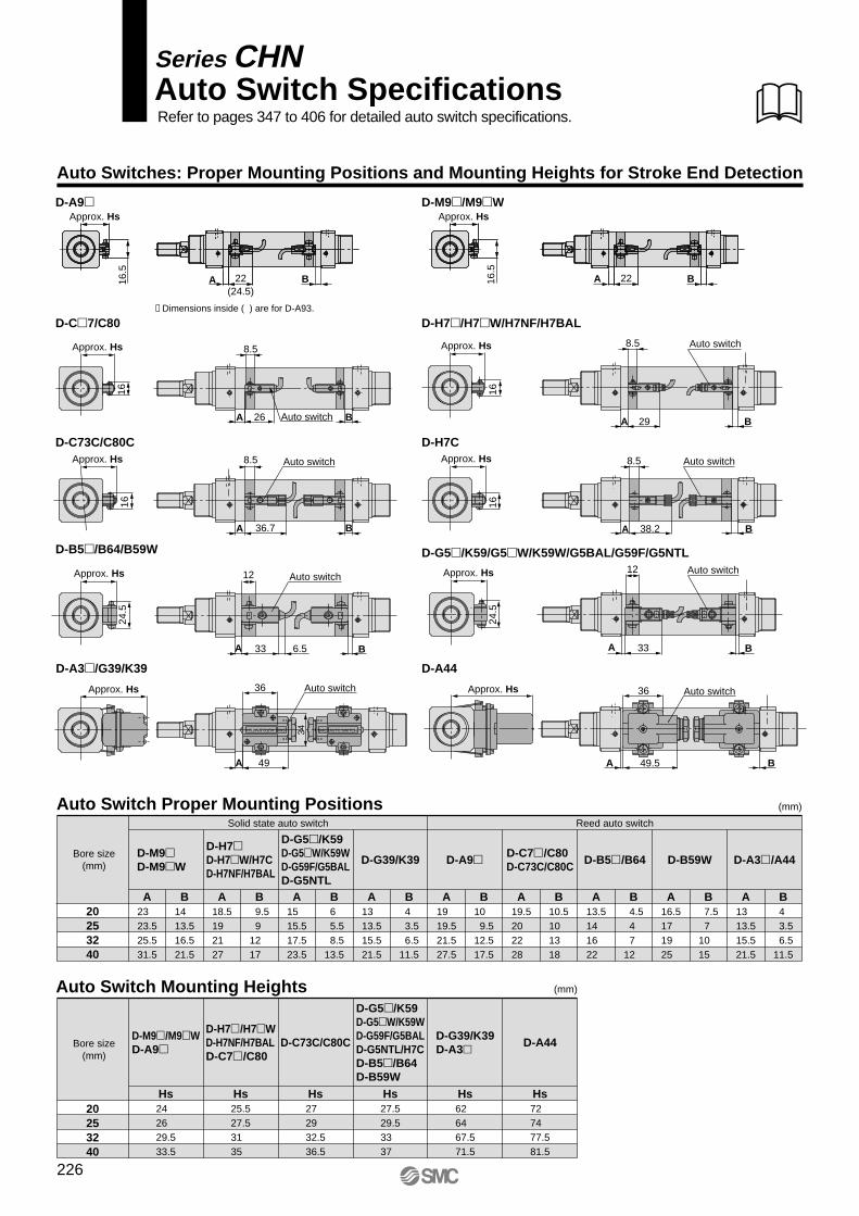
Auto Switches: Proper Mounting Positions and Mounting Heights for Stroke End Detection
D-C�7/C80 D-H7�/H7�W/H7NF/H7BAL
D-A9� D-M9�/M9�W
D-A44
D-C73C/C80C D-H7C
D-B5�/B64/B59W
Approx. Hs
16
Approx. Hs
16
8.5
A 26 BAuto switch
Approx. Hs
16
8.5
A 29 B
Auto switch
Approx. Hs
16
8.5
A 38.2 B
Auto switch
Approx. Hs 36
A B49.5
Auto switch
8.5
A 36.7 B
Auto switch
Approx. Hs
24.5
12
A 33 6.5 B
Auto switch
Auto Switch SpecificationsSeries CHN
Refer to pages 347 to 406 for detailed auto switch specifications.
D-A3�/G39/K39
Approx. Hs 36
A 49
Auto switch
34 SMC AUTO SWITCH
SMCAUTO SWITCH
D-G5�/K59/G5�W/K59W/G5BAL/G59F/G5NTL
Approx. Hs
24.5
12
A 33 B
Auto switch
20253240
D-M9�D-M9�W
A23 23.525.531.5
D-H7�D-H7�W/H7CD-H7NF/H7BAL
A18.519 21 27
B14 13.516.521.5
B 9.59
12 17
D-G5�/K59 D-G5�W/K59WD-G59F/G5BALD-G5NTL
A15 15.517.523.5
B6
5.5 8.513.5
D-G39/K39
A13 13.515.521.5
B4
3.5 6.511.5
D-A9�
A19 19.521.527.5
B10 9.512.517.5
D-C7�/C80 D-C73C/C80C
A19.520 22 28
B10.510 13 18
D-B5�/B64
A13.514 16 22
B 4.54 7
12
D-B59W
A16.517 19 25
B 7.57
10 15
D-A3�/A44
A13 13.515.521.5
B4
3.5 6.511.5
Auto Switch Proper Mounting Positions
Auto Switch Mounting Heights
20253240
D-M9�/M9�WD-A9�
Hs24 26 29.533.5
D-H7�/H7�WD-H7NF/H7BALD-C7�/C80
Hs25.527.531 35
D-C73C/C80C
Hs27 29 32.536.5
D-G5�/K59D-G5�W/K59WD-G59F/G5BALD-G5NTL/H7CD-B5�/B64D-B59W
Hs27.529.533 37
D-G39/K39D-A3�
Hs62 64 67.571.5
D-A44
Hs72 74 77.581.5
(mm)
(mm)
B16.5
A 22
Approx. Hs
∗ Dimensions inside ( ) are for D-A93.
Approx. Hs
16.5
A 22(24.5)
B
Bore size(mm)
Solid state auto switch Reed auto switch
Bore size(mm)
226

CHQ
CHK�
CHN
CHM
CHS�
CH2�
CHA
D-�
RelatedEquipment
Minimum Auto Switch Mounting Stroke
Operating Range
∗ Since this is a guideline including hysteresis, not meant to be guaranteed. (Assuming approximately ±30% dispersion.)There may be the case it will vary substantially depending on an ambient environment.
Auto switch modelBore size
20
9 8
10.5
13.513.511.5
25
8.5 7.5
9.5
11.513 10
32
10 7
8.5
10 11.59
40
10.58
10
12 13.510.5
4.5 4 4 4.5
4.5 5 4.5
5.5 5 4.5
5
5
D-M9�D-M9�WD-H7�/H7CD-H7�WD-H7NF/H7BALD-G5�/K59/G59FD-G5�W/K59WD-G5BAL/G5NTLD-G39/K39D-A9�D-C7�/C80D-C73C/C80CD-B5�/B64D-B59WD-A3�/A44
(mm)
D-M9�/M9�WD-A9�
D-H7�/H7�WD-H7NF/H7BAL
D-C7�D-C80
D-H7CD-C73CD-C80CD-G5�/K59D-G5�W/K59WD-G59F/G5BAL/G5NTLD-B5�/B64
D-B59W
D-G39/K39D-A3�/A44
10
10
10
10
10
15
10
15 Note 1)
15
15
15
15
20
35
45 Note 1)
60
50
65
75
75
100
45 + 45 (n – 2)
60 + 45 (n – 2)
50 + 45 (n – 2)
65 + 50 (n – 2)
75 + 55 (n – 2)
75 + 55 (n – 2)
100 + 100 (n – 2)
Auto switch modelNumber of auto switches mounted
2 pcs. n pcs.Same surfaceDifferent surfaces Different surfaces Same surface
1 pc.
(mm)
(n = 2, 4, 6 …)
15 + 45(n – 2)
2
(n = 2, 4, 6 …)
15 + 45(n – 2)
2
(n = 2, 4, 6 …)
15 + 45(n – 2)
2
(n = 2, 4, 6 …)
15 + 50(n – 2)
2
(n = 2, 4, 6 …)
15 + 50(n – 2)
2
(n = 2, 4, 6 …)
20 + 50(n – 2)
2
35 + 30 (n – 2)(n = 2, 3, 4, 5 …)
D-A93D-M9�D-M9�W
Auto switch model
Different surfaces Note 1)
—
Same surface Note 1)
B-6
A-6 15
6
B
6
A
Auto switchD-M9�D-M9�W
Auto switches — 2 pcs.
15 to less than 20 stroke
45 to less than 50 stroke
45 to less than 55 stroke
Mount auto switches offset (in circumferential direction of cylinder tube) so that auto switch units and lead wires do not run up against each other.
The proper mounting position is at 6 mm inward from the end sur-face of the switch holder.
Note 1) Auto switch mounting (The adjustment as shown in the figures below is required with the following stroke ranges.)
227
Hydraulic Cylinder Series CHN
8-03-08-CHN.qxd 09.10.1 1:37 PM Page 1

Auto Switch Mounting Brackets: Part Nos.
[Stainless steel mounting screw kits]The following stainless steel mounting screw kits are available for use depending on the operating environment. (Switch mounting bands are not included and should be ordered separately.) BBA3: D-B5, D-B6, D-G5, and D-K5 BBA4: D-C7, D-C8, D-H7∗ When D-H7BAL switches are shipped mounted on a cylinder, the above stainless steel screws are used. Also,
when switches are shipped separately, BBA4, BBA3 is included.
Auto switch modelsBore size (mm)
D-M9�M9�WD-A9�D-H7�/H7�W/H7NFD-H7BAL/C7�/C80D-C73C/C80CD-G5�/G5�W/G59FD-G5BAL/G5NTLD-B5�/B64/B59WD-G39/K39/A3�/A44
ø20
BMA2-020
BA-01
BD1-01M
Note)
qBMA2-020wBJ3-1
ø25
BHN3-025
BHN2-025
BD1-02M
Note)
qBHN3-025wBJ3-1
ø32
BHN3-032
BGS1-032
BHN1-032
Note)
qBHN3-032wBJ3-1
ø40
BHN3-040
BH2-040
BDS-04M
Note)
qBHN3-040wBJ3-1
Partno.
Contents
BBA3
BBA4
Description
Auto switchmountingscrew set
size
M4 x 0.7 x 22L
M3 x 0.5 x 14L
pcs.
1
1
Applicable auto switch mounting bracket part nos.Applicable
auto switches
BA-01, BA-02, BA-32, BA-04, BA-05, BA-06, BA-08, BA-10BA2-020, BA2-025, BA2-032, BA2-040BA5-050, BHN2-025, BSG1-032BH2-040, BH2-050, BH2-080, BH2-100BAF-32, BAF-04, BAF-05, BAF-06, BAF-08, BAF-10BJ2-006, BJ2-010, BJ2-016BM2-020, BM2-025, BM2-032, BM2-040BMA2-020, BMA2-025, BMA2-032, BMA2-040, BMA2-050, BMA2-063BHN3-025, BHN3-032, BHN3-040
D-B5, B6D-G5, K5
D-C7, C8D-H7
Note) Two types of auto switch mounting bracket are used as a set.
Auto switch
Set Screw (Not used)
switch spacer (Stainless steel)e
Switch holder(Resin)
d
Switch bracket(Stainless steel)
c Auto switch mounting screwb
Auto switch mounting banda
∗ Solid state auto switches are also available with pre-wired connector. Refer to pages 389 and 390 for details.∗ Normally closed (N.C. = b contact), solid state auto switches (D-F9G, F9H) are also available. For details, refer to page 365.
Besides the models listed in “How to Order,” the following auto switches are applicable.Refer to pages 347 to 406 for detailed auto switch specifications.
Auto switch type Part no. FeaturesElectrical entryD-H7A1, H7A2, H7BD-G59, G5P, K59D-H7NW, H7PW, H7BWD-G59W, G5PW, K59WD-G5BALD-G5NTLD-G59FD-C73, C76, B53D-C80
—
Diagnostic indication (2-color display)
Water resistant (2-color display)With timer
With diagnostic output (2-color display)
—Without indicator light
Grommet (in-line)
Grommet (in-line)
Solid state
Reed
Stainless steel mounting screw kit details.
q BMA2-020, BHN3-��� are a set including a and b in the diagram.w BJ3-1 is a set including c, d, and e in the diagram.
228
Series CHN

How to Mount and Move the Auto Switch
Mounting the Auto Switch
1. Attach the switch bracket to the switch holder.(Fit the convex part of the switch bracket over the concave part of the holder.)
2. Mount the auto switch mounting band to the cylinder tube.
3. Set the switch holder between the reinforcing plates of the auto switch mounting band which is already attached to the cylinder.
4. Insert the auto switch mounting screw in the hole of the reinforcing plate through the switch holder, and thread it into the other plate. Tighten the screw temporarily.
5. Remove the set screw attached to the auto switch.
6. Attach the switch spacer to the auto switch.
7. Insert the auto switch with a switch spacer from the back of the switch holder and set it at the specified position.(Insert the auto switch with an angle of approximately 10 to 15°. See figure 1.)
8. To secure the auto switch, tighten the switch mounting screw with the specified torque (0.8 N·m to 1.0 N·m).
Adjusting the Switch Position
1. Unloosen the auto switch mounting screw 3 turns to adjust the auto switch set position.
2. Tighten the screw as described above (8) after adjustment.
Dismounting Auto Switch
1. Remove the auto switch mounting screw from the switch holder.
2. Move the auto switch back towards the position where it stops at the lead wire side.
3. Hold up the lead wire side of the auto switch at the angle of around 45°.
4. Maintain the angle, and pull back the auto switch obliquely at the same angle.
Note 1) Be careful not to pull or strain the lead wires.Be careful not to apply excess tensile force (over 10 N) to the auto switches.Adjust the auto switch position after sufficiently loosening its screw. For the band mounting type BJ3-1, loosen the screw three rotations or more.
Note 2) Be sure to use the switch spacer and switch bracket for the band mounting type.Use together with the conventional auto switch mounting bands (brackets) BMA2-020, or BHN3-���. Confirm that a switch spacer is mounted to the end of the auto switch before fastening the auto switch. If the switch bracket is not mounted, the auto switch may move after installation.
• BMA2-020 and BHN3-��� are a set of a and b shown above. • BJ3-1 is a set of c, d and e shown above.
The parts indicated in are attached to BJ3-1.
Face the rubber lining surface upward.
Reinforcingplates
60° to 80°
Switch bracket(Stainless steel)
Switch spacer(Stainless steel)
Auto switch
Set screw (unused)
Switch holder(Resin)
d
e
c
Auto switch mounting screw(Low carbon steel wire rod)
r
i
u
q
e
w
y
tb
Figure 1. Switch insert angle
Aporox. 10 to 15°
Auto switch mounting banda
How to Mount and Move the Auto Switch
<Applicable auto switch>Solid state ······ D-M9N, D-M9P, D-M9B
D-M9NW, D-M9PW, D-M9BWReed ··············· D-A90, A93, A96
Mounting correctly Mounting incorrectly
1. Tighten the screw under the specified torque when mounting auto switch.
2. Set the auto switch mounting band perpendicularly to cylinder tube.
Caution
229
Hydraulic Cylinder Series CHN
CHQ
CHK�
CHN
CHM
CHS�
CH2�
CHA
D-�
RelatedEquipment
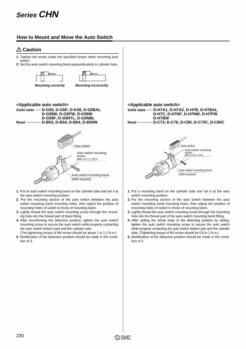
How to Mount and Move the Auto Switch
1. Put an auto switch mounting band on the cylinder tube and set it at the auto switch mounting position.
2. Put the mounting section of the auto switch between the auto switch mounting band mounting holes, then adjust the position of mounting holes of switch to those of mounting band.
3. Lightly thread the auto switch mounting screw through the mount-ing hole into the thread part of band fitting.
4. After reconfirming the detection position, tighten the auto switch mounting screw to secure the auto switch while properly contacting the auto switch bottom part and the cylinder tube. (The tightening torque of M4 screw should be about 1 to 1.2 N·m.)
5. Modification of the detection position should be made in the condi-tion of 3.
<Applicable auto switch>Solid state ······ D-G59, D-G5P, D-K59, D-G5BAL
D-G59W, D-G5PW, D-K59WD-G59F, D-G5NTL, D-G5NBL
Reed ··············· D-B53, D-B54, D-B64, D-B59W
1. Put a mounting band on the cylinder tube and set it at the auto switch mounting position.
2. Put the mounting section of the auto switch between the auto switch mounting band mounting holes, then adjust the position of mounting holes of switch to those of mounting band.
3. Lightly thread the auto switch mounting screw through the mounting hole into the thread part of the auto switch mounting band fitting.
4. After setting the whole body to the detecting position by sliding, tighten the auto switch mounting screw to secure the auto switch while properly contacting the auto switch bottom part and the cylinder tube. (Tightening torque of M3 screw should be 0.8 to 1 N·m.)
5. Modification of the detection position should be made in the condi-tion of 3.
<Applicable auto switch>Solid state ······ D-H7A1, D-H7A2, D-H7B, D-H7BAL
D-H7C, D-H7NF, D-H7NW, D-H7PWD-H7BW
Reed ··············· D-C73, D-C76, D-C80, D-C73C, D-C80C
Mounting correctly Mounting incorrectly
1. Tighten the screw under the specified torque when mounting auto switch.
2. Set the auto switch mounting band perpendicularly to cylinder tube.
Caution
Auto switch
Auto switch mounting band (With bracket)
Auto switch mounting screwM4 x 0.7 x 22 l
Auto switch mounting band
(With bracket)
Auto switch
Auto switch mounting screwM3 x 0.5 x 14 l
230
Series CHN

How to Mount and Move the Auto Switch
How to Mount and Move the Auto Switch
1. Loosen the auto switch mounting screws at both sides to pull down the hook.
2. Put an auto switch mounting band on the cylinder tube and set it at the auto switch mounting position, and then hook the band.
3. Screw lightly the auto switch mounting screw.4. Set the whole body to the detecting position by sliding, tighten the
mounting screw to secure the auto switch. (The tightening torque should be about 2 to 3 N·m.)
5. Modification of the detecting position should be made in the condi-tion of 3.
<Applicable auto switch>Solid state ······ D-G39, D-K39Reed ··············· D-A33, D-A34, D-A44
D-A3, D-G3/K3 type
D-A4
Mounting correctly Mounting incorrectly
1. Tighten the screw under the specified torque when mounting auto switch.
2. Set the auto switch mounting band perpendicularly to cylinder tube.
Caution
Auto switch
Auto switch mounting screwM5 x 0.8 x 16 l
Auto switch mounting screwM5 x 0.8 x 16 l
Auto switch mounting band
Auto switch mounting band
Hook
Hook
Auto switch
231
Hydraulic Cylinder Series CHN
CHQ
CHK�
CHN
CHM
CHS�
CH2�
CHA
D-�
RelatedEquipment