software management within product...
TRANSCRIPT

Software management within Product
Development
Bachelor of Science Thesis in Mechatronics Engineering
ERIK JOHANSSON
SIV ROMERO SKOGH
HENRIK SVENSSON
Department of Product & Production Development
Examiner: Mats Alemyr
CHALMERS UNIVERSITY OF TECHNOLOGY
Gothenburg, Sweden, 2011

___________________________________________________________________________
I
Foreword
This thesis is part of our Bachelor of Science degree in Mechatronics, conducted at Chalmers
University of Technology. The assignment has been carried out at Prototype Vehicles, Volvo Car
Corporation, in the fall of 2010.
First and foremost we would like to thank our mentor at Volvo, Magnus Wennström, for the
opportunity and the great support. It has been a very interesting experience, continuously
providing more knowledge and insight. Mats Alemyr, our mentor at Chalmers, has also been a
committed and valuable help.
There are many people who we would like to thank for their tireless cooperation and substantial
help. That would unfortunately cover a couple of pages.
However, we would like to send special thanks to:
Bengt Jalnäs, Volvo
Johnny Georgiou, Volvo
Kerstin Skarp, Volvo
Finally, we are proud to present the result of some extensive work, enjoy!
Gothenburg, January 2011
Erik Johansson
Siv Romero Skogh
Henrik Svensson

___________________________________________________________________________
II
Abstract
The software management within Product Development at VCC, Volvo Car Corporation, in
Torslanda has been studied. Prototype Vehicles has a problem with late deliveries of software for
their test objects. In order to find the cause of this, the units involved before Prototype Vehicles
have been studied.
The first step of the project was to map up the actual current process. This was done by
interviewing people in different parts of the organization. In some ways, the developed map
differs from the formal one. It was also compared with the hardware process, which has a better
delivery precision.
The next step was to suggest changes to improve the software handling. Key individuals were
interviewed, more pointed questions were asked and a flowchart was developed including
suggestions for improvement. In order to structure the problems, a report was made with the
areas sorted as Units, Roles, Tools and Meetings, listing the problems discovered.
Task Leaders are responsible for the development of software for their corresponding node. The
role has been studied more extensively because a large part of the delays naturally occur during
this stage in the project. The study has been conducted by interviewing a number of Task
Leaders. The information has been compared and analyzed.
The character of the problems found is mainly communicational and structural. A number of
areas have been given suggestions for improvement which have already started to be
implemented.

___________________________________________________________________________
III
Sammanfattning
Programvaruhanteringen inom produktutveckling på Volvo Personvagnar i Torslanda har
granskats. Avdelningen ‟Komplett bil‟ har ett problem med försenade leveranser av programvara
för sina provobjekt. För att hitta orsakerna till detta har enheterna involverade före ‟Komplett bil‟
studerats.
Det första steget i uppdraget var att kartlägga den nuvarande processen. Detta gjordes genom att
intervjua personer i olika delar av organisationen. Bitvis skiljer sig kartläggningen från den
formella planen. Den jämfördes också mot hårdvaruprocessen, eftersom hårdvaran har bättre
leveransprecision.
Nästa steg var att föreslå förändringar för att förbättra hanteringen av programvaran.
Nyckelpersoner intervjuades, mer konkreta frågor ställdes och ett flödesschema med förslag på
förbättringar utvecklades. För att strukturera problemen sammanställdes en rapport med de olika
områdena sorterade efter Avdelningar, Roller, Verktyg och Möten. I denna listades de problem
som uppdagats.
Konstruktionsuppdragsledare är ansvariga för utveckling av programvara för deras respektive
nod. Denna roll har studerats ytterligare eftersom en stor del av förseningarna av naturliga skäl
uppkommer under detta skede i projektet. Detta har genomförts genom intervjuer med ett antal
Konstruktionsuppdragsledare. Informationen har jämförts och analyserats.
De flesta upptäckta problem har den gemensamma nämnaren att de har med kommunikation
eller struktur att göra. Förslag på förbättringar har framförts för ett antal områden och har redan
börjat implementeras.

___________________________________________________________________________
IV
Table of contents
1 Introduction ........................................................................................................................1
1.1 Background ............................................................................................................................ 1
1.2 Aim......................................................................................................................................... 1
1.3 Delimitations.......................................................................................................................... 2
1.4 Clarification of the issue ......................................................................................................... 2
1.5 Report outline ........................................................................................................................ 2
2 Theoretical framework .......................................................................................................3
2.1 Organization .......................................................................................................................... 3
2.2 Communication ...................................................................................................................... 4 2.2.1 Interpreting messages ..................................................................................................................... 4 2.2.2 Feedback ......................................................................................................................................... 4 2.2.3 In-group – Out-group ....................................................................................................................... 4 2.2.4 Our consciousness ........................................................................................................................... 5
2.3 Destructive social phenomenon’s .......................................................................................... 6
2.4 Change process ...................................................................................................................... 6
2.5 Lean Product Development System (LPDS) ............................................................................ 7
3 Introduction of Volvo ..........................................................................................................9
4 The structure of the electric system in a Volvo .................................................................11
4.1 The different network buses ................................................................................................ 11 4.1.1 CAN ............................................................................................................................................... 12 4.1.2 LIN................................................................................................................................................. 12 4.1.3 MOST ............................................................................................................................................ 13
4.2 Number of ECUs the past decade ......................................................................................... 13
4.3 Difficulties to implement a function..................................................................................... 14
5 Method .............................................................................................................................15
5.1 Define the project ................................................................................................................ 15
5.2 Measure the current situation ............................................................................................. 15
5.3 Analyze to identify causes .................................................................................................... 16
5.4 Improve................................................................................................................................ 17
5.5 Control ................................................................................................................................. 17
6 Function implementation..................................................................................................18
6.1 GPDS, Global Product Development System ........................................................................ 18

___________________________________________________________________________
V
6.2 C-note, Change note............................................................................................................. 18
6.3 Simplified process flow ........................................................................................................ 20
6.4 Map explanation .................................................................................................................. 22
7 The current software process ............................................................................................23
7.1 Treated areas within the process ......................................................................................... 23 7.1.1 Unit / Role: Function Designer ....................................................................................................... 26 7.1.2 Unit / Role: System Designer .......................................................................................................... 27 7.1.3 Unit / Role: Software Designer ....................................................................................................... 28 7.1.4 Unit / Role: Software Tester / Acceptance test ............................................................................... 30 7.1.5 Unit / Role: SCC, Software Coordination Center / PCM, Program Control Manager ......................... 31 7.1.6 Unit / Role: A&V Diagnostics & ECU Platform (Verification team) Integrations and Functions tests 33 7.1.7 Unit / Role: POB, Test Objects Engineer (Provobjektsberedare) ..................................................... 35 7.1.8 Unit / Role: Boxcar Technicians ...................................................................................................... 36 7.1.9 Role: UPM, Unit Program Manager at EESE (DPL, Delprojektledare) ............................................... 37 7.1.10 Role: Task Leader (KU, Konstruktionsuppdragsledare)................................................................ 38 7.1.11 Tool / Meeting: TRM, Time Review Meeting .............................................................................. 40 7.1.12 Tool / Meeting: SW-DRM & NCM .............................................................................................. 41 7.1.13 Tool / Meeting: CRB, Configuration & Release Board ................................................................. 42 7.1.14 Tool / Meeting: FIP, Function Implementation Plan .................................................................... 43 7.1.15 Tool / Meeting: Purpose of Series Document ............................................................................. 44
7.2 Visualizing problems of the software process ...................................................................... 45
8 Task Leaders .....................................................................................................................46
8.1 Indicators of performance.................................................................................................... 47 8.1.1 MRD – Material Required Date ...................................................................................................... 47 8.1.2 Completeness of delivered software & documentation .................................................................. 48 8.1.3 Delivery flaws discovered at Software Coordination Center ............................................................ 48
8.2 Self assessments .................................................................................................................. 49
8.3 Problems discovered ............................................................................................................ 50
8.4 Dependency on initiatives .................................................................................................... 51 8.4.1 Solution - Clear and known processes ............................................................................................ 52 8.4.2 Incentive system ............................................................................................................................ 53 8.4.3 Support from Product Development Manager necessary ............................................................... 53
9 Applying theory ................................................................................................................54
9.1 Hardware vs. Software handling .......................................................................................... 54
9.2 Isolated groups .................................................................................................................... 55
9.3 Feedback and handshaking .................................................................................................. 55
9.4 Organizations inside the organization .................................................................................. 57
9.5 Finding common ground ...................................................................................................... 58
9.6 Resistance against change.................................................................................................... 58
9.7 Lean Product Development System ..................................................................................... 59
___________________________________________________________________________
VI
10 Common problems and suggested solutions ....................................................................60
10.1 Structure .............................................................................................................................. 60 10.1.1 Building of Boxcar ..................................................................................................................... 60 10.1.2 MRD0/MRD1 and acceptance test ............................................................................................. 60 10.1.3 SCC, Software Coordination Center ........................................................................................... 60
10.2 Communication: ................................................................................................................... 62 10.2.1 Feedback .................................................................................................................................. 62 10.2.2 Feedback to Task Leaders .......................................................................................................... 62 10.2.3 Communication between departments ..................................................................................... 62 10.2.4 Communication between Task Leaders...................................................................................... 62 10.2.5 Communication between Task Leader and SW-supplier ............................................................. 63
10.3 Tools and systems: ............................................................................................................... 64 10.3.1 BOM-list.................................................................................................................................... 64 10.3.2 GPDS plan is not followed ......................................................................................................... 64 10.3.3 Purpose of Series ...................................................................................................................... 65 10.3.4 The FIP ...................................................................................................................................... 65 10.3.5 The KDP-system ........................................................................................................................ 65
10.4 General problems: ............................................................................................................... 66 10.4.1 Running changes ....................................................................................................................... 66 10.4.2 Putting out fires ........................................................................................................................ 66 10.4.3 Missing a deadline .................................................................................................................... 66 10.4.4 Software importance ................................................................................................................ 67
10.5 Other problems: ................................................................................................................... 68 10.5.1 Implementing of the Function ................................................................................................... 68 10.5.2 E2 and M1................................................................................................................................. 68 10.5.3 Contracts (Task Leader - Supplier) ............................................................................................. 68 10.5.4 DPL ........................................................................................................................................... 69 10.5.5 Acceptance test ........................................................................................................................ 69 10.5.6 SW-DRM ................................................................................................................................... 69
10.6 The V-model ......................................................................................................................... 70
10.7 Recommendation ................................................................................................................. 71
11 Conclusion .........................................................................................................................72
11.1 Experiences .......................................................................................................................... 72
11.2 Credibility analysis ............................................................................................................... 73
11.3 Recommendations ............................................................................................................... 73
11.4 Final words ........................................................................................................................... 73
References ................................................................................................................................75
Appendix A1 ...............................................................................................................................1
Appendix A2 ...............................................................................................................................2
Appendix B1 Current Flowchart ..................................................................................................3
Appendix B2 Suggested Flowchart .............................................................................................4

___________________________________________________________________________
VII
ABBREVIATIONS
Descriptions and/or explanations På Svenska
AVA Analyze and Verification responsible Analys och Verifieringsansvarig
AVB Analyze and Verification
Requirements
Analys & Verifieringsbehov
BMS Business Management System
BOM Bill of Material
– the term used to describe the “parts
list” of components needed to complete a sellable end-item
Term som används för att beskriva listan av
komponenter som behövs för att färdigställa en
säljbar produkt
Boxcar – the complete electrical system built
on a table
Lådbil
C-note Change note ÄO -Ändringsorder
CAN Controller Area Network
CEM Central Electronic Module
CME Central Manufacturing Engineer
CPM Chief Program Manager
CRB Configuration and Release Board
DPL Unit Program Manager Delprojektledare
ECU Electronic Control Unit
– also called “node”
Nod
EESE Electrical and Electronics Systems Engineering
– a department within Product
Development
– elavdelningen inom produktutveckling på VCC
ESOW Engineering Statement Of Work
FAD Function Area Description
FDJ Final Data Judgment
– all engineering designs are completed, “pencil down”
– den tidpunkt då all utvecklingsarbeta skall vara
färdigt
FIP Function Implementation Plan Funktionsimplementationsplan
FSR Final Status Report
GPDS Global Product Development System – a plan describing all program logics
(milestones) to be held during the
projects
Globalt Produktutvecklings-system

___________________________________________________________________________
VIII
HIL Hardware In the Loop
HPD Handling Of Part Deviation – hantering av atrikelavvikelser
KDP Engineering Database KonstruktionData Personvagnar
KU Task Leader Konstruktionsuppdragsledare
LIN Local Interconnect Network
M1DJ M1 Data Judgment
MOST Media Oriented System Transport
MRD Material Required Date
NCM Node Check Meeting
OBD On Board Diagnostics
PA Program Approval
PCM Program Configuration Manager
PD Product Development
– the development unit within VCC
PEM Program Engineer Manager TPL – Teknisk Projektledare
POB Test object engineer Provobjektsberedare, Provobjektsbehov
PP Pilot Production
PS Program Start
PSC Program Strategy Confirmed
PSS Product System Structure
PTC Program Target Compatibility
PTCC Program Target Compatibility
Checkpoint
SCC Software Coordination Center
SDB Signal Database Signaldatabas
SKB SRD, System Requirement Description SystemKravsBeskrivning
SOP Start of Production
SRD System Requirement Description SKB, SystemKravsBeskrivning
SU Systemuppdragsledare
SW-DRM
Software Design Review Meeting
SWRS Software Requirement Specification
Task Leader
Task Leader KU Konstauktionsuppdragsledare eller
Komponentuppdragsledare
TPL PEM - Program Engineer Manager Teknisk Projektledare

___________________________________________________________________________
IX
Technical Project Leader
TRM Time Review Meeting
TT Tooling Trail
TTC Technology Target Compatibility
UN Under body
UP Upper body
VCC Volvo Car Corporation
VIDA Vehicle Information & Diagnostics
for Aftersales
VP Verification Prototype
ÄO C-note – Change note Ändringsorder
___________________________________________________________________________
X
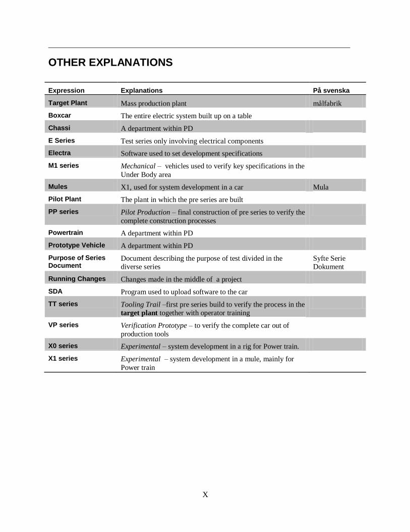
OTHER EXPLANATIONS
Expression Explanations På svenska
Target Plant Mass production plant målfabrik
Boxcar The entire electric system built up on a table
Chassi A department within PD
E Series Test series only involving electrical components
Electra Software used to set development specifications
M1 series Mechanical – vehicles used to verify key specifications in the
Under Body area
Mules X1, used for system development in a car Mula
Pilot Plant The plant in which the pre series are built
PP series Pilot Production – final construction of pre series to verify the
complete construction processes
Powertrain A department within PD
Prototype Vehicle A department within PD
Purpose of Series Document
Document describing the purpose of test divided in the diverse series
Syfte Serie Dokument
Running Changes Changes made in the middle of a project
SDA Program used to upload software to the car
TT series Tooling Trail –first pre series build to verify the process in the target plant together with operator training
VP series Verification Prototype – to verify the complete car out of
production tools
X0 series Experimental – system development in a rig for Power train.
X1 series Experimental – system development in a mule, mainly for
Power train

___________________________________________________________________________
1
1 INTRODUCTION
The current situation within software development and delivery for prototypes doesn‟t meet
the required levels. A need for a new process has occurred. Software has a lower on-time-
delivery precision than the corresponding hardware - about 40 percent compared to 90
percent.
1.1 Background
Until recent years Volvo was a player focusing on robustness and safety. Little effort was
given to electrical features and high performance. That has all changed. Since the mid 90‟s,
Volvo has entered the competition in the premium segment, making products increasingly
advanced and diverse.
Entering the IT-era has also given a new dimension to car development. The amount of
electrical functions which used to be relatively constant from one generation of cars to the
next has increased in a way that no one could have predicted a few years ago. IT-services
have a short life and are updated constantly. An overwhelming amount of software is now
involved in every part of a vehicle.
This does not cope well with the way products traditionally have been developed. Both the
infrastructure and routines need an update.
Infrastructure
All hardware / software parts are released through a database called KDP, Konstruktionsdata
Personvagnar. It was introduced in the late 70‟s and is used all the way from development to
aftermarket. Many other systems are used for software handling but no automatic
synchronization with KDP is possible. The demands for a new software system have not yet
been met. The handling of software becomes difficult because of the amount of systems that
are used, and the lack of automatic synchronization.
Coordination and routines
For a long time the software only represented a tiny part of the product development.
Therefore the software processes didn‟t need as much coordination as the hardware process.
It performed well having a small group of software designers that worked under less
regulated conditions. As the development expanded, the structure and thinking partly
remained the same, both within the development units and higher in the hierarchy. This lack
of structure leaves a huge burden on each group of software designers and makes the process
very dependent on the experience within the group.
1.2 Aim
The project aims to improve the process of software management to better correspond to the
hardware management in terms of delivery precision. It also aims to understand the current
software process to then be able to compare against the hardware process. Finally the purpose
was to analyze the possibilities to apply the structure of hardware management to the
software management.
___________________________________________________________________________
2
1.3 Delimitations
Developing a new model involves a lot of different steps. The delimitations were set to only
involve M1-, VP-series and Boxcars (see 7.1.8).
M1 corresponds to building the UN, Under body.
VP corresponds to building the entire car - both UN and UP, Upper body.
Boxcars include the entire electric system. It is built up on a table and is conducted in
five different E-series (see 6.1), as functions continuously become ready for testing.
The scope of units to investigate had to be wide because of their dependency on each other.
1.4 Clarification of the issue
There are many reasons causing the software deliveries to be delayed. One of the reasons is
that an entire unitary process is missing. Questions to be answered within this thesis are:
How does the current process work today? How can the current process be improved? Can
the software-process be as organized as the hardware process?
The first stage of the assignment was to visualize the current software process and
software deliveries for the building of prototypes and Boxcars.
The second part of the assignment was to develop and optimize the current process
corresponding to the GPDS plan, Global Product Development System (see 6.1).
The third part of the assignment was to suggest conceivable changes to implement
within Product Development. Possibilities to implement a BOM, Bill of Material
which is a specified list of demanded parts/software for each series were also
investigated.
1.5 Report outline
In the following section, Chapter 2, the theoretical framework is presented. In Chapter 3
Volvo history is introduced to present the company‟s growth and position in the world.
Chapter 4 describes the electronics growths for the past decades to explain the development
situation of today. Then Chapter 5 describes the method used in how the work was
accomplished. In Chapter 6 a simplified description of the product development process at
Volvo is described. Chapter 7 describes the software process step by step and problems
during the process are highlighted and summarized. In Chapter 8 a study of the Task Leaders
work situation is presented. In Chapter 9 the theoretical framework is merged with the found
situation within software product development at VCC, Volvo Car Corporation. Chapter 10
summarizes common problems and suggested solutions are given to most of them. Finally, in
Chapter 11 our conclusions for this work are presented.

___________________________________________________________________________
3
2 THEORETICAL FRAMEWORK
In big organizations there is always the problem of communication. Since the scope of the
report covers a huge amount of units and people, working in projects over a long period of
time, organizational as well as communications theory are interesting to compare against.
This includes issues like feedback, groupthink and aspects of change processes.
Comparison against Lean Product Development System has also been done.
2.1 Organization
For every activity, some form of organization is needed. The concept of organization is
usually associated with the formal organization. It is usually described in terms of
organizational models in which decision-making, information channels and work processes
are described. It also addresses the responsibilities of different managers. The various tasks
are set by job descriptions.
There is also an informal aspect of the organization. The informal organization gives life to
the organization. The employee tries to shape his work to suit his needs. Similarly, each team
will shape their part.
The formal organization is based on the employer's goals for the business. The informal
organization is formed by the confrontation between all the demands and expectations on the
business from employers, employees, users of the organization and its environment. While
the formal organization is set by its management, the informal organization is shaped by the
way its members are functioning, and their relation to each other. The formal organization is
usually written down. The informal organization is however very rarely documented. It must
be learned by working within the organization. The informal organization has decision and
information channels of its own. The coffee breaks as forums for information exchange are
often just as important as official meetings. In the informal organization a person can have a
very different influence than what is meant in the formal.
While the formal organization describes how the work is planned, the informal organization
is adjusted to the real world. The informal and the formal organization need to be consistent
with each other for a business to function. It‟s unusual that the formal and informal
organizations are completely separated. However, there are often differences between the two
types of organizations. Sometimes there are parts of the formal organization that don´t work.
It has therefore been replaced by an informal organization. There can also be major
differences between the two. This is usually the case when the organization is unbalanced,
such as a poorly planned organizational change or when the objectives of the business are not
clearly stated or in conflict. Sometimes it´s through the informal decision-making and
information routes the real decisions and important information are carried out - the formal
rules are just for show. (Granér 1994)

___________________________________________________________________________
4
2.2 Communication
The basis of the communication process is that a sender conveys a message to a recipient.
The recipient gives some kind of response to the sender's message. But while the transmitter
is talking, he receives non-verbal and symbolic messages. As receivers, our minds register
what the world gives. However, we do not record all available information. We make a
selection based on what we deem important. This is called selective perception and is
necessary for us not to be overwhelmed by all the impressions that constantly assault us.
Selection is governed by our experiences and expectations. We register what we think is
needed, to protect us from various types of hazards. (Granér 1994)
2.2.1 Interpreting messages
We imagine that it is the sender‟s thoughts we are interpreting. Instead it is our internal image
of a message we interpret. We therefore don´t necessarily see the real point. This
interpretation may be more or less consistent with the sender's intention. We don‟t know if
our interpretation is correct before we have given a response to the sender's message. Thus,
the recipient has become the transmitter. There is a distinction between one-and two-way
communication. One-way communication means there is no response to the transmitter. A
typical example of one-way communication is conveyed by mass media. The result is a
situation where the transmitter never knows if the message is understood correctly. (Granér
1994)
2.2.2 Feedback
One type of feedback is to give confirmation of what you understand. As transmitters we are
often careless in getting confirmation that the recipient has understood. We may assume that
all has been understood if no one says otherwise. Alternatively, we ask if all is understood
and are pleased to get an affirmative answer. But that can just as well be because they were
not listening or they thought they understood, but didn´t.
When we do not feel understood, we often react by talking even more about the same thing.
Spontaneously, we believe that there is a problem on the content level, but that‟s not always
the case. A better solution is often to communicate about the communication process - why it
doesn‟t work. (Granér 1994)
2.2.3 In-group – Out-group
Groups and organizations with fixed boundaries and poor communication often have a way
of thinking about themselves and others. This is usually described in terms of "in-group –
out-group-thinking". This kind of belief system requires that you don´t know the ones outside
the group. You don´t know what they do or how they do it. This way of thinking fills a
purpose in the group. “We are good, the threat is outside”. It creates a good atmosphere in the
group. Therefore members carefully avoid insight of the others‟ situation. Employees usually
look in a positive light at what their own group members are doing. What "the ones outside"
(the other units) are doing is examined with a much more critical eye. "We inside" are active
and committed, responsible and purposeful. When a problem occurs, it‟s because of
unfortunate circumstances - usually caused by those outside. "Those outside" have been
uninvolved or irresponsible. (Granér 1994)
___________________________________________________________________________
5
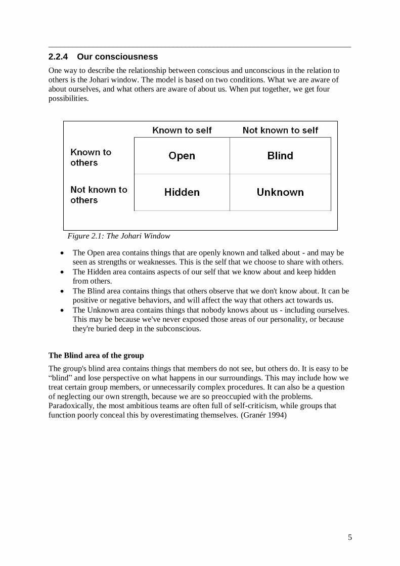
2.2.4 Our consciousness
One way to describe the relationship between conscious and unconscious in the relation to
others is the Johari window. The model is based on two conditions. What we are aware of
about ourselves, and what others are aware of about us. When put together, we get four
possibilities.
Figure 2.1: The Johari Window
The Open area contains things that are openly known and talked about - and may be
seen as strengths or weaknesses. This is the self that we choose to share with others.
The Hidden area contains aspects of our self that we know about and keep hidden
from others.
The Blind area contains things that others observe that we don't know about. It can be
positive or negative behaviors, and will affect the way that others act towards us.
The Unknown area contains things that nobody knows about us - including ourselves.
This may be because we've never exposed those areas of our personality, or because
they're buried deep in the subconscious.
The Blind area of the group
The group's blind area contains things that members do not see, but others do. It is easy to be
“blind” and lose perspective on what happens in our surroundings. This may include how we
treat certain group members, or unnecessarily complex procedures. It can also be a question
of neglecting our own strength, because we are so preoccupied with the problems.
Paradoxically, the most ambitious teams are often full of self-criticism, while groups that
function poorly conceal this by overestimating themselves. (Granér 1994)

___________________________________________________________________________
6
2.3 Destructive social phenomenon’s
Group think
Although adaptation is necessary for cooperation, the conformance efforts will become
inhibiting if the limits of differences are too narrow. Too united groups are poor problem
solvers. They tend to quickly reach a common conclusion, but they also miss important
aspects of the problem because no one doubts that the solution is the best one. A phenomenon
that illustrates this is usually called group think.
Regression
In strenuous, critical or stressful situations we tend to revert to a less mature way of acting.
Partially our reactions resemble those we used as children in difficult situations. When the
job seems too difficult, we feel a need for strong leaders - a mother or father figure - who take
care of everything for us. Another example is to revert to a childish attitude, become defiant,
whining or pulling away.
Projection
Unconsciously the individual tries to liberate himself from internal stress by attributing
someone else what he did not want to admit. The own psyche is like a movie projector and
others become a display of their own fantasies or feelings. A person feels in a bad mood but
does not want to acknowledge it. Instead he is annoyed by how irritated others seem to be.
Moreover, it is often projections of feelings of inferiority and incompetence. Those who have
good self-esteem tend to lack the need to disparage others.
2.4 Change process
When planning changes, it is crucial that the organization's informal side is not neglected. A
supervisor at the "floor" knows this. No matter how logically correct a change may seem, it
will not be well implemented without staff support. Managers directly related to the business
understand the importance of staff satisfaction and engagement.
Among politicians and in organizational and management teams there is often a tendency to
see people in the organization as bricks that can be moved around in a game and conduct the
same function wherever placed. Thus, it is believed that units can be split and merged,
resources rearranged and changes made to the goal without taking into account the staff's
reactions. This is obviously an illusion.
A change begins when a problem from any part of the group or organization cannot be
managed based on the existing structure. If the change is originating from below, it is
welcomed by the employees, and leads to activity and enthusiasm. (Granér 1994)

___________________________________________________________________________
7
2.5 Lean Product Development System (LPDS)
The widely adapted Japanese manufacturing concept is known as Lean Production and was
noticed world widely through a 1990‟s best seller called The Machine That Changed the
World: The story of Lean Production. The book describes “the movement of automobile
manufacturing from craft production to mass production to lean production” telling the Henry
Ford story of the making of cheap cars for the masses; the Toyota story, manufacturing cars
without being able to afford the enormous necessary investments of the required machines for
mass production.
Lean thinking is about eliminating wastes, adding nothing but value. Mary Poppendieck, a
leading pioneer of Lean software development, has translated The Seven Wastes of
Manufacturing identified by Taiichi Ohono, the mastermind of the Toyota Production System
(TPS) to The Seven Wastes of Software Development. Mary describes in her article
“Principles of Lean Thinking” how Extreme Programming, a set of practices which focuses
on rapid software development, works to eliminate the seven wastes of software
development:
Table 2.1: How Extreme Programming works to eliminate the seven wastes of software
development:
(Poppendieck 2002)
According to Morgan and Liker the used system model to describe Toyota‟s PD System has
three primary subsystems: 1) Process, 2) Skilled People and 3) Tools & Technology, “these
three subsystems are interrelated and interdependent and affect an organization‟s ability to
achieve its external purpose” shown in table above. This is based on the sociotechnical
system theory (STS) partly driven by European experiments with workplace democracy and
by American academics with engineering and social science backgrounds. STS says that “to
be successful, an organization must find the appropriate fit between the social and technical
system that fits the organizational purpose and the external environment”, meaning that “the
technical system includes the policies and standard operating procedures of an organization,
including the culture that emerges through the interaction of those people”.
The Seven Wastes of
Manufacturing
The Seven Wastes of
Software Development
How Extreme Programming Addresses
Waste
Overproducing Extra Features Develop only for today‟s stories
Inventory Requirements Story cards are detailed only for the
current iteration
Extra Processing Steps Extra Steps Code directly from stories; get verbal
clarification directly from customers
Motion Finding Information Have everyone in the same room;
customer included
Defects Defects Not Caught by Tests Test first; both developer tests and
customer tests
Waiting Waiting, Including
Customers
Deliver in small increments
Transportation Handoffs Developers work directly with customers
___________________________________________________________________________
8
Lean Product
Development System
1. Establish Customer-Defined Value to Separate Value-Added from Waste.
2. Front-Load the Product Development Process to Explore Thoroughly Alternative Solutions while there is Maximum Design Space.
3. Create a Leveled Product Development Process Flow 4. Utilize Rigorous Standardization to Reduce Variation, and
Create Flexibility and Predictable Outcomes.
5. Develop a Chief Engineer System to Integrate Development from Start to Finish.
6. Organize to Balance Functional Expertise and Cross-functional Integration.
7. Develop Towering Technical Competence in all Engineers.
8. Fully Integrate Suppliers into the Product Development System.
9. Build in Learning and Continuous Improvement.
10. Build a Culture to Support Excellence and Relentless
Improvement.
11. Adapt Technology to Fit your People and Process.
12. Align your Organization through Simple, Visual communication.
13. Use Powerful Tools for Standardization and Organizational Learning
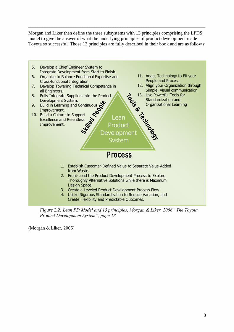
Morgan and Liker then define the three subsystems with 13 principles comprising the LPDS
model to give the answer of what the underlying principles of product development made
Toyota so successful. Those 13 principles are fully described in their book and are as follows:
(Morgan & Liker, 2006)
Figure 2.2: Lean PD Model and 13 principles, Morgan & Liker, 2006 “The Toyota
Product Development System”, page 18
___________________________________________________________________________
9
3 INTRODUCTION OF VOLVO
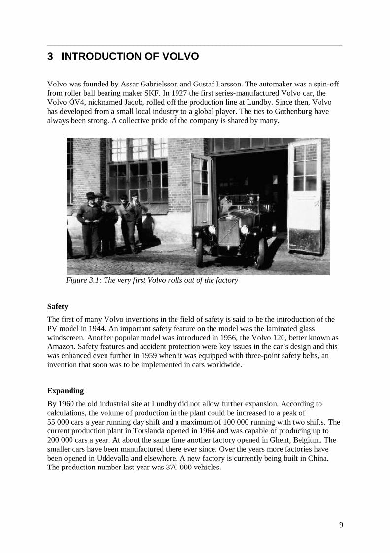
Volvo was founded by Assar Gabrielsson and Gustaf Larsson. The automaker was a spin-off
from roller ball bearing maker SKF. In 1927 the first series-manufactured Volvo car, the
Volvo ÖV4, nicknamed Jacob, rolled off the production line at Lundby. Since then, Volvo
has developed from a small local industry to a global player. The ties to Gothenburg have
always been strong. A collective pride of the company is shared by many.
Figure 3.1: The very first Volvo rolls out of the factory
Safety
The first of many Volvo inventions in the field of safety is said to be the introduction of the
PV model in 1944. An important safety feature on the model was the laminated glass
windscreen. Another popular model was introduced in 1956, the Volvo 120, better known as
Amazon. Safety features and accident protection were key issues in the car‟s design and this
was enhanced even further in 1959 when it was equipped with three-point safety belts, an
invention that soon was to be implemented in cars worldwide.
Expanding
By 1960 the old industrial site at Lundby did not allow further expansion. According to
calculations, the volume of production in the plant could be increased to a peak of
55 000 cars a year running day shift and a maximum of 100 000 running with two shifts. The
current production plant in Torslanda opened in 1964 and was capable of producing up to
200 000 cars a year. At about the same time another factory opened in Ghent, Belgium. The
smaller cars have been manufactured there ever since. Over the years more factories have
been opened in Uddevalla and elsewhere. A new factory is currently being built in China.
The production number last year was 370 000 vehicles.
___________________________________________________________________________
10
The modern Volvo
A completely new and different Volvo was launched in June 1991. The Volvo 850 was
Volvo‟s first front wheel drive executive car, with a transverse, five-cylinder engine. Its high
level of safety combined with real driving pleasure made the car win many independent
awards. The new direction became the turning point towards the more exclusive model
program that has been developed ever since.
In 1999, Volvo Cars was sold to Ford Motor Company. The Volvo trademark was shared
between Volvo AB, and Ford. Under Ford ownership many decisions were made in Detroit.
Standardizations to fit Ford‟s structure were also made. Every new tool or plan has been
given names and descriptions in English ever since. The mixture of languages will certainly
be noticed in the report.
Crisis
2008 brought the worst result ever. It caused the biggest layoff in Volvo´s history. The staff
was reduced by approximately 6000, including consultants. Ford set out Volvo Cars for sale.
Due to the global financial crisis, rationalizations had to be made. This tightened the
organization to the brink of collapse, at least in some parts. Roles were removed and the
duties distributed over the remaining workforce. People found themselves in the position of
being responsible for things they were not trained for.
Regaining strength
In 2010, a deeply indebted Ford sold Volvo Cars to the Chinese motor manufacturer Geely
Automobile. As this is written in early 2011, Volvo´s sales numbers are rising and it has been
decided to once again expand the workforce.
Complexity of big corporations
Within software development the situation is as bad as ever. Volvo was founded as a purely
mechanical industry. The basics of the structure are old and have a focus on mechanics. It‟s
also very accustomed, especially among long-term employees. This causes opposition to
changes. Thousands are involved in development. It‟s therefore difficult to see the big
picture. Very few have knowledge about more than a fraction of the process from early
development to final product. A better structure seems to be needed and the seriousness of the
situation has now awakened some people‟s attention. This report is probably part of the
beginning of some serious investigation.
Lean Production is used at the plants, but doesn‟t really work in the product development
strategy. Lean Production doesn‟t allow running changes to be implemented in the way VCC
does it. Lean provides changes to be implemented step by step and not too many changes at
the same time, which must be the way Volvo has to work. This is much easier to follow by
Toyota, when the annual produced cars are over one million, compared to less than four
hundred thousand by Volvo.
___________________________________________________________________________
11
4 THE STRUCTURE OF THE ELECTRIC SYSTEM IN A VOLVO
With the launch of the S80 in 1998 Volvo became a leading user of the CAN network in cars.
CAN means Controller Area Network and is a system built to use less cables to connect
several ECUs, Electronic Control Units, also called nodes, that are dependent on each other
to carry through a function in a car. For example, when you lock your car pressing a button
on the key, the nodes for the driver‟s door, the other car doors, the flashes and the CEM,
Central Electronic Module are involved to carry out the locking of the car.
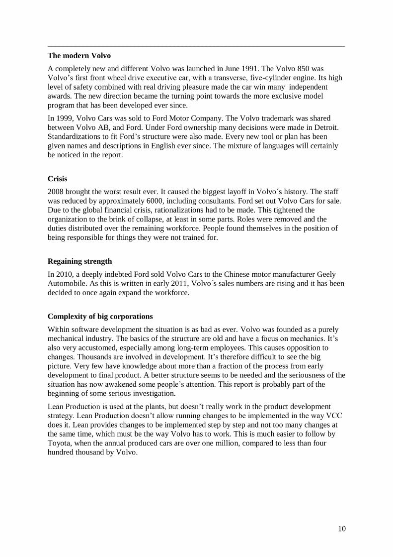
The introduction of building cars with CAN also made it possible to develop a lot of
functions that car builders never thought of before, therefore the cable length did not decrease
as it was meant to do at first. Figure 4.1 shows the development of the number of fuses and
cable lengths in a Volvo car during the past 80 years. (Olof Hansson, VCC)
Figure 4.1: Number of fuses and cable length in meters for the past 80 years
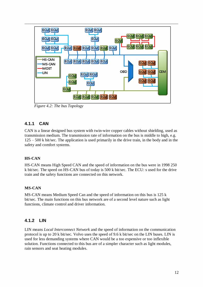
4.1 The different network buses
The electrical system is built on three to four different network buses for data transfer
between nodes, depending on the functional content of the car. The network buses are
interconnected to each other by the CEM and the OBD, On Board Diagnostics. The OBD is
the module used to download the software in the car and to analyze the car, for example
before doing service. The three different network buses are CAN (HS-CAN, MS-CAN), LIN,
Local Interconnect Network, and MOST, Media Oriented System Transport, and are
connected to the ECU: s like in figure 4.2.
___________________________________________________________________________
12
Figure 4.2: The bus Topology
4.1.1 CAN
CAN is a linear designed bus system with twin-wire copper cables without shielding, used as
transmission medium. The transmission rate of information on the bus is middle to high, e.g.
125 – 500 k bit/sec. The application is used primarily in the drive train, in the body and in the
safety and comfort systems.
HS-CAN
HS-CAN means High Speed CAN and the speed of information on the bus were in 1998 250
k bit/sec. The speed on HS-CAN bus of today is 500 k bit/sec. The ECU: s used for the drive
train and the safety functions are connected on this network.
MS-CAN
MS-CAN means Medium Speed Can and the speed of information on this bus is 125 k
bit/sec. The main functions on this bus network are of a second level nature such as light
functions, climate control and driver information.
4.1.2 LIN
LIN means Local Interconnect Network and the speed of information on the communication
protocol is up to 20 k bit/sec. Volvo uses the speed of 9.6 k bit/sec on the LIN buses. LIN is
used for less demanding systems where CAN would be a too expensive or too inflexible
solution. Functions connected to this bus are of a simpler character such as light modules,
rain sensors and seat heating modules.

___________________________________________________________________________
13
4.1.3 MOST
MOST means Media Oriented System Transport and is a communication protocol for
systems with high demands on data transfer. The functions carried out with MOST
connection are the multimedia components in the car, such as Bluetooth phone module,
integrated audio module and the multimedia module. This network differs from the others
being an optical fiber network carrying information much faster than the others, about 25 M
bit/sec, but it is also much more expensive than the other networks. The network uses master-
slave architecture.
4.2 Number of ECUs the past decade
To understand the difficulty of implementing functions in a car, a review of the development
over the past decade is going to be described.
Figure 4.3: Trend of the development of number of nodes the past decade
With the launch of the S80 in 1998, the car had 20 nodes connected to the CAN buses. In
2002, the XC90 was introduced to the market built on the same platform as the S80, but now
containing almost twice as many nodes, 39 pieces. In 2003 a new platform was introduced,
including the S40, and now the amount of nodes was 49 pieces. With the introduction of the
new S80 in 2006, the number of nodes included in the car was 69 pieces. The newest
launched S60 includes 77 nodes. As described, the number of nodes is always increasing due
to the expectations upon the final client of the car. The final client has more and more
demands on the functionality of the car. Therefore the development of new functions will
demand more and more nodes implemented on the car market.
0
10
20
30
40
50
60
70
80
90
100
1998 S80
2002 XC90
2006 S80N
2010 S60
2014
Number of nodes

___________________________________________________________________________
14
4.3 Difficulties to implement a function
To return to the example of the lock function on the car, which was mentioned earlier, this
requires the involvement of three nodes to implement the function "lock the car". The groups
of nodes then have to cooperate with each other to carry out the whole function. In this way
lots of nodes are involved in lots of functions, and the work implementing all those functions
requires well organized work. All teams know to follow GPDS, but running changes
demanded during projects makes it almost impossible to follow. Running changes requires
starting over, almost from the beginning. This is very often caused by new hardware and is
one of the biggest reasons why software is delivered too late.
Figure 4.4: The trend of required amount of software in MB
Running changes sometimes requires that the existing SDB, Signal Database, must be
changed. A new node must be connected or an existing node must get a new or another
connection. These changes can then affect already completed developed software, which then
must be re-developed again to suit the new SDB, Signal Database.
0
5
10
15
20
25
30
35
1998 S80
2002 XC90
2006 S80N
2010 S60
2014
Downloaded software size
in MB
Figure 4.5: A new node
requires changes in the
SDB, Signal Database
___________________________________________________________________________
15
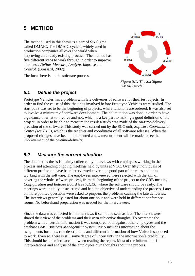
5 METHOD
The method used in this thesis is a part of Six Sigma
called DMAIC. The DMAIC cycle is widely used in
production companies all over the world when
improving an already existing process. The method has
five different steps to work through in order to improve
a process. Define, Measure, Analyze, Improve and
Control. (Brassard, 2002).
The focus here is on the software process.
5.1 Define the project
Prototype Vehicles has a problem with late deliveries of software for their test objects. In
order to find the cause of this, the units involved before Prototype Vehicles were studied. The
start point was set to be the beginning of projects, where functions are ordered. It was also set
to involve a minimum of hardware development. The delimitation was done in order to have
a guidance of what to involve and not, which is a key part to making a good definition of the
project. In order to be able to measure the result a study was made of the on-time-delivery
precision of the software. This study was carried out by the SCC unit, Software Coordination
Center (see 7.1.5), which is the receiver and coordinator of all software releases. When the
proposed changes have been implemented a new measurement will be made to see the
improvement of the on-time-delivery.
5.2 Measure the current situation
The data in this thesis is mainly collected by interviews with employees working in the
process and attending ongoing meetings held by units at VCC. Over fifty individuals of
different profession have been interviewed covering a good part of the roles and units
working with the software. The employees interviewed were selected with the aim of
covering the whole software process, from the beginning of the project to the CRB meeting,
Configuration and Release Board (see 7.1.13), where the software should be ready. The
meetings were initially unstructured and had the objective of understanding the process. Later
on more pointed questions were asked to pinpoint the problems causing the late deliveries.
The interviews generally lasted for about one hour and were held in different conference
rooms. No beforehand preparation was needed for the interviewees.
Since the data was collected from interviews it cannot be seen as fact. The interviewees
shared their view of the problems and their own subjective thoughts. To overcome the
problem with uncertain information it was compared both against other employees and the
database BMS, Business Management System. BMS includes information about the
assignments for units, role descriptions and different information of how Volvo is supposed
to work. Even so, there is still some degree of uncertainty in the information´s credibility.
This should be taken into account when reading the report. Most of the information is
interpretations and analysis of the employees own thoughts about the process.
Figure 5.1: The Six Sigma
DMAIC model
___________________________________________________________________________
16
The reason for doing so many interviews was to get first hand information from the people
working with the process. Reading a piece of paper about how they should work is not the
same as collecting information about how they are actually working. The best way to
understand the problems in the process is to ask the people that actually work with it.
Based on the information from the interviews with the employees and observations of Volvo
meetings the following work was carried out:
A flowchart showing the current process was developed in order to understand how
the process works and what needs to be improved. The flowchart was made in the
program Visio which is used at VCC to develop flowcharts. To make sure the
flowchart was correct it was shown to several people working in different parts of the
process.
A unit report was created to structure the information and get a wider understanding
of the units developing the software. The unit report is designed to answers the
questions: What is the assignment of the unit? What is the problem in the unit? What
problems in the unit are caused by other units? What problems affect the following
units?
To certify the correctness of the unit report and the flowcharts, a verification against
Volvo‟s database BMS was carried out.
5.3 Analyze to identify causes
With all the problems reported during the interviews and seen during the participation of the
VCC meetings, a sorting of the problems was made. The problems which caused the most
negative effect to the on-time-delivery, and were most certain, were put into a problem list
(see chapter 10). The list answers the questions: What is the problem? How can we solve this
problem? The problems were then put into groups with the same root cause: Structure,
Communication, Tools and system, General problems and Other problems.
After going through the problems and understanding the causes of them, an evaluation of the
units were made. The unit which had the most negative effect on the on-time-delivery of
software was pointed out to be further investigated.
Then a series of interviews with the chiefs of the unit concerned were made to figure out
what their problems are and what can be done to solve them. Ten managers from the unit
were interviewed, four with a high on-time-delivery rate and six with a low on-time-delivery
rate. The sorting of managers with high and low on-time-deliveries was done in order to
figure out the difference between the two groups. The interviews were agreed in advanced
and organized in the same way for all of the interviewees. The meetings were well structured
with seventeen pre decided questions and a self assessment form to fill out. The questions
varied from planning, communication, dealing with supplier and organization. The self
assessment form involved ten claims which the interviewees rated on a scale from 0-10
depending on if they agreed or not. The claims focused on the same categories as the
questions. Both the questions and the self assessment form were created after going through
the problems gathered during the fifty first interviews. The questions asked can be seen in
Appendix A1 and the self assessment form in Appendix A2.
___________________________________________________________________________
17
Literature studies
After understanding the biggest problems a literature study was made to understand the
problems better and to figure out solutions. Three books were read and are presented in the
theoretical framework (chapter 2) and in the analysis chapter.
Analysis
An analysis of the theoretical framework is done in chapter 9 where the theory is compared
to the problems found.
5.4 Improve
For some of the problems in the problem list suggested solutions were added, others were just
highlighted without any solution, with the intention of enlightening VCC of their existence.
A new improved flowchart was made taking the problems and solution suggestions into
consideration.
Solutions were developed in two ways:
Interviews with employees who work in the process and have knowledge about
different problems in their unit
Brainstorming
5.5 Control
After implementation a new study will be made to see if the on-time delivery precision has
improved.

___________________________________________________________________________
18
6 FUNCTION IMPLEMENTATION
This chapter will describe the software part of the Product Development process used by
Volvo. First the GPDS plan will be described as well as the C-note, Change-note, a tool used
within PD. Then a simplified process map will be presented and explained with focus on
function implementation.
6.1 GPDS, Global Product Development System
The product development system used at VCC is developed by Ford and Volvo with
benchmarking at Mazda. The plan is named GPDS and is a compressed plan implemented in
2006 including the best parts from the three companies to minimize the time of development.
The plan points out all the milestones for the projects to follow during the process.
The longest time required to develop a complete new product is about 50 months. The
electronics product development is done in three departments: Chassis, Powertrain and
EESE, Electrical and Electronics Systems Engineering. EESEs‟ part of the plan in major
projects is about 46 months and is named EESE GPDS plan. This includes five E-series, E0
to E4, for software deliveries to be final. The software articles are released at the CRB
meetings before being downloaded to the prototypes.
The delivered software to the E-series is used to test the functionality on Boxcars, which
means that the entire electric system is built on a table (see 7.1.8). The GPDS plan also
includes six additional prototype series, XO, X1, M1, VP, TT and PP. Those series are built
up as mules i.e. in already existing car models that have been modified for system
development. Most often those series are represented by Boxcars as well.
According to the delimitations of this project the focus is to involve only the M1 and VP
series. This chapter will primarily describe the process for software deliveries to those series.
The GPDS plan includes milestones and figure 6.1 shows only the important milestones for
the software deadlines to those series.
6.2 C-note, Change note
When a project is to be started, C-notes are used to describe how a change from an existing
car is going to be. There is one C-note created for each node involved in the project and it
includes descriptions of all the software and hardware articles.
___________________________________________________________________________
19
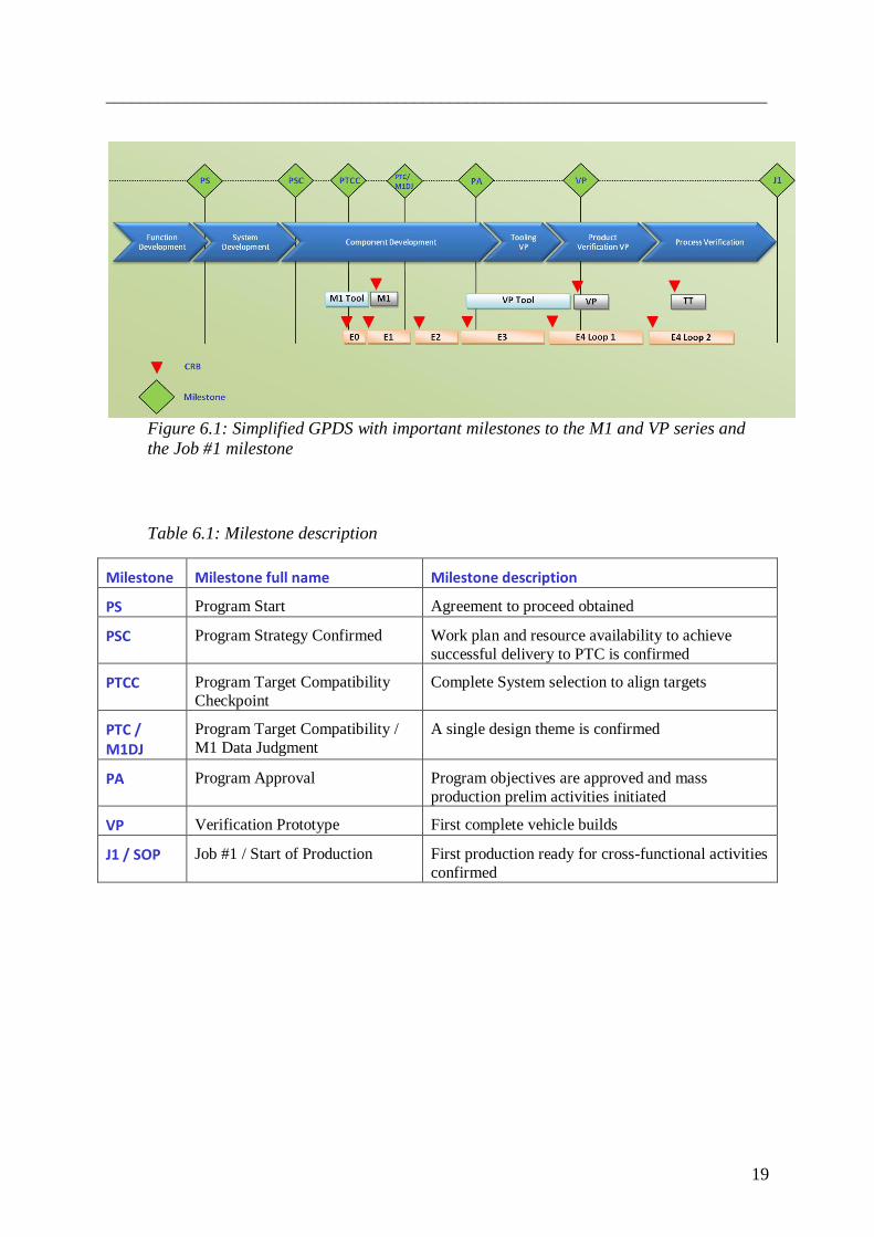
Figure 6.1: Simplified GPDS with important milestones to the M1 and VP series and
the Job #1 milestone
Table 6.1: Milestone description
Milestone Milestone full name Milestone description
PS Program Start Agreement to proceed obtained
PSC Program Strategy Confirmed Work plan and resource availability to achieve
successful delivery to PTC is confirmed
PTCC Program Target Compatibility
Checkpoint
Complete System selection to align targets
PTC / M1DJ
Program Target Compatibility /
M1 Data Judgment
A single design theme is confirmed
PA Program Approval Program objectives are approved and mass
production prelim activities initiated
VP Verification Prototype First complete vehicle builds
J1 / SOP Job #1 / Start of Production First production ready for cross-functional activities
confirmed

___________________________________________________________________________
20
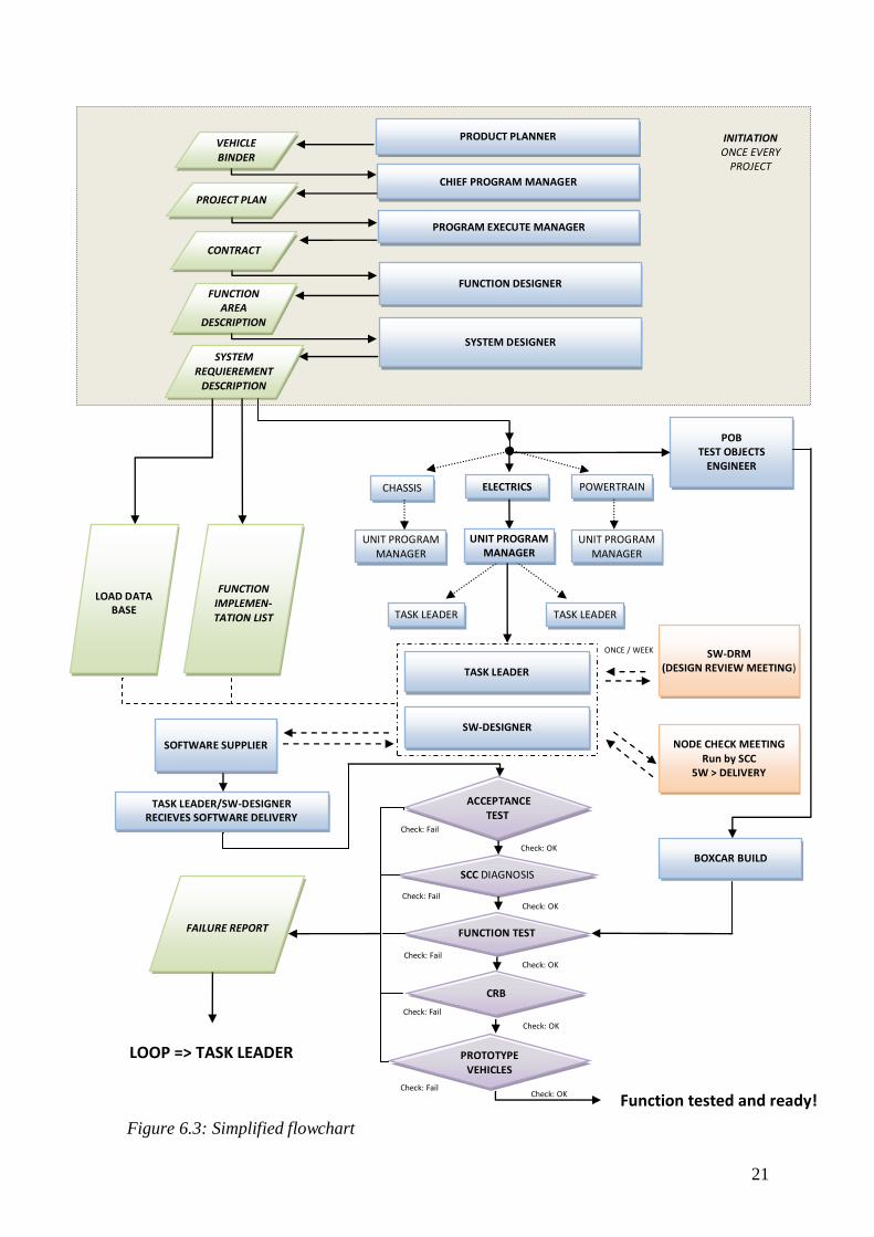
6.3 Simplified process flow
The following map (figure 6.3) focuses on function implementation. The intention is to show
how projects are initiated and distributed over a branch of units. They are all involved in
carrying out a function – in this case developed by the electrics unit. The map ends with a
successful test of the function.
In the initiation phase the project is planned and a framework for construction is set. All
functions are specified and later described in detail. For instance, the system designer
specifies the interface of communication etc. in the SRD, System Requirement Description.
When this is completed the project passes a gate called PS, Program Start. Based on the SRD
the project starts up in full scale. The document is passed on to all involved units.
Symbols
Document or
database
Event involving unit
or role
Test and
decision
Roles closely
connected or filled by
one individual
Task completed and passed on
to the next unit
Communication between units
Link between unit and database
Meeting
Figure 6.2: Descriptions of Symbols to the Simplified flowchart
___________________________________________________________________________
21
Check: OK
Check: OK
ONCE / WEEK
PRODUCT PLANNER
TASK LEADER TASK LEADER
TASK LEADER/SW-DESIGNER RECIEVES SOFTWARE DELIVERY
SW-DRM
(DESIGN REVIEW MEETING)
NODE CHECK MEETING Run by SCC
5W > DELIVERY
SOFTWARE SUPPLIER
CHIEF PROGRAM MANAGER
UNIT PROGRAM MANAGER
CHASSIS ELECTRICS POWERTRAIN
SYSTEM DESIGNER
PROGRAM EXECUTE MANAGER
FUNCTION DESIGNER
BOXCAR BUILD
Function tested and ready!
Check: OK
Check: Fail
ACCEPTANCE TEST
Check: OK
Check: Fail
Check: Fail
TASK LEADER
PROTOTYPE VEHICLES
FAILURE REPORT
LOOP => TASK LEADER
SW-DESIGNER
POB TEST OBJECTS
ENGINEER
SCC DIAGNOSIS
UNIT PROGRAM MANAGER
UNIT PROGRAM MANAGER
INITIATION ONCE EVERY
PROJECT
PROJECT PLAN
VEHICLE BINDER
CONTRACT
FUNCTION AREA
DESCRIPTION
FUNCTION IMPLEMEN-TATION LIST
SYSTEM REQUIEREMENT
DESCRIPTION
FUNCTION TEST
CRB
Check: Fail
Check: Fail
Check: OK
LOAD DATA BASE
Figure 6.3: Simplified flowchart

___________________________________________________________________________
22
6.4 Map explanation
PRODUCT PLANNER: Decision is made to develop a new model.
VEHICLE BINDER: Basic required specifications such as colors or
surround sound.
CHIEF PROGRAM MANAGER: Delivers programs to agreed objectives.
PROJECT PLAN: GPDS (Global Product
Development System).: Generic plan including every aspect of the
development. Includes deadlines etc.
PROGRAM EXECUTE MANAGER: Manages the industrial development and
deliveries a vehicle program according to GPDS
CONTRACT: The project signs a contract with the line
organization which handles economic means.
FUNCTION DESIGNER: Creates a list FAD, Function area description of
all functions in the car.
FUNCTION AREA DESCRIPTION: FAD can be seen as an initial form of a Drivers Owner‟s Manual to explain how car
functions/features are supposed to be working
and used but not how they are technically implemented.
SYSTEM DESIGNER: The System Designer develops and maintains electrical systems solutions based on the FAD.
All functions are specified and later described in
detail. The System Designer specifies the
interface of communication etc.
SYSTEM REQUIEREMENT
DESCRIPTION: Specified list of demands on parts and functions.
UNIT PROGRAM MANAGER: Determines activities to complete the unit's total
commitments.
TASK LEADER: Responsible for realization of the functionality in
their corresponding node.
SW-DESIGNER: Handles software development for a node.
Communicates with suppliers, adjusts the
software to fit the car and orders testing.
SOFTWARE SUPPLIER: For instance Bosch who has a big cart of sub-
systems for cars.
SW-DRM (DESIGN REVIEW MEETING): Once a week SCC organizes a meeting where software designers are invited due to issues
affecting their corresponding node.
NODE CHECK MEETING: Five weeks before delivery deadline SCC calls all
Software Designers scheduled to deliver. The
question is “What will you be able to deliver?”
ACCEPTANCE TEST: A test to verify basic functionality. Does the node
communicate at all?
SCC DIAGNOSIS: Before being added to the database KDP, files
and documentation are manually checked for
flaws and mistakes.
FUNCTIONALITY TEST
Further testing conducted in boxcars, equipped
with the hardware that the software is intended to
control.
CRB
Final meeting where decision is made whether to
release the software or not. Are the tests satisfactory, documentation complete etc?
PROTOTYPE VEHICLES: Prototype vehicles conducts testing of cars in different situations and environments.
FAILURE REPORT: If a system fails, this is documented and an extra
loop starts.
TEST OBJECTS ENGINEER: Orders hardware necessary for each test object
ID.
LOAD DATA BASE: Contains information about wiring etc.
FUNCTION IMPLEMENTATION LIST: FIP is updated by contact with the software designers. It indicates which function is supposed
to be ready at a given time – e.g. ready to which
series.
___________________________________________________________________________
23
7 THE CURRENT SOFTWARE PROCESS
This chapter will describe the current software process all the way through the different units
and functions. It also presents the way the software development goes to become a final
product to be downloaded into the car or the test object. Problems affecting the units,
problems within the units as well as problems affecting the next unit will be described. Then
the chapter is visualized to get an idea of the connections.
7.1 Treated areas within the process
The departments within VCC which manage the software have been divided into:
1) units / role, 2) role and 3) tool / meeting.
The division units / role describe primarily the assignment by a role within a unit/department
and secondary the problems within and around it. When the software management is a part of
a role, the description is divided just into role; this means that the overall task within the role
isn‟t just software management but only the software management is described. The third
division presented is tool / meeting and describes just the tools and meetings required by the
role or unit to manage the software development.
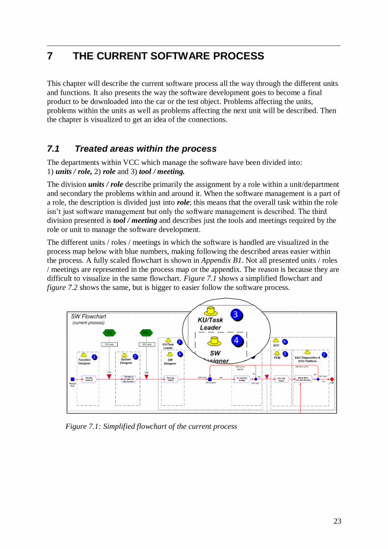
The different units / roles / meetings in which the software is handled are visualized in the
process map below with blue numbers, making following the described areas easier within
the process. A fully scaled flowchart is shown in Appendix B1. Not all presented units / roles
/ meetings are represented in the process map or the appendix. The reason is because they are
difficult to visualize in the same flowchart. Figure 7.1 shows a simplified flowchart and
figure 7.2 shows the same, but is bigger to easier follow the software process.
Figure 7.1: Simplified flowchart of the current process

___________________________________________________________________________
24
Figure 7.2: Simplified software flowchart of the current process
___________________________________________________________________________
25
Each mentioned area will describe the unit‟s:
Assignment
Problems caused by other units (prior units)
Accumulated problems in prior units
Problems within the unit
Problems affecting other units
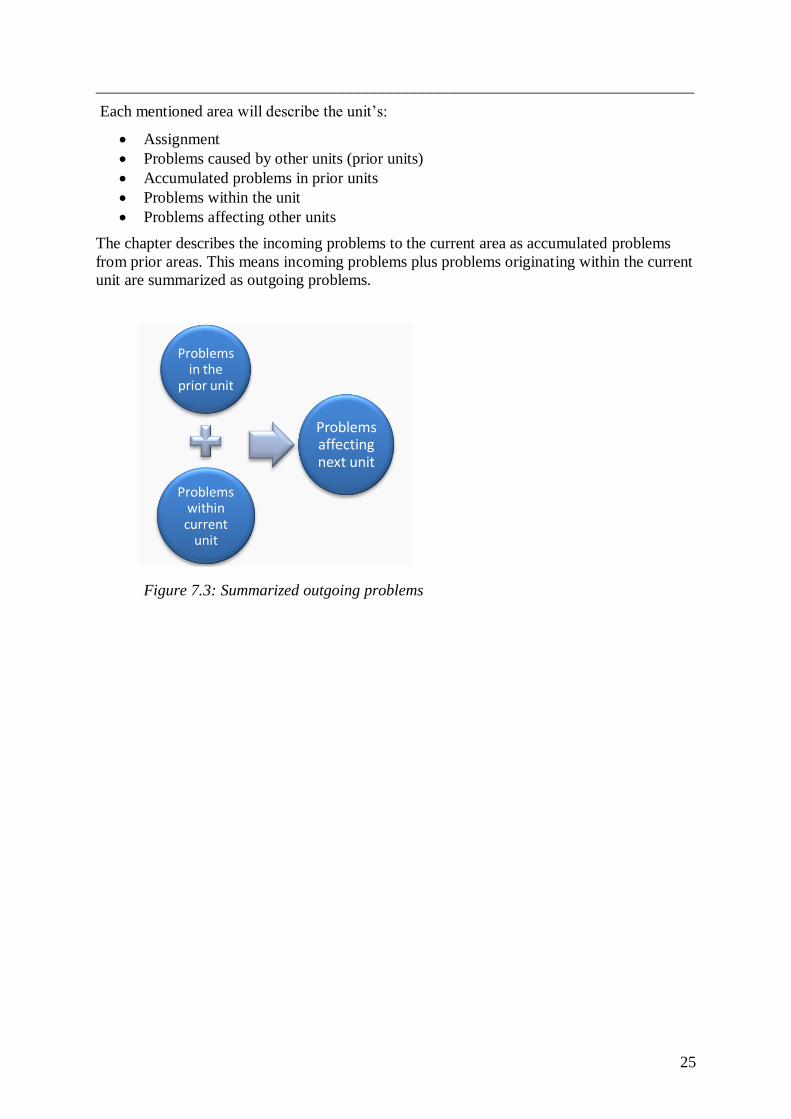
The chapter describes the incoming problems to the current area as accumulated problems
from prior areas. This means incoming problems plus problems originating within the current
unit are summarized as outgoing problems.
Problems in the
prior unit
Problems within current
unit
Problems affecting next unit
Figure 7.3: Summarized outgoing problems

___________________________________________________________________________
26
1 7.1.1 Unit / Role: Function Designer
Assignment:
To create a list of all the electric functions in the car. For each assigned feature a FAD,
Function Area Description is created. The FAD document is used to describe and specify the
behavior and functional requirements of the functions/features within a function area. The
FAD can in many cases be seen as an initial form of a Driver‟s Owner Manual explaining
how the car‟s functions/features are supposed to be working and used but not how they are
technically implemented. The described features are often structured according to the
principle of action (e.g. push button) – a function is activated (e.g. the car´s central locking is
activated).
The Function Designer is responsible for constructing a detailed design- and simulation
model used to validate the functional areas with the help of the Purpose of Series Document
(see 7.1.15). This model is used by the Task Leader to find out what must be finished to each
series, in order to be tested. The information will then be posted to the FIP, Function
Implementation Plan (see 7.1.14). Other tasks are to manage deviations from the function
constructer and to participate in reviewing the SRD.
Problems caused by other units:
The client (the project) gives vague and/or late information about which functions
should be implemented. There are often new requirements during the project.
Problems within the unit:
It can be difficult to meet the deadlines due to running changes.
The function designer doesn‟t check if the Task Leaders have the capacity to make the
deliveries for the different series in time.
Purpose of Series Document is not used as much as it should be, because of the vague
descriptions in it.
Doesn‟t have knowledge of which hardware is available for each series.
Problems affecting other units:
It often takes more time than intended to produce a FAD. The following parts in the
project are then forced to do their job in shorter time to keep their deadlines.
The FAD can be interpreted in several ways and can be unclear for subsequent units
and has no feedback during the project. The system designer is primarily affected.
The Function Designer puts too high demands on the implementation of the functions
for the different E-series which affect the Task Leader.

___________________________________________________________________________
27
2 7.1.2 Unit / Role: System Designer
Assignment:
Based on the FAD, create a comprehensive system solution, a SRD. The SRD should contain:
Which hardware components are required
Which software is required and which ECU:s are involved
The System Designer‟s responsibility is also to ensure that the system solution will be
verified.
Problems caused by other units:
Function designer: The FAD is often delayed and sometimes vague and open to
interpretation when the SRD is developed.
Accumulated problems in prior units:
The client (the project) gives vague and/or late information about which functions
should be implemented. There are often new requirements during the project.
Problems within the unit:
The SRD has not been signed off with the FAD, which can create problems later on when the
SRD must be changed when discovering that the FADs demands are not met in the SRD.
Problems affecting other units:
The SRD can be interpreted in several ways; it‟s sometimes unclear for subsequent units. The
System Designer is not getting/giving any feedback during the project.

___________________________________________________________________________
28
4 7.1.3 Unit / Role: Software Designer
Assignment:
Develop a SWRS, Software Requirement Specification, from the SRD. The SWRS‟s
functional requirement is based on allocated system requirements from the model of
Elektra (normal procedure).
Distribute feedback to the FIP Status Report.
Responsible for ensuring that the software is verified by writing a test order to an
acceptance tester (SW-tests) and an integration tester.
Participate at NCM, Node Check meeting, and SW-DRM, Software Design Review
Meeting (see 7.1.12) when called.
Problems caused by other units:
SW suppliers are not finished in time for deadlines and software is not good enough.
System designer: SRD is often vague and finished too late. When creating a SWRS,
a personal interpretation of the SRD is often used.
Accumulated problems in prior units:
Function designer: The FAD is often delayed and sometimes vague and open to
interpretation when the SRD is developed.
The client (the project) gives vague and/or late information about which functions
should be implemented. There are often new requirements during the project.
Problems within the unit:
Demands to software supplier are not clear enough. Some Software Designers do not
send part deadlines (for E-series) to the supplier. Suppliers just send what is finished
so far when it is time to deliver to the different series.
When the supplier misses a deadline or mismanages there is very little VCC can do to
put pressure on them. Volvo is seen as a small customer and isn't as important as e.g.
Ford.
Poor communication between Software Designers, which creates problems due to
strong dependence between one another.
Software Designers have to break down the FIP to node level on their own. This
causes problems because it becomes a matter of interpretation.
Software Designers just see the different software deliveries and not to the function.
They don't see the whole picture (the function). This is shown in table 7.1. This is due
to poor communication between Software Designers or Task Leaders and the FIP.
Poor communication and control between Software Designers and Function Designers
when checking if the ordered function is correctly implemented.
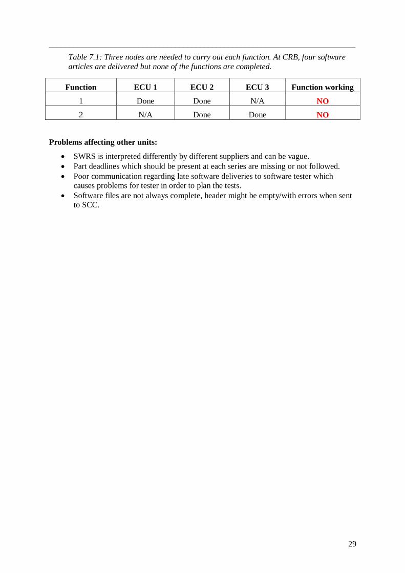
___________________________________________________________________________
29
Table 7.1: Three nodes are needed to carry out each function. At CRB, four software
articles are delivered but none of the functions are completed.
Function ECU 1 ECU 2 ECU 3 Function working
1 Done Done N/A NO
2 N/A Done Done NO
Problems affecting other units:
SWRS is interpreted differently by different suppliers and can be vague.
Part deadlines which should be present at each series are missing or not followed.
Poor communication regarding late software deliveries to software tester which
causes problems for tester in order to plan the tests.
Software files are not always complete, header might be empty/with errors when sent
to SCC.

___________________________________________________________________________
30
5 7.1.4 Unit / Role: Software Tester / Acceptance test
Assignment:
The acceptance tester performs testing of the basic features and of the software,
approximately 10 % of the total tests is done here. The tests are performed on a rig and the
tester controls that basic functions are safe and not likely to disrupt the network when
connected to the other nodes i.e. common system communication problems is to be found.
Problems caused by other units:
Task Leader: Delayed software delivery and/or poor quality of the software. Part
deadlines are missing or not followed.
POB, Provobjektsberedare (7.1.7): Delayed hardware deliveries and/or poor
hardware quality
Accumulated problems in prior units:
SW suppliers are not finished in time for deadlines and software is not good enough.
System designer: SRD is often vague and finished too late. When creating a SWRS a
personal interpretation of the SRD is often used.
Function designer: The FAD is often delayed and sometimes vague and open to
interpretation when the SRD is developed.
The client (the project) gives vague and/or late information about which functions
should be implemented. There are often new requirements during the project.
Problems within the unit:
Due to time constraint, acceptance tests at Volvo are sometimes skipped. Tests done by the
supplier are then accepted as sufficient.
The hardware needed for the tests is sometimes missing. In those cases old hardware must be
used and may not be reliable.
There is lack of structure of what should be tested. It depends on the experience of the tester
and the tests vary a lot from different testers.
Problems affecting other units:
The acceptance tests are delayed and do not provide sufficient information about whether the
software is good enough.
Since only 10% of the software is tested, the risk of software defects in the integration and
function tests are high.

___________________________________________________________________________
31
6 7.1.5 Unit / Role: SCC, Software Coordination Center / PCM,
Program Control Manager
Assignment PCM:
Check if the software deliveries from Task Leaders have the correct format and
documentation.
Initiate integration tests through the tool eTracker.
Organize and manage the CRB meetings which are preceded by the NCM and SW-
DRM.
Release software to SW Archive (see 7.1.5.1) and make software files available in
SW Configuration (see 7.1.5.1).
The SCC department is responsible for the NCM, which is held about five weeks
before CRB, and SW-DRM which is a weekly meeting.
Problems caused by other units, according to the SCC team:
Software Designer or Task Leader cannot deliver software in time, i.e. to the MRD
milestone, Material Required Date.
The C-notes are incomplete and not ready in time.
The test order consists of wrong information, e.g. hardware id-code.
Redeliveries of software generate twice as much work.
Hardware is missing in the boxcar, or does not match the intended test due to changes
made after the POB unit ordered the hardware.
Capacity problems due to that the systems are not coordinated in terms of time
management and also due to lack of coordination between different projects.
Received files have incorrect format and/or insufficient documentation.
Delayed software deliveries and poor prior information about it.
Other problems:
Task Leader: Delayed software delivery and/or poor quality of the software. Part
deadlines are missing or not followed.
Accumulated problems in prior units:
Acceptance test: Is sometimes not done or not sufficient.
POB: Delayed hardware deliveries and/or poor hardware quality.
SW suppliers: are not finished in time for deadlines and software is not good enough.
System designer: SRD is often vague and finished too late. When creating a SWRS a
personal interpretation of the SRD is often used.
Function designer: The FAD is often delayed and sometimes vague and open to
interpretation when the SRD is developed.
The client (the project) gives vague and/or late information about which functions
should be implemented. There are often new requirements during the project.

___________________________________________________________________________
32
Problems within the unit:
Lack of IT-systems requires manual handling which gives a potential for failure (human
factor). Lotus Notes (see 7.1.5.1) is outdated and there is no synchronization with SW
Archive. Documentation must be done manually in Excel documents. This can be difficult to
survey. The automatic orders are first used at the VP series, which leads to a lot of manual
work on the prior series and the risk of failure is high. KDP is first used in the VP series i.e.
only in the cars built on the following Target Plants: VCT in Torslanda, VCG in Gent and
PFS in Uddevalla.
When a Task Leader misses a deadline there is not much the SCC team can do, they lack
power.
Problems affecting other units:
Mistakes in manual handling can result in incorrect documentation and file placement which
creates problems mainly to the Function and Integration team (verification team).
Delayed software and poor information about it can cause big problems.
7.1.5.1 SCCs management of software against product at VCC:
SW Configuration is a database where software for each constructed series is specified. All
software used for assembly is uploaded here, as well as software updates between the series.
Updated parts get the same article number but a new “version number” (letters) is included.
SW Archive is a database where software for assembly in Target Plant is stored. SW Archive
cannot handle articles with version numbers; it means that every updated article must obtain a
totally new article number.
VIDA, the aftermarket system, can read the software context in cars built in series from TT
and forward, but not from the VP series which are built in the target plant. This causes
problems when mules in the M1 series are built using VP donor vehicle built in the Target
Plant or an old M1 built on Pilot Plant.
Figure 7.4: Illustration of the software articles management
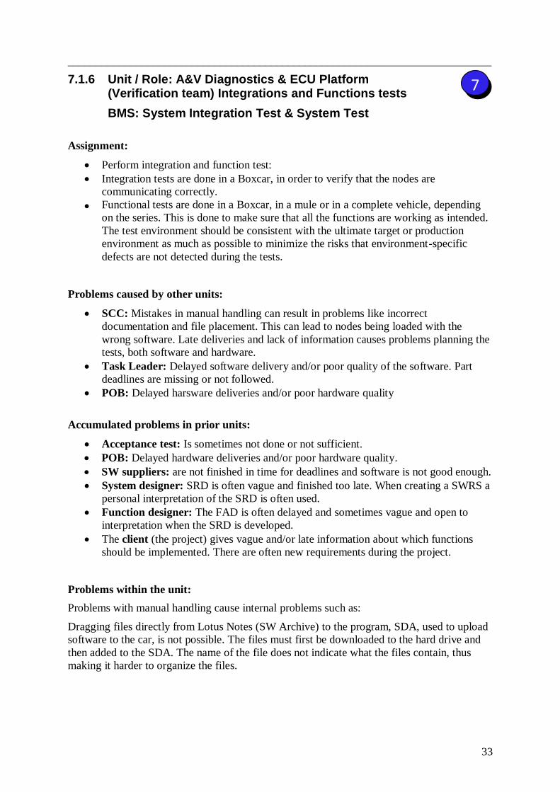
___________________________________________________________________________
33
7 7.1.6 Unit / Role: A&V Diagnostics & ECU Platform (Verification team) Integrations and Functions tests
BMS: System Integration Test & System Test
Assignment:
Perform integration and function test:
Integration tests are done in a Boxcar, in order to verify that the nodes are
communicating correctly.
Functional tests are done in a Boxcar, in a mule or in a complete vehicle, depending
on the series. This is done to make sure that all the functions are working as intended.
The test environment should be consistent with the ultimate target or production
environment as much as possible to minimize the risks that environment-specific
defects are not detected during the tests.
Problems caused by other units:
SCC: Mistakes in manual handling can result in problems like incorrect
documentation and file placement. This can lead to nodes being loaded with the
wrong software. Late deliveries and lack of information causes problems planning the
tests, both software and hardware.
Task Leader: Delayed software delivery and/or poor quality of the software. Part
deadlines are missing or not followed.
POB: Delayed harsware deliveries and/or poor hardware quality
Accumulated problems in prior units:
Acceptance test: Is sometimes not done or not sufficient.
POB: Delayed hardware deliveries and/or poor hardware quality.
SW suppliers: are not finished in time for deadlines and software is not good enough.
System designer: SRD is often vague and finished too late. When creating a SWRS a
personal interpretation of the SRD is often used.
Function designer: The FAD is often delayed and sometimes vague and open to
interpretation when the SRD is developed.
The client (the project) gives vague and/or late information about which functions
should be implemented. There are often new requirements during the project.
Problems within the unit:
Problems with manual handling cause internal problems such as:
Dragging files directly from Lotus Notes (SW Archive) to the program, SDA, used to upload
software to the car, is not possible. The files must first be downloaded to the hard drive and
then added to the SDA. The name of the file does not indicate what the files contain, thus
making it harder to organize the files.
___________________________________________________________________________
34
Problems affecting other units:
The integration and functional tests are delayed and do not give satisfactory results. In some
cases errors in the software are discovered too late to be fixed for the next series. This leads
to series passing without a chance to test the corrected software.
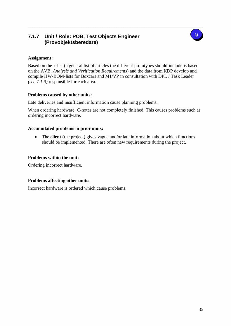
___________________________________________________________________________
35
9 7.1.7 Unit / Role: POB, Test Objects Engineer (Provobjektsberedare)
Assignment:
Based on the x-list (a general list of articles the different prototypes should include is based
on the AVB, Analysis and Verification Requirements) and the data from KDP develop and
compile HW-BOM-lists for Boxcars and M1/VP in consultation with DPL / Task Leader
(see 7.1.9) responsible for each area.
Problems caused by other units:
Late deliveries and insufficient information cause planning problems.
When ordering hardware, C-notes are not completely finished. This causes problems such as
ordering incorrect hardware.
Accumulated problems in prior units:
The client (the project) gives vague and/or late information about which functions
should be implemented. There are often new requirements during the project.
Problems within the unit:
Ordering incorrect hardware.
Problems affecting other units:
Incorrect hardware is ordered which cause problems.
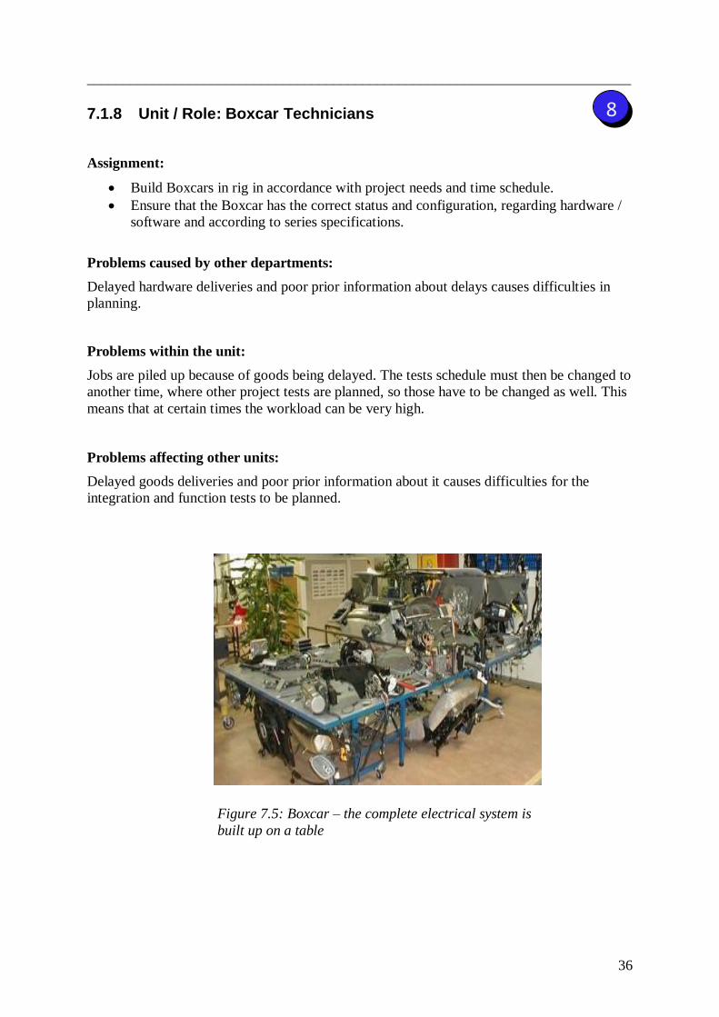
___________________________________________________________________________
36
8 7.1.8 Unit / Role: Boxcar Technicians
Assignment:
Build Boxcars in rig in accordance with project needs and time schedule.
Ensure that the Boxcar has the correct status and configuration, regarding hardware /
software and according to series specifications.
Problems caused by other departments:
Delayed hardware deliveries and poor prior information about delays causes difficulties in
planning.
Problems within the unit:
Jobs are piled up because of goods being delayed. The tests schedule must then be changed to
another time, where other project tests are planned, so those have to be changed as well. This
means that at certain times the workload can be very high.
Problems affecting other units:
Delayed goods deliveries and poor prior information about it causes difficulties for the
integration and function tests to be planned.
Figure 7.5: Boxcar – the complete electrical system is
built up on a table
___________________________________________________________________________
37
7.1.9 Role: UPM, Unit Program Manager at EESE
(DPL, Delprojektledare)
Role:
Assigned by the PEM, Program Engineer Manager, to operate and manage a product
development project towards set targets.
Follow decided structure, GPDS and applicable procedures of BMS.
Lead the cross-functional software work on behalf of the PEM within each project.
Manage SW-DRM which is a comprehensive Technical Project meeting.
Manage the construction of boxcar / HIL rig, Hardware In the Loop.
Manage and update the FIP.
Make decisions (approval / rejection) about releases of software articles in
consultation with the PCM to CRB.
Approve delivery plan for software and software deviations.
Decide on various software related issues, for example, planning Boxcar / HIL rig,
SDB changes, etc.
Monitor and report the software status (eTracker).
Problems:
Do not have sufficient understanding of the details in the process. A couple of years ago
there was a post called SU, Systemuppdragsledare, who had a closer role and more
understanding of the details in the process.
DPL should be tougher when someone misses a deadline.
DPL does not work according to the GPDS plan and BMS in its‟ fullness. This is accepted
but creates problems when employees think it is okay to not follow the plan.
DPL must accept running changes (orders) which cannot be carried out on time.
DPL should ensure that FIP is used more and is reported to on time.
There is no respect for SW-DRM which the DPL is responsible for and sometimes is the DPL
not even there.

___________________________________________________________________________
38
3 7.1.10 Role: Task Leader (KU, Konstruktionsuppdragsledare)
Role:
Manage a product development assignment for a specified component / subsystem toward its‟
target. The role can be established during PSC, Program Strategy Confirmed. The Task
Leader is responsible for the assignment from PTCC, Program Target Compatibility
Checkpoint, until FSR, Final Status Report.
The Task Leader has the responsibility for a PSS range, Product System Structure, or a
component or several components, depending on their severity. They have a Software
Designer who manages the software development.
Main Tasks:
Receive agreed order in forms of a TTC contract, Technology Target Compatibility,
and then industrialize the assignment in CDJ, Concept Data Judgment.
Manage the assignment through a cross functional team and ensure that all results and
deliveries are in accordance to the TTC contract.
Manage the project according to plan with a set task structure.
Develop, monitor and update relevant time plans for the current task.
Initiate and assure decisions, both in the project and in the line organization
(see figure 8.11), when deviations occur.
Communicate the project targets, commitments, status and forecasts in both internal
and external assignments.
Problems:
The Task Leader does not work according to the GPDS plan and BMS in its‟ fullness.
This is accepted but creates problems when employees think it is okay not to follow
the plan.
The C-note is created and established too late, which causes problems for SCC and
the building of Boxcar.
The Task Leader makes insufficient demands on the software suppliers. This provides
unclear orders that do not meet all deadlines. When the supplier misses a deadline or
doesn‟t agree with the Task leader the Task Leader lack measures to address.
Poor communication between Task Leaders which creates problems due to strong
dependence among each other.
The C-note is created too late and is not used for either the M1- or the E-series.
The Task Leader has to break down the FIP to node level by himself. This causes
problems because it becomes a question of interpretation.
Poor communication and control between Task Leaders and Function Designers when
checking if the ordered function is carried out correctly.
Late signing of contracts with the supplier cause late deliveries.
Demands on supplier are given first after the signing of contract, which cause delayed
software when the start of development is delayed.

___________________________________________________________________________
39
Realizing the functions is not number one priority. Software Designers just see to the
different software deliveries and not to the function. They don't see the whole picture (the
function). This is due to poor communication between Software Designers or Task Leaders
and possibly the FIP. See table 7.2 below.
Table 7.2: Three nodes are needed to carry out each function. At CRB there are four
software articles delivered, but none of the functions can be tested because two
software deliveries are missing.
Function ECU 1 ECU 2 ECU 3 Function working
1 Done Done N/A NO
2 N/A Done Done NO
___________________________________________________________________________
40
7.1.11 Tool / Meeting: TRM, Time Review Meeting
Assignment:
The TRM, Time Review Meeting is used as a reconciliation meeting between different
departments in a project. The meeting discusses and makes decisions regarding deviations for
series construction. TRM-forum starts at the beginning of the project and is conducted
through the whole project.
TRM provide the project management with information about late deliveries in order to
assess if the status level of the materials is sufficient to build the current series.
The units report at TRM deviations from the Purpose of Series Document and from the
specification for the current project.
Before the meeting:
The Task Leader reports deviation in the system Pre HPD, Handling of Parts Deviations,
before the TRM-meeting. The Task Leader anchors the deviation with the Analysis &
Verification Manager at each unit, and with responsible CME, Central Manufacturing
Engineer. Information is sent to the manager of Project Corporation. The meeting is held at
least every two weeks.
Meeting:
After response from the AVA, Analyze and Verification Responsible, and CME the
Test Leader can present the deviation for discussion in TRM.
The Project Planner sends a notice to the affected units.
TRM makes a decision about deviation.
The decision/order is noted in the system Pre HPD
Problems:
The meeting is insufficient to synchronize the entire project. Affected participants do not
always show up, which can lead to decisions being made without all affected people getting
the information. Software should be treated with the same importance as hardware.
___________________________________________________________________________
41
7.1.12 Tool / Meeting: SW-DRM & NCM
Assignment:
SW-DRM is a comprehensive Technical Project meeting for all the units. A forum to discuss
issues about the management, schedules, changes in software and SDB. After NCM the status
of project is discussed.
Node Check Meeting is a meeting to establish what software to test at the different series i.e.
what software should be delivered at the CRB meeting.
Contents of SW-DRM:
FIP, and deviations from FIP
Deviation reports
Changes in the SRD, which affect more than one node
Node changes affecting more than one node
NCM software deliveries
Planning and status of Boxcar
SDB issues
Diagnostic issues
Planning issues (software plan, check-up lists and software deliveries)
Testing Complete vehicle
Ongoing and aftermarket changes
SW-DRM has the responsibility and authority to take decisions regarding:
Approval of the software delivery plan.
Approval of deviations from SW-plan (from FIP and / or specific software-related
requirements)
The information presented and the decisions taken on the SW-DRM shall be communicated
to all staff in the technical project who is working with nodes software. SW-DRM documents
are available in Lotus Notes database TM94000.
Problems:
DPL isn‟t tough enough when someone misses a deadline.
There is no respect for SW-DRM which the DPL is responsible for and sometimes is the DPL
not even there.
The FIP isn‟t used enough by the Task Leaders and is just a forecast.
The meeting is insufficient to synchronize the entire project. Affected participants do not
always show up, which can lead to decisions being made without all affected people getting
the information.
The meetings have a potential that is not fully utilized by the Software Designers or Task
Leaders, who have little control over their own deliveries to respective series, according to
the SCC team.

___________________________________________________________________________
42
7.1.13 Tool / Meeting: CRB, Configuration & Release Board
Assignment:
The forum is used to approve and release software parts for the different series at least two
weeks before they are used.
Checked at CRB:
Testorder/CRB checklist
Acceptance test
Integration test
VIDA test
Information about compatibilities and next planned release
Problems:
The software isn't delivered in time or is not good enough.
DPL isn‟t tough enough when someone misses a deadline.
There is no respect for the deadlines at CRB which the DPL is responsible for and sometimes
is the DPL not even there.

___________________________________________________________________________
43
7.1.14 Tool / Meeting: FIP, Function Implementation Plan
Assignment:
An operation plan to work after, follow up and state deviations during the project in order to
get a problem free test object.
FIP describes:
What is planned to be implemented in each series.
When is it planned to be implemented.
Deviations from the plan.
The level of functionality to be included in each series (E-Series and X1, M1).
Problems:
FIP is a forecast but is often seen as fact. It could be used more if it were more reliable.
Do not get sufficient feedback from System Designers to update the FIP, the System
Designers in turn should receive updates from the Task Leaders (communication is not
working good enough across the stage).
Some Function Designers do not modulate in Elektra with the result that FIP cannot be
broken down to Node level. (This is the old way of doing it)
Powertrain and EESE do not interpret the FIP in the same way e.g. different understanding of
DI, Design Intent. EESE thinks that calibration should be included in DI and Powertrain does
not. This could be because Powertrain has a lot of calibration in their functions.
FIP is not broken down to node level which would make it easier for Task Leaders to know
what they have to deliver to each series.

___________________________________________________________________________
44
7.1.15 Tool / Meeting: Purpose of Series Document
Assignment:
A document that explains:
Why each series should be built
What should be finished in each series
What to test in each series
In order to test the functionality of the electrical components during development, a concept
for synchronizing deliveries was released. It is called E-series. Five series run parallel to the
other series, E0 - E4. For each series specific requirements should be adapted and make the
process more synchronized, this is included in the Purpose of Series Document.
Problems:
The document has never been fully developed and is open for interpretation. While some
Function Designers implements parts of the plan based on experience, others neglect its‟
existence. The result is less organized tests and testers who never know what to expect.
Therefore they cannot plan the testing as would be preferred.
Functions planned to be tested lack parts of the software needed to make the function work.
This is due to misunderstanding of what should be tested which should be in the Purpose of
Series Document.
The FIP isn‟t based on the Purpose of Series Document as it should.
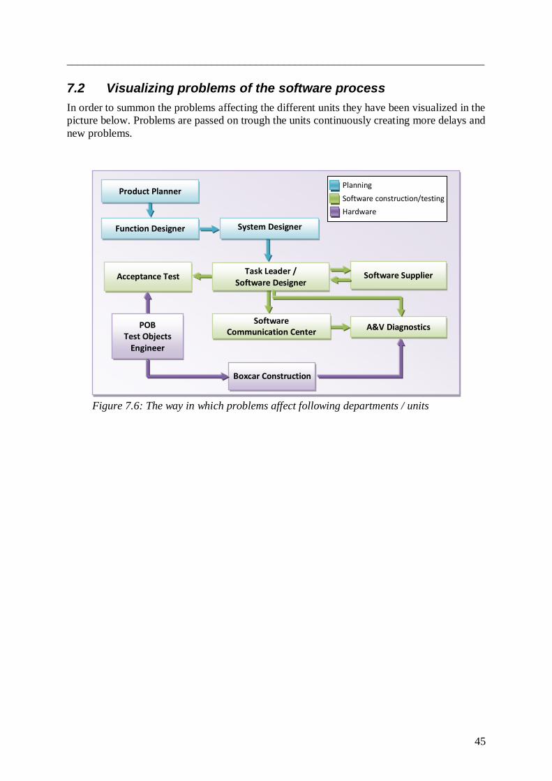
___________________________________________________________________________
45
7.2 Visualizing problems of the software process
In order to summon the problems affecting the different units they have been visualized in the
picture below. Problems are passed on trough the units continuously creating more delays and
new problems.
Planning
Software construction/testing
Hardware
Software Supplier
Function Designer
Boxcar Construction
Acceptance Test
A&V Diagnostics
System Designer
POB Test Objects
Engineer
Software Communication Center
Product Planner
Task Leader / Software Designer
Figure 7.6: The way in which problems affect following departments / units
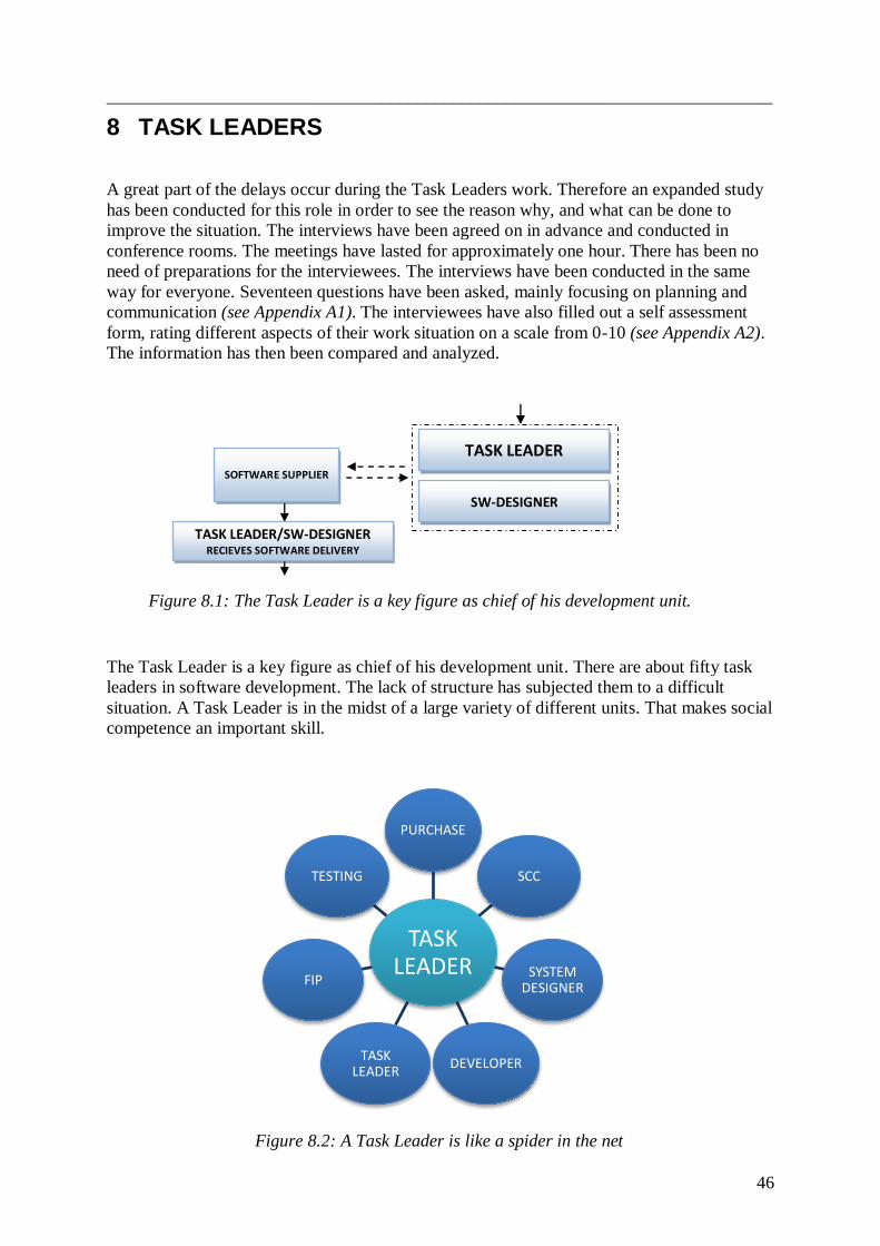
___________________________________________________________________________
46
8 TASK LEADERS
A great part of the delays occur during the Task Leaders work. Therefore an expanded study
has been conducted for this role in order to see the reason why, and what can be done to
improve the situation. The interviews have been agreed on in advance and conducted in
conference rooms. The meetings have lasted for approximately one hour. There has been no
need of preparations for the interviewees. The interviews have been conducted in the same
way for everyone. Seventeen questions have been asked, mainly focusing on planning and
communication (see Appendix A1). The interviewees have also filled out a self assessment
form, rating different aspects of their work situation on a scale from 0-10 (see Appendix A2).
The information has then been compared and analyzed.
The Task Leader is a key figure as chief of his development unit. There are about fifty task
leaders in software development. The lack of structure has subjected them to a difficult
situation. A Task Leader is in the midst of a large variety of different units. That makes social
competence an important skill.
Figure 8.2: A Task Leader is like a spider in the net
TASK LEADER
PURCHASE
SCC
SYSTEM DESIGNER
DEVELOPERTASK
LEADER
FIP
TESTING
TASK LEADER
SW-DESIGNER
TASK LEADER/SW-DESIGNER RECIEVES SOFTWARE DELIVERY
SOFTWARE SUPPLIER
Figure 8.1: The Task Leader is a key figure as chief of his development unit.

___________________________________________________________________________
47
The different Task Leaders and their units have differences in performance. The aim has been
to map up patterns. Delivery statistics have also been used to get a view of what factors are
the most important. There are many variables that are not reflected by statistics. With help of
people inside the organization, the goal has been to take these matters into account when
interpreting the information.
8.1 Indicators of performance
Software Coordination Center is the receiver of software before the releases. The unit has
statistics of the software deliveries. This data is of course non-disputable in the sense that it
reflects if an expected delivery is on time or not. The expectations are however, based on a
prognosis given by Software Designers at Node Check Meeting, five weeks before deadline.
8.1.1 MRD – Material Required Date
The graph illustrates the delivery precision for expected software. It shows the mean outcome
distributed over 100 days. The mean value is five days overdue. Software delivered late does
not have better functionality which otherwise could be a reason for the delay. Instead it
actually has less impressive performance according to statistics.
The top three reasons for the delays are said to be:
SRD is delayed and specifications unclear
Contracts with supplier are scheduled late
Running changes are made during projects
Figure 8.3: The delivery precision for expected software
0
10
20
30
40
50
60
70
MRD0 Software delivery differance (days)
MRD - Software deliveries over time
+60 MRD -40 Days
Delivered software

___________________________________________________________________________
48
8.1.2 Completeness of delivered software & documentation
An acceptance test is supposed to be done before adding files to KDP. It‟s part of the required
documentation and should be available before release. However, this is rarely done due to
time constraints. Instead, it‟s accepted at CRB and conducted parallel to the more advanced
tests, which start when the files have been delivered and added to KDP. This means that some
of the files lack functionality.
8.1.3 Delivery flaws discovered at Software Coordination Center
Figure 8.4: Software delivery flaws
About 45 percent of the software deliveries are not accepted at the first release. This is caused
by flaws and mistakes in documentation.
The system of manual documentation clearly presents a problem. The information is
supposed to be fed into KDP. Because of incompatibly with other systems used for loading
the software into the cars, the handling becomes clumsy and dependent on manual updating
of excel sheets. The software testers then have to extract information from the excel
documents in order to know which file in the system to download.
0%
10%
20%
30%
40%
50%
60%
70%
80%
90%
100%
1 2 3
Number of SW loops
ECU software loops
OK
NOK
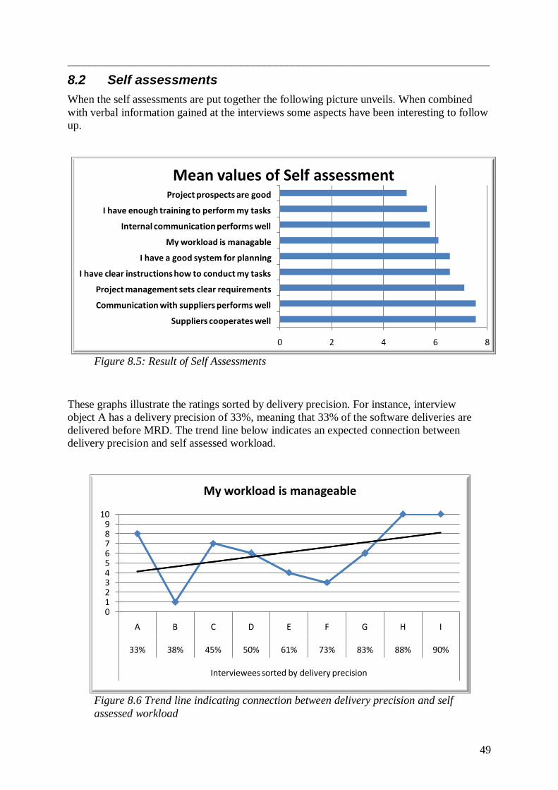
___________________________________________________________________________
49
8.2 Self assessments
When the self assessments are put together the following picture unveils. When combined
with verbal information gained at the interviews some aspects have been interesting to follow
up.
Figure 8.5: Result of Self Assessments
These graphs illustrate the ratings sorted by delivery precision. For instance, interview
object A has a delivery precision of 33%, meaning that 33% of the software deliveries are
delivered before MRD. The trend line below indicates an expected connection between
delivery precision and self assessed workload.
Figure 8.6 Trend line indicating connection between delivery precision and self
assessed workload
0 2 4 6 8
Suppliers cooperates well
Communication with suppliers performs well
Project management sets clear requirements
I have clear instructions how to conduct my tasks
I have a good system for planning
My workload is managable
Internal communication performs well
I have enough training to perform my tasks
Project prospects are good
Mean values of Self assessment
0123456789
10
A B C D E F G H I
33% 38% 45% 50% 61% 73% 83% 88% 90%
Interviewees sorted by delivery precision
My workload is manageable
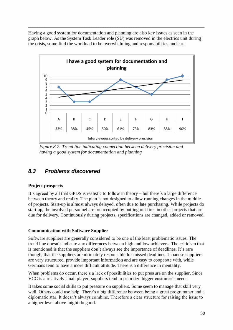
___________________________________________________________________________
50
Having a good system for documentation and planning are also key issues as seen in the
graph below. As the System Task Leader role (SU) was removed in the electrics unit during
the crisis, some find the workload to be overwhelming and responsibilities unclear.
Figure 8.7: Trend line indicating connection between delivery precision and
having a good system for documentation and planning
8.3 Problems discovered
Project prospects
It‟s agreed by all that GPDS is realistic to follow in theory – but there´s a large difference
between theory and reality. The plan is not designed to allow running changes in the middle
of projects. Start-up is almost always delayed, often due to late purchasing. While projects do
start up, the involved personnel are preoccupied by putting out fires in other projects that are
due for delivery. Continuously during projects, specifications are changed, added or removed.
Communication with Software Supplier
Software suppliers are generally considered to be one of the least problematic issues. The
trend line doesn´t indicate any differences between high and low achievers. The criticism that
is mentioned is that the suppliers don‟t always see the importance of deadlines. It‟s rare
though, that the suppliers are ultimately responsible for missed deadlines. Japanese suppliers
are very structured, provide important information and are easy to cooperate with, while
Germans tend to have a more difficult attitude. There is a difference in mentality.
When problems do occur, there‟s a lack of possibilities to put pressure on the supplier. Since
VCC is a relatively small player, suppliers tend to prioritize bigger customer‟s needs.
It takes some social skills to put pressure on suppliers. Some seem to manage that skill very
well. Others could use help. There‟s a big difference between being a great programmer and a
diplomatic star. It doesn‟t always combine. Therefore a clear structure for raising the issue to
a higher level above might do good.
0123456789
10
A B C D E F G H I
33% 38% 45% 50% 61% 73% 83% 88% 90%
Interviewees sorted by delivery precision
I have a good system for documentation and planning
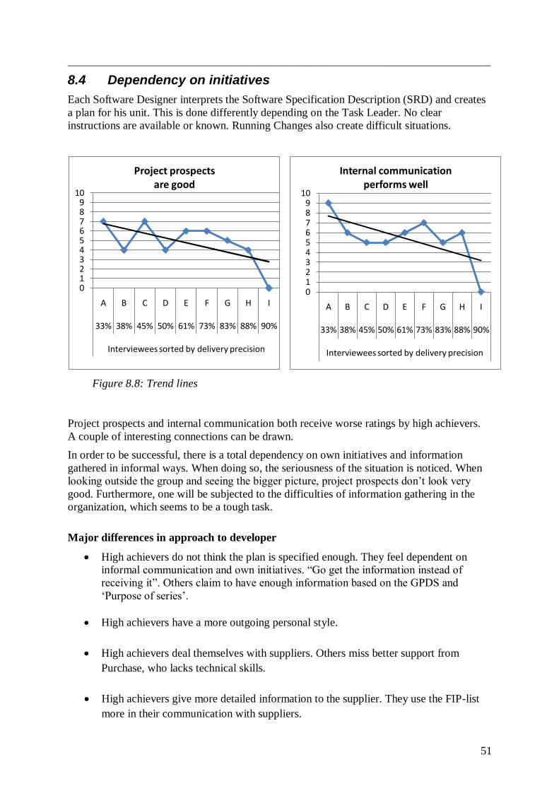
___________________________________________________________________________
51
0123456789
10
A B C D E F G H I
33% 38% 45% 50% 61% 73% 83% 88% 90%
Interviewees sorted by delivery precision
Project prospects are good
0123456789
10
A B C D E F G H I
33% 38% 45% 50% 61% 73% 83% 88% 90%
Interviewees sorted by delivery precision
Internal communication performs well
8.4 Dependency on initiatives
Each Software Designer interprets the Software Specification Description (SRD) and creates
a plan for his unit. This is done differently depending on the Task Leader. No clear
instructions are available or known. Running Changes also create difficult situations.
Project prospects and internal communication both receive worse ratings by high achievers.
A couple of interesting connections can be drawn.
In order to be successful, there is a total dependency on own initiatives and information
gathered in informal ways. When doing so, the seriousness of the situation is noticed. When
looking outside the group and seeing the bigger picture, project prospects don‟t look very
good. Furthermore, one will be subjected to the difficulties of information gathering in the
organization, which seems to be a tough task.
Major differences in approach to developer
High achievers do not think the plan is specified enough. They feel dependent on
informal communication and own initiatives. “Go get the information instead of
receiving it”. Others claim to have enough information based on the GPDS and
„Purpose of series‟.
High achievers have a more outgoing personal style.
High achievers deal themselves with suppliers. Others miss better support from
Purchase, who lacks technical skills.
High achievers give more detailed information to the supplier. They use the FIP-list
more in their communication with suppliers.
Figure 8.8: Trend lines
___________________________________________________________________________
52
All interviewees have a way of their own to organize their work. Software plan,
communication praxis, interpretation of SRD and FIP. To develop a standard to do things and
better coordination between the groups are key issues. Some ways are better than others but
experiences don‟t seem to be communicated. All interviewees have given a unique answer to
every question.
Common problems
Lack of feedback – Nothing to compare against
Demands are not stated clearly. Task leaders are unaware of their performance
compared to others. Since it isn‟t known there is no search for better ways to work.
Demands are not stated clearly in “Purpose of Series”
„Purpose of Series‟ should help scheduling deliveries from software suppliers, but is
not specific enough to make a difference.
Poor information about project changes.
There is no guideline to hold on to. Nor does the Task Leader know the performance of his
own unit or how high performance is expected. No reward is given for a job well done and it
doesn‟t have consequences to perform badly. The DPL is nearest responsible for software
performance. It‟s of course easier to do nothing. It could be a fear of conflicts. It‟s up to the
DPL to keep high standards, but it doesn‟t seem to be subjected to any risk of losing the
position if it isn‟t done.
8.4.1 Solution - Clear and known processes
Needed changes:
A clear structure for raising the issue of negotiation with supplier to a higher level.
IT-system to coordinate diverse aspects and provide current information, making
information search less demanding.
Specifications should be broken down to node level in the Specification Requirements
Description (SRD), to assure generic handling in all units.
The Function Designer should have the overall responsibility throughout the project,
making misunderstandings less likely to occur.
Better feedback and a forum for discussing plans and methods.
Improve the Purpose of Series Document. Add details about all needed software for
each series.

___________________________________________________________________________
53
8.4.2 Incentive system
This is usually associated with economic means. Money is of course a driving force but there
are others too.
The Hawthorne effect is a well known example from the Human relations movement that
shows another aspect of what motivates us. Recognition, to be seen and be shown interest, is
a factor whose importance is often understated. In this case it appears to have a big
unexploited potential.
8.4.3 Support from Product Development Manager necessary
The organization is structured as a matrix. Each project has a hierarchy of its own. In order
to have changes like this implemented in all units, the instruction must ordinate from PD-
level. That‟s where all three units first meet in the hierarchy.
Figure 8.10gbbf
PD
PEM
DPLChassies
DPLElectrics
DPLPowertrain
Figure 8.11: Matrix organization
Figure 8.9: Hierarchy organization

___________________________________________________________________________
54
9 APPLYING THEORY
This chapter compares the situation at VCC against the theory of organizations and group
dynamics. Over fifty individuals of different professions have been interviewed, covering a
great part of the functions in the development process. The lack of structure in the software
process will be discussed together with subjective conclusions. These conclusions are based
on interviews and meetings attended as observers as well as statistics from self assessments
and Software Coordination Center. To a large extent the information gained by interviews are
subjective interpretations.
9.1 Hardware vs. Software handling
The following figures show a major difference in software and hardware handling in the
initial phase of projects. The highlighting in Figure 9.1 shows the area of concern. BOM,
Bill of Material, is a list where all specifications have been broken down to pieces. It has
been used for decades in hardware development, but not within software development. It‟s up
to each Task Leader and Software Designer to do that. How to do it is not specified, therefore
creating an insecure process. The handling of specifications is done differently in each unit.
The formal rules are not sufficient and an informal way of doing things has taken its place.
Bill Of Material
Figure 9.1: Major differences in software and hardware handling

___________________________________________________________________________
55
0
2
4
6
8
10
1 2 3 4 5 6 7 8
Comparison of self assessed competence and delivery precision
Compentence (self assessed)
Delivery precision
1 2 3 4 5 6 7 8
Proportionally put on top of each other
9.2 Isolated groups
The lack of structure makes the process very dependent on communication skills among the
units. An informal way of working can do well up to a certain point when the organization
simply becomes too big.
Depending on the Task Leader, things are done differently. Some ways are more successful
than others, but experiences don‟t seem to be communicated. Each group has their own
structure, their own thinking – and very little knowledge about things outside the group.
9.3 Feedback and handshaking
The group's blind field contains things that members do not see, but others do (Johari
Window). We carry on the same way and often fail to recognize things like unnecessarily
complex procedures. The different groups all have their unique way.
Paradoxically, the most ambitious teams are often full of self-criticism, while groups that
function poorly conceal this by overestimating themselves. Eight software designers assessed
their competence on a scale from 0-10. The answers here are combined with statistics from
Software Coordination Center.
If we ignore all other variables in the graphs above, such as different software suppliers and
complexity of different nodes, we get a clear view. One can interpret the diagrams in two
ways. Either the interviewees on the left side are compensating for a known lack of
competence, or they don´t know what is expected of them.
Figure 9.2: Self assessed competence compared to delivery precision

___________________________________________________________________________
56
A view shared by many is that Software Design Review Meeting (SW-DRM) lacks pressure
on the Software Designers. Failing to deliver is not even embarrassing. If we are never told
otherwise, we will think that everything is in order. Therefore no effort will be taken to find
ways to improve.
Mistakes and misunderstanding are common between the units. The lack of handshaking adds
misunderstandings, one to the other, and builds information that is very far from the original
intention. E.g. the FAD, Function Area Description, is followed by the SRD, System
Requirement Description, and so on, as shown in the figure above. Sometimes mistakes
are not found until the delivered software fails to function.
No handshake SYSTEM DESIGNER
FUNCTION DESIGNER FUNCTION
AREA DESCRIPTION
SYSTEM REQUIEREMENT
DESCRIPTION
Figure 9.3: There is a lack of handshaking between different areas

___________________________________________________________________________
57
9.4 Organizations inside the organization
The development process involves a huge number of units with similar or diverse purposes.
Planning is conducted at different levels and development is divided into groups based on
their corresponding hardware. Moreover there is testing, coordination, implementation - the
list can be made long.
Figure 9.4: Different point of views depending on placement
The members of a unit obviously see the problems they are dealing with themselves clearer
than problems in other units. Groups and organizations with fixed boundaries often have a
way of thinking about themselves and others. What is significant is that you don´t know the
ones outside the group. You don´t know what they do and how they do it. “We are good, the
threat is on the outside”. If problems occur, it‟s because of unfortunate circumstances –
usually caused by those on the outside. "Those outside" have been uninvolved or
irresponsible. In one aspect the thinking pattern fills a purpose within the group. It creates a
good atmosphere and closer bonds between members. Therefore, it‟s not always prioritized to
stay current with the other groups.
This is probably no news. For some it might be, when placing it into the context of software
development at VCC. Awareness of its existence is important. We often carry on in the same
way, not reflecting on issues like this. When listening to interviewees, the blame for problems
is often put on a unit as far away as possible.
To illustrate another example, people involved in product planning sometimes see other
brands releasing a new function. They want the same function implemented in a car under
development. They can´t see how there can be a problem “writing a few extra lines of code”
in the middle of a project. In fact, it causes major problems. People on the other side might –
maybe rightfully – disagree with many changes. Projects are scheduled by GPDS, but when
running changes make it impossible to follow, what´s the use?
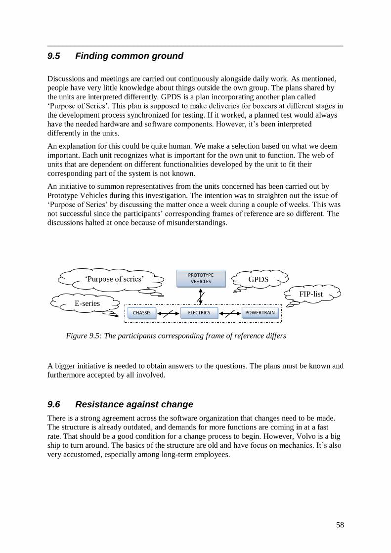
___________________________________________________________________________
58
9.5 Finding common ground
Discussions and meetings are carried out continuously alongside daily work. As mentioned,
people have very little knowledge about things outside the own group. The plans shared by
the units are interpreted differently. GPDS is a plan incorporating another plan called
„Purpose of Series‟. This plan is supposed to make deliveries for boxcars at different stages in
the development process synchronized for testing. If it worked, a planned test would always
have the needed hardware and software components. However, it‟s been interpreted
differently in the units.
An explanation for this could be quite human. We make a selection based on what we deem
important. Each unit recognizes what is important for the own unit to function. The web of
units that are dependent on different functionalities developed by the unit to fit their
corresponding part of the system is not known.
An initiative to summon representatives from the units concerned has been carried out by
Prototype Vehicles during this investigation. The intention was to straighten out the issue of
„Purpose of Series‟ by discussing the matter once a week during a couple of weeks. This was
not successful since the participants‟ corresponding frames of reference are so different. The
discussions halted at once because of misunderstandings.
A bigger initiative is needed to obtain answers to the questions. The plans must be known and
furthermore accepted by all involved.
9.6 Resistance against change
There is a strong agreement across the software organization that changes need to be made.
The structure is already outdated, and demands for more functions are coming in at a fast
rate. That should be a good condition for a change process to begin. However, Volvo is a big
ship to turn around. The basics of the structure are old and have focus on mechanics. It‟s also
very accustomed, especially among long-term employees.
CHASSIS ELECTRICS POWERTRAIN
PROTOTYPE VEHICLES GPDS
FIP-list
E-series
„Purpose of series‟
Figure 9.5: The participants corresponding frame of reference differs

___________________________________________________________________________
59
“That won’t work”
The words seem to come as a reflex when changes are proposed. Changes always cause
problems in the initial phase. That might be why people fear them. It could also be a fear of
losing a formal or informal position by applying it. However, it is the normal way to act. At a
meeting intended to discuss changes a man had an outburst and asked “Don‟t we already
build cars or what!?” This kind of behavior is called regression and is a typical irrational way
of acting in situations that make us disturbed.
On the other hand we are dependent on progress. It‟s the changes that have led us to where
we are today. If the change has a good foundation, the resistance often wears out quickly.
When it has been implemented and employees get used to it, the benefits begin to unveil. You
don‟t build a city overnight, and without changes, Volvo would have only one car model. Its‟
name would be Jacob.
9.7 Lean Product Development System
The basic idea of Lean Product Development System is eliminating waste, adding nothing but
value. The product development in VCC requires running changes into the project process,
making it possible for VCC to deliver the style and features required by the customers.
Running changes are necessary to obtain market share. But this also means that engineers in
the beginning of the project‟s process know that the effort must be made over and over again,
and that is really is a big waste. It is time for VCC to overlook the software process and find
new ways to handle the processes, in order to put the work effort “just in time” and having
engineers do their work only once.
Comparing to how the workload is distributed, engineers must put all their effort to “put out
fires” instead of working according to the GPDS plan. A new project requires about 50
months of development; this is what the hardware development requires to be developed.
Software can be developed much faster than this but must also follow the hardware process,
because they go hand in hand. The most difficult task to perform is to predict how the world
is going to look like and what features the customers will be expecting from a car three to
four years ahead. For example, to develop features into the car that will be compatible with
the iPhone6 or 7 within three years is almost inpossible. Not even Apple knows what those
gadgets will contain.

___________________________________________________________________________
60
2
3
5
10 COMMON PROBLEMS AND SUGGESTED SOLUTIONS
This chapter presents problems which cause late deliveries of the software to the building of
prototypes. Some of the problems will be added with a solution suggestion. Other problems
will just be highlighted for VCC, to show that this is a problem and should be dealt with. The
problems will be sorted into five categories: Structure, Communication, Tool and System,
General problems and Other Problems.
The red numbers refers to the suggested solutions shown in the Appendix B2.
10.1 Structure
Problems caused due to lack of structure.
10.1.1 Building of Boxcar
Problem:
The tests in boxcars are planned to be done in the same week as the building of the boxcars.
This causes problems because the tests can‟t be started before the boxcar is built.
Solution:
The building of boxcar is moved one week earlier in order to be ready for the start of tests.
The boxcar should then be finished at MRD1.
10.1.2 MRD0/MRD1 and acceptance test
Problem:
The software should be delivered to VCC at MRD0 according to the plan. At the same time
SCC should get the software. This causes problems due to that an acceptance test should be
done before the software delivery to SCC.
Solution:
The software is delivered to VCC at MRD0 which then is acceptance tested and delivered
one week after to SCC at MRD1. This is already in the plan and will be changed soon.
10.1.3 SCC, Software Coordination Center
Problem:
SCC has a central role in the software management process handling all the software releases.
When dealing with other units, the SCC-team lacks pressure. The SCC unit is by tradition a
part of the EESE department (see figure 10.1 below) which can be a reason for the lack of
respect, they are at the same level as the other departments. Once, it was easy to see why,
because all software was connected to hardware developed in the same unit. Today the
situation has changed. Software has now become such a large part of the car that there is no
reason for SCC to remain under the EESE department.
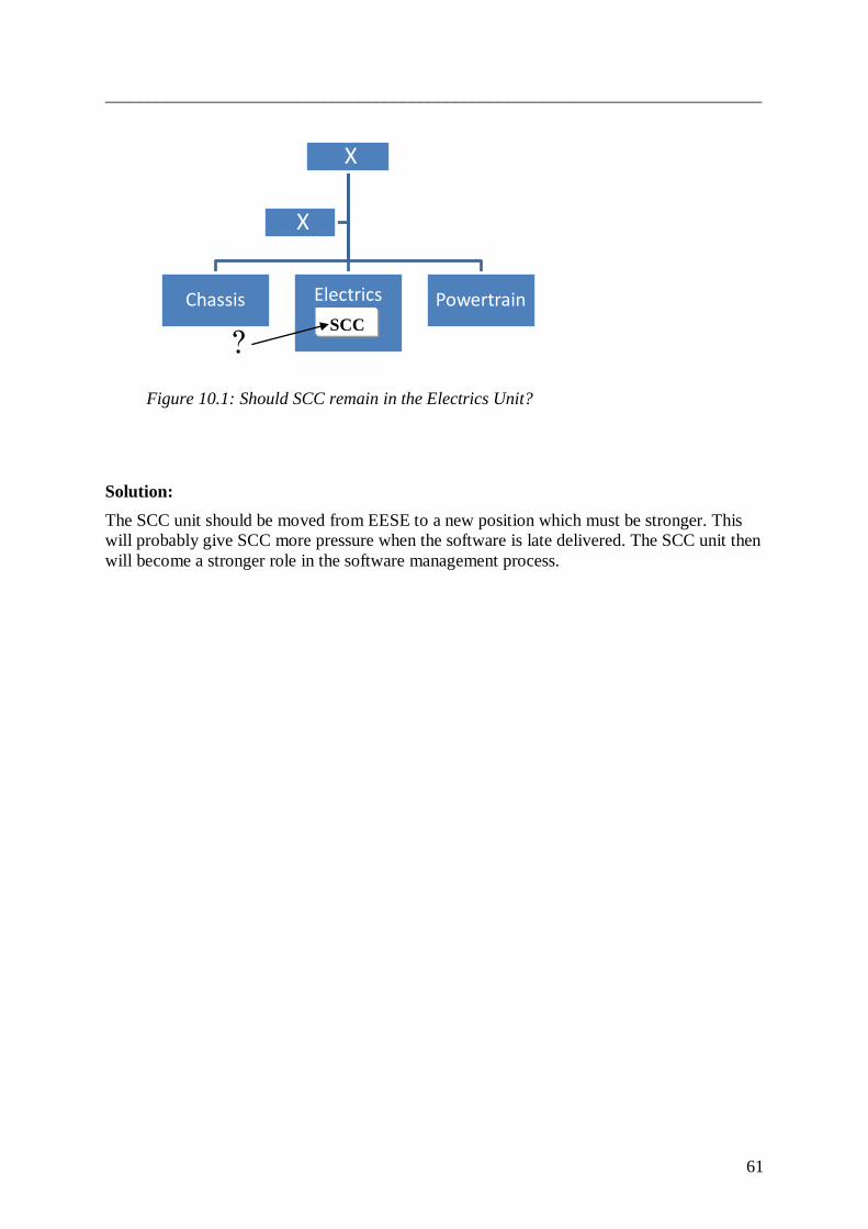
___________________________________________________________________________
61
Figure 10.1: Should SCC remain in the Electrics Unit?
Solution:
The SCC unit should be moved from EESE to a new position which must be stronger. This
will probably give SCC more pressure when the software is late delivered. The SCC unit then
will become a stronger role in the software management process.
X
Chassis Electrics Powertrain
X
? SCC
___________________________________________________________________________
62
10.2 Communication:
Problems caused due to lack of communication.
10.2.1 Feedback
Problem:
In such a large company as VCC it‟s hard for employees to see the whole picture and follow
if specified things have been understood in the correct way. This can lead to a lot of problems
when descriptions can be interpreted in other ways than intended. Descriptions of functions
have to be completely clear to make sure that the next unit understands them. There can‟t be
any misunderstandings between the units. The FAD, SRD and SWRS have to be spotless and
crystal-clear when written, but are often vague and hard to understand. This causes problems
for the following units who have to try to work with the vague description.
Solution:
Sign-offs should be better to make sure the receiving unit understood the description as
intended. They should work according to the V-model (see 10.6).
10.2.2 Feedback to Task Leaders
Problem:
The Task Leaders don't know their on-time-delivery precision e.g. the performance is not
known. This is important feedback. In order to improve you need to know that you have a
problem and what it is.
Solution:
Check at SCC how well the different Task Leaders are doing and send it to the DPL who can
give them feedback and work with the ones who need to improve.
10.2.3 Communication between departments
Problem:
When developing a car all departments have to work synchronized in order to get the
prototype finished in time. They are all working for the same goal and need to communicate
in a good way. This is a problem at VCC. The communication between EESE and Power
train is not sufficient. They are both needed when testing in mules (M1) and VP and should
work together as a team with the same main goal.
10.2.4 Communication between Task Leaders
Problem:
In order for a function to work it usually needs several nodes working together. This demands
a good level of communication between the different nodes. Sometimes at VCC the
communication is deficient and the Task Leaders just focus on the thing they have to deliver
and not on the function which should be implemented. The FIP should help the Task Leaders
to focus on the functions but is sometimes not sufficient enough.
___________________________________________________________________________
63
10.2.5 Communication between Task Leader and SW-supplier
Problem:
How to handle the supplier varies a lot between different Task leaders/Software Designers.
Some of them are very good in communicating with the supplier when others have bigger
problems. When the supplier misses a deadline or disagrees with the Task Leaders/Software
Designers there is not much the Task Leaders/Software Designers can do. Volvo is a small
customer for the supplier and there aren‟t many suppliers VCC can choose from. This leads
to a lack of respect from the supplier and more difficulties for VCC to get their demands
accepted. Another thing that adds to the problem is that VCC has about 40 different suppliers
which all have different ways of working.
Solution:
Set a standard how to handle the supplier.

___________________________________________________________________________
64
1
10.3 Tools and systems:
Problems caused by the lack of system or tools, or problems in a tool or system.
10.3.1 BOM-list
Problem:
The SCC unit doesn‟t have a part list to check what software parts should be delivered to
MRD0 (on suggested flowchart MRD1,Appendix B2) and CRB. Late deliveries which are not
brought up in SW-DRM are noticed first at MRD0 (on suggested flowchart MRD1), which
causes problems for the verification teams (A&V) who have to replan their tests. The NCM is
not sufficient enough to get the software delivered in time. Both SCC and the Task Leaders
should know from the top what should be delivered and not from the person delivering (the
Task Leader).
Solution:
A “SW-BOM” (function list) is created which shall correspond to the HW-BOM that already
exists. The SW-BOM-list includes information about what articles should be delivered to
MRD0 (on suggested flowchart MRD1) for each E-series and M1/VP. This list makes it
possible for SCC to be able to check if the software articles will be delivered on time. This
will also help the verification teams (A&V) who will get quicker information when
something is delayed and can then plan their tests better. Also the Task Leaders obtain better
knowledge and structure of what they are supposed to deliver.
10.3.2 GPDS plan is not followed
Problem:
Ther are many reasons to why the the normal way of doing things is to not follow the plan.
When running changes are forced into the GPDS plan, the plan cannot be followed any more.
According to GPDS the functions-list should be frozen at a certain time, and no more
functions should be added or changed. But even then a running change can be forced and the
function list changed, the freezing of the list is overruled. This leads to problems for all the
units when the plans have to be changed and extra resources have to be used to fix the late
change. When a running change is forced it is okay not to follow the GPDS-plan. This sends
signals that it‟s okay not to follow the plan and problems can be fixed outside the plan.
___________________________________________________________________________
65
10.3.3 Purpose of Series
Problem:
Some of the Task Leaders and the SCC unit don‟t know what should be tested and delivered
at/to each series. Another problem is that people think that E2 should have the same software
as M1, which is not the case. All this should be included in the Purpose of Series Document.
The Function Designer should also be able to look into the Purpose of Series Document to
see when the designed function should be tested/implemented. The Purpose of Series
Document is very vague and lacks information. This planning document would help a lot in
the process when correctly written but at the moment no one takes responsibility for it.
Solution:
Improve the Purpose of Series Document by making it more specified and make sure every
department use it. VCC has to figure out who must be responsible.
10.3.4 The FIP
Problem:
The FIP is not completely accurate, it contains empty slots and is more of a forecast than fact.
The problem is that the FIP sometimes is seen as fact. The FIP isn't working as intended and
doesn‟t give the help needed for the Task Leaders.
Solution:
The FIP should be changed from a forecast to an order. Instead of telling people what might
be implemented at the different series it should work as a plan to follow. The task leaders
should follow the FIP and work with the functions and not just software articles. The FIP
could be of so much help if it were working correctly. The FIP should also be broken down to
node level before being given to the Task Leaders.
10.3.5 The KDP-system
Problem:
KDP is first used at the VP series and is a help. But when it comes to E-series and M1 the
KDP system isn‟t used. The system makes it easier to organize and structure the work.
Problems caused by human errors could be minimized with the help of a system.
___________________________________________________________________________
66
10.4 General problems:
Problems which are general for all the departments and units.
10.4.1 Running changes
Problem:
VCC is a small car company in a global perspective and competes in the premium car league.
The other car companies competing in this league are BMW, Mercedes and Audi. Those
companies are much bigger and have a stronger economic platform compared to VCC.
VCC is forced to do running changes to compete in this league. But there are lots of problems
with running changes.
Solution:
VCC needs to look into this.
10.4.2 Putting out fires
Problem:
Instead of being well prepared and following the plan a ”putting out fires” mentality has
occurred at VCC. When one problem is fixed, the next problem has to be dealt with. The
problems have started long before they are dealt with. VCC is handling the problems in a
wrong way, e.g. in the beginning when problems occur the solution is to order the people
responsible to fix it telling them that it‟s their problem. Ignoring problems like this cause
even more problems when the workload is moved to the end of the project.
Solution:
People should help each other as a group. In the end of a project when a problem occurs
everybody helps to fix it and it should be so in the beginning of the project as well. Problems
should be dealt with before they get too big.
10.4.3 Missing a deadline
Problem:
Missing a deadline has become a normal way of working at VCC. The biggest reason for
missing a deadline is running changes which are the systems‟ fault. This makes delayed
deliveries and missing of deadlines more accepted because it's the running changes of the
systems‟ force. The system loses respect when it‟s okay to miss a deadline over and over
again. It is also easier to miss a deadline in the beginning when its two years until the car
should be ready. People can‟t see how much it affects the units in the end when they are a
little late.
Solution:
Missing a deadline in the beginning of a project shouldn't be more accepted than in the late
part of the project. People should help each other at the beginning in the same way as they do
at the end. DPL and SCC should make it clear that missing a deadline is not acceptable.

___________________________________________________________________________
67
10.4.4 Software importance
Problem:
The Software is not delivered in time and it‟s time to realize that software is becoming a
bigger and bigger part of the car. It‟s not just a couple of lines written in a program, it‟s a
vital part of the car. The software is not treated with the same respect as the hardware. The
software will probably continue to increase in cars in the future, so it‟s time to change and be
best at it.
The hardware process has a clear structure which is not the case for the software process.
Hardware is easier to get a grip on. It‟s known that it takes time to adjust tools for
manufacturing and that those can‟t be changed overnight. What is neglected or not known is
that the same goes for software. Changes can´t be implemented overnight. Software
Designers rate suppliers high according to their self assessment, see Appendix A2. The
problem is in VCC.
Solution:
Software should be treated with the same importance as hardware and have a clear structure.
TRM should treat software with the same importance as hardware. This also goes for the
DPL.

___________________________________________________________________________
68
4
10.5 Other problems:
Problems that do not fit into any other category:
10.5.1 Implementing of the Function
Problem:
There are hundreds of functions in a car and it‟s the functions/features the customer values.
So it is very important that the functions are working. When a function doesn‟t work there is
no one to hold responsible. The Functions Designers who ordered and wrote the description
for the function are already working on a new project.
Solution:
The Function Designers should be responsible that their function is working as intended at
the end. They should also get feedback during the process and check what is happening. They
should make sure that the nodes who are working with the function are communicating. The
function designer should write the test order at the end and see if the function is working as
intended. The V-model (see 10.6) shows how it should be done.
10.5.2 E2 and M1
Problem:
Employees don‟t know that software for E2 and M1 shouldn't be the same. At the moment
there is a lot of confusion and beliefs that E2 and M1 should get the same software because
they are being built at the same time. The hardware can vary a lot between the two, therefore
different software must be delivered.
Solution:
This should be added in the Purpose of Series Document, the SW-BOM and the FIP.
10.5.3 Contracts (Task Leader - Supplier)
Problem:
The Task Leader should have a supplier ready in time to deliver software to the different
series, but in some cases this is not finished until the middle of the E-series. Another problem
is that all the demands are not set when signing a contract with a supplier. So even after
signing a contract with the supplier they have to agree on the demands. Both of these
problems can delay the deliveries of the software.
Solution:
Better feedback and help to Task Leaders who are delayed with the software deliveries.
___________________________________________________________________________
69
10.5.4 DPL
Problem:
There is not enough structure for the DPL to follow the employees, e.g. when the C-notes
should be set. The DPL doesn‟t have enough detailed understanding of what‟s happening and
cannot help the employees until the problem already is upon them.
Solution:
Bring back the SU role and/or get a better system or structure for them to see how it is going.
10.5.5 Acceptance test
Problem:
There is lack of structure of what should be tested and it often depends on the experience of
the tester.
10.5.6 SW-DRM
Problem:
There is lack of respect for this meeting, sometimes the DPL doesn‟t even show up. The
meeting has a potential that is not fully utilized by the Software Designers or the Task
Leaders, which have little control over their own deliveries to the respective series, according
to the SCC team.
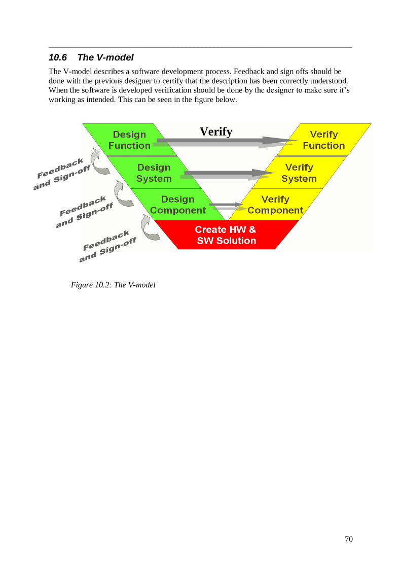
___________________________________________________________________________
70
10.6 The V-model
The V-model describes a software development process. Feedback and sign offs should be
done with the previous designer to certify that the description has been correctly understood.
When the software is developed verification should be done by the designer to make sure it‟s
working as intended. This can be seen in the figure below.
Verify
Figure 10.2: The V-model

___________________________________________________________________________
71
10.7 Recommendation
As seen in this chapter many improvements are possible at VCC. Solving the problems all at
once would be very difficult. In this part a recommendation to VCC will be made as to where
to start the improvement work. The four things VCC are recommended to start with are:
Task leaders and the SCC need better structure with the help of a SW-BOM
The problem today is that there is no structured way of knowing what the Task Leaders
should deliver to SCC. With the help of the SW-BOM both the SCC-team and the Task
Leaders could more easily see what is supposed to be delivered. The SW-BOM will be
created from the KDP-system as the HW-BOM. This will help because the problem with
human errors will decrease when a system is involved. This should also be fairly easy to
implement when a BOM-list already is created for the hardware.
The SCC-team needs stronger status
SCC is the team collecting and releasing all the software parts from the different departments.
When a Task Leader is delayed with the delivery there is not much that the SCC team can do.
They have to trust in the DPL from that department to fix the problem. The DPL is the one
who agrees and acts on late deliveries in their own department. This is a bit weird because the
DPL will then check if his own work is good enough. One reason for the lack of respect for
SCC could be that they are a part of the ESSE department, other departments at the same
level may think it‟s not a major thing to be late with deliveries to another department at the
same level. So the SCC team should have a stronger position instead of working under the
EESE department. SCC should be moved in order to make them more powerful.
The Function Designers need to be responsible for the implementation of their function
The functions are highly important in the car. VCC needs someone in charge of each function
who can see the whole picture. The function Designer is the best one to do this work. This
will probably help to get a higher working percent on the first functions test.
Departments and units need to interpret common plans and tools in the same way
This is a big problem in VCC. What‟s the point of having a plan when departments read it in
different ways? There must be a clear and common way of understanding plans and tools.
Communication between the different departments need to work perfectly when they are so
dependent of each other. VCC must look into this directly and continue to work with this.
Software is now a part of the car and needs to be dealt with in the same way as the hardware,
they are equally important. This is a major problem needed to be fixed in order to make VCC
a better working company.

___________________________________________________________________________
72
11 CONCLUSION
This chapter will summarize and conclude the report. The objectives, experiences and an
analysis of the work that has been done will be discussed. Three initial issues were mentioned
in the introduction.
How does the current process work today?
The process was mapped up on a high level to make room for all major units on a single
page. It provides a compressed view of the complete process, only involving the relevant
units and roles. This has not been available before. The map is included in Appendix B1.
How can the current process be improved?
Suggestions for improvement have been given in a number of areas. The most important ones
are listed below. It is also visualized in an improved software map, included in Appendix B2.
Can the software process be as organized as the hardware process?
In some aspects it can, in others not. Software BOM seems feasible to implement, giving a
better structure for software releases. A key ingredient is also to realize the limitations of
software development in the same manner as the restrictions of hardware development are
known. Pushing for impossible demands will result in quality problems and poor delivery
precision.
11.1 Experiences
The initial delimitations were soon discarded as too narrow. To understand the problems the
investigation had to be made further back in the process. That made the scope so wide that
the time schedule was too limited. Understanding the process in ten weeks is hard enough.
This has unfortunately forced us to leave interesting issues out. Creating solutions for all
problems proved to be inconceivable. The focus was moved to just pinpoint the problems. A
number of problems have been verified, giving some insight in the complex structure.
It has been surprisingly easy to book meetings. People have been very cooperative and have
managed to add meetings to their already busy schedule. A lot of people were interested in
using the thesis as a means of communication to make themselves heard and share their
views. That might indicate a weakness in the communication structure. People see problems
and have ideas but need the attention of the management to carry out improvements. This
seems difficult.
___________________________________________________________________________
73
11.2 Credibility analysis
These conclusions are based on interviews and meetings attended as observers as well as
statistics from self assessments and Software Coordination Center. To a large extent the
information gained by interviews are subjective interpretations and analysis.
There is no doubt that the problems mentioned exist. What can be discussed is the seriousness
of some of them and whether they are problems in themselves or symptoms of bigger ones.
11.3 Recommendations
With that in mind, the most important ways of improvement have been found to be the
following:
The Function Designers need to be responsible for the implementation of their
function during the whole project.
Task leaders need better structure, feedback and less isolated groups.
To set goals and measure performance. To provide knowledge about what is expected.
Software Coordination Center needs higher status and a better IT-solution for
coordination.
Task leaders, Software Coordination Center and Software Testers need better
structure by implementing a SW-BOM.
Units need to interpret common plans and tools in the same way. Resources are
needed to start a project involving all concerned in order to create understanding of
others needs and a common interpretation.
The Purpose of Series Document needs to be improved by adding more specific
demands.
11.4 Final words
It‟s obvious that Volvo´s roots are in mechanics. Software doesn‟t seem to be considered an
issue by the management. It‟s not as easy to get a grip on as hardware is. The problems run
deep, and we have probably just touched the tip of an iceberg. On the other hand we have met
many committed and experienced employees. They have all showed a deep interest in finding
ways for improvement. Volvo has a lot of work to do in order to make the process run
smoothly but also a very committed staff.
___________________________________________________________________________
74
Stefan Jacoby, President and CEO of Volvo Cars, focused on Volvo's
brand refinement and future in the U.S. when he kicked off the Los
Angeles Auto Show by delivering the Motor Press Guild (MPG)
keynote address on November 17th
2010.
"From now on, you can expect us to do things faster, better and smarter,"
says Stefan Jacoby. "We will bring new ideas to the market quicker than
before. We are focusing on a driver centric approach and we will stand out
from the crowd by delivering a distinct, individualist car experience. Not
by copying our main competitors. Instead, we will do it by carving out our
own, unique Scandinavian profile."

___________________________________________________________________________
75
REFERENCES
Reference books:
Granér, Rolf 1994: Personalgruppens psykologi. Studentlitteratur, Lund.
Morgan & Liker 2006: The Toyota Product Development System, Integrating People,
Process, and Technology, Productivity Press, New York
Reference article:
Poppendieck, Mary: Principles of Lean Thinking, LCC 7666 Cernelian Lane, Eden
Prairie, MN 55346 USA, 952-934-7998
Other references:
Brassard, Michael 2002: The Six Sigma Memory Jogger II, A Pocket Guide of Tools
for Six Sigma Improvement Teams, GOAL/QPC, Salem, NH, USA
Reference persons:
Olof Hansson, VCC, Göteborg, tel. 031-325 07 97

___________________________________________________________________________
1
APPENDIX A1
Frågor till KU/SW-ansvariga: Namn: NOD:
Planering:
Känner du att du har rätt förutsättningar att dra igång dina planerade aktiviteter vid
projektstart?
Har du full koll på vilka förserier som skall byggas i ett specifikt projekt och på ditt
innehåll i respektive serie/projekt?
Hur håller du i ordning på komplexiteten av SW-carry over/carry back mellan olika
bilprojekt?
Vet du vad som skall ingå i en SW-leverans (SW, provning utförd, dokument osv)?
ÄO:
Vem har ansvaret för att sköta produktdokumentationen (ÄO:t) inom er nod?
Vad ser du är fallgroparna för att hålla ordning på att produktstrukturen (grind PTCC) är
korrekt beskriven i ditt ÄO? (var gör man mest fel)
Har du rätt kompetens/utbildning för att skriva ÄO:n?
När tidsmässigt sker din etablering/uppdatering av ÄO:t?
Leverantörskontakt:
Hur förmedlar du informationen till leverantören om att den skall leverera
rätt(innehåll / korrekt ) SW i rätt tid?
Har leverantörerna tillgång till SW-plan och våra MRD-tider?
Vilken information är med i ESOW (Syfte serie, FIP)?
Hur hanteras artikelnumren gentemot leverantör?
Hur fungerar samarbetet med inköp rörande SW-frågor?
Erfarenhet kring nya/gamla leverantörer?
Huvudfrågor:
Hur säkerställer ni inom ert team att rätt SW levereras i rätt tid till rätt byggnation?
Finns det något du skulle vilja ändra på kring detta?
Din erfarenhet i rollen (antal år, bättre/sämre med åren)?
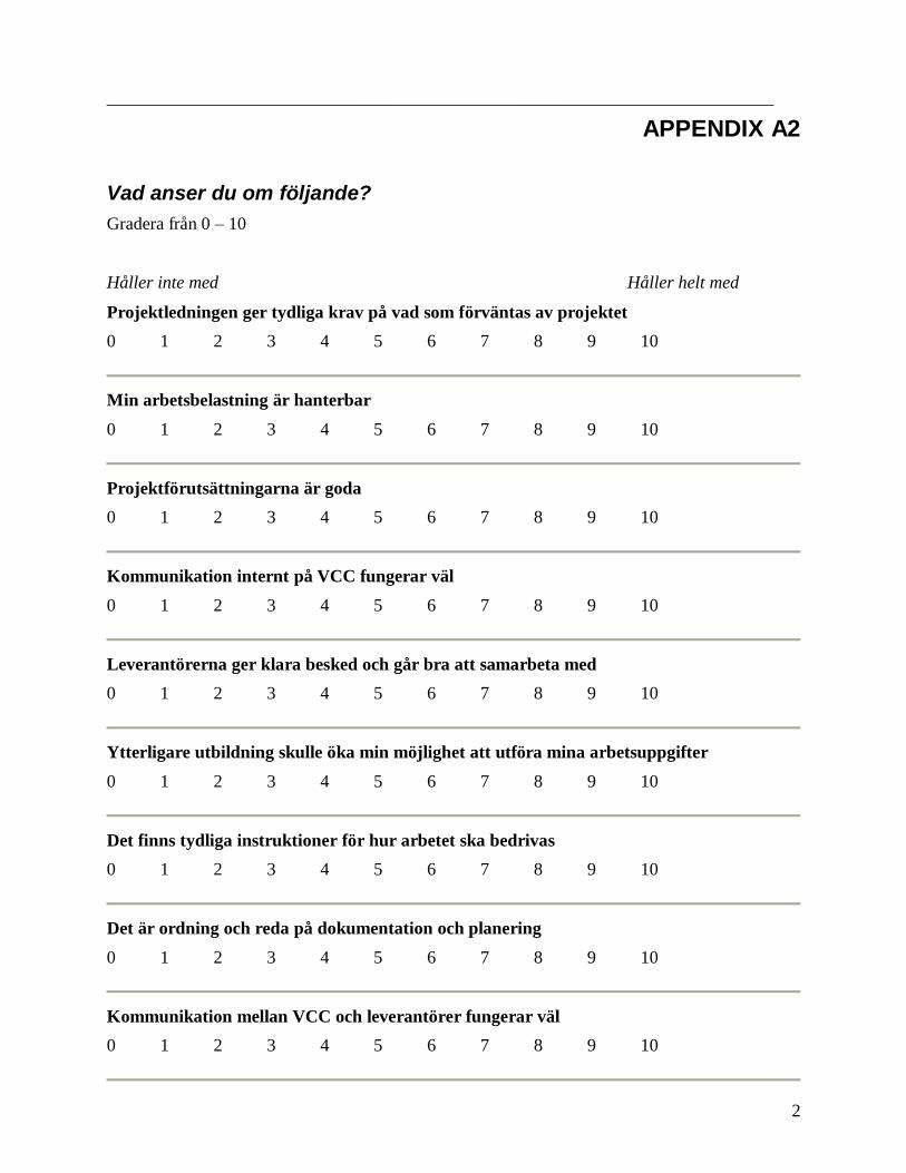
___________________________________________________________________________
2
APPENDIX A2
Vad anser du om följande?
Gradera från 0 – 10
Håller inte med Håller helt med
Projektledningen ger tydliga krav på vad som förväntas av projektet
0 1 2 3 4 5 6 7 8 9 10
Min arbetsbelastning är hanterbar
0 1 2 3 4 5 6 7 8 9 10
Projektförutsättningarna är goda
0 1 2 3 4 5 6 7 8 9 10
Kommunikation internt på VCC fungerar väl
0 1 2 3 4 5 6 7 8 9 10
Leverantörerna ger klara besked och går bra att samarbeta med
0 1 2 3 4 5 6 7 8 9 10
Ytterligare utbildning skulle öka min möjlighet att utföra mina arbetsuppgifter
0 1 2 3 4 5 6 7 8 9 10
Det finns tydliga instruktioner för hur arbetet ska bedrivas
0 1 2 3 4 5 6 7 8 9 10
Det är ordning och reda på dokumentation och planering
0 1 2 3 4 5 6 7 8 9 10
Kommunikation mellan VCC och leverantörer fungerar väl
0 1 2 3 4 5 6 7 8 9 10
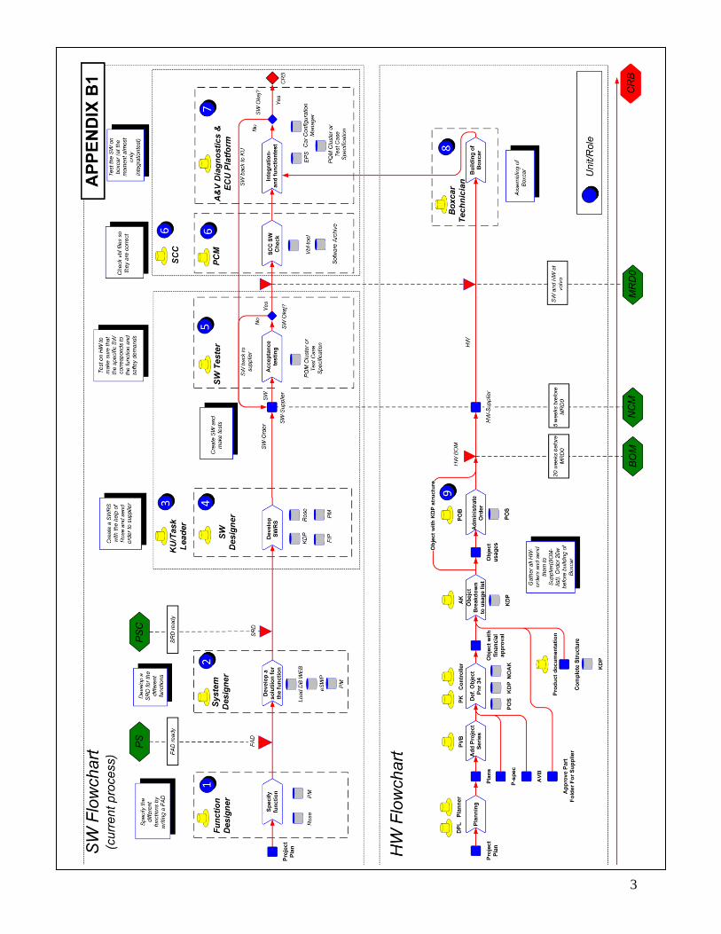
___________________________________________________________________________
3
CURRENT FLOWCHART, APPENDIX B1
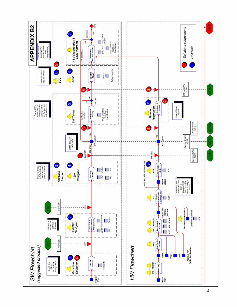
___________________________________________________________________________
4
SUGGESTED FLOWCHART, APPENDIX B2