soil-structure interaction in tunnel construction in soft
TRANSCRIPT
RIVISTA ITALIANA DI GEOTECNICA 2/2017 DOI:10.19199/2017.2.0557-1405.005
Soil-structure interaction in tunnel construction in soft ground
Emilio Bilotta*
SummaryTunnel design and construction involve several specialties and may provide subjects for innovative and multi-disciplinary re-
search. A strong integration between structural and geotechnical engineering, among other disciplines, can be likely envisaged in this field. To this aim interdisciplinary research should mainly focus on the solution of soil-structure interaction boundary value problems.
An overview on the current trends of research in this field is provided in the paper over different scales, starting from the be-haviour of the single element of soil, dealing with the interaction between the ground and the tunnel, and finally approaching the interaction between the underground infrastructures and the built environment.Keywords: soil-structure interaction, underground construction, tunnels, urban areas, seismic behaviour
1. Introduction
Project teams for tunnelling are multi-discipli-nary since they often include structural, geotechni-cal and mechanical engineers, construction special-ists, urban and transportation planners, archaeolo-gists, geologists and other professionals such as law-yers and advisors. For such a reason tunnel projects may open to new and interdisciplinary research op-portunities.
Among the different disciplines involved in tun-nel construction, structural engineering and geo-technical engineering are closer than others and allied. Nevertheless, despite the similar jargon they adopt, differences in approach between them still persist [BURLAND, 2006]. Hence an interdisciplinary integration between them should be pursued, to bring interdependent parts of both disciplines into a close relationship. The solution of soil-structure in-teraction boundary problems is where such an inter-disciplinary effort is largely needed.
This paper is aimed at giving an overview of cur-rent trends of research in the field of soil-structure interaction in tunnel construction in soft ground. They span over different scales, from the behaviour of the single element of soil to boundary value prob-lems of interaction between the tunnel and the sur-rounding ground, and towards larger interaction be-tween the underground infrastructures and the built environment in urban areas.
Within this multi-scale framework, focus will be given to the role of soil-structure interaction in seg-
mental tunnel lining behaviour, in tunnelling-in-duced damage to buildings and in seismic interac-tion between tunnels and buildings.
2. Segmental tunnel lining behaviour
2.1. Structural demand during construction
As far as mechanized tunnelling has increased worldwide in recent years, many efforts were devot-ed by researchers to understand the role of con-struction processes in the forces arising in structur-al lining during mechanized excavation [BLOM, 2002; MOELLER, 2006; DO et al., 2014a,b,c]. Linings made of prefabricated reinforced concrete segments are routinely used in circular tunnels bored by means of earth pressure balance or slurry machines, because they are easily assembled. The segments are jointed to form a ring and sometimes they are bolted togeth-er. Each ring may also be bolted to the previous one along the longitudinal direction. The jointed pattern of a segmental lining has a double effect on the struc-tural lining behaviour: 1) it makes the lining a mul-ti-constrained assembly of segments where the joints behave as semi-rigid connections, with rotational ca-pacity [DO et al., 2014d,e], able to transmit axial forc-es, shearing forces and bending moments; 2) the staggered layout of the joints increases the degree of inter-connection between the adjacent rings thus leading the lining to behave as a 3D structure rath-er than an isolated ring [ARNAU and MOLINS, 2012]. Many experimental studies have shown the effects of joints technologies on their behaviour. CAVALARO and AGUADO [2011] for example, studied the behaviour of a joint packer under simple (normal) and coupled
* Department of Civil, Architectural and Environmental Engineering, University of Napoli Federico II, Italy

RIVISTA ITALIANA DI GEOTECNICA
6 BILOTTA
(normal and tangential) stresses up to failure. They show how the joint behaviour changes according to the packer material (low friction for bituminous packer, intermediate for rubber packer, high fric-tion for concrete-concrete interface). LI et al. [2015] studied the flat bolted longitudinal joint behaviour of Shanghai Metro Line No.13 with a full-scale tests carried out by loading the joint until it is completely damaged. The authors monitored the joint openings both under sagging and hogging, reading different values of moment for the same rotation: the joint un-der hogging moment reaches the same value of rota-tion as under a higher sagging moment.
Recent researches involving both structur-al monitoring and geotechnical calculations have shown that a large part of the internal forces arises in the lining from the very early stages of installation of the individual segments forming the complete ring [BILOTTA et al., 2005; PEPE 2008; BILOTTA and RUS-SO, 2013; FABOZZI et al., 2016; 2017b]. Hence a com-plex three-dimensional interaction takes place, both along the longitudinal direction and in the trans-verse section, between the soil, the structural tube and the grout injected to fill the gap in between. This issue is rather neglected in the current design
practice, since the calculation of the internal forc-es is usually performed assuming that the fully as-sembled ring is exposed to the interaction with the ground.
On the contrary, during tunnel construction, the segmental lining is subjected to a loading pro-cess which pre-stresses the lining before it reaches a steady loading condition under the active loads due to the surroundings [BLOM, 2002]. Longitudi-nal forces compress the lining when the TBM ad-vances: this effect is time-dependent and decreas-es with the distance from the tunnel face . Grout is pumped to fill the gap between the lining and the excavation cut, with enough pressure to min-imize inward displacements, hence the settlement at the ground surface: such a pressure loads radial-ly the lining. Grout flowing around the cavity gen-erates also shear stresses on the lining, changing with time until the grout reaches complete harden-ing, being minimal and negligible the shear stress-es measured when the grout is fresh [BEZUIJEN et al., 2004].
Predicting a realistic lining behaviour, includ-ing all the aspects that have been mentioned so far, may be rather difficult. An accurate structural and
Fig. 1 – Stress paths around mechanised tunnelling (modified after FABOZZI, 2017).Fig. 1 – Percorsi tensionali intorno a uno scavo meccanizzato (modificato da FABOZZI, 2017).
7
APRILE - GIUGNO 2017
SOIL-STRUCTURE INTERACTION IN TUNNEL CONSTRUCTION IN SOFT GROUND
geotechnical model is hence required for a realis-tic evaluation of the lining stresses and strains pro-duced by soil-grout-structure interaction; hence in-ternal forces acting in the lining can be calculated. In the last years many authors have proposed dif-ferent 3D numerical mechanized tunnelling (TBM) models, taking into account in different ways the large number of factors involved in the tunnelling process and modelling the joints with different ap-proaches (e.g. BLOM et al., 1999; KLAPPERS et al., 2006; TEACHAVORASINSKUN et al., 2010; DO et al., 2014e; FORTSAKIS et al., 2013; FABOZZI, 2017).
A three-dimensional numerical approach is prob-ably the best way to reproduce the complexity of the problem without introducing too many assumptions, as in the case of empirical solutions, analytical solu-tions or even simplified 2D numerical analyses [KOIA-MA, 2003]. In addition, a good assessment of the loads acting on the lining during each phase of the exca-vation process is required. Figure 1 shows the stress paths calculated in a three-dimensional numerical analysis simulating several stages of mechanised tun-nelling [FABOZZI, 2017]. It is shown as an example of
stress modification in the ground before the ring of lining is subjected to soil-grout-structure interaction.
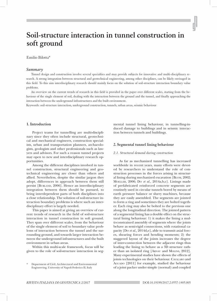
By modelling the three-dimensional staged construction of a stretch of Metro Line 6 in Na-ples FABOZZI et al. [2017b] matched the measured strains of an instrumented ring of lining, moni-tored during construction, in order to back-figure the internal forces acting in the ring. The results showed how the segmental layout of the lining in-volves a not negligible variation of the structural forces along the cross section (Fig. 2), highlight-ing the need to consider both the time-dependent grout behaviour and the jacking thrusts in calcu-lation.
2.2. Seismic behaviour of tunnel lining
A complex interaction mechanism also arises be-tween the tunnel structure and the surrounding soil during earthquakes. Several works based on centri-fuge testing on reduced scale models of tunnels in sand (e.g. CILINGIR and MADABHUSHI 2011; LANZANO et
Fig. 2 – Back-figured internal forces in a segmented ring of lining of Metro Line 6 in Naples (modified after FABOZZI et al., 2017).Fig. 2 – Sollecitazioni in un anello del rivestimento segmentato di Linea 6 (Napoli), calcolate da back-analysis (modificato da FABOZZI et al., 2017).

RIVISTA ITALIANA DI GEOTECNICA
8 BILOTTA
al., 2012; TSINIDIS et al., 2015; 2016a,b,c) have provid-ed experimental evidence of the effects of two main factors influencing the seismic behaviour of tunnels: the soil-lining relative flexibility and the behaviour of the tunnel/ground interface.
The common approach to seismic tunnel design neglects the asynchronous effects in the longitudinal direction and considers the cross section of the tun-nel under plane strain.
When a shear wave propagates perpendicularly to the tunnel axis, the transverse section of a circu-lar tunnel undergoes ovalisation [OWEN and SCHOLL, 1981]. If the dynamic interaction between the ground and the lining is neglected, the maxi-mum shear strain, γmax, due to the shear waves can be calculated in free-field conditions (Fig. 3). The maximum diameter change ∆
dd of an ideal circle in
the continuous elastic medium is [HASHASH et al., 2001]
2maxγ
±=∆dd
(1)
If a circular unlined perforation is considered, the diameter change is dependent on the Poisson’s ratio of the ground, νg:
)1(2 max gdd νγ −±=
∆ (2)
The perforated medium undergoes higher shear deformation (Eq. 2) compared to the intact medium (Eq. 1). If also the lining is considered, the maximum shear deformation is dependent on the soil-structure relative stiffness, and this should be taken into account when computing the stresses in the lining.
Some Authors have suggested formulae for the calculation of the increments of the internal forces
in the lining due to the ground shear strain γ around the tunnel, considering the relative stiffness between the soil and the structure.
Earlier solutions for external loading on under-ground structural cylinders [BURNS and RICHARDS, 1964; HOEG, 1968; PECK et al., 1972] were adapted by WANG [1993] to solve the case of seismic loading on a circular tunnel lining.
Compressive and flexural relative stiffness pa-rameters, C and F, were defined as:
2(1 )
(1 )(1 2 )g s
s s g g
E RC
E tν
ν ν−
=+ −
(3)
2 3(1 )
6 (1 )g s
s g
E RF
E Iνν
−=
+ (4)
where R is the tunnel radius and t the lining thick-ness, E and ν the elastic parameters (subscript s is for ‘structure’ and g is for “ground”).
In full-slip conditions at the tunnel/ground in-terface, WANG [1993] proposed the following equa-tion to calculate the diameter change:
1Δ 1
3 maxd K F
dγ= ± (5)
where K1 is a coefficient that depends on the flexural relative stiffness parameter F and the Poisson’s ratio of the ground:
( )
112 1
2 5 6g
g
KF
υυ
−=
+ − (6)
The maximum changes of hoop force and bend-ing moment in the tunnel transverse section are [WANG, 1993]:
( )116 1
gmax max
g
EN K r γ
υ= ±
+ (7)
Fig. 3 – Calculation of seismic internal forces in the transverse section of a circular tunnel.Fig. 3 – Calcolo delle sollecitazioni indotte da sisma nella sezione trasversale di una galleria circolare.

9
APRILE - GIUGNO 2017
SOIL-STRUCTURE INTERACTION IN TUNNEL CONSTRUCTION IN SOFT GROUND
( )2
116 1
gmax max
g
EM K r γ
υ= ±
+ (8)
In no-slip condition at the tunnel/ground inter-face, WANG [1993] proposed the following equation for the maximum hoop force:
( )2 2 1g
max maxg
EN K rγ
υ= ±
+ (9)
where:
( ) ( ) ( )
( ) ( )
2
22
11 2 1 2 1 221
53 2 1 2 8 6 6 82
g g g
g g g g g
F CK
F C C
υ υ υ
υ υ υ υ υ
− − − − − + = +
− + − + − + + −
(10)
The maximum bending moment is assumed equal to that in full-slip conditions (Eq. 8).
Independently, PENZIEN and WU [1998] and PEN-ZIEN [2000] developed similar solutions for both no-slip and full slip conditions.
The solutions proposed by PENZIEN [2000] for full slip conditions coincide with those by WANG [1993]. Those for no-slip conditions are different. By defining:
'
21
3 4g
g
KF
νν
−=
+ − (11)
PENZIEN [2000] solutions for no-slip conditions can be written as:
( )'2
2 1
gmax max
g
EN K r γ
υ= ±
+ (12)
( )' 22 1
gmax max
g
EM K r γ
υ= ±
+ (13)
By means of FE analyses used as a benchmark, HASHASH et al. [2005] showed that, for common val-
ues of relative stiffness, the increment of bending moment computed by PENZIEN [2000] and WANG [1993] are practically the same; on the other hand, the increments of hoop forces calculated by PENZIEN [2000] are largely lower than both WANG [1993] and their benchmark numerical solution.
Similar analytical solutions have been proposed by PARK et al. [2009] and BOBET [2010]. KONTOE et al. [2014] have recently validated all the four above-mentioned analytical solutions, suggesting that they can be used for preliminary design using equivalent linear properties and the corresponding compatible strain as an approximate way of accounting for non-linear soil response. The maximum shear strain, γmax, due to the SHEAR waves is calculated in free-field con-ditions, from the seismic demand (e.g. PGA or PGV).
Although an equivalent linear approach is gen-erally adopted in practice, the two main factors in-fluencing the seismic behaviour of tunnels, i.e. the soil-lining relative flexibility and behaviour of the tunnel/ground interface, may change during shak-ing due to the non-linear and irreversible behaviour of the soil and of the lining system [PITILAKIS and TSI-NIDIS, 2014; 2017; TSINIDIS, 2017].
Centrifuge experiments on a model tunnel in dry sand undergoing pseudo-harmonic time histo-ries of acceleration of different amplitude and fre-quency [LANZANO, 2009; LANZANO et al., 2012] evi-denced that, further to transient changes of inter-nal forces during wave passage, also permanent in-crements arise in the tunnel lining after strong seis-mic events. Figure 4 compares normalised time his-tories of bending moment in a monitored section of the model tunnel with the time history of surface set-tlement, both in the experiments and in numerical
Fig. 4 – Normalised time histories of bending moment and ground surface settlement in centrifuge tests and numerical back-analyses (modified after LANZANO and BILOTTA, 2014).Fig. 4 – Storie temporali normalizzate di momento flettente e cedimento in superficie misurate in prove in centrifuga e calcolate da back-analysis numerica (modificate da LANZANO e BILOTTA, 2014).

RIVISTA ITALIANA DI GEOTECNICA
10 BILOTTA
back-analyses. The latter clearly indicates densifica-tion of the layer of sand, and this seems well corre-lated with the accumulation of bending moments in the lining section [LANZANO and BILOTTA, 2014].
Figure 5 shows the comparison among the ex-perimental time history of bending moment in the tunnel lining in one of the abovementioned centri-fuge tests on a model tunnel in sand and a series of corresponding numerical results that were obtained by several research groups in the RRTT – Round Rob-in on Tunnel Test [BILOTTA and SILVESTRI, 2012]. This was a contest on the numerical prediction of the be-haviour of the model tunnel, jointly promoted in 2011 by three ISSMGE Technical Committees, i.e. TC104 (Physical modelling in Geotechnics), TC203 (Earthquake Geotechnical Engineering) and TC204 (Underground construction in soft ground).
Both experimental and numerical evidenc-es of permanent changes of internal loads in the tunnel lining [AMOROSI et al., 2014; CONTI et al., 2014; GOMES, 2014; HLEIBIEH et al., 2014; TSINIDIS et al., 2014; ABATE et al., 2015] have indicated that a full dynamic analysis including soil-structure in-teraction and plastic soil behaviour should be per-formed in order to achieve the most reliable seis-mic design of tunnel linings. BILOTTA et al. [2014] observed that the irreversible load increments that arise on the tunnel lining after shaking are a con-sequence of cumulated plastic strain in the sandy layer. Hence the ability of the numerical model to capture such a permanent accumulation of internal forces depends on the attitude of the adopted con-stitutive model to predict plastic volumetric strain associated to shaking.
FABOZZI and BILOTTA [2016] carried out a nu-merical study aimed at modelling the three-dimen-sional performance of segmental linings of a shal-low tunnel under seismic loading. The effect of the construction stages on the seismic behaviour of the tunnel lining is clearly evidenced in the results of this study, indicating that the pre-seismic ground conditions influence the magnitude of changes of
internal force during and after shaking. Numerical results also show the significant effect of the jointed pattern of a segmental lining, which implies a lower structural demand than a continuous ring, due to its larger flexibility and compressibility in the trans-verse section. On the other hand, permanent rota-tions of the joints at the end of the earthquake (Fig. 6) may represent a further structural fragility of a segmental lining, since they may produce disloca-tion of sealing gaskets among segments.
Based on the results of 2D FE analyses using a strain hardening elastic-plastic model for the soil and several input signals, and following a proce-dure proposed by ARGYROUDIS and PITILAKIS [2012], FABOZZI et al. [2017a] have calculated fragility curves for damage associated to joint permanent rotation in a segmental tunnel lining. From a practical point of view, the fragility curves represent the estima-tion of the tunnel vulnerability in the risk analysis field. They may be combined with information on the seismic hazard of the site and on the exposure to estimate losses that can be associated to such a damage. The results of their work show that in seg-mental linings serviceability limit state verifications of the joints are needed, against excessive rotation that may produce dislocation of sealing gaskets among segments.
It is worth noticing that the spatial variation of ground motion affects the longitudinal seismic re-sponse of tunnels [YAN et al., 2015, 2016; YU et al., 2017; YUAN et al., 2017]. This issue cannot be neglect-ed in safety assessment of tunnel linings. In spite of this, a less systematic work seems to have been car-ried out on the analysis of the longitudinal seismic response of tunnels under an asynchronous earth-quake input.
During earthquake, different segments of a long underground structure are not subjected to the same motion condition at the same instant. For the sake of simplicity is generally assumed that different portions of the tunnel are subjected to the same signal with different arrival time (coher-
Fig. 5 – Experimental (bold line) and computed time histories of bending moment during shaking with different numerical models (modified after BILOTTA et al., 2014).Fig. 5 – Storie temporali sperimentali (linea spessa nera) e calcolate di momento flettente durante lo scuotimento in diversi modelli numerici (modificate da BILOTTA et al., 2014).

11
APRILE - GIUGNO 2017
SOIL-STRUCTURE INTERACTION IN TUNNEL CONSTRUCTION IN SOFT GROUND
ence). The seismic input is modelled as a plane wave. Wave scattering and three-dimensional prop-agation are neglected, even if these phenomena can determine a variation of stress and strain along the tunnel axis.
Such a soil-structure interaction problem may be solved with different levels of complexity.
In the simplest assumption, the deformation of the long tunnel is computed ignoring the interac-tion between the underground structure and the surrounding ground. Closed-form expressions exist in literature which simply estimate the tunnel strains and stresses arising in the tunnel lining in free-field conditions. Hence a first-order estimate of the struc-ture deformation is provided. This approach may overestimate or underestimate the tunnel defor-mation due to the different structure stiffness com-pared to surrounding medium (e.g. HASHASH et al., 2001; HUO et al., 2006).
For instance, ST. JOHN and ZAHRAH [1987] pro-posed the following expressions of the seismic inter-nal forces in the tunnel lining:
2 2
/txN sin cos E A D cos
L L cosπ πφ φ
φ = ⋅ ⋅ ⋅
(14a)
3
42 2/t
xT cos E I D cosL L cosπ πφ
φ = ⋅ ⋅ ⋅
(14b)
2
32 2/t
xM cos E I D sinL L cosπ πφ
φ = ⋅ ⋅ ⋅
(14c)
where Et is the Young’s modulus of the structure, A the area of the transverse section, I the second mo-ment of area, D the motion amplitude, L the wave-length, φ the angle of incidence between the wave and the tunnel. The expressions (14) were obtained without considering the dynamic soil-structure inter-action. Therefore, if the structure is stiffer than the surrounding ground its deformation is lower, as a consequence of the interaction.
A simple soil-structure interaction approach can be adopted, that considers the tunnel as a beam on an elastic medium to account for the interaction ef-fects. Spring coefficients in transversal and axial di-rection (Kt and Ka) shall be determined (e.g. WANG, 1993). Accordingly, reduction factors can be calcu-lated to be applied to bending moment (R1) and ax-ial force (R2) using equations (14):
φ
π
+
=4
41
cos21
1
LKIE
R
t
t (15a)
φ
π
+
=2
22
cos21
1
LKAE
R
a
t (15b)
Recently, YU et al. [2016] proposed an analytical solution where the long lined tunnel is assumed to be infinitely long with a uniform cross-section and is embedded in a viscoelastic soil. By using such a solution in a parametric analysis they concluded that the wave passage significantly increases the structur-al loads compared to the uniform excitation. Hence the effect of travelling loads of earthquake excitation should be considered in the design.
As an alternative approach, dynamic soil-struc-ture can be taken into account by using a mass-spring system model [KIYOMIYA, 1995]. In such a model, the layer of soil is divided into several vertical slices, each considered to be a lumped mass. The lumped mass-es are connected to one another and to the bedrock through springs and viscous dashpots. A beam repre-senting the tunnel is connected to the lumped mass-es. In a more complex layout each vertical slice may be represented by a vertical array of lumped masses, to account for several degrees of freedom and vibra-tion modes [LI, 2016].
Such an approach has however a major short-coming: in free-field each vertical array of lumped masses behaves independently from the adjacent
Fig. 6 – Computed time histories of relative rotation at joints during shaking (modified after FABOZZI and BILOTTA, 2016).Fig. 6 – Storie temporali di rotazione relativa al giunto per effetto dello scuotimento (modificate da FABOZZi e BILOTTA, 2016).

RIVISTA ITALIANA DI GEOTECNICA
12 BILOTTA
one, since the vertical shear stresses cannot be trans-ferred between adjacent slices.
Therefore it appears that 3D numerical analyses of such a soil-structure interaction problem can effective-ly improve the assessment of the effect of the wave-pas-sage on the safety of a tunnel. A few studies have been performed on this problem (e.g. STAMOS and BESKOS, 1995,1996; DING et al., 2006; PARK et al., 2009). More recently Li and Song [2015] carried out 3D finite el-ement analyses in time domain where both time and spatial variability of ground motion were considered. A 1D time-domain approach was applied to calculate the free field motion, then a wave input method was directly applied to a 3D soil-tunnel structure interac-tion model to simulate the longitudinal response of the tunnel undergoing asynchronous ground motion.
Computational efforts in 3D numerical analyses of soil-structure interaction involving time and spa-tial variability along a stretch of tunnel are however very large. YU et al. [2013a; 2013b] proposed a multi-scale method to simulate dynamic responses of long tunnels, involving the discretization of the entire do-main with overlapping coarse and finer finite element meshes. The coarse-scale mesh was employed to cap-ture seismic response of the system, while the fine-scale mesh describes in detail the dynamic response in po-sitions of potential damage (such as stress and strain in lining segments and their connecting bolts at the joints).
Furthermore, irreversible accumulation of forc-es along the tunnel lining are associated with plastic deformations developing during shaking, as shown in 3D FE analyses [BILOTTA et al., 2015; FABOZZI, 2017]: computation efforts may increase even more if non-linear inelastic behaviour of soil and structure is considered (e.g. HATZIGEORGIOU and BESKOS, 2010).
When considering segmental linings, it is worth noticing that the seismic changes of internal forces in-duced by the earthquake in longitudinal direction de-crease along with the structural stiffness of the lining. For this reason the segmental layout of the lining may be appropriate: the transverse joints increase the tun-nel flexibility in longitudinal direction. Consequently, segmental linings are able to tolerate better the defor-mations induced by the dynamic soil-structure inter-action. However, relative displacements among rings and rotations of the transverse joints deserve atten-tion and should be calculated [WU et al., 2015].
3. Towards larger scale: urban tunnels
3.1. Tunnelling-induced damage to buildings
Underground construction in urban areas re-quires special consideration of its possible effects on other structures, such as nearby buildings or under-ground facilities.
The impact of new tunnelling works on existing tunnels and underground structures is becoming crucial in congested cities [BOONYARAK and NG, 2014; STANDING et al., 2015], that are interested by new ex-ploitation of underground space for hosting linear infrastructures such as traditional transport lines or power and water utilities [BROERE, 2016].
Existing buildings may be affected by ground movements induced by tunnelling at their founda-tion. In this case, the presence in the urban environ-ment of architectural heritage to be preserved may be a severe constraint for tunnelling design and con-struction [SEVERI and VANNUCCHI, 2005; VIGGIANI et al., 2006; BURGHIGNOLI, 2011; RAMPELLO et al., 2012; AMO-ROSI et al., 2014].
The problem of assessing the impact of ground movements induced by tunnelling on existing build-ings is dealt in the practice at two scales. First at ur-ban scale, when planning a new underground infra-structure; later at the single building scale, when the need to undertake preventative measures to avoid major damage has to be considered.
Since at urban scale a tunnel is a linear in-frastructure crossing a wide built environment, soil-structure interaction tends to be neglected or largely simplified. Several and unavoidable sim-plifications have to be introduced in the problem at such a scale. The source of ground movements (i.e. the tunnelling operations) propagates along a line in varying ground conditions. The stress-strain problem is defined in terms of displacements, as-suming as ‘input’ action (boundary conditions) an overall parameter called ‘volume loss’ (e.g. PECK, 1969) or ‘ground sink’ [SAGASETA, 1987]. When the ‘sink’ moves along a line (representing the tunnel alignment) a settlement trough is generated above the line. The mechanical behaviour of the soil is over-simplified: generally, only a raw distinction between ‘clay’ and ‘sand’ is made, implying that tunnelling operations in fine grained soils occur in undrained conditions, hence without volumet-ric strain. Buildings are not even considered in the stress-strain problem and their presence is account-ed for ‘a posteriori’, using some modification factors.
A procedure for assessment of damage induced by tunnelling to buildings was established by BUR-LAND et al. [2004] on the basis of the pioneering work by BURLAND and WROTH [1974], in the frame-work of the Linear Tensile Strain Method proposed by BOSCARDIN and CORDING [1989]. The procedure is summarised in figure 7. After a preliminary screen-ing of buildings that will not be affected by any kind of damage, based on estimated maximum settle-ment and slope (wmax ≤ 10 mm and θmax ≤ 1/500 according to RANKIN, 1988), a second stage of anal-ysis permits to include at the urban scale a simpli-fied soil-structure interaction. The greenfield in-duced settlement trough is computed via the empir-

13
APRILE - GIUGNO 2017
SOIL-STRUCTURE INTERACTION IN TUNNEL CONSTRUCTION IN SOFT GROUND
ical method initially proposed by PECK [1969] and later improved (e.g. ATTEWELL and WOODMAN, 1982; O’REILLY and NEW, 1982; MAIR et al., 1993; MAIR et al., 1996; MOH et al., 1996). Based on greenfield settle-ment prediction, a maximum deflection ratio, ∆/L, and an average horizontal strain, εh, at the founda-tion level are then used to calculate a resultant ten-sile strain, εt,TOT, in the building. The method as-sumes that the building can be schematised as a sim-ply supported elastic beam [TIMOSHENKO, 1957] thus calculating the maximum resultant bending strain, εb,TOT, or diagonal strain, εd,TOT, hence the tensile strain is assumed as the maximum value between the two:
t,TOT = max { b,TOT, d,TOT } (16)
This total tensile strain is then compared with the limit tensile strain εLIM defined by BOSCARDIN And CORDING [1989] for a set of damage levels (or dam-age states) according to a performance based ap-proach [BURLAND, 1995].
By calculating the settlement trough in green-field conditions, the soil-structure interaction and the possible stiffening effects of the building on the ground movements induced by tunnelling are ne-glected. However the same procedure can be im-proved by a simplified addition of soil-structure in-teraction, based on POTTS and ADDENBROOKE [1997]. They consider a pair of relative stiffness parameter, ρ* and α*, and calculate modification factors for
the greenfield deflection ratio, ∆/L, and horizontal strain, εh, both in hogging and in sagging conditions and for several offsets of the building to the tunnel axis. In this way, the influence of the building stiff-ness on the tunnel-induced trough is taken into ac-count.
When moving to the analysis of the problem at the scale of the building, the necessity arises of con-sidering in detail the soil-structure interaction. Ac-cordingly, both the excavation and the building are modelled accounting for their three-dimensional nature. Ground conditions need to be defined and modelled in details. The construction process has to be modelled through complex boundary condi-tions, in terms of forces or displacements. Consti-tutive models for soil have to be used that are able to reproduce the soil behaviour along the different stress-paths induced by tunnelling. Similar care is re-quired to define the geometric layout of the building and to model the mechanical behaviour of the struc-tural materials.
3.1.1. SOIL RELEVANT CONSTITUTIVE ISSUES
Whatever approach is used to model the excava-tion of a tunnel, particular care is necessary in order to reproduce the main aspects of the boundary prob-lem. Geometry, boundary conditions, initial state, me-chanical properties of the soil have to be modelled as accurately as possible. Nevertheless, the need for simplicity requires judging which issues the bounda-
Fig. 7 – Overview of the Limit Tensile Strain Method (LTSM).Fig. 7 – Sintesi del Metodo della Deformazione Limite di Estensione (LTSM).

RIVISTA ITALIANA DI GEOTECNICA
14 BILOTTA
ry problem is more sensitive to and spending many efforts in carefully incorporating them in the model.
The influence of the non-linear soil behav-iour, the high stiffness at low strain levels, the stress path and the recent stress history on the deforma-tion field around tunnels has been shown by many Authors (see AVERSA, 1997). The effect of non-line-arity and anisotropy on the width of the settlement trough has been observed in several studies. ROWE et al. [1983] used a cross-anisotropic elastic law that al-lowed them to analyse the influence of the ratio be-tween the horizontal and vertical moduli Eh/Ev: a marginally narrower settlement trough can be cal-culated by reducing this ratio. On the contrary the ratio of the independent shear modulus to vertical modulus, Gvh/Ev, appears the most significant. Both in elastic and in elasto-plastic analyses, by decreasing the independent shear modulus the maximum cal-culated settlement increases and the shape of the set-tlement trough tends to be narrower. ADDENBROOKE et al. [1997] compare the results of plane strain anal-yses with linear and non-linear, isotropic and aniso-tropic elastic perfectly plastic models. They conclude that the improvement to the predicted settlement trough, for tunnels in clay with large K0, obtained when considering nonlinearity and large small-strain stiffness is limited and that only introducing an unre-alistically high degree of anisotropy for the soil a fair match with the observed response could be achieved. It has to be mentioned that other Authors [SIMPSON et al., 1996] show results for similar ground conditions which indicate that also a linear model with a given degree of shear modulus anisotropy is able to repro-duce the measured trough. Moreover, the depend-ency of the small strain stiffness on the recent stress history can be an issue of concern for tunnelling in clay. Stiffness parameters have to be calibrated on laboratory tests, which rarely reproduce correctly the stress history that the field soil experienced. The abil-ity of modelling the effect of stress history is there-fore a useful feature for a constitutive law [AL TAB-BAA, 1987; STALLEBRASS, 1990; STALLEBRASS et al., 1994; STALLEBRASS and TAYLOR, 1997; GRAMMATIKOPOULOU et al., 2006; 2008].
3.1.2. STRUCTURAL MATERIAL CONSTITUTIVE ISSUES
Although new constructions are made using dif-ferent and sometimes innovative materials, masonry is the most widespread material of existing historical buildings. In most cases its components and their mechanical characteristics are uncertain. It general-ly consists of brick or stone units and mortar joints. Compared with the brick or stone, the mortar has lower stiffness and strength and higher Poisson’s ra-tio. Being the mortar joints weaker than bricks, ani-sotropy characterize masonry behaviour. This strong-ly depends on the particular spatial arrangement of
the brickwork. Hence the layout of bricks and the direction of loading will affect masonry behaviour. As for soil, also for masonry the non-linear behav-iour represents a fundamental issue and it affects the global behaviour of the structure. Additionally, due to low tensile strength, tensile cracking is likely to appear in masonry. Hence both cracking process and post-cracking behaviour are important issues in modelling [LIU, 1997].
Two different approaches are generally adopt-ed for modelling masonry: micro and macroscopic approach. The former takes into account separate-ly bricks and mortar joints; the latter considers the masonry as an equivalent continuum. Consequent-ly, while using microscopic approach allows the de-tail of stress distribution to be determined, the mac-roscopic approach only allows calculation of equiva-lent stresses. Although microscopic models are able to predict the masonry behaviour in detail, their use is practically limited by the large amount of compu-tation needed. On the contrary, macroscopic mod-elling does not require very refined meshes, since there is no need to represent each brick and mor-tar layout.
Cracking is also modelled in two ways: either us-ing a discrete cracking approach, that considers each cracks in details, or a smeared cracking approach, where the resulting discontinuity of displacement is introduced into the continuous displacement field by “smearing” out over a characteristic distance [WEIHE et al., 1996].
The concepts of fracture mechanics have been recently applied to model masonry buildings and the soil-structure interaction in coupled analysis of soil, tunnel and building [SON and CORDING, 2005; GIARDINA et al., 2013].
3.1.3. SOIL-STRUCTURE INTERACTION
In many cases soil-structure interaction analyses are needed to assess the structural response to tun-nelling. They require modelling the construction process and the three-dimensional geometrical lay-out of the structures involved [LOSACCO et al., 2014; GIARDINA et al., 2015; BILOTTA et al., 2017]. Hence, at the scale of a single building both ground conditions and building structure deserve careful investigation [BURLAND, 2006]. Ground investigation is aimed to define layering, groundwater regime, and drainage conditions around the tunnel and at the building foundations. Structural survey is needed to identi-fy the static system of the existing building (either bearing walls or framed structure), the number of openings in the bearing walls and façades, the foun-dation system, the connection with adjacent build-ings, the geometrical configuration with respect to the tunnel axis (e.g. aspect ratio, position, and align-ment).
15
APRILE - GIUGNO 2017
SOIL-STRUCTURE INTERACTION IN TUNNEL CONSTRUCTION IN SOFT GROUND
After that the geotechnical and structural mod-els have been defined, the numerical implementa-tion of the boundary value problem may follow dif-ferent strategies.
A basic possibility is that of performing uncou-pled analyses of the tunnelling process and the building behaviour. In a first model the tunnel in-duced displacements in greenfield conditions are computed, then they are applied to a refined model of the building. This calculation is very conservative, although the study of soil-structure interaction can be refined by an iterative process.
On the opposite, a full interaction model includ-ing explicitly tunnel, soil and building can be ana-lysed following a fully coupled approach (e.g. BURD et al., 2000; LIU et al., 2001; MROUEH and SHAHROUR, 2003; FARGNOLI et al., 2015). Since the final goal of such a model would be the assessment of damage in-duced to the building by tunnelling, it is evident that similar detail and degree of refinement should be giv-en to both the geotechnical and the structural parts of the model. This can be in most cases unpractical, due to the complexity of the geometry, the constitu-tive requirements for both soils and structural mate-rials, the need of simulating the whole construction process. The computational efforts can be still too high for routine analyses and many simplifications should be assumed. On the other hand, this proce-dure allows the damage level to be directly calculated in terms of stresses and strains arising in the building.
An alternative consists in a partially uncoupled approach: the building model in the interaction analysis is simplified; then the calculated displace-ment field is applied at a refined structural model of the building [MALEKI et al., 2011; LOSACCO et al., 2014].
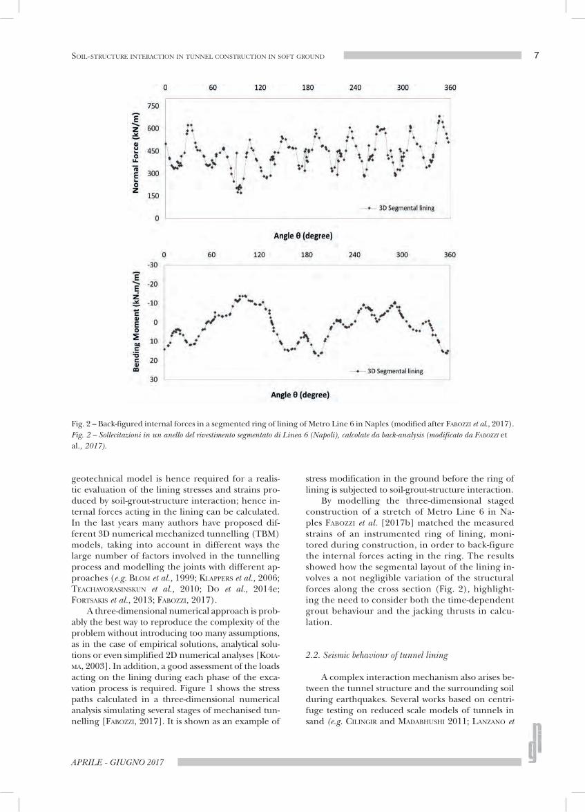
The latter approach requires that an equiva-lence must be established between the simplified model of the building to be considered in the in-teraction analysis and the detailed model to be used in the structural analysis. A possible procedure to achieve such an equivalence was proposed by LOSAC-CO et al. [2014]. They define an equivalent solid for a masonry building from the bearing façades. This sol-id has the same shape as the embedded part of the building and height Heq. It has a cross-anisotropic linear elastic behaviour with a vertical axis of symme-try. The proposed identification procedure requires that the same hogging profile of displacement is imposed to both the equivalent solid and the com-plete façade. The equivalence is based on the shear force, calculated as resultant of the nodal forces in the structure. The shear force distribution along the wall is assumed as target. Openings in the façade are initially taken into account according to the proce-dure suggested by PICKHAVER et al. [2010] to evaluate area and second moment of area, A and I, for the façade in the detailed model.
Hence the elastic parameters of the cross-aniso-tropic solid are calculated as follows:
E E=*v (17a)
E EII=*
h eq (17b)
G GAA=*
vheq
(17c)
v = =hh v vhv (17d)
where E, G and ν are the elastic parameters of the detailed model of the façade, that is assumed as line-ar elastic, and Aeq and Ieq indicate the area and sec-ond moment of area of the equivalent solid of height Heq. The starred symbols refer to the initial trial properties of the equivalent solid.
Later, optimisation is performed by reducing the difference between the distribution of shear force calculated in the complete structure and that on the initial equivalent solid. This is achieved by re-ducing the elastic moduli by the same factor α (Fig. 8).
According to LOSACCO et al. [2014] the factor α depends on the number of openings, on the ra-tio H/L between the height and the length of the
Fig. 8 – Identification procedure of an equivalent solid (modified after LOSACCO et al., 2014).Fig. 8 – Procedura d’identificazione di un solido equivalente (modificata da LOSACCO et al., 2014).

RIVISTA ITALIANA DI GEOTECNICA
16 BILOTTA
façade, and on the ratio L/Heq. They show that α reduces when increasing the height H of the façade, since the upper portion of the building does not contribute significantly to the stiffness optimisation of the equivalent solid, while it increases with Heq, being smaller the reduction to apply when the em-bedded part of the building is smaller.
Hence the whole building can be modelled by means of the equivalent solids relevant to the façades and the internal bearing walls.
For low values of volume loss induced by tunnel-ling and good quality masonry, the hypothesis that the masonry remains in elastic conditions may be reasonable. However, this may not be the case when the yielding and cracking occur. Nevertheless, the equivalent solid approach assumes that soil-struc-ture interaction is not influenced by non-linear be-haviour. In this case non-linearity of masonry is mod-elled in the refined structural model of the build-ing only. Such an approach was for instance adopted for the damage assessment of the Basilica di Massen-zio, that is located in the outstanding archaeological area of the Fori Imperiali in Rome along the path of a stretch of the new Metro Line C (twin tunnels, D=10 m) currently under design [BURGHIGNOLI, 2011; RAMPELLO et al., 2012]. An equivalent solid was de-fined for the Basilica and two finite element models were analysed (Fig. 9): a geotechnical model of in-teraction between tunnelling and the equivalent sol-id, where the displacements at the foundation level were calculated assuming a volume loss V’=0.6%; a detailed structural model where the calculated dis-placements were applied to assess the induced stress-es and strains in the masonry building. The structur-al analysis [BURGHIGNOLI, 2011] showed that before tunnelling, the calculated maximum tensile strain induced by the building self-weight is slightly lower than 10-3, while after tunnelling it increases to slight-ly more than 10-3 (Fig. 10). Although the distribution of strain clearly changes due to tunnelling induced displacements, such a low increase of maximum ten-sile strain would be associated to negligible effects in the masonry. The analysis shows instead the impor-tance of defining pre-existing conditions of masonry for a final assessment of damage. The damage pre-diction improves by using computational approach-es including plastic or cracking models for the ma-sonry (e.g. ROTS 2000; SON and CORDING, 2007; GIAR-DINA, 2013; GIARDINA et al., 2013; AMOROSI et al., 2014).
Fig. 9 – Procedure adopted for the damage assessment of the Basilica di Massenzio in Rome (modified after BURGHI-GNOLI, 2011).Fig. 9 – Procedura adottata per la valutazione del danno potenziale alla Basilica di Massenzio a Roma (modificata da BURGHIGNOLI, 2011).
Fig. 10 – Strain distribution in the refined structural model of the Basilica di Massenzio (modified after BURGHIGNOLI, 2011).Fig. 10 – Campo di deformazione calcolato nel modello strutturale di dettaglio della Basilica di Massenzio (modificata da BURGHIGNOLI, 2011).

17
APRILE - GIUGNO 2017
SOIL-STRUCTURE INTERACTION IN TUNNEL CONSTRUCTION IN SOFT GROUND
Several examples show the importance of ma-sonry modelling and characterization when deal-ing with tunnelling in historic urban areas. Here an-cient and monumental buildings are made of aged masonry, and their mechanical properties have to be determined. An enlightening case is that of the Felice aqueduct, again in Rome [AMOROSI et al., 2014]. This is a historical masonry construction built in 1585 on the ruins of Circo Variano, a Ro-man amphitheatre dating back to the third centu-ry B.C. The original mixed tuff blocks and bricks masonry was partially substituted with arches made of bricks at the beginning of the twentieth century (Fig. 11). It is a typical case showing how difficult can be the identification of the structure and ma-terials of an existing historical building. The Felice aqueduct is underpassed by the twin tunnels of the new Metro Line C, hence the need to assess the ef-fect on the masonry structure of the displacement field induced by tunnelling.
AMOROSI et al. [2014] characterize the masonry with a macroscopic approach, assuming a periodic texture with anisotropic behaviour. The macroscop-ic model for block masonry, formulated in the con-text of continuum infinitesimal rate-independent elasto-plasticity, depends on a limited number of ge-ometrical and mechanical parameters [DE FELICE et al., 2010].
Both uncoupled and coupled approaches were used by the Authors to assess the level of damage in-duced on the structure by 2D finite element analysis, assuming a volume loss V’≅0.5%. In the second case, the whole system consisting of the Felice aqueduct,
the Circo Variano and the ground was incorporated in the model.
The coupled analysis results in less intense ten-sile plastic strains in the masonry of the Felice aque-duct. Calculated tensile plastic strain were almost ex-clusively cumulated in the Circo Variano with a max-imum value of 0.05%, corresponding to a negligible to very slight level of damage.
This clearly indicated that the presence of the massive Circo Variano, functioning as a stiff founda-tion for the aqueduct, reduces the horizontal strain and avoids significant damage.
However, it must be noted that available evi-dences from numerical analyses show [LIU, 1997] that when masonry cracks, the soil structure inter-action itself is influenced. Arching may occur and the masonry structure may then behave as a set of independent rigid blocks. This can be observed in the settlement profile beneath an arching masonry (Fig. 12). Due to the presence of arches, the pres-sure on the ground from the façade is redistribut-ed: the soil under the arches will settle more, thus leading the settlement trough to become locally flat. In addition, the horizontal component of arch-ing may easily cause horizontal tensile strain in the foundation soil thus producing vertical cracks in the façade.
This evidence shows the importance of the cracking and post-cracking behaviour of mason-ry on soil-structure interaction affecting tunnel-ling-induced displacements. LIU et al. [2001] mod-elled the problem using a non-linear elastic no ten-sion model in which material under compression
Fig. 11 – Felice aqueduct in Rome and underpassing tunnels of Line C (modified after AMOROSI et al., 2014).Fig. 11 – Acquedotto Felice a Roma e gallerie della linea C sottostanti (modificato da AMOROSI et al., 2014).

RIVISTA ITALIANA DI GEOTECNICA
18 BILOTTA
behaves elastically, while material in tension will crack where tensile stress develops. A macroscopic approach is used where masonry is treated as a con-tinuum. Moreover, a smeared cracking approach is adopted, where the cracked masonry is assumed to remain as a continuum (i.e. cracks are not mod-elled individually). Cracking involves a reduction of stiffness to a small value (Fig. 13) in the direction of the maximum tensile stress (i.e. perpendicular to the first crack). Three states are defined in the constitutive model [LIU, 1997]: elastic intact, single cracked and double cracked; each of them has its own stiffness matrix.
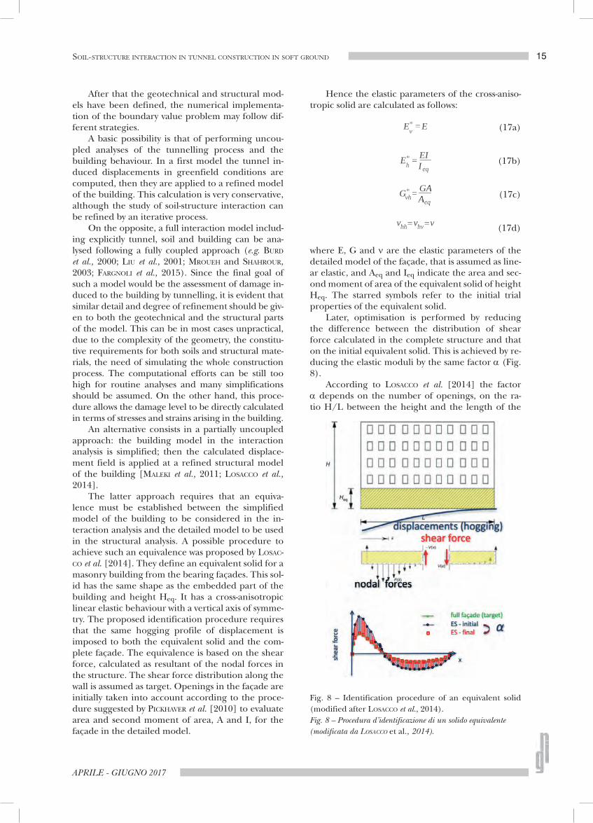
In the result of their work the masonry was ob-served to form arches in sagging regions. The stress redistribution due to the arching resulted in re-duced differential settlement. Significant crack dam-age occurred under the arch, but very little above it due to its supporting action. No significant arching was evident instead in hogging (Fig. 14).
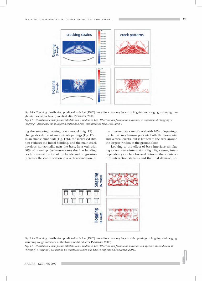
The presence of openings in the façade leads the cracks to concentrate at the corners of the windows. Moreover, damage spreads over larger areas of the façade, the higher the number of openings (Fig. 15).
Different models, including crack constitutive law with tension softening, may simulate cracking evolution and the progressive building damage dur-ing tunnelling.
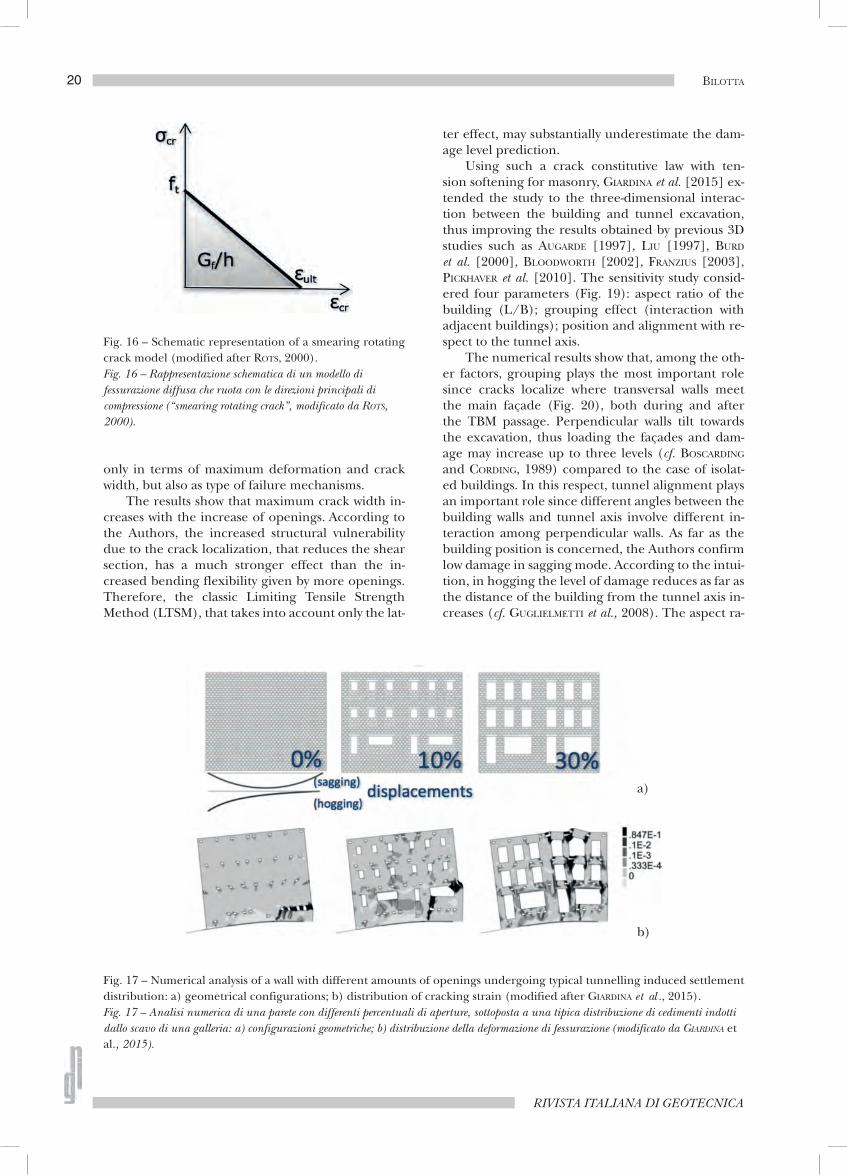
GIARDINA et al. [2013; 2015], for instance, ana-lysed the behaviour of a masonry panel undergoing typical profiles of ground movements induced by tunnelling. They modelled the masonry behaviour with a smearing rotating crack model [ROTS, 2000]. In the adopted continuum, the tension behaviour af-ter cracking is defined by the tensile strength ft, the fracture energy Gf and the crack bandwidth h (Fig. 16).
They showed that when using an elastic mod-el, the localisation of the maximum tensile strains could differ from the actual crack location observed in experimental tests [GIARDINA et al., 2012] and from the numerical results obtained by using a cracking model. This confirms the need to include the crack-ing-induced stress redistribution in the structure evaluation.
Cracking localization in hogging can be observed in the numerical results by GIARDINA et al. [2015] us-
Fig. 12 – Soil-structure interaction of a cracked masonry façade (modified after LIU, 1997).Fig. 12 – Interazione terreno-struttura di una facciata in muratura lesionata (modificata da LIU, 1997).
Fig. 13 – Schematic representation of an elastic no tension model (modified after LIU, 1997).Fig. 13 – Rappresentazione schematica di un modello elastico in compressione e con scarsa resistenza a trazione (“elastic no tension”, modificato da LIU, 1997).
19
APRILE - GIUGNO 2017
SOIL-STRUCTURE INTERACTION IN TUNNEL CONSTRUCTION IN SOFT GROUND
ing the smearing rotating crack model (Fig. 17). It changes for different amounts of openings (Fig. 17a). In an almost blind wall (Fig. 17b), the increased stiff-ness reduces the initial bending, and the main crack develops horizontally, near the base. In a wall with 30% of openings (reference case) the first bending crack occurs at the top of the facade and progressive-ly crosses the entire section in a vertical direction. In
the intermediate case of a wall with 10% of openings, the failure mechanism presents both the horizontal and vertical cracks, but is limited to the area around the largest window at the ground floor.
Looking to the effect of base interface simulat-ing soil-structure interaction (Fig. 18), a strong inter-dependency can be observed between the soil-struc-ture interaction stiffness and the final damage, not
Fig. 14 – Cracking distribution predicted with LIU [1997] model in a masonry façade in hogging and sagging, assuming rou-gh interface at the base (modified after PICKHAVER, 2006).Fig. 14 – Distribuzione delle fessure calcolata con il modello di LIU [1997] in una facciata in muratura, in condizioni di “hogging” e “sagging”, assumendo un’interfaccia scabra alla base (modificata da PICKHAVER, 2006).
Fig. 15 – Cracking distribution predicted with LIU [1997] model in a masonry façade with openings in hogging and sagging, assuming rough interface at the base (modified after PICKHAVER, 2006).Fig. 15 – Distribuzione delle fessure calcolata con il modello di LIU [1997] in una facciata in muratura con aperture, in condizioni di “hogging” e “sagging”, assumendo un’interfaccia scabra alla base (modificata da PICKHAVER, 2006).
RIVISTA ITALIANA DI GEOTECNICA
20 BILOTTA
only in terms of maximum deformation and crack width, but also as type of failure mechanisms.
The results show that maximum crack width in-creases with the increase of openings. According to the Authors, the increased structural vulnerability due to the crack localization, that reduces the shear section, has a much stronger effect than the in-creased bending flexibility given by more openings. Therefore, the classic Limiting Tensile Strength Method (LTSM), that takes into account only the lat-
ter effect, may substantially underestimate the dam-age level prediction.
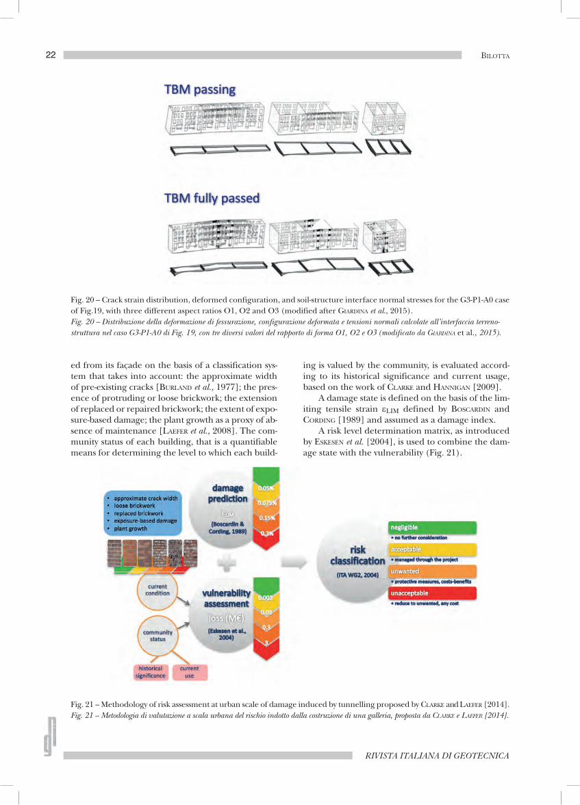
Using such a crack constitutive law with ten-sion softening for masonry, GIARDINA et al. [2015] ex-tended the study to the three-dimensional interac-tion between the building and tunnel excavation, thus improving the results obtained by previous 3D studies such as AUGARDE [1997], LIU [1997], BURD et al. [2000], BLOODWORTH [2002], FRANZIUS [2003], PICKHAVER et al. [2010]. The sensitivity study consid-ered four parameters (Fig. 19): aspect ratio of the building (L/B); grouping effect (interaction with adjacent buildings); position and alignment with re-spect to the tunnel axis.
The numerical results show that, among the oth-er factors, grouping plays the most important role since cracks localize where transversal walls meet the main façade (Fig. 20), both during and after the TBM passage. Perpendicular walls tilt towards the excavation, thus loading the façades and dam-age may increase up to three levels (cf. BOSCARDING and CORDING, 1989) compared to the case of isolat-ed buildings. In this respect, tunnel alignment plays an important role since different angles between the building walls and tunnel axis involve different in-teraction among perpendicular walls. As far as the building position is concerned, the Authors confirm low damage in sagging mode. According to the intui-tion, in hogging the level of damage reduces as far as the distance of the building from the tunnel axis in-creases (cf. GUGLIELMETTI et al., 2008). The aspect ra-
Fig. 17 – Numerical analysis of a wall with different amounts of openings undergoing typical tunnelling induced settlement distribution: a) geometrical configurations; b) distribution of cracking strain (modified after GIARDINA et al ., 2015).Fig. 17 – Analisi numerica di una parete con differenti percentuali di aperture, sottoposta a una tipica distribuzione di cedimenti indotti dallo scavo di una galleria: a) configurazioni geometriche; b) distribuzione della deformazione di fessurazione (modificato da GIARDINA et al., 2015).
Fig. 16 – Schematic representation of a smearing rotating crack model (modified after ROTS, 2000).Fig. 16 – Rappresentazione schematica di un modello di fessurazione diffusa che ruota con le direzioni principali di compressione (“smearing rotating crack”, modificato da ROTS, 2000).
a)
b)

21
APRILE - GIUGNO 2017
SOIL-STRUCTURE INTERACTION IN TUNNEL CONSTRUCTION IN SOFT GROUND
tio between the building dimensions in plan (L/B) plays a very marginal role in this problem.
3.1.4. EVOLUTION OF RISK ASSESSMENT PROCEDURES AT UR-BAN SCALE
The importance of considering the current con-dition of the building when modelling soil-structure interaction in a tunnelling-induced displacement problem has been discussed in the previous section, for historic and heritage masonry buildings. It has been also pointed out that when dealing this problem at the urban scale, however, soil-structure interaction tends to be neglected. Hence the influence of the cur-rent state of the building has been often neglected
in methodologies of damage assessment that assume wholly undamaged structures before tunnelling.
More recently CLARKE and LAEFER [2014] have proposed that both physical conditions and cultural aspects should be incorporated in building vulner-ability criteria, in risk assessment procedures at the urban scale. They propose a methodology of damage assessment that is similar to that commonly adopt-ed for seismic risk analyses where a building’s vul-nerability is assessed not only on the basis of to the expected physical damage but also according to so-cio-economic aspects and resiliency conditions (e.g. CARDONA and HURTADO, 2000; CARRENO et al., 2007).
In CLARKE and LAEFER [2014] methodology, the current physical condition of the building is evaluat-
Fig. 18 – Influence on cracking strain of different normal stiffness kn of the interface that models the foundation (modified after GIARDINA et al., 2015).Fig. 18 – Influenza sulla deformazione di fessurazione calcolata di differenti valori di rigidezza normale kn dell’interfaccia che modella la fondazione (modificato da GIARDINA et al., 2015).
Fig. 19 – Parameters that affect the 3D soil-structure interaction (modified after GIARDINA et al., 2015).Fig. 19 – Parametri che influenzano l’interazione 3D terreno-struttura (modificato da GIARDINA et al., 2015).
RIVISTA ITALIANA DI GEOTECNICA
22 BILOTTA
ed from its façade on the basis of a classification sys-tem that takes into account: the approximate width of pre-existing cracks [BURLAND et al., 1977]; the pres-ence of protruding or loose brickwork; the extension of replaced or repaired brickwork; the extent of expo-sure-based damage; the plant growth as a proxy of ab-sence of maintenance [LAEFER et al., 2008]. The com-munity status of each building, that is a quantifiable means for determining the level to which each build-
ing is valued by the community, is evaluated accord-ing to its historical significance and current usage, based on the work of CLARKE and HANNIGAN [2009].
A damage state is defined on the basis of the lim-iting tensile strain εLIM defined by BOSCARDIN and CORDING [1989] and assumed as a damage index.
A risk level determination matrix, as introduced by ESKESEN et al. [2004], is used to combine the dam-age state with the vulnerability (Fig. 21).
Fig. 21 – Methodology of risk assessment at urban scale of damage induced by tunnelling proposed by CLARKE and LAEFER [2014].Fig. 21 – Metodologia di valutazione a scala urbana del rischio indotto dalla costruzione di una galleria, proposta da CLARKE e LAEFER [2014].
Fig. 20 – Crack strain distribution, deformed configuration, and soil-structure interface normal stresses for the G3-P1-A0 case of Fig.19, with three different aspect ratios O1, O2 and O3 (modified after GIARDINA et al., 2015).Fig. 20 – Distribuzione della deformazione di fessurazione, configurazione deformata e tensioni normali calcolate all’interfaccia terreno-struttura nel caso G3-P1-A0 di Fig. 19, con tre diversi valori del rapporto di forma O1, O2 e O3 (modificato da GIARDINA et al., 2015).

23
APRILE - GIUGNO 2017
SOIL-STRUCTURE INTERACTION IN TUNNEL CONSTRUCTION IN SOFT GROUND
Such kind of methodology has the potential to incorporate further building vulnerability crite-ria, developed on the basis of soil-structure inter-action studies (e.g. GIARDINA et al., 2015), such as percentage of opening, foundation system, group-ing effect.
Soil-structure interaction assumes therefore a relevance non only at the scale of the single building or of a cluster of buildings, but also at a larger scale, that of the urban built environment, where it is gen-erally neglected.
3.2. Seismic interaction in urban underground space
Further examples can be shown where soil-struc-ture interaction is involved at the urban scale. That is for instance when considering “city effects” in the seismic behaviour of tunnels.
It is worth noting that wave propagation during earthquakes in a densely urbanised environment is
more complex than in ideal free-field conditions. The presence of structures both in the ground and above the ground surface affects wave propagation. Hence, reciprocal influence arises among different structures (structure-soil-structure) and between the seismic re-sponses of the underground space (with tunnels, foundations and deep excavations) and of the built surface (with high-rise buildings in particular). These are known as Seismic Site-City interaction [KHAM et al. 2006] or City Effects [GHERGU and IONESCU, 2009]. A review was recently presented by LOU et al. [2011] on the history and status of the structure-soil-structure dynamic interaction research. Geotechnical research on tunnels under seismic conditions is recently in-cluding also this complex problem of soil-structure interaction.
PITILAKIS et al. [2014] carried out dynamic numer-ical analyses of tunnels in the transversal direction, with the surface structures been simulated as equiva-lent single degree of freedom (SDOF) oscillators with rigid foundations. Their results show that in most cas-
Fig. 22 – Centrifuge tests on dynamic building-soil-tunnel interaction: a) schematic drawings of the experimental program-me; b) layout of instrumentation (modified after DASHTI et al., 2016).Fig. 22 – Prove in centrifuga su interazione dinamica edificio-terreno-galleria: a) schemi del programma sperimentale; b) schemi di strumentazione (modificato da DASHTI et al., 2016).
a)
b)

RIVISTA ITALIANA DI GEOTECNICA
24 BILOTTA
es the presence of the above ground structures results in an increase of both ovalisation and lining forces in the tunnel during seismic shaking, being this effect more significant for shallower tunnels.
DASHTI et al. [2016] carried out centrifuge tests (Fig. 22) showing that the presence of an adjacent high-rise building slightly reduces racking displace-ments on an underground box structure, but it in-creases seismic lateral earth pressures on the build-ing side of the tunnel.
A parametric numerical finite element analy-ses of a full-coupled tunnel-soil-aboveground build-ing system was carried out by ABATE and MASSIMINO [2017] in real site conditions. Their results showed that up to certain distance between the tunnel and the building the seismic response of the system is af-fected by the presence of the building: if de-amplifi-cation at ground surface occurs, tunnels in urban ar-eas may have beneficial effects.
Overall, the picture in the case of struc-ture-soil-structure dynamic interaction (SSSI) be-tween tunnels and buildings in urban underground space appears not yet complete. The importance of further studies about SSSI phenomena and their in-fluence on structural seismic risk is however evident, since according to existing evidences nearby build-ings can affect the seismic response of an under-ground structure and vice-versa.
4. Conclusions
Current trends of research in the field of soil-structure interaction in tunnel construction in soft ground have been presented in this paper, where the scale of models ranges from single ele-ment to boundary value problems and towards a larger urban scale. Attention was given to the calcu-lation of the internal forces in the segmental lining structure of a tunnel and to the interaction between shallow tunnel and existing buildings, also in pres-ence of seismic actions.
It has been shown that the analysis of such soil-structure interaction problems first requires a clear understanding of the mechanical behaviour of the system, consisting of structural sub-systems in of-ten complex ground conditions. Then a sound defi-nition of the numerical model to be used in calcula-tions can be achieved.
In “model” definition, the interdisciplinary na-ture of the underground construction emerges with force, requiring a strong interaction between geo-technical engineering and structural engineering, as shown within the conceptual framework of BUR-LAND [2006]. As a matter of fact, the geotechnical engineer that needs to build the appropriate mod-el for his boundary value problem has often to deal
with a geometrical configuration (ground profile) and mechanical properties (soil behaviour) that are not “specified” but assigned by nature. On the other hand, it is generally true that in most cases, namely when dealing with new constructions, the structur-al engineer works with materials that have assigned properties and that are produced with controlled procedures. Moreover, the structural shapes are usu-ally easy to be schematized.
As BURLAND [2006] observed, this is not howev-er the case when the structural engineer intervenes on an existing building. In this case the properties of the materials, for instance an ancient masonry, are not specified: they need to be determined, as for soils, on the basis of experimental observation (in laboratory or on site). Furthermore the geomet-ric configuration of the structure is more complex, sometimes unknown. It needs to be identified, be-fore to be modelled: similarly to the definition of the ground profile, that needs investigations prior to modelling.
Looking back to the research topics and trends that have been discussed in this work, it seems then ----construction, the two disciplines already concur to an advanced stage of interdisciplinarity since they in-tegrate knowledge and methods, using a real synthe-sis of approaches.
Looking to such trends in perspective, it is easy to foresee that research will face several challenges in the next decades, where geotechnical engineer-ing problems meet societal and environmental is-sues. Tunnel construction will possibly provide solu-tions to some of them, offering at the same time ap-pealing opportunities for interdisciplinary research and technological innovation.
Acknowledgements
This work stems from ideas and discussions shared with many researchers over several years of activity on geotechnical aspects of tunnels and un-derground construction. It would be difficult to mention them all: many are listed as authors of the reference papers. I wish here to express gratitude to each and every one of them, and a special thanks to Carlo Viggiani that has always been an enlightening source of inspiration.
References
ABATE G., MASSIMINO M.R. (2017) – Numerical model-ling of the seismic response of a tunnel-soil-aboveground building system in Catania (Italy). Bulletin of Earth-quake Engineering, 15, n. 1, pp . 469-491.

25
APRILE - GIUGNO 2017
SOIL-STRUCTURE INTERACTION IN TUNNEL CONSTRUCTION IN SOFT GROUND
ABATE G., MASSIMINO M.R., MAUGERI M. (2015) – Nu-merical modelling of centrifuge tests on tunnel-soil sys-tems. Bulletin of Earthquake Engineering, 13, n. 7, pp. 1927-1951.
ADDENBROOKE T.I., POTTS D.M., PUZRIN A.M. (1997) – The influence of pre-failure soil stiffness on the numer-ical analysis of tunnel construction. Géotechnique, 47, n. 3, pp. 693-712.
AL-TABBAA A. (1987) – Permeability and stress-strain re-sponse of Speswhite kaolin. PhD Thesis, University of Cambridge.
AMOROSI A., BOLDINI D., DE FELICE G., MALENA M., SE-BASTIANELLI M. (2014) – Tunnelling-induced deforma-tion and damage on historical masonry structures. Géo-technique, 64, n. 2, pp.118-130.
AMOROSI A., BOLDINI D., FALCONE G. (2014) – Numer-ical prediction of tunnel performance during centrifuge dynamic tests. Acta Geotechnica, 9, n. 4, pp. 581-596.
ARGYROUDIS S.A., PITILAKIS K.D. (2012) – Seismic fra-gility curves of shallow tunnels in alluvial deposits. Soil Dynamics and Earthquake Engineering, 35, pp. 1-12.
ARNAU O., MOLINS C. (2012) – Three dimensional struc-tural response of segmental tunnel linings. Engineer-ing Structures, 44, pp.210-221.
ATTEWELL P.B., WOODMAN J.P. (1982) – Predicting the dynamics of ground settlement and its derivatives caused by tunnelling in soil. Ground Engineering,15, n. 7, pp. 13-22.
AUGARDE C.E. (1997) – Numerical modelling of tun-nelling processes for assessment of damage to buildings. PhD Thesis, Oxford University.
AVERSA S. (1997) – Aspetti sperimentali e modellazione nella progettazione delle opere di sostegno e degli scavi. In: Il modello geotecnico del sottosuolo nella pro-gettazione delle opere di sostegno e degli scavi, IV CNRU del GNCSIG-CNR, vol. II, pp. 121-207.
BEZUIJEN A., TALMON A.M., KAALBERG F.J., PLUGGE R. (2004) – Field measurements of grout pressure during tunnelling of Sophia rail tunnel. Soil and foundation, 44, n. 1, pp. 38-48, Japanese Geotechnical Society.
BILOTTA E., RUSSO G. (2013) – Internal forces arising in the segmental lining of an earth pressure balance-bored tunnel. J. Geot. Geoenv. Engn., 139, n. 10, pp. 1765-1780.
BILOTTA E., LANZANO G., MADABHUSHI S.P.G., SILVES-TRI F. (2014) – A numerical Round Robin on tunnels under seismic actions. Acta Geotechnica, 9, n. 4, pp. 563-579.
BILOTTA E., PAOLILLO A., RUSSO G., AVERSA S. (2017) – Displacements induced by tunnelling under a histor-ical building. Tunnelling and Underground Space Technology, 61, pp. 221-232.
BILOTTA E., RUSSO G., VIGGIANI C. (2005) – Ground movements and lining strains during an underground tunnel construction in cohesionless soil in Naples. Proc. Int. Conf. on Soil-structure interaction: calcula-
tion methods and engineering practice, V.M. Ulit-sky (Ed.), 1, pp. 59-64. ASV San Petersburg-Mos-cow.
BILOTTA E., SILVESTRI F. (2012) – A predictive exercise on the behaviour of tunnels under seismic actions. In : Pro-ceedings of the 7th International Symposium on Geotechnical Aspects of Underground Construc-tion in Soft Ground, pp. 1071-1077.
BILOTTA E., MAIORANO R.M.S., VIGLIONE A., AVERSA S. (2015) – Three-dimensional numerical modelling of cir-cular tunnels under seismic actions. COMPDYN 2015 – 5th ECCOMAS Thematic Conference on Com-putational Methods in Structural Dynamics and Earthquake Engineering, pp. 2828-2837.
BLOM C.B.M. (2002) – Design philosophy of concrete lin-ings for tunnels in soft soils. PhD Thesis, TU Delft.
BLOM C.B.M., VAN DER HORST E.J., JOVANOVIC P.S. (1999) – Three-dimensional structural analyses of the shield-driven ‘‘Green Heart’’ tunnel of the high-speed line South. Tunn. Undergr. Space Technol., 14, n. 2, pp. 217-22.
BLOODWORTH A.G. (2002) – Three-dimensional analysis of tunnelling effects on structures to develop design meth-ods. PhD Thesis, University of Oxford.
BOBET A. (2010) – Drained and undrained response of deep tunnels subjected to far-field shear loading. Tunn. Undergr. Space Technol., 25, pp. 21-31.
BOONYARAK T., NG C.W.W. (2014) – Effects of construc-tion sequence and cover depth on crossing-tunnel inter-action. Canadian Geotechnical J., 52, n. 7, pp. 851-867.
BOSCARDIN M.D., CORDING E.G. (1989) – Building re-sponse to excavation induced settlement. J. Geotech. Engng., 115, n. 1, pp. 1-21.
BROERE W. (2016) – Urban underground space: Solving the problems of today’s cities. Tun. & Undergr. Space Tech., 55, pp. 245-248.
BURD H.J., HOULSBY G.T., AUGARDE C.E. (2000) – Modelling tunnelling-induced settlement of masonry buildings. Proc. ICE Geotechnical Engineering, 143, January, pp.17-29.
BURGHIGNOLI A. (2011) – L’attraversamento sotterraneo del centro storico di Roma. Rivista Italiana di Geotec-nica, 45, n. 4, pp. 13-50.
BURLAND J. B. (1995) – Assessment of risk of damage to buildings due to tunnelling and excavation. Proc. 1st Int. Conf. on Earthquake Geotechnical Engineer-ing, IS Tokyo 95, vol. III., pp. 1189-1202.
BURLAND J.B. (2006) – Interaction between structural and geotechnical engineers. The Structural Engineer, 84, pp. 29-37.
BURLAND J.B., WROTH C.P. (1974) – Settlement of build-ing and associate damage. Proc. Conf. on Settlement of Structures, Cambridge, pp. 611-654.
BURLAND J.B., BROMS B.B, DE MELLO V.F.B. (1977) – Behaviour of foundations and structures. State of the art report, Session 2, Proc. 9th ICSMFE, Tokyo, 2, pp. 495-546.

RIVISTA ITALIANA DI GEOTECNICA
26 BILOTTA
BURLAND J.B., MAIR R.J., STANDING J.R. (2004) – Ground performance and building response due to tun-nelling. In: Advances in Geotechnical Engineer-ing: The Skempton Conference – Proceedings of a Three Day Conference on Advances in Geotech-nical Engineering, organised by the Institution of Civil Engineers, pp. 291-344.
BURNS J.Q., RICHARD R.M. (1964) – Attenuation of stresses for buried cylinders. Proc. of the Symposium on Soil-Structure Interaction, pp. 278-392.
CARDONA O. D., HURTADO J. E. (2000) – Holistic seis-mic risk estimation of a metropolitan center. In: Pro-ceedings of 12th World Conference of Earthquake Engineering, Auckland, New Zeland.
CARREÑO M.L., CARDONA O.D., BARBAT A.H. (2007) – Urban Seismic Risk Evaluation: A Holistic Approach. Nat Hazards, 40, p. 137.
CAVALARO S., AGUADO A. (2011) – Packer behaviour un-der simple and coupled stresses. Tunn. Undergr. Space Technol., 28, pp. 159-173.
CILINGIR U., MADABHUSHI S.P.G. (2011) – Effect of depth on the seismic response of circular tunnels. Can Geotech J., 48, n. 1, pp. 117-127.
CLARKE J., HANNIGAN L. (2009) – A three-stage assess-ment process to predict risk levels due to subsurface con-struction. In: Proceedings of 34th Annual Confer-ence on Deep Foundations, Kansas City, Publica-tion, n. 89 (AM-2009).
CLARKE J. A., LAEFER D. F. (2014) – Evaluation of risk assessment procedures for buildings adjacent to tunnel-ling works. Tunnelling Underground Space Tech-nol., 40, pp. 333-342.
CONTI R., VIGGIANI G.M.B., PERUGINI F. (2014) – Nu-merical modelling of centrifuge dynamic tests of circular tunnels in dry sand. Acta Geotechnica, 9, n. 4, pp. 597-612.
DASHTI S., HASHASH Y.M.A., GILLIS K., MUSGROVE M., WALKER M. (2016) – Development of dynamic centri-fuge models of underground structures near tall build-ings. Soil Dynamics and Earthquake Engineering, 86, pp. 89-105.
DE FELICE G., AMOROSI A., MALENA M. (2010) – Elas-to-plastic analysis of block structures through a ho-mogenization method. Int. J. Numer. Anal. Meth. Geomech., 34, pp. 221-247.
DING J.H., JIN X.L., GUO Y.Z., LI G.G. (2006) – Nu-merical simulation for large-scale seismic response analy-sis of immersed tunnel. Eng. Struct. 28, n. 1 pp. 1367-77.
DO N.-A., DIAS D., ORESTE P., DJERAN-MAIGRE I. (2014a) – Three-dimensional numerical simulation of a mechanized twin tunnels in soft ground. Tunnelling and Underground Space Technology, 42, pp. 40-51.
DO N.-A., DIAS D., ORESTE P., DJERAN-MAIGRE I. (2014d) – The behaviour of the segmental tunnel lin-ing studied by the hyperstatic reaction method. Europe-an Journal of Environmental and Civil Engineer-
ing, 18, n. 4, pp. 489-510. DO N.-A., DIAS D., ORESTE P., DJERAN-MAIGRE I.
(2014e) – Three-dimensional numerical simulation for mechanized tunnelling in soft ground: The influence of the joint pattern. Acta Geotechnica, 9. n. 4, pp. 673-694.
DO N.A., DIAS D., ORESTE P., DJERAN-MAIGRE I. (2014b) – A new numerical approach to the hyperstatic reaction method for segmental tunnel linings. Interna-tional Journal for Numerical and Analytical Meth-ods in Geomechanics, 38, n. 15, pp. 1617-1632.
DO N.A., DIAS D., ORESTE P.P., DJERAN-MAIGRE I. (2014c) – Internal forces in segmental tunnel linings – a comparison between current design methods. Journal of Mining Science, 50, n. 2, pp. 326-334.
ESKESEN S.D., TENGBORG P., KAMPMANN J., HOLST VEICHERTS T. (2004) – Guidelines for tunnelling risk management: International Tunnelling Associa-tion, Working Group No. 2. Tunnelling and Under-ground Space Technology, 19, n. 3, pp. 217-237.
FABOZZI S. (2017) – Behaviour of segmental tunnel lin-ing under static and dynamic loads. PhD Thesis. Uni-versity of Napoli Federico II.
FABOZZI S., BILOTTA E. (2016) – Behavior of a segmen-tal tunnel lining under seismic actions. Procedia En-gineering, 158, pp. 230-235.
FABOZZI S., BILOTTA E., LANZANO G., (2017a) – A nu-merical study on seismic vulnerability of tunnel linings. Proc. III PBD Vancouver, 2017.
FABOZZI S., BILOTTA E., RUSSO G. (2016) – Numerical interpretation of monitoring data of an instrumented tunnel segmental ring. Proc. 1st IMEKO TC4, Metro-Geotechnics, 2016, pp. 350-355.
FABOZZI S., BILOTTA E., RUSSO G. (2017b) – Numeri-cal back-calculation of strain measurements from an in-strumented segmental tunnel lining. In : Proc. IV Int. Conf. on Computational Methods in tunnelling and Subsurface Engineering, EURO:TUN 2017, pp. 617-624. Leopold-Franzens-Universität Inns-bruck, Austria.
FARGNOLI V., GRAGNANO C.G., BOLDINI D., AMOROSI A. (2015) – 3D numerical modelling of soil-structure in-teraction during EPB tunnelling. Géotechnique, 65, n. 1, pp. 23-37.
FORTSAKIS P., LITSAS D., KAVVADAS M. (2013) – Reli-ability analysis of unreinforced tunnel final lining. Proc. EURO:TUN 2013, 3rd International Confer-ence on Computational Methods in Tunnelling and Subsurface Engineering, Ruhr University Bo-chum, 17-19 April 2013.
FRANZIUS J.N. (2003) – Behaviour of buildings due to tunnel induced subsidence. PhD Thesis, Imperial College London, UK.
GHERGU M., IONESCU I.R. (2009) – Structure-soil-struc-ture coupling in seismic excitation and “city effect”. Int. Journal of Engineering Science, 47, n. 3, pp. 342-354.
GIARDINA G., HENDRIKS M.A.N., ROTS J.G. (2015) –

27
APRILE - GIUGNO 2017
SOIL-STRUCTURE INTERACTION IN TUNNEL CONSTRUCTION IN SOFT GROUND
Damage functions for the vulnerability assessment of masonry buildings subjected to tunnelling. J. Struct. Eng., 141, n. 9, 04014212.1-13.
GIARDINA G., VAN DE GRAAF A., HENDRIKS M.A.N., ROTS J. G., MARINI A. (2013) – Numerical analysis of a ma-sonry facade subject to tunnelling- induced settlement. Eng. Struct., 54, pp. 234-247.
GIARDINA G. (2013) – Modelling of settlement-induced building damage. Ph.D. Thesis, Delft Univ. of Tech-nology, Delft, Netherlands.
GIARDINA G., MARINI A., HENDRIKS M.A.N., ROTS J. G., RIZZARDINI F., GIURIANI E. (2012) – Experimental analysis of a masonry facade subject to tunnelling-in-duced settlement. Eng. Struct., 45, pp. 421-434.
GOMES R.C. (2014) – Numerical simulation of the seis-mic response of tunnels in sand with an elastoplastic model. Acta Geotechnica, 9, n. 4, pp. 613-629.
GRAMMATIKOPOULOU A., ZDRAVKOVIC L., POTTS D.M. (2006) – General formulation of two kinematic harden-ing constitutive models with a smooth elastoplastic tran-sition. International Journal of Geomechanics, 6, n. 5, pp. 291-302.
GRAMMATIKOPOULOU A., ZDRAVKOVIC L., POTTS D.M. (2008) – The influence of previous stress history and stress path direction on the surface settlement trough induced by tunnelling. Géotechnique, 58, n. 4, pp. 269-281.
GUGLIELMETTI V., GRASSO P., MAHTAB A., XU S. (2008) – Mechanized tunnelling in urban areas: Design meth-odology and construction control. Taylor and Francis, Leiden.
HASHASH Y.M.A., HOOKA J.J., SCHMIDT B., YAO J.I.-C. (2001) – Seismic design and analysis of underground structures. Tunn. and Undergr. Space Technol., 16, pp. 247-293.
HASHASH Y.M.A., PARK D., YAO J.I-C. (2005) – Oval-ing de-formations of circular tunnels under seismic load-ing, an up-date on seismic design and analyses of under-ground structures. Tunn. and Undergr. Space Tech-nol., 20, pp. 435-441.
HATZIGEORGIOU G.D., BESKOS D.E. (2010) – Soil-struc-ture interaction effects on seismic inelastic analysis of 3-D tunnels. Soil Dynamics and Earthquake En-gineering, 30, n. 9, pp. 851-861.
HLEIBIEH J., WEGENER D., HERLE I. (2014) – Numerical simulation of a tunnel surrounded by sand using a hy-poplastic model. Acta Geotech, 9, n. 4, pp. 621-640.
HOEG K. (1968) – Stresses against underground struc-tural cylinders. J. Soil Mech. Found. Div. ASCE, 94 SM4. Pp. 833 858.
HUO H., BOBET A., FERNÁNDEZ G., RAMÍREZ J. (2006) – Analytical solution for deep rectangular structures subjected to far-field shear stresses. Tunnel. Undergr. Space Technol., 21, pp. 613-625.
ROWE R.K., LO K.Y., KACK G.J. (1983) – A method of estimating surface settlement above tunnels constructed in soft ground. Canadian Geotechnical Journal, 20, pp. 11-22.
KHAM M., SEMBLAT J.-F., BARD P.-Y., DANGLA P. (2006) – Seismic site-city interaction: Main governing phenom-ena through simplified numerical models. Bulletin of the Seismological Society of America, 96, n. 5, pp. 1934-1951.
KIYOMIYA O. (1995) – Earthquake-resistant design fea-tures of immersed tunnels in Japan. Tunn. Undergr. Space Technol, 10, n. 4, pp. 463-75.
KLAPPERS C., GRUBL F., OSTERMEIRE B. (2006) – Struc-tural analyses of segmental lining coupled beam and spring analyses versus 3D FEM calculations with shell elements. Tunn. Undergr. Space Technol, 21, pp . 254-25.
KOIAMA Y. (2003) – Present status and technology of shield tunnelling method in Japan. Tunnelling and Underground Space Technology, 18, p p. 145-59.
KONTOE S., AVGERINOS V., POTTS D.M. (2014) – Nu-merical validation of analytical solutions and their use for equivalent-linear seismic analysis of circular tun-nels. Soil Dynamics and Earthquake Engineering, 66, pp. 206-219.
LAEFER D.F, CONRY B., MURPHY D., CERIBASI S. (2008) – A New Multi-Parameter Condition Assessment Scale for Tunnel Risk Estimation. ISMGGE, vol. II, Deve-lopment of Urban Areas and Geotechnical En-gineering, St. Petersburg, pp. 571-576.
LANZANO G. (2009) – Physical and analytical modelling of tunnels under dynamic loadings. PhD Thesis, Uni-versity of Napoli Federico II (Italy).
LANZANO G., BILOTTA E. (2014) – Permanent incre-ments of internal forces on a tunnel lining due to dy-namic loadings. In: Geotechnical Aspects of Un-derground Construction in Soft Ground - Pro-ceedings of the 8th Int. Symposium on Geotechni-cal Aspects of Underground Construction in Soft Ground, TC204 ISSMGE - IS-SEOUL 2014, pp. 203-208.
LANZANO G., BILOTTA E., RUSSO G., SILVESTRI F., MADAB-HUSHI S.P.G. (2012) – Centrifuge modeling of seismic loading on tunnels in sand. Geotech. Test J., 35, n. 6, pp. 854-869.
LI C. (2016) – Seismic Response Analysis and Test of Long Segmental Immersed Tunnel. PhD Thesis, Tong-ji University, Shanghai (China).
LI P., SONG E.-X. (2015) – Three-dimensional numerical analysis for the longitudinal seismic response of tunnels under an asynchronous wave input. Computers and Geotechnics, 63, pp. 229-243.
LI X., YAN Z., WANG Z., ZHU H. (2015) – A progressive model to simulate the full mechanical behaviour of con-crete segmental lining longitudinal joint. Engineering Structures, 93, pp. 97-113.
LIU G. (1997) – Numerical Modelling of damage to ma-sonry buildings due to tunnelling. PhD Thesis Oxford University, UK.
LIU G., HOULSBY G. T., AUGARDE C. E. (2001) – 2-di-mensional analysis of settlement damage to masonry buildings caused by tunnelling. Struct. Engr., 79, n.

RIVISTA ITALIANA DI GEOTECNICA
28 BILOTTA
1, pp. 19-25. LOSACCO N., BURGHIGNOLI A., CALLISTO L. (2014) –
Uncoupled evaluation of the structural damage induced by tunnelling. Géotechnique, 64, n. 8, pp. 646-656.
LOU M., WANG H., CHEN X., ZHAI Y. (2011) – Struc-ture-soil-structure interaction: Literature review. Soil Dynamics and Earthquake Engineering, 31, pp. 1724-1731.
MAIR R.J., TAYLOR R.N., BRACEGIRDLE A. (1993) – Sub-surface settlement profiles above tunnels in clays. Géo-technique, 43. n. 2, pp. 315-320.
MAIR R.J., TAYLOR R.N., BURLAND J.B. (1996) – Pre-diction of ground movements and assessment of risk of building damage due to bored tunnelling. Proc. Int. Symp. Geotech. Aspects Undergr. Constr. in Soft Ground, Balkema, London, pp. 713-718.
MALEKI M., SERESHTEH H., MOUSIVAND M., BAYAT M. (2011) – An equivalent beam model for the analysis of tunnel-building inter-action. Tunnelling Under-ground Space Technol., 26, n. 4, pp. 524-533.
MOH Z.C., HWANG R.N., JU, D.H. (1996) – Ground move-ments around tunnels in soft ground. Geotechnical Aspects of Underground Construction in Soft Ground, Mair and Taylor (Eds.), Balkema, Rotter-dam, pp. 725-730.
MÖLLER S.C. (2006) – Tunnel induced settlements and structural forces in linings. PhD Thesis, University of Stuttgart.
MROUEH H., SHAHROUR I. (2003) – A full 3-D finite el-ement analysis of tunneling-adjacent structures interac-tion. Comput. Geotech. 30, n. 3, pp. 245-253.
O’REILLY M.P., NEW B.M. (1982) – Settlements above tunnels in the United Kingdom – their magnitude and prediction. Proc. Tunnelling ’82 Symp., Insti-tution of Mining and Metallurgy, London, pp., 55-64.
OWEN G.N., SCHOLL R.E. (1981) – Earthquake engineering of large underground structures. Report no. FHWA/RD-80/195. Federal Highway Admin-istration and National Science Foundation, 1981.
PARK D., SAGONG M., KWAK, D-Y, JEONG C-G. (2009) – Simulation of tunnel response under spatially vary-ing ground motion. Soil Dyn. Earthquake, 29, pp. 1417-24.
PARK K.-H., TANTAYOPIN K., TONTAVANICH B., OWATSIRI-WONG A. (2009) – Analytical solution for seismic-in-duced ovaling of circular tunnel lining under no-slip interface conditions: a revisit. Tunn. Undergr. Space Technol. n. 24, pp. 231-235.
PECK R.B. (1969) – Deep excavations and tunnelling in soft ground. Proc. 7th ICSMFE, Mexico City, State of the Art Volume, pp. 225-290.
PECK R.B., HENDRON A.J., MOHRAZ B. (1972) – State of the art in soft ground tunnelling. Proc. of the Rapid Excavation and Tunnelling Conference, Ameri-can Institute of Mining, Metallurgical and Petro-leum Engineers, New York, pp. 259-286.
PENZIEN J. (2000) – Seismically -induced racking of tun-
nel lining. Int. J. Earthquake Eng. Struct. Dyn., 29, pp. 683-691.
PENZIEN J., WU C. (1998) – Stresses in linings of bored tunnels. Int. J. Earthquake Eng. Struct. Dyn. 27, pp. 283-300.
PEPE G. (2008) – Rivestimenti di gallerie in conci prefab-bricati. PhD Thesis University of Napoli Federico II (in Italian).
PICKHAVER J. A. (2006) – Numerical Modelling of Build-ing Response to Tunnelling. PhD Thesis, Oxford Uni-versity, UK.
PICKHAVER J. A., BURD H. J., HOULSBY G. T. (2010) – An equivalent beam method to model masonry buildings in 3D finite element analysis. Comput. Struct., 88, nn. 19-20, pp.1049-1063.
PITILAKIS K., TSINIDIS G. (2014) – Performance and Seis-mic Design of Underground Structures. Geotechnical, Geological and Earthquake Engineering, 28, pp. 279-340.
PITILAKIS K., TSINIDIS G. (2017) – On the transversal seismic response and analysis of shallow rectangular and circular tunnels. Geotechnical, Proc. III PBD Vancouver, 2017.
PITILAKIS K., TSINIDIS G., LEANZA A., MAUGERI M. (2014) – Seismic behaviour of circular tunnels account-ing for above ground structures interaction effects. Soil Dynamics and Earthquake Engineering, 67, pp. 1-15.
POTTS D.M., ADDENBROOKE T.I. (1997) – A structure’s influence on tunnelling-induced ground movements. Proc. ICE Geotechnical Engineering, 1997, 125, April, pp. 109-125.
RAMPELLO S., CALLISTO L., VIGGIANI G.M.B., SOCCO-DATO F. (2012) – Evaluating the effects of tunnelling on historical buildings: the example of a new subway in Rome. Geomech. Tunnelling, 5, n. 3, pp. 275-299.
RANKIN W.J. (1988) – Ground movements resulting from urban tunnelling: predictions and effects. Geological Society, London, Engineering Geology Special Publications, 5, pp. 79-92.
ROTS J. G. (2000) – Settlement damage predictions for masonry. Maintenance and restrengthening of materi-als and structures—Brick and brickwork. Proc., Int. Workshop Urban Heritage and Building Mainte-nance, L. Verhoef and F. Wittman, (Eds.), Aedifi-catio, Freiburg, Germany, pp. 47-62.
SAGASETA C. (1987) – Analysis of undrained soil defor-mation due to ground loss. Géotechnique, 37, n. 3, pp. 301-320.
SEVERI M., VANNUCCHI G. (2005) – The assessment of possible effects on built environment resulting from tun-nelling operations for the micrometropolitana of Flo-rence. Proc. of the 11th IACMAG Conference in To-rino, 19-24 June 2005.
SIMPSON B., ATKINSON J. H., JOVICIC V. (1996) – The influence of anisotropy on calculations of ground set-tlements above tunnels. Proceedings of the interna-tional symposium on geotechnical aspects of un-
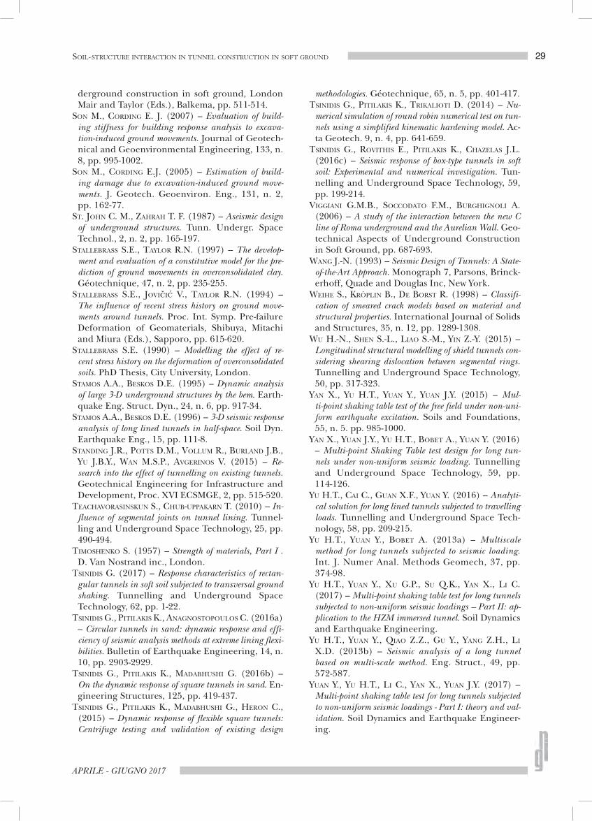
29
APRILE - GIUGNO 2017
SOIL-STRUCTURE INTERACTION IN TUNNEL CONSTRUCTION IN SOFT GROUND
derground construction in soft ground, London Mair and Taylor (Eds.), Balkema, pp. 511-514.
SON M., CORDING E. J. (2007) – Evaluation of build-ing stiffness for building response analysis to excava-tion-induced ground movements. Journal of Geotech-nical and Geoenvironmental Engineering, 133, n. 8, pp. 995-1002.
SON M., CORDING E.J. (2005) – Estimation of build-ing damage due to excavation-induced ground move-ments. J. Geotech. Geoenviron. Eng., 131, n. 2, pp. 162-77.
ST. JOHN C. M., ZAHRAH T. F. (1987) – Aseismic design of underground structures. Tunn. Undergr. Space Technol., 2, n. 2, pp. 165-197.
STALLEBRASS S.E., TAYLOR R.N. (1997) – The develop-ment and evaluation of a constitutive model for the pre-diction of ground movements in overconsolidated clay. Géotechnique, 47, n. 2, pp. 235-255.
STALLEBRASS S.E., JOVIČIĆ V., TAYLOR R.N. (1994) – The influence of recent stress history on ground move-ments around tunnels. Proc. Int. Symp. Pre-failure Deformation of Geomaterials, Shibuya, Mitachi and Miura (Eds.), Sapporo, pp. 615-620.
STALLEBRASS S.E. (1990) – Modelling the effect of re-cent stress history on the deformation of overconsolidated soils. PhD Thesis, City University, London.
STAMOS A.A., BESKOS D.E. (1995) – Dynamic analysis of large 3-D underground structures by the bem. Earth-quake Eng. Struct. Dyn., 24, n. 6, pp . 917-34.
STAMOS A.A., BESKOS D.E. (1996) – 3-D seismic response analysis of long lined tunnels in half-space. Soil Dyn. Earthquake Eng., 15, pp. 111-8.
STANDING J.R., POTTS D.M., VOLLUM R., BURLAND J.B., YU J.B.Y., WAN M.S.P., AVGERINOS V. (2015) – Re-search into the effect of tunnelling on existing tunnels. Geotechnical Engineering for Infrastructure and Development, Proc. XVI ECSMGE, 2, pp. 515-520.
TEACHAVORASINSKUN S., CHUB-UPPAKARN T. (2010) – In-fluence of segmental joints on tunne l lining. Tunnel-ling and Underground Space Technology, 25, pp. 490-494.
TIMOSHENKO S. (1957) – Strength of materials, Part I . D. Van Nostrand inc., London.
TSINIDIS G. (2017) – Response characteristics of rectan-gular tunnels in soft soil subjected to transversal ground shaking. Tunnelling and Underground Space Technology, 62, pp. 1-22.
TSINIDIS G., PITILAKIS K., ANAGNOSTOPOULOS C. (2016a) – Circular tunnels in sand: dynamic response and effi-ciency of seismic analysis methods at extreme lining flexi-bilities. Bulletin of Earthquake Engineering, 14, n. 10, pp. 2903-2929.
TSINIDIS G., PITILAKIS K., MADABHUSHI G. (2016b) – On the dynamic response of square tunnels in sand. En-gineering Structures, 125, pp. 419-437.
TSINIDIS G., PITILAKIS K., MADABHUSHI G., HERON C., (2015) – Dynamic response of flexible square tunnels: Centrifuge testing and validation of existing design
methodologies. Géotechnique, 65, n. 5, pp. 401-417. TSINIDIS G., PITILAKIS K., TRIKALIOTI D. (2014) – Nu-
merical simulation of round robin numerical test on tun-nels using a simplified kinematic hardening model. Ac-ta Geotech. 9, n. 4, pp. 641-659.
TSINIDIS G., ROVITHIS E., PITILAKIS K., CHAZELAS J.L. (2016c) – Seismic response of box-type tunnels in soft soil: Experimental and numerical investigation. Tun-nelling and Underground Space Technology, 59, pp. 199-214.
VIGGIANI G.M.B., SOCCODATO F.M., BURGHIGNOLI A. (2006) – A study of the interaction between the new C line of Roma underground and the Aurelian Wall. Geo-technical Aspects of Underground Construction in Soft Ground, pp. 687-693.
WANG J.-N. (1993) – Seismic Design of Tunnels: A State-of-the-Art Approach. Monograph 7, Parsons, Brinck-erhoff, Quade and Douglas Inc, New York.
WEIHE S., KRÖPLIN B., DE BORST R. (1998) – Classifi-cation of smeared crack models based on material and structural properties. International Journal of Solids and Structures, 35, n. 12, pp. 1289-1308.
WU H.-N., SHEN S.-L., LIAO S.-M., YIN Z.-Y. (2015) – Longitudinal structural modelling of shield tunnels con-sidering shearing dislocation between segmental rings. Tunnelling and Underground Space Technology, 50, pp. 317-323.
YAN X., YU H.T., YUAN Y., YUAN J.Y. (2015) – Mul-ti-point shaking table test of the free field under non-uni-form earthquake excitation. Soils and Foundations, 55, n. 5. pp. 985-1000.
YAN X., YUAN J.Y., YU H.T., BOBET A., YUAN Y. (2016) – Multi-point Shaking Table test design for long tun-nels under non-uniform seismic loading. Tunnelling and Underground Space Technology, 59, pp. 114-126.
YU H.T., CAI C., GUAN X.F., YUAN Y. (2016) – Analyti-cal solution for long lined tunnels subjected to travelling loads. Tunnelling and Underground Space Tech-nology, 58, pp. 209-215.
YU H.T., YUAN Y., BOBET A. (2013a) – Multiscale method for long tunnels subjected to seismic loading. Int. J. Numer Anal. Methods Geomech, 37, pp. 374-98.
YU H.T., YUAN Y., XU G.P., SU Q.K., YAN X., LI C. (2017) – Multi-point shaking table test for long tunnels subjected to non-uniform seismic loadings – Part II: ap-plication to the HZM immersed tunnel. Soil Dynamics and Earthquake Engineering.
YU H.T., YUAN Y., QIAO Z.Z., GU Y., YANG Z.H., LI X.D. (2013b) – Seismic analysis of a long tunnel based on multi-scale method. Eng. Struct., 49, pp. 572-587.
YUAN Y., YU H.T., LI C., YAN X., YUAN J.Y. (2017) – Multi-point shaking table test for long tunnels subjected to non-uniform seismic loadings - Part I: theory and val-idation. Soil Dynamics and Earthquake Engineer-ing.

RIVISTA ITALIANA DI GEOTECNICA
30 BILOTTA
Problemi d’interazione tra terreno e strutture: costruzioni in sotterraneo
Sommario
La progettazione di gallerie è un esercizio per sua natura multidisciplinare poiché coinvolge diverse professionalità e proprio per questo può aprire nuove opportunità nella ricerca innovativa. Tra le diverse discipline interessate, l’ingegneria strutturale e l’ingegneria geotecnica sono forse quelle che mostrano di avere maggiori similitudini rispetto alle altre.
Si può quindi ragionevolmente prevedere un’integrazione interdisciplinare tra le due, al fine di metterne in stretta relazione gli aspetti interdipendenti. Ne consegue che è proprio nella soluzione dei problemi di interazione tra terreno e struttura che va indirizzato tale sforzo interdisciplinare. Il lavoro intende fotografare le attuali tendenze della ricerca sull’interazione terreno-struttura nel campo della costruzione di gallerie, a diverse scale: partendo dal comportamento dell’elemento di volume, passando a problemi al finito di interazione tra la galleria e il terreno circostante e arrivando, a scala più ampia, all’interazione tra le infrastrutture sotterranee e l’ambiente urbano.