solenoid actuated diesel engine air shutdownvalves - amot · (engine run) position and manual...
TRANSCRIPT

by AMOT
DS-SVX-SolenoidActuatedValve-CE228-0712-rev1
Models SVX-380, SVX-381, SVX-384, SVX-385SVX-390, SVX-391, SVX-394, SVX-395SVX-580, SVX-581, SVX-584, SVX-585SVX-590, SVX-591, SVX-594, SVX-595SVX-880, SVX-881, SVX-884, SVX-885SVX-890, SVX-891, SVX-894, SVX-895
Energized to Stop Types
Solenoid Actuated Diesel Engine Air ShutdownValves
www.chalwyn.com
DS-SVX-SolenoidActuatedValves-CE228-0712-rev1
Solenoid Acuated Shutdown Valves - SVX
page 2
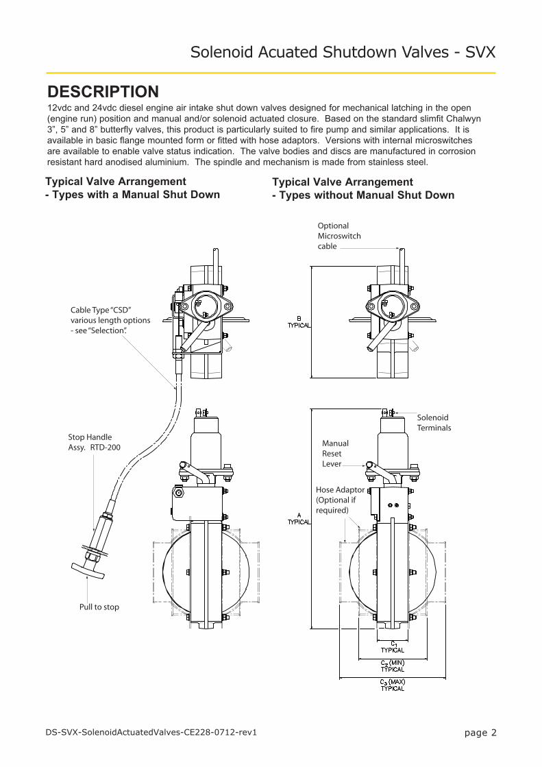
12vdc and 24vdc diesel engine air intake shut down valves designed for mechanical latching in the open (engine run) position and manual and/or solenoid actuated closure. Based on the standard slimfit Chalwyn 3”, 5” and 8” butterfly valves, this product is particularly suited to fire pump and similar applications. It is available in basic flange mounted form or fitted with hose adaptors. Versions with internal microswitches are available to enable valve status indication. The valve bodies and discs are manufactured in corrosion resistant hard anodised aluminium. The spindle and mechanism is made from stainless steel.
DESCRIPTION
Typical Valve Arrangement- Types without Manual Shut Down
Typical Valve Arrangement- Types with a Manual Shut Down
Cable Type “CSD” various length options- see “Selection”.
Stop Handle Assy. RTD-200
Pull to stop
OptionalMicroswitchcable
SolenoidTerminals
Manual ResetLever
Hose Adaptor (Optional if required)

DS-SVX-SolenoidActuatedValves-CE228-0712-rev1
Solenoid Acuated Shutdown Valves - SVX
page 3
Valve TypeWith
MicroswitchWithout
Microswitch
SVX-380SVX-390SVX-580SVX-590SVX-880SVX-890
SVX-381SVX-391SVX-581SVX-591SVX-881SVX-891
122412241224
76 (3”)76 (3”)
127 (5”)127 (5”)203 (8”)203 (8”)
270270326326
424.5424.5
111.5111.5167167257257
37.537.545.545.556.056.0
82.5 to 112.5 82.5 to 112.5 102 to 157.5 102 to 157.5136.5 to 185.5136.5 to 185.5
Voltage A C1Nominal Bore
Dia.
WithMicroswitch
WithoutMicroswitch
SVX-384SVX-394SVX-584SVX-594SVX-884SVX-894
SVX-385SVX-395SVX-585SVX-595SVX-885SVX-895
122412241224
76 (3”)76 (3”)
127 (5”)127 (5”)203 (8”)203 (8”)
270270326326
424.5424.5
111.5111.5167167257257
37.537.545.545.556.056.0
82.5 to 112.5 82.5 to 112.5 102 to 157.5 102 to 157.5136.5 to 185.5136.5 to 185.5
Voltage B C2 (min & max)
Important NotesThese Chalwyn valves are intended for emergency use. ALWAYS retain an engine fuel stop system for routine shut down.
Maximum temperature of the engine intake air at the SVX valve not to exceed 150°C. [See also “Installation (Mechanical)” - page 4]
Main Dimensions (mm) and Features- Valves with Manual Shut Down
Valve Type

DS-SVX-SolenoidActuatedValves-CE228-0712-rev1
Solenoid Acuated Shutdown Valves - SVX
page 4
SELECTIONThis valve family is suited to applications where a combination of manual latching to the open (engine run) condition with an electrical signal to close is specified. A manual stop option can additionally be specified.
Determine the size and position of the SVX valve to be installed. Within the various constraints imposed by the application, the valve should be as generously sized as possible. Check that the valve can be installed such that the electrical cable can be routed away without risk of damage. Furthermore, if the manual shut down option is also to be specified, determine the route of the shut down cable and then select the required length from the table across. Note that other cable lengths may be available on request.
Determine voltage of valve required. If a valve sta-tus indicator is specified, select a valve with an internal microswitch.
Chalwyn ‘X’ valves are designed for flange mounting. Alternatively these valves can be supplied with fit-ted hose adaptors selected from the table below.
Hose Adaptor Options
203mm (8”) Bore Valves Adaptor To Suit Hose Bore Part Number mm (inches) HAX-807 178 (7) HAX-808 203 (8)
127mm (5”) Bore Valves Adaptor To Suit Hose Bore Part Number mm (inches) HAX-501 89 (3 1/2) HAX-503 95 (3 3/4) HAX-505 102 (4) HAX-507 108 (4 1/4) HAX-509 114 (4 1/2) HAX-511 121 (4 3/4) HAX-513 127 (5) HAX-518 140 (5 1/2) HAX-523 152 (6)
76mm (3”) Bore Valves Adaptor To Suit Hose Bore Part Number mm (inches) HAX-320 38 ( 11/2) HAX-322 44.5 (13/4) HAX-301 51 (2) HAX-303 57 (2 1/4) HAX-304 60 (2 3/8) HAX-305 63.5 (2 1/2) HAX-306 67 (2 5/8) HAX-307 70 (2 3/4) HAX-309 76 (3) HAX-312 82.5 (31/4 ) HAX-314 89 (3 1/2) HAX-319 102 (4)
Cable Part No. Length (meters)
CSD-100 1.0
CSD-150 1.5
CSD-200 2.0
CSD-300 3.0
Selection Chart - Mechanical Stop Cables.

DS-SVX-SolenoidActuatedValves-CE228-0712-rev1
Solenoid Acuated Shutdown Valves - SVX
page 5
1. Valves which include the manual shut down option are supplied complete with the manual stop cable and ‘T’ handle fitted and adjusted. Do not separate the cable from handle or valve (see paragraph 9).
2. In the case of a naturally aspirated engine, the Chalwyn SVX shut down valve should gener-ally be fitted as close to the engine air intake manifold as possible. If an air intake flame trap is also fitted, the SVX valve must be installed upstream (air cleaner side) of the flame trap.
3. To avoid excessively high intake air temperature at the SVX valve when fitted to a turbocharged engine, it may be necessary to fit the valve either upstream of the turbocharger or down-stream of the intercooler (if fitted). Again, if an air intake flametrap is also fitted, the valve must be installed upstream of the flametrap.
4. Where more than one SVX valve is installed on an engine, as in the case of an engine with multiple intake pipes, the shut down valve control system must be arranged to ensure all valves close simultaneously.
5. This valve may be installed either horizontally or vertically.
6. If hose adaptors are used, the mating hose should be of a reinforced type, provide adequate support for the valve and prevent exces-sive vibration. If necessary, additional support brackets mounted from the engine should be considered.
7. Particular care must be taken to ensure the integrity of the intake pipework between the Chalwyn valve and intake manifold. Ideally metal pipework should be used and any gaps kept as short as possible, (taking into account any relative movement,) and closed by reinforced hose.
8. Any engine crankcase breather connections into the intake system between the SVX valve and engine, or any internal crankcase breather arrangement venting directly into the engine intake ports must be sealed and replaced by an external breather system venting either to atmosphere or to the intake system upstream of the shut down valve. External breather system kits for various engine types are available from Chalwyn.
INSTALLATION (MECHANICAL)
9. Valves fitted with manual shut down handle assembly RTD-200. Prepare a Ø10mm (3/8”) hole in the panel/bracket to which the stop control is to be mounted. Release the handle locknut. Remove the handle, handle lock nut and mounting nut. Offer up the RTD-200 body to the back face of the panel/bracket allowing the internal rod of the RTD-200 to project through the prepared hole. Refit the mounting nut and fully tighten. Refit handle locknut winding as far as possible onto the threaded rod. Refit handle winding hard down onto the locknut and then tightening locknut onto the handle. Note during this operation the handle and locknut will need to be held out against the valve spring return load.
‘T’ HANDLE
‘T’ HANDLE LOCK NUT
MOUNTINGNUT
PANEL OR MOUNTING
BRACKET
BODY
NOTE: If body is separated from cable, ensure that whenre-assembling the chamfered end of the body is towards cable.
STOP CABLE
Handle Assembly Type RTD-200

DS-SVX-SolenoidActuatedValves-CE228-0712-rev1
Solenoid Acuated Shutdown Valves - SVX
page 6
The actuating solenoid is a two wire type with internal switching from pull to hold current. On supply of power, the full pull current is drawn for less than 1 second before switching to the hold current. Once the valve has closed the power supply to the solenoid can be removed at any time. The valve will not re-open until manually reset.
Electrical Data for the Solenoid
Valve ModelSVX-380 SVX-381 SVX-384 SVX-385 SVX-580 SVX-581 SVX-584 SVX-585 SVX-880 SVX-881 SVX-884 SVX-885
Supply voltage
Pull current
Hold current
Max. length for supply cable (2.5mm2)
Max. length for supply cable (4.0mm2)
12 vdc
46 amps
1.1 amps
2.7m
4.2m
24 vdc
25 amps
0.5 amps
10m
16m
Valve models SVX-380, SVX-384, SVX-390, SVX-394, SVX-580, SVX-584, SVX-590, SVX-594, SVX-880, SVX-884, SVX-890 and SVX-894 have a built-in microswitch. This enables an indication of the valve open/close status. The microswitch connections are made as follows:- Brown : Supply - common Blue : Makes circuit when valve is closed Black : Makes circuit when valve is open. (Was yellow/green on early models.)Maximum rating of microswitch at 12 or 24 volts = 2 amp
INSTALLATION (Electrical)
SVX-390 SVX-391 SVX-394 SVX-395 SVX-590 SVX-591 SVX-594 SVX-595 SVX-890 SVX-891 SVX-894 SVX-895

DS-SVX-SolenoidActuatedValves-CE228-0712-rev1
Solenoid Acuated Shutdown Valves - SVX
page 7
MAINTENANCEWEEKLY:
MONTHLY:
Visually check the valve, solenoid and cables for damage or deterioration. Withdraw from service if significant damage or deterioration is observed.
1. Check that the fasteners locating the shut down valve and any associated intake system or support bracket fasteners are securely tightened.
2. Check that any flexible hoses in the engine intake between the SVX valve and engine are free from damage and suitable for further service.
3. Run engine, preferably at low idle. Apply the appropriate voltage to the solenoid to close the intake shut down valve. The engine should stop within a few seconds. If not, check there are no leaks in the engine air intake system between the SVX valve and engine. If this does not resolve the problem remove the SVX valve to return to Chalwyn for investigation.
4. If the manual stop option is fitted to the valve, repeat ‘3’ above but using the manual intake valve stop. Again the engine should stop within a few seconds.
Prior to starting the engine, the SVX valve must be latched open by rotating the manual reset lever clock-wise as far as possible. Additionally, if the manual stop option is fitted, ensure that the stop handle is pushed inwards to the run (valve open) condition.
Once latched, the reset lever will remain in the open position until either released by the action of the solenoid to close the valve or, where fitted, by the operation of the valve’s manual stop control.
Normal engine shut down via the fuel stop will not result in the Chalwyn valve closing.
OPERATION

by AMOT
Americas
AMOT - USATel: +1 281 940 1800 Fax: +1 713 559 [email protected] Roda Deaco by AMOT - CanadaTel: +1 780 465 4429 Fax: +1 780 469 [email protected]
Europe, Middle East and Africa
AMOT - UKTel: +44 (0)1284 715739 Fax: +44 (0)1284 [email protected]
AMOT - GermanyTel: +49 (0)40 8537 1298Fax: +49 (0)40 8537 [email protected]
AMOT - RussiaTel: +7 495 617 12 96Fax: +7 495 913 97 [email protected]
Asia Pacific
AMOT - ChinaTel: +86 (0)21 6279 7700 Fax: +86 (0)21 5237 [email protected]
AMOT - SingaporeTel: +65 6408 6265 Fax: +65 6408 [email protected]
DS-S
VX-S
ole
noid
Act
uat
edVal
ves-
CE228-0
712-r
ev1
www.chalwyn.com