sonosite ultrasound system user guide · • the left side of the system is to your left as yo u...
TRANSCRIPT

SonoSiteUltrasound System User Guide


SonoSiteUltrasound SystemUser Guide

ii
Manufactured bySonoSite, Inc.21919 30th Drive SEBothell, WA 98021USAT: 1-888-482-9449 or 1-425-951-1200F: 1-425-951-1201
SonoSite LtdAlexander House40A Wilbury WayHitchinHerts SG4 0APUKT: +44-1462-444800F: +44-1462-444801
SiteCharge, SitePack, SiteStand, and SonoHeart are registered trademarks or trademarks of SonoSite, Inc.
Non-SonoSite product names may be trademarks or registered trademarks of their respective owners.
Protected by U.S. patents: 5722412, 5817024, 5893363, 6135961, 6364839, 6371918, 6383139, 6416475, 6447451, 6471651, 6648826, 6569101, 6604630, 6962566, D456509, D461895. Patents pending.
P02614-03 05/2007Copyright 2007 by SonoSite, Inc.All rights reserved. Printed in the USA.
Caution: Federal (United States) law restricts this device to sale by or on the order of a physician.

Contents
Chapter 1: IntroductionAbout the User Guide ...............................................................................1Conventions ...............................................................................................1Symbols and Terms ...................................................................................1Upgrades and User Guide Updates .......................................................1Customer Comments ................................................................................1About the System ......................................................................................2
Conventions Used on System ..........................................................2About the System Software ..............................................................5Software Licensing ............................................................................5
Chapter 2: Preparing the SystemConnecting and Removing Transducers ...............................................7Turning the System On or Off .................................................................8Installing and Removing Battery ............................................................9Using AC Power ......................................................................................10Upgrading the System Software ...........................................................10Obtaining a License Key ........................................................................11Installing a License Key ..........................................................................12Checking and Charging the Battery .....................................................14Using the SiteCharge® Dual Battery Charger .....................................16Using System Setup ................................................................................17Using the SiteStand® Mobile Docking Station ...................................23Using Software ........................................................................................23
SiteLink Image Manager ................................................................23IrfanView Software .........................................................................24
Chapter 3: ImagingPreparing for the Exam ..........................................................................25
Transducer, Exam Type, and Imaging Mode ..............................262D Imaging ...............................................................................................28M-mode Imaging .....................................................................................30Color Power Doppler (CPD) or Directional Color Power Doppler (DCPD) Imaging ..........................32Pulsed Wave (PW) and Continuous Wave (CW) Doppler Imaging 33ECG Monitoring ......................................................................................36Annotating Images ..................................................................................37Needle Guidance .....................................................................................40Printing Images .......................................................................................40Saving and Reviewing Images ..............................................................41Recording Images ....................................................................................42After the Exam .........................................................................................42
iii
iv
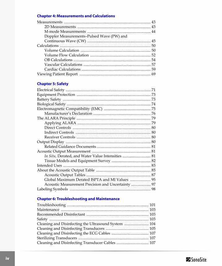
Chapter 4: Measurements and CalculationsMeasurements ......................................................................................... 43
2D Measurements ........................................................................... 43M-mode Measurements ................................................................. 44Doppler Measurements–Pulsed Wave (PW) and Continuous Wave (CW) ................................................................. 45
Calculations ............................................................................................. 50Volume Calculation ........................................................................ 50Volume Flow Calculation .............................................................. 52OB Calculations ............................................................................... 54Vascular Calculations ..................................................................... 57Cardiac Calculations ....................................................................... 59
Viewing Patient Report ......................................................................... 69
Chapter 5: SafetyElectrical Safety ....................................................................................... 71Equipment Protection ............................................................................ 73Battery Safety .......................................................................................... 73Biological Safety ...................................................................................... 74Electromagnetic Compatibility (EMC) ................................................ 75
Manufacturer’s Declaration ........................................................... 76The ALARA Principle ............................................................................ 79
Applying ALARA ........................................................................... 79Direct Controls ................................................................................ 80Indirect Controls ............................................................................. 80Receiver Controls ............................................................................ 80
Output Display ....................................................................................... 80Related Guidance Documents ....................................................... 81
Acoustic Output Measurement ............................................................ 81In Situ, Derated, and Water Value Intensities ............................. 81Tissue Models and Equipment Survey ........................................ 82
Intended Uses .......................................................................................... 83About the Acoustic Output Table ........................................................ 85
Acoustic Output Tables .................................................................. 87Global Maximum Derated ISPTA and MI Values ..................... 95Acoustic Measurement Precision and Uncertainty .................... 97
Labeling Symbols ................................................................................... 98
Chapter 6: Troubleshooting and MaintenanceTroubleshooting .................................................................................... 101Maintenance .......................................................................................... 103Recommended Disinfectant ................................................................ 103Safety ...................................................................................................... 103Cleaning and Disinfecting the Ultrasound System ......................... 104Cleaning and Disinfecting Transducers ............................................ 105Cleaning and Disinfecting the ECG Cables ...................................... 107Sterilizing Transducers ........................................................................ 107Cleaning and Disinfecting Transducer Cables ................................. 107

Chapter 7: ReferencesMeasurement Accuracy ........................................................................123
Display Size ....................................................................................123Caliper Placement ..........................................................................1232D Measurements and Calculations ...........................................123Sources of Measurement Errors ..................................................125Acquisition Error ...........................................................................125Algorithmic Error ..........................................................................125Terminology and Measurement Publications ...........................125
Cardiac References ................................................................................126Obstetrical References ..........................................................................129General References ................................................................................132
Chapter 8: SpecificationsPhysical Dimensions .............................................................................135Monitor ...................................................................................................135Transducers ............................................................................................135Imaging Modes ......................................................................................135Applications ...........................................................................................136Display Elements ...................................................................................136Ultrasound System Controls ...............................................................137Measurements and Calculations .........................................................137
2D .....................................................................................................137M-mode ...........................................................................................137PW and CW Doppler Mode .........................................................137Volume ............................................................................................137Volume Flow ..................................................................................138Cardiac Calculations .....................................................................138Obstetrical Calculations ................................................................139Fetal Tables .....................................................................................140Vascular ..........................................................................................140
Image Storage ........................................................................................140Accessories .............................................................................................141Peripherals .............................................................................................142
Medical Grade ................................................................................142Non-medical Grade (Commercial) .............................................142
Temperature, Pressure, and Humidity Limits ..................................142System Operating ..........................................................................142System Shipping/Storage ............................................................142Battery Operating ..........................................................................142Battery Shipping/Storage ............................................................142Transducers Operating .................................................................142Transducers Shipping/Storage ...................................................143
v

vi
Electrical ................................................................................................. 143Battery .................................................................................................... 143Electromechanical Safety Standards .................................................. 143EMC Standards Classification ............................................................ 144Airborne Equipment Standards (without ECG Cable attached) ... 144ECG Standard ....................................................................................... 144
Chapter 9: GlossarySymbols .................................................................................................. 145
Icons ................................................................................................ 146Terms .............................................................................................. 150
Acronyms ............................................................................................... 160
Index ....................................................................................................... 165

Introduction
Chapter 1: Introduction
Please read the information in this user guide before using the ultrasound system. It applies to the ultrasound system, transducers, accessories, and peripherals.
About the User GuideThis user guide is a reference for using the ultrasound system. It is designed for a reader familiar with ultrasound techniques; it does not provide training in sonography or clinical practices. Before using the system, you must have ultrasound training.The user guide covers the preparation, use, and maintenance of the ultrasound system, transducers, and accessories. See the manufacturers’ instructions for specific information about peripherals.
ConventionsThese conventions are used in this user guide:• A Warning describes precautions necessary to prevent injury or loss of life.• A Caution describes precautions necessary to protect the products.• Numbered steps in the operating instructions must be performed in a specific order.• Bulleted lists present information in list format, but they do not imply a sequence.• The left side of the system is to your left as you face the system. The system handle is at the top
of the system, the battery compartment is at the bottom of the system.
Symbols and TermsSymbols and terms used on the system, are explained in, Chapter 5, “Safety”and/or Chapter 9, “Glossary.”
Upgrades and User Guide UpdatesSonoSite may offer software upgrades, new features, and improvements to the system performance. User guide updates accompany the upgrade software and provide detailed information on the enhancements.
Customer CommentsQuestions and comments are encouraged. SonoSite is interested in your feedback regarding the system and the user guide. Please call SonoSite at 1-888-482-9449. If you are outside the USA, call the nearest SonoSite representative. You can also send electronic mail (e-mail) to SonoSite at the following address: [email protected].
Chapter 1: Introduction 1

2
Intr
oduc
tion
About the SystemThe SonoSite system has various configurations and features. All are described in this manual but not every option may apply to your system. System features are dependent on your system configuration, transducer and exam type.The SonoSite system is a portable, software-controlled, ultrasound system. It has an all-digital architecture. It is used to acquire and display high-resolution, real-time, 2D, color power Doppler (CPD), directional color power Doppler (DCPD), Tissue Harmonic Imaging (THI), M-mode, pulsed wave (PW) Doppler, and continuous wave (CW) Doppler ultrasound images. The system has electrocardiography (ECG), cine review, image zoom, labeling, biopsy, measurements and calculations, serial connection for image transfer, image storage and review, printing and recording with the capability of archiving Doppler with audio output to a videotape. The system setup also has a selection to support optical character recognition (OCR) of the English character set for time, date, patient name, and patient identification. The OCR screen characters are optimized for use with the ALI NewPORT DICOM image capture station peripheral available from ALI. For more information about the ALI NewPORT 2.1, see the ALI NewPORT 2.1 Image Capture Station User’s Guide.Currently, the system supports the following transducers:• C8/8-5 MHz 8-mm microcurved array• C11/7-4 MHz 11-mm microcurved array• C15/4-2 MHz 15-mm microcurved array• C60/5-2 MHz 60-mm curved array• HST/10-5 MHz 25-mm linear array• ICT/7-4 MHz 11-mm intracavitary array• L25/10-5 MHz 25 mm linear array• L38/10-5 MHz 38-mm linear arraySystem accessories include a SiteStand® mobile docking station, flat panel display, VCR bracket for SiteStand, SiteCharge® dual battery charger, a power adapter, a battery, ECG cable, video and printer cables, audio cable, SiteLink image manager software, Basic Stand, CRT Stand, ScanPack quick access carrier, Grab and Go Carrying Case, and SitePack® protective carry pack.System peripherals include medical grade (conforming to the requirements of EN60601-1) and non-medical (commercial) grade products. System medical grade peripherals include an external color monitor, video printers, and VCR. System non-medical grade peripherals include a digital video recorder, a battery charger, a lithium-ion battery, printer, and a handheld monitor. Use of peripherals is covered in the manufacturers’ instructions, which accompany each peripheral. System setup instructions for the use of peripherals are covered in “Using System Setup” on page 17.
Conventions Used on SystemThe software that runs the system uses graphic display elements similar to those used in many personal computers. System symbols and terms are explained in the “Glossary”.If a menu item or icon is selectable, then the menu item or icon is light gray. If a menu item or icon is not selectable, then the menu item or icon is dark gray. The active menu item or icon is green.
Chapter 1: Introduction

Introduction
The following figure and table describe the system controls.
Rear view3
2
1
4
5
678
10
9
11
12
13
1415
1617
Number Feature
1 Power switch, located on the rear of the system handle
2 Near, affects gain of shallow echoes
3 Far, affects gain of deeper echoes
4 Gain, affects overall gain
5 Menu select controls
6 Menu, Depth, and Zoom
7 Trackball
8 Patient
9 Function key
10 Battery charge indicators
Chapter 1: Introduction 3

4
Intr
oduc
tion
The following figure shows the display and the layout of the screen:
11 LCD (liquid crystal display) brightness control
12 LCD contrast control
13 LCD
14 Print/VCR or Print key
15 Cine Arrow keys and Freeze key
16 Mode controls
17 Battery release
Number Feature
Exam typeMenu select
Patient name
Message line 1(calc results)
Message line 2 (calc measurements)
Date Time
Patient ID
Scale
Text Annotation
Picto
ECG trace
Measurements/menu labels
Transducer
Reference image/mode
Optimization/angle correct
Menu icons
Menu labels
Depth
Image memoryBattery/AC plug
Working/print/recordMI/TI
Scale
Chapter 1: Introduction

Introduction
About the System SoftwareYour SonoSite system contains software that controls its operation. From time to time, SonoSite may provide new software for use with your system. This software is provided using a software update module or a transducer. This software is either required or optional. A single module or transducer can be used to update one or more systems.When the new software is required, you must install it if you wish to use the new software features (e.g., new transducer). If you choose not to install it, you must remove the transducer and replace it with one that is compatible with the software that is currently installed in your system.When the software is optional, you can either install it or choose to use your existing software. If you choose not to install the software, the system will prompt you again whenever the system is started, and whenever the transducer is disconnected and then reconnected to the system.See “Upgrading the System Software” on page 10 for more information on software upgrades.
Software LicensingUse of the software that you receive from SonoSite is controlled by a license key. A license key is a number sequence containing exactly 12 decimal digits.License keys are obtained from SonoSite or from its authorized representatives. You must obtain one key for each system that will use the new software. See “Obtaining a License Key” on page 11 for information on obtaining a license key.Software that you receive from SonoSite may be installed and will operate for a short period of time without requiring a valid license key. We refer to this period of time as the “grace period.” The grace period is variable.When you first install your software, your SonoSite system will prompt you for a license key. If you have not yet obtained a valid license key, you can elect to use the software as long as the grace period time has not been fully consumed. We refer to this mode of operation as “running in the grace period.”When a system is running in the grace period, all system functions are available. As you use the system, the grace period is slowly consumed. When the grace period has expired, the system will not be usable until a valid license key has been entered. Grace period time is not consumed while the system is powered off or when it is in “sleep” mode. Whenever a system is running in the grace period, the grace period time remaining is available on the license update screen. For information on displaying this screen, see “Installing a License Key” on page 12“.
Caution: When the grace period expires, all system functions except for licensing will become unavailable until a valid license key is entered into the system.
Chapter 1: Introduction 5

6
Intr
oduc
tion
Chapter 1: Introduction

Preparing System
Chapter 2: Preparing the System
Connecting and Removing TransducersNote: Only one transducer can be connected to the system at a time.
Warning: The transducer connector can become hot during operation. This is normal. Operate the system in the SiteStand mobile docking station or on a flat, hard surface to allow air flow past the connector.
Caution: The electrical contacts inside the system transducer connector may be damaged by foreign material or by rough handling. Do not touch the electrical contacts. Keep foreign material out of the connector. Keep a transducer connected to the system whenever possible.
Transducer connectorTransducer connector latch
Chapter 2: Preparing the System 7

8
Prep
arin
g Sy
stem
To connect the transducer:1 On the transducer connector, pull the latch up and rotate it clockwise until it snaps to a stop.
The latch should be easy to move. Do not force the latch.2 Align the transducer connector with the connector on the rear of the system and insert it by
pushing the transducer connector into the system connector. The transducer connector should be easy to insert. Do not force the transducer connector.
3 Turn the latch counterclockwise until it snaps to a stop.4 Press the latch down until it snaps into place, securing the transducer connector to the system.
To remove the transducer:1 On the transducer connector, pull the latch up and rotate it clockwise until it snaps to a stop.2 Carefully pull the transducer connector away from the system.
Turning the System On or OffWhen turning power on or off, you must push and hold the Power switch for approximately one second before the system responds. This feature prevents battery discharge, resulting from accidentally turning the system on. It also prevents accidentally turning the system off during an exam.The first time you turn on the system, set the date and time. See “To set the date and time:” on page 57.
To turn power on/off:1 Locate the Power switch on the back of the left side of the system handle. See the System
Controls photograph in Chapter 1 on page 1.2 Press and hold the Power switch until the system beeps (approximately one second).3 Release the Power switch.
To wake up the system:The system has a sleep delay, which is activated through the sleep delay system setup. When the battery charge indicators are blinking, but the other system lighting is off, press any key to wake up the system.
Caution: Do not use the system if an error message appears on the image display. Note the error code. Call SonoSite or your local representative. When an error code occurs, turn off the system by pressing and holding the power switch until the system powers down.
Chapter 2: Preparing the System

Preparing System
Installing and Removing BatteryThe battery comprises six lithium-ion cells (two sets of three connected in series) plus electronics, a temperature sensor, and the battery contacts. When in use, it is inserted into the system.
If the battery is being installed for the first time, it will need to be charged. See “Checking and Charging the Battery” on page 14. Make sure to remove the protective tape from the battery contacts before charging the battery.
To install the battery:1 Locate the battery compartment at the bottom of the system.2 To install a new battery (label side up) into the battery compartment, push it into
the compartment until both sides click into place. (Do not force the battery into the compartment, check the battery orientation if the battery is difficult to install.) Ensure that both sides of the battery are fully connected and that the battery release button is not pressed.
To remove the battery:1 Turn off the system.2 Locate the battery compartment at the bottom of the system.
3 To release the battery, press the battery release button (lower, right side) on the system.
Warning: If you are holding the system, when you remove the battery, place your hand beneath the battery. If it falls to the floor, it could be damaged, or cause personal injury.
Warning: If you are holding the system, when you remove the battery, place your hand beneath the battery. If it falls to the floor, it could be damaged, or cause personal injury.
Chapter 2: Preparing the System 9

10
Prep
arin
g Sy
stem
Using AC PowerThe battery charges when the system is using AC power. If the system is off and connected to AC power, a fully discharged battery will charge in about three hours.
To operate the system using AC power:1 Connect the AC line cord of the AC power adapter to a hospital-grade electrical outlet.2 Connect the DC line cord of the AC power adapter to the power connector on the system. See
arrow labeled 1 in the figure below.3 Connect the AC power adapter to the system using the upper, left connector on the left side of
the system.See Table 1, “System Connectors” on page 15 for placement of connectors.
Upgrading the System SoftwareAs described in Chapter 1, “Introduction”, on page 1, transducers that you receive from SonoSite may contain either required or optional upgrades to the system software that resides on your SonoSite system.Whenever you connect a transducer to a SonoSite system, the system communicates with the transducer to determine if it contains software that would upgrade the system.
To upgrade the system software:1 When you first connect a transducer with new software and turn the system on, the following
message is displayed:Do you want to upgrade the system software?For required upgrades:You must either perform the upgrade or replace the transducer with one that is compatible with the software currently installed on your system. Do one of the following:• Select no (disconnect transducer) to reject the system software upgrade.• Select yes (up to 20 minutes) to accept the system software upgrade and go to step 2.For optional upgrades:You may either install the new software or continue to use the existing software. SonoSite recommends that you install these optional upgrades soon after receiving them. Do one of the following:• Select no (continue) to use the system without upgrading.• Select yes (up to 20 minutes) to accept the upgrade and go to step 2.
2 When you have accepted the upgrade, the system loads the new software and displays the following message: Upgrade in progress (20 minutes total).Note: The system upgrade can take up to 20 minutes; however, many software upgrades will be completed in less time.
Caution: Initiating any upgrade of the system software erases any images stored on your system. Do not upgrade the system software until you have determined that any stored images are no longer needed.
Chapter 2: Preparing the System
Preparing System
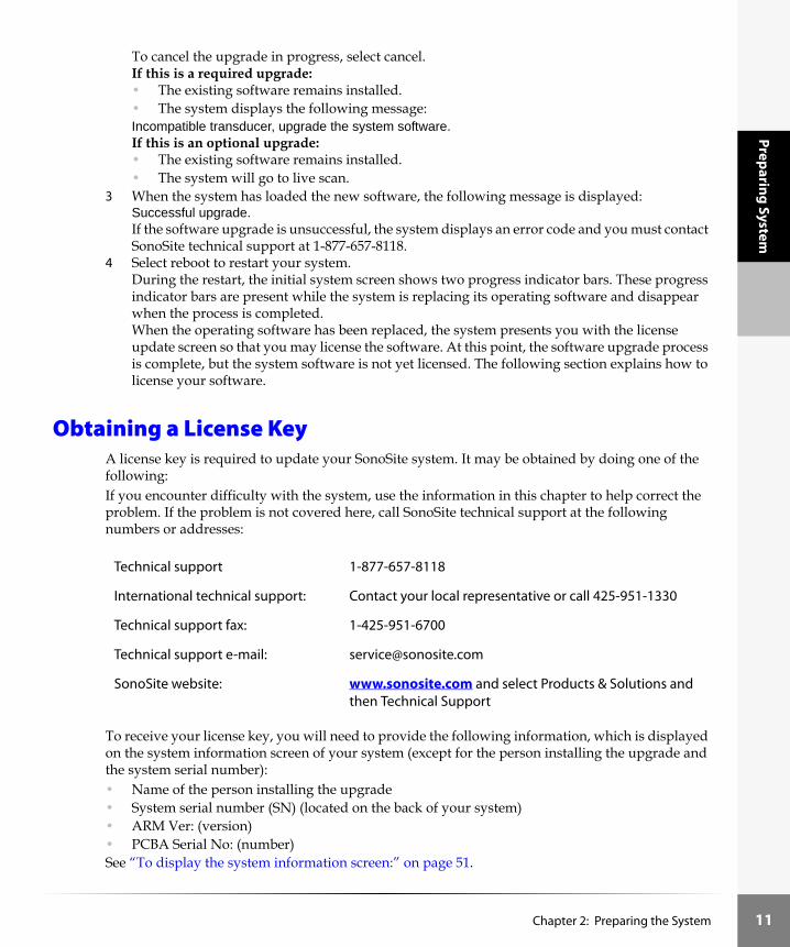
To cancel the upgrade in progress, select cancel.If this is a required upgrade:• The existing software remains installed.• The system displays the following message: Incompatible transducer, upgrade the system software.If this is an optional upgrade:• The existing software remains installed.• The system will go to live scan.
3 When the system has loaded the new software, the following message is displayed:Successful upgrade.If the software upgrade is unsuccessful, the system displays an error code and you must contact SonoSite technical support at 1-877-657-8118.
4 Select reboot to restart your system.During the restart, the initial system screen shows two progress indicator bars. These progress indicator bars are present while the system is replacing its operating software and disappear when the process is completed.When the operating software has been replaced, the system presents you with the license update screen so that you may license the software. At this point, the software upgrade process is complete, but the system software is not yet licensed. The following section explains how to license your software.
Obtaining a License KeyA license key is required to update your SonoSite system. It may be obtained by doing one of the following:If you encounter difficulty with the system, use the information in this chapter to help correct the problem. If the problem is not covered here, call SonoSite technical support at the following numbers or addresses:
To receive your license key, you will need to provide the following information, which is displayed on the system information screen of your system (except for the person installing the upgrade and the system serial number):• Name of the person installing the upgrade• System serial number (SN) (located on the back of your system)• ARM Ver: (version)• PCBA Serial No: (number)See “To display the system information screen:” on page 51.
Technical support 1-877-657-8118
International technical support: Contact your local representative or call 425-951-1330
Technical support fax: 1-425-951-6700
Technical support e-mail: [email protected]
SonoSite website: www.sonosite.com and select Products & Solutions and then Technical Support
Chapter 2: Preparing the System 11

12
Prep
arin
g Sy
stem
Installing a License KeyWhen you have obtained a license key for your software, you must enter it into the system. Once a valid license key has been entered, the system remains licensed until the next time the system software is upgraded. 1 Turn on the system.
If the software is not yet licensed, the license update screen displays.The license update screen displays the following information: the License Update number, the ARM Ver (version), the PCBA Serial No. (number), the SonoSite web site address and telephone number, the license number, the register later or done , and the grace period (time remaining) on your system.
Note: The software versions on your system may vary based on your upgrade and configuration.2 Enter your license key in the license number field.
If the license key that you entered is recognized by the system as being valid for your system and the software you installed, done appears on-screen. Select done from the on-screen menu to install the license key and license your software. If the license key that you entered is not recognized by the system, the register later button remains on the screen as long as the defined grace period has not expired.If the grace period has expired, the menu item will indicate this by showing zero hours remaining in the grace period. At this point, you must then enter a valid license key before you can use the system with this or any other transducer.
Note: If you have entered a valid license key and you cannot complete the licensing procedure, verify that the license key has been entered correctly. The license key should be exactly 12 digits (for example, 123348990552) with no other characters or punctuation. Note: If after confirming correct entry of the license key, you are still unable to license your system, call SonoSite technical support. USA/Canada customers call 1-877-657-8118. International customers call your local representative or 1-425-951-1330.If the system is on and the grace period expires, the license update screen must be displayed from the system information screen.
Chapter 2: Preparing the System

Preparing System
To display the system information screen:1 Press and release the Function key.2 Press and release I. The system information screen displays.The system information screen displays the following information: the Boot/PIC Vers (version), the ARM/DSP Vers, the PCBA Serial No (number), the Product Name, the Status, the PLD 1, 2, Vers, CPLD SH Ver, SHDB Ver (scanhead database version), and the Sh Serial No (scanhead serial number).Note: The software versions on your system may vary based on your upgrade and configuration.
To display the license update screen:1 On the system information screen, select the unlock icon (upper left corner of the screen).
The license update screen displays.2 Perform the steps in “Installing a License Key” on page 12.
Chapter 2: Preparing the System 13

14
Prep
arin
g Sy
stem
Checking and Charging the Battery
To check the battery:Note: Disconnect the system from AC power prior to checking the battery charge.Five LEDs (light-emitting diodes) on the right side of the system monitor allow you to check the battery condition. If all LEDs are lit, the battery is fully charged. A solid gray battery icon in the lower right portion of the system display indicates that a battery is properly installed. When there is approximately 10 minutes of battery life remaining, the gray battery icon will flash. At 2 minutes of battery life remaining, the battery icon turns white and the system beeps.The system will operate on a fully-charged battery for 1.5 to 4 hours, depending upon use. Ensure the battery is charged at all times to provide the longest possible battery operation. You can set the sleep delay and power delay to prolong battery life. See “Using System Setup” on page 17.When the system is not likely to be used for some time, to prevent total battery discharge, remove the battery from the system.
To charge the battery in the system:
1 Connect the AC line cord of the AC power adapter to a hospital-grade electrical outlet.2 Connect the DC line cord of the AC power adapter to the power connector on the system. See
arrow labeled 1 in the figure below.3 Charge the battery until it is fully charged.
Note: It takes about three hours to charge a battery when the system is off.4 Disconnect the system from AC power.5 Turn the system on to check the battery charge.Note: If the system power is off, the five battery LEDs will light up and then flash to indicate that the battery is charging. The LEDs will turn off once the battery is fully charged.
Caution: Charge batteries only when the ambient temperature is between 0° and 40°C (32° and 104°F).
Chapter 2: Preparing the System

Preparing System
To verify that power is connected:The system can be powered by the DC power input connector plugged directly into the system, or from the SiteStand. A power plug icon in the lower right portion of the system display indicates that DC is properly connected and that the system is operating off this power. If both the power plug icon and the battery icon are present, the battery is properly installed and the system is operating off of DC power.
21 3 4
Table 1: System Connectors
Number Feature
1 DC power input connector
2 I/O connector
3 Print/ VCR control connector for a recommended printer or VCR
4 Video out connector for a recommended VCR, printer, or external video monitor
Chapter 2: Preparing the System 15

16
Prep
arin
g Sy
stem
Using the SiteCharge® Dual Battery Charger
To use the SiteCharge dual battery charger:1 Connect the power adapter to the SiteCharge dual battery charger.2 Connect the AC line cord to a power connector.
The blue SonoSite logo on the front of the SiteCharge dual battery charger lights.3 Insert one or two batteries into the SiteCharge dual battery charger (the batteries only fit one
way).Refer to the following table for SiteCharge dual battery charger information on indicator light color, status, what it indicates, and the solution if necessary.Note: When the battery reaches full charge, both the yellow and green LEDs may be lit or may be flashing.
Table 2: Battery Status
Light Color (next to battery)
Status Indicates Solution
Yellow Lit The battery is charging. It may take up to 60 seconds for the yellow light to come on depending on the discharge state of the battery.
Chapter 2: Preparing the System

Preparing System
Using System SetupSystem setup is used to customize your system. It is available by pressing the Patient key and selecting system setup. System setup includes settings for OCR (on/off), the thermal index selection (TIS/TIB/TIC), and the pictograph (on/off), and Doppler Scale (cm/s, kHz). System setup also includes screen information settings that allow you to show or hide the following items: the optimize icon, the time, the memory icon, and the patient name. You can also set the audible beep, sleep delay, power delay, and date/time. Additionally, system setup includes the video format, printer/VCR, calcs authors, and function key assignment. You can return to imaging from any system setup function by pressing the Patient key.Perform the following procedures to become familiar with using the system setup, then use these basic operations to set the range of setups required for your uses.
Yellow Lit When lit for more than six hours, charging will be suspended.
Remove and reinsert the same battery. If the battery is not fully charged within another six hours, call SonoSite or your local representative.
Yellow Flashing The battery is not properly installed. The battery or the SiteCharge dual battery charger is defective.The ambient temperature is below 0°C (32°F) or greater than 40°C (104°F).
Re-install the battery into the SiteCharge dual battery charger. If the battery is properly installed and the yellow light still flashes, call SonoSite or your local representative.
Green Lit The battery is fully charged and is ready for use. (The SiteCharge dual battery charger can charge one or two batteries in less than four and a half hours, depending on the discharge state of the battery.)
Green Lit During an over-temperature condition, charging has been suspended.
Call SonoSite or your local representative.
Table 2: Battery Status (Continued)
Light Color (next to battery)
Status Indicates Solution
Chapter 2: Preparing the System 17

18
Prep
arin
g Sy
stem
To set the date and time:
1 Press the Patient key. A menu appears on which system setup is listed.
2 Select system setup. A menu appears on which is listed audio, power, date/time.
3 Select audio, power, date/time.4 Select date/time.
A cursor appears at the left side of the date/time display. 5 Type in the current date (year, month, day) and time in 24-hour format (hours, minutes).
If you make a mistake, you can use the Arrow keys between the Backspace and Enter keys to move the cursor.
6 Press the Patient key to return to imaging.
To set sleep delay:1 Repeat steps 1 through 3 in “To set the date and time:”2 Select sleep delay (min).3 Press sleep delay (min) again to select off, 5, or 10.4 Press the Patient key to return to imaging.
To set power delay:1 Repeat steps 1 through 3 in “To set the date and time:”2 Select power delay (min).3 Press power delay (min) again to select off, 15, or 30.4 Press the Patient key to return to imaging.
To turn on or off the audible beep:1 Repeat steps 1 through 3 in “To set the date and time:”2 Select audible beep.3 Press audible beep again to select on or off.4 Press the Patient key to return to imaging.5
To set the Thermal Index (TI):1 Press the Patient key.
A menu appears on which system setup is listed.2 Select system setup.
A menu appears on which is listed OCR, TI, picto, Doppler.3 Select OCR, TI, picto, Doppler.4 Select thermal index.
Warning: An accurate date and time are critical for accurate obstetrics calculations. Verify that the date and time are accurate before each use of the system. The system does not automatically adjust for daylight savings time changes.
Chapter 2: Preparing the System

Preparing System
5 Select thermal index until the desired TIS, TIB, or TIC is selected.6 Press the Patient key to return to imaging.
To turn on or off the OCR feature for DICOM:1 Press the Patient key.
A menu appears on which system setup is listed.2 Select system setup.
A menu appears on which is listed OCR, TI, picto, Doppler.3 Select OCR, TI, picto, Doppler.4 Select OCR.5 Select OCR again to select on or off.
The banner area of the screen turns black when OCR is turned on.6 Press the Patient key to return to imaging.
Note: You must always turn on the OCR feature prior to saving an image. Images saved without the feature turned on may not be properly identified when read by the DICOM product.
To set up a recommended printer:To use the system print controls, print, and print all images, the printer control cable must be connected to the system.
1 Connect a recommended printer to the system using the recommended print control cable and a video output cable.The connectors are on the left side of the system. There are two connections that are required: Print control connector and video out connector. See arrows labeled 3 and 4 in Table 3, “System Connectors,” on page 60.If you have questions about medical grade and non-medical grade system peripherals, refer to Chapter 1, “Introduction.”
Caution: To ensure that the patient name is read correctly by the OCR software, set up the name order choice, e.g., last name first, on the ALI NewPORT 2.1 product, refer to the ALI NewPORT 2.1 Image Capture Station User’s Guide.
To ensure that the patient name is read correctly by the OCR software, do not separate the patient’s last name by a space when there are two last names, e.g., St.Pierre, VanDekamp, or Jones-Smith.
To ensure that the patient’s name is read correctly by the OCR software, do not place a hyphen at the end of the last name, e.g., Smith Jones-.
Caution: Use only peripherals recommended by SonoSite with the system. Your system can be damaged by connecting a peripheral not recommended by SonoSite.
Chapter 2: Preparing the System 19

20
Prep
arin
g Sy
stem
2 Turn on the printer.Refer to the manufacturer’s instructions for specific printer information.
3 Press the Patient key. A menu appears on which is listed system setup.
4 Select system setup.A menu appears on which is listed video, printer/VCR, calcs, f keys.
5 Select video, printer/VCR, calcs, f keys.6 Select printer/VCR key from the on-screen menu and set it for the type of printer connected to
the system. Note: Only the printers appearing as settings are recommended for use with the system.The printer setup is ready to print.
7 Press the Patient key to return to imaging.
8 Press the Print/VCR key or use the controls on the printer to print.
21 3 4
Table 3: System Connectors
Number Feature
1 DC power input connector
2 I/O connector
3 Print/ VCR control connector for a recommended printer or VCR
4 Video out connector for a recommended VCR, printer, or external video monitor
Chapter 2: Preparing the System

Preparing System
To set up the recommended VCR:Note: This feature is dependent on the hardware configuration.
1 Connect a recommended VCR to the system using the recommended VCR control cable and a video output cable.The connectors are on the left side of the system. There are two connections that are required: VCR control connector and video out connector. See arrows labeled 3 and 4 in Table 3 on page 20.If you have questions about medical grade and non-medical grade system peripherals, refer to, Chapter 1, “Introduction”.
2 Turn on the VCR. Refer to the manufacturer’s instructions for specific VCR information.
3 Press the Patient key. A menu appears on which is listed system setup.
4 Select system setup. A menu appears on which is listed video, printer/VCR, calcs, f keys.
5 Select video, printer/VCR, calcs, f keys. 6 Select the appropriate video format: NTSC or PAL.7 Select printer/VCR key from the on-screen menu and set it for VCR.
Note: Only the VCR appearing as a setting is recommended for use with the system.The VCR setup is ready to record.
8 Press the Patient key to return to imaging.
9 Press the Print/VCR key or use the controls on the VCR to record the image display.Note: Audio recording is only available using the SiteStand mobile docking station. Audio recording only records system output.Note: A separate video monitor, connected to the VCR, is required for viewing the recording.
To set up a recommended external video monitor:1 Connect a recommended video monitor to the system using the recommended video cable.
The connector is on the left side of the system.There is one connection required: Video Out. See arrow labeled 4 in Table 3, “System Connectors,” on page 60.
2 Turn on the video monitor.Refer to the manufacturer’s instructions for specific video monitor information.
Caution: Use only peripherals recommended by SonoSite with the system. Your system can be damaged by connecting a peripheral not recommended by SonoSite.
To prevent recording over images stored on a VCR videotape, make sure the proper peripheral is selected in system setup. With a VCR connected, the VCR will begin recording when the black and white (B&W) printer is selected in system setup. The only way to stop the VCR recording is to use the controls on the VCR.
Chapter 2: Preparing the System 21

22
Prep
arin
g Sy
stem
To set up OB calcs authors:1 Press the Patient key.
A menu appears on which is listed system setup.2 Select system setup.
A menu appears on which is listed video, printer/VCR, calcs, f keys.3 Select video, printer/VCR, calcs, f keys.4 Select calcs authors.
A menu appears on which is listed the OB tables.5 Select an author for each of the listed tables, see below:
6 Press the Patient key to return to imaging.
To set up function key assignments:Function keys 1 through 6 can be assigned text for quick and easy labeling of images.1 Press the Patient key. A menu appears on which is listed system setup.2 Select system setup. A menu appears on which is listed video, printer/VCR, calcs, f keys.3 Select video, printer/VCR, calcs, f keys.4 Select function key assignment.
A menu appears on which is listed function keys, f1 through f6. A flashing text entry cursor appears next to f1.
5 Type in your text. Use the Arrow keys and Space key to correct mistakes.
6 Press the Enter key to move to the next field. Continue to assign text to the remaining function keys, as desired.
7 Select done from the on-screen menu. (See “Annotating Images” on page 37 for an explanation of how to use the assigned function keys.)
Table 4: Fetal Biometry by Calculation Author
Tables (as they appear on the menu) Calculation (calcs) Authors
BPD, FL, AC, HC, EFW: HadlockHansmann
Tokyo U.Osaka U.
Chitty
GS: HansmannNybergTokyo U.
CRL: HadlockHansmann
Tokyo U.Osaka U.
Chapter 2: Preparing the System

Preparing System
To change all system setups to the default settings:1 Turn the system off.2 Connect the system to AC power, see “Using AC Power” on page 10.3 Simultaneously press and release 1 and the power switch.
The system beeps several times and then the image display appears with all default settings.
4 Reset the system settings, see “Using System Setup” on page 17.
Using the SiteStand® Mobile Docking StationThe SiteStand mobile docking station provides power, video, print, and image transfer capabilities for the system. You can tilt the system and adjust the height of the system when it is in the docking station. The docking station also has storage for two transducers, a tray for a recommended black-and-white printer, and a basket to hold other ultrasound accessories such as gel, wipes, and additional transducers. It provides the following connections: two video output, one audio output, an RS-232C, a printer or VCR control, and two power output, and one AC power input. The accessories to the SiteStand include a flat panel display, and a bracket for a VCR.For more information, please refer to the SonoSite SiteStand Mobile Docking Station User Guide.
Using Software
SiteLink Image ManagerSiteLink Image Manager (SiteLink) software is available to use with your system. SiteLink allows you to transfer images from the SonoSite system to a host PC. The transfer is made by using the PC Direct serial cable from the I/O connector and the null-modem serial cable or by using the RS-232C connector on the SiteStand and the null-modem serial cable. For more information, please refer to the SiteLink Image Manager User Guide, which is available in PDF format on the SiteLink CD-ROM.Note: The PC Direct connect feature will not work when the SonoSite system is installed in the SiteStand.
Warning: An accurate date and time are critical for accurate obstetrics calculations. Verify that the date and time are accurate before each use of the system.
Caution: Healthcare providers who maintain or transmit health information are required by the Health Insurance Portability and Accountability Act of 1996 and the European Union Data Protection Directive (95/46/EC) to implement appropriate procedures: to ensure the integrity and confidentiality of information; to protect against any reasonably anticipated threats or hazards to the security or integrity of the information or unauthorized uses or disclosures of the information.
Chapter 2: Preparing the System 23

24
Prep
arin
g Sy
stem
IrfanView SoftwareIrfanView software is provided with SiteLink. IrfanView allows you to view and manipulate images that have been transferred to the PC. For more information about IrfanView, please refer to the help files that are included in the software.
Chapter 2: Preparing the System

Imaging
Chapter 3: Imaging
Preparing for the ExamConnect a transducer and turn on the system as described in Chapter 2, “Preparing the System”.
The correct patient information helps identify saved, recorded, and printed images. You can edit patient information later in the exam by selecting current patient. Selecting new patient later in the exam and entering patient information will erase any previously-entered information including any calculations and patient reports. See “Using System Setup” on page 17 for date and time setting instructions.Applying acoustic coupling gel and installing a transducer cover are also covered in this chapter.
To enter patient information:1 Press the Patient key.
A menu lists exam/patient information.2 Select exam/patient information.
A menu lists exam type, current patient, and new patient.Note: Selecting new patient deletes the current patient report.
3 Select new patient. A menu lists name, id, and accession; exam; and HR (bpm) or LMP.
4 Enter the name, id, and accession number, if applicable. (Press the Enter key to move to the next field.)
5 Select exam to change the exam type.6 Enter the HR (bpm) or LMP, if applicable.7 Press the Patient key to return to live imaging.
To apply acoustic coupling gel:Acoustic coupling gel must be used during most exams. Although most gels provide suitable acoustic coupling, some gels are incompatible with some transducer materials.
A sample of Aquasonic gel is provided with the system. Use gel for proper acoustic coupling.Apply a liberal amount of gel between the transducer and the body.
Warning: Verify that the patient information, date, and time settings are accurate.
Caution: Using gels not recommended for your transducer can damage it and void the warranty. If you have questions about gel compatibility, contact SonoSite or your local representative.
Chapter 3: Imaging 25

26
Imag
ing
To install a transducer cover:
Note: SonoSite recommends the use of market-cleared, transducer sheaths for clinical applications of an invasive nature (such as transvaginal).1 Place gel inside the sheath.2 Insert the transducer into the sheath.
Note: To lessen the risk of contamination, install the sheath only when you are ready to perform the procedure.
3 Pull the sheath over the transducer and cable until the sheath is fully extended.4 Secure the sheath using the bands supplied with the sheath.5 Check for and eliminate bubbles between the footprint of the transducer and the sheath.
Note: If any bubbles are present between the face of the transducer and the sheath, the ultrasound image may be affected.
6 Inspect the sheath to ensure there are no holes or tears.
Transducer, Exam Type, and Imaging Mode
The following table describes the transducer, exam type, imaging mode, and optimization that may be available on your system.The optimization settings for 2D are Res, Gen, and Pen.
Warning: To avoid serious injury or death, transducers that contact brain tissue (e.g., intra-operative neurological, neurosurgical) should always be used with a pyrogen-free sheath because the disinfectant residue left on the transducer is neuro-toxic.Note: If the transducer is used on a patient with Creutzfeld-Jacob Disease and the sheath breaks, the transducer cannot be adequately disinfected by typical procedures and may need to be destroyed.
Warning: The SonoSite system has various configurations and options. All are described in this manual and may not apply to your system. System features are dependent on your configuration, transducer and exam type.
The diagnostic capability differs for each transducer and exam type and imaging mode. Verify your system’s capabilities prior to diagnosis.
Chapter 3: Imaging

Imaging
Table 1: Transducer, Exam Type, and Imaging Mode
Imaging Mode
Transducer Exam Type 2D CPD DCPD
C8 Prostate X X -
Gyn X X -
OB X X -
C11 Vascular X X X
Cardiac X - X
Neonatal X X X
Abdomen X X X
C15 EC1 X - X
EC2 X - X
EC3 X - X
C15 Abdomen X X -
OB X X -
Cardiac X - -
C60 OB X X X
Gyn X X X
Abdomen X X X
HST Vascular X X -
Superficial X X -
Muscle X X -
ICT Gyn X X X
OB X X X
Prostate X X -
Chapter 3: Imaging 27

28
Imag
ing
2D ImagingThe SonoSite system has advanced image optimization technology that greatly simplifies user controls. To achieve the best possible 2D image quality, it is important to properly adjust the display, gain, and depth settings. It is also important to select an optimization setting that best matches your needs.The system has a high-performance, liquid crystal display (LCD). To optimize image quality, adjust the display for viewing angle, brightness, and contrast. See “Conventions” on page 1, to see how information is presented on-screen. See page 3 for the display and layout of the screen.
To adjust the viewing angle of the display:The display is attached to a hinged joint that allows you to change the viewing angle. Adjust the viewing angle during the exam to achieve the best image quality.Grasp the top of the display and rotate it up and toward you. Do not force the display beyond its maximum viewing angle.
To adjust display brightness and contrast:
The display controls are on the right side of the display with the Brightness control above the Contrast control .• Increase brightness or contrast by pushing on the upper part of the corresponding control.• Decrease brightness or contrast by pushing on the lower part of the corresponding control.• In some cases when the system has been in use for an extended period and the display
brightness is at the highest setting, the display brightness may return to a lower brightness setting. If this occurs, simply continue to adjust the brightness through its entire range of settings to select an appropriate brightness.
L25 Superficial X X -
Vascular X X -
Small Parts X X -
L38 Breast X X -
Small Parts X X -
Vascular X X -
Table 1: Transducer, Exam Type, and Imaging Mode (Continued)
Imaging Mode
Transducer Exam Type 2D CPD DCPD
Chapter 3: Imaging

Imaging
To adjust gain:Turn near, far, or gain (on the left side of the display) to increase or decrease the amount of gain applied to the near field, far field, or the overall image (near and far correspond to the time gain compensation (TGC) controls found on other ultrasound systems).
To adjust depth:
Press the up Depth key up to decrease or down to increase the displayed depth.
As you adjust the depth, the maximum depth number changes in the lower right corner of the screen.Note: The vertical depth scale is marked in 1 cm increments, larger marks are 5 cm increments.
To turn on 2D imaging:The system imaging default is 2D. Each time you turn the system on it begins imaging in 2D.
To return to 2D imaging from another imaging mode:
Press the 0 key for 2D.Note: If 2D does not come on, make sure the system is in live imaging.
To optimize the 2D image:
1 Press the Menu key (to the left of Depth). A menu appears on the left side of the screen, which shows the optimization choices for the attached transducer.Note: Optimization choices change with transducer and exam type. See Table 1, “Transducer, Exam Type, and Imaging Mode” on page 27.
2 Select the desired optimization setting from the on-screen menu:• res provides the best possible resolution• gen provides a balance between resolution and penetration.• pen provides the best possible penetration.
To change the image orientation:
1 Press the 0 key for 2D.
2 Press the Menu key (to the left of Depth).3 Select orientation from the on-screen menu.
Note: Repeat step 3 for the desired orientation. There are four different orientations. An icon next to the on-screen menu displays the current orientation setting.
Chapter 3: Imaging 29

30
Imag
ing
To turn on Tissue Harmonic Imaging (THI):Note: This is an optional feature and is dependent on transducer and exam type.
1 Press the 0 key to turn on 2D.
2 Press the Menu key (to the left of the Depth key). 3 Select from the on-screen menu and set it to [on].
To zoom the image:Note: Zoom only works during real-time imaging. You cannot zoom a frozen or saved image.
1 Press the Zoom key . The image is magnified by a factor of two.Note: You can change the depth while the image is zoomed.
2 Press the Zoom key again to exit zoom.
To freeze the image:
Press the Freeze key .
In 2D mode the cine icon appears along the bottom section of the screen.
To use cine review in 2D:
1 In Freeze mode, press the Cine Arrow keys (directly above the Freeze key) to move through the cine review of the frozen image. Hold down a Cine arrow key to review the image at different points in time. The position arrow moves along the cine icon , showing the relative position of the displayed image in the cine series.
2 Press the Freeze key again to return to live imaging. The cine icon is removed from the bottom of the screen and live imaging begins.
M-mode ImagingThe following instructions cover Motion mode (M-mode) imaging. Refer to “2D Imaging” on page 28 for instructions about the display, depth, and optimization.
To turn on M-mode sample line:
1 Press the 9 key for the M-mode sample line.Note: If M-mode does not come on, make sure the system is in live imaging.
2 Use the trackball to position the M-mode sample line over the image.Note: Depth changes are not available in M-mode trace. Adjust the display depth prior to activating the M-mode trace.
Chapter 3: Imaging

Imaging
To acquire M-mode trace:
1 Press the 9 key again to acquire the M-mode trace.Note: While viewing the trace, the M-mode sample line can be repositioned. A small reference image in the upper right corner of the screen, shows the position of the M-mode sample line.Note: The time scale at the top of the screen has small marks at 200 ms intervals and large marks at one second intervals.
2 To return to the M-mode sample line, press the 9 key again.
To adjust M-mode sweep speed:
1 If the on-screen menu is not on, press the Menu key (to the left of Depth).2 Select sweep speed from the on-screen menu to adjust the sweep speed to slow, med, or fast.
To freeze the M-mode trace:
Press the Freeze key .Note: Press the 9 key again to display the associated frozen 2D image with the M-mode sample line. The cine icon will appear at the bottom of the screen for this image. The position arrow moves along the cine icon, showing the relative position of the displayed image in the cine series. Press the 9 key again to display the frozen M-mode trace.
To use cine review in M-mode:
1 Press the Freeze key .
2 Press the Cine Arrow keys (directly above the Freeze key) to move through the cine review of the frozen image. Hold down a Cine arrow key to review the image at different points in time.
3 Press the Freeze key again to return to live imaging.
To return to 2D imaging from M-mode:
Press the 0 key for 2D.
Chapter 3: Imaging 31

32
Imag
ing
Color Power Doppler (CPD) or Directional Color Power Doppler (DCPD) Imaging
Note: This is an optional feature and is dependent on transducer and exam type.The following instructions cover CPD and DCPD imaging. Refer to “2D Imaging” on page 28 for instructions about the display, depth, freeze, zoom, and cine review.
To turn on CPD or DCPD imaging:
1 Press the 8 key for CPD or DCPD.The on-screen menu item DCPD is only displayed if available for the transducer and exam type.A Region of Interest (ROI) box is displayed in the center of the 2D image.Note: If CPD or DCPD mode does not come on, make sure the system is in live imaging.
2 Press the Menu key (to the left of Depth).3 Select CPD or DCPD from the on-screen menu, if applicable.
or
Press the 8 key again.
To move the CPD or DCPD Region of Interest (ROI):Use the trackball to move the ROI box. While you are moving the ROI box, you will see an outline of the new position moving on the display. When you stop moving, the new position will display the ROI box. (The size of the ROI box is fixed. There is no control to change it.)
To adjust CPD or DCPD gain:Turn the gain knob to increase or decrease the amount of CPD or DCPD gain. While in CPD or DCPD imaging, near and far knobs affect only the 2D image.
To optimize the CPD or DCPD image:
1 Press the Menu key (to the left of Depth). A menu appears which lists the optimization choices for the attached transducer. See Table 1, “Transducer, Exam Type, and Imaging Mode” on page 27 for the optimizing choices available by transducer.
2 Select the desired optimization setting:• low optimizes the system for low flow states• med optimizes the system for medium flow states• high optimizes the system for high flow statesor
Press the 8 key again for CPD or DCPD.
To return to 2D imaging from CPD or DCPD imaging:
Press the 0 key for 2D.
Chapter 3: Imaging

Imaging
Pulsed Wave (PW) and Continuous Wave (CW) Doppler Imaging
Note: This is an optional feature and is dependent on transducer, exam type, and hardware configuration.The following instructions cover pulsed wave (PW) or continuous wave (CW) Doppler imaging. Refer to “2D Imaging” on page 28 for instructions about the display, depth, and freeze.
To turn on the Doppler sample line:
1 Press the 7 key for the Doppler sample line.The Doppler sample line appears on the screenNote: If PW or CW Doppler mode does not come on, make sure the system is in live imaging.On-screen menu options for Doppler sample:• Angle correction (PW only)
• Gate Size (PW only)
• Steering (L38 transducer only)
• [PW] CW
• Done2 Select PW or CW from the on-screen menu, as required.
To adjust the angle correction (PW Doppler only):1 Select angle correction from the on-screen menu. 2 Move the trackball left or right to adjust the angle in two degree increments from -74 to +74
degrees.3 Select angle correction again to set the angle.
To adjust the gate size (PW Doppler only):1 Select gate size from the on-screen menu.2 Repeat the step above for the desired gate size.Note: Gate size options vary with transducer and exam type.
To adjust the steering (L38 transducer only):Select steering from the on-screen menu.This automatically changes the angle correction to the optimum setting. See table below:
Chapter 3: Imaging 33

34
Imag
ing
Note: The angle correction can be adjusted manually after steering has been selected. (See “To adjust the angle correction (PW Doppler only):” on page 33.)
To acquire Doppler spectral trace:1 Use the trackball to position the Doppler sample line over the image.
Note: Depth changes are not available in the Doppler trace. Adjust the display depth prior to activating the Doppler trace (step 2).
2 Press the 7 key again to view the PW or CW Doppler spectral trace.Note: While viewing the trace, the Doppler sample line can be repositioned. A small reference image in the upper right corner of the screen, shows the position of the Doppler sample line.Note: The time scale at the top of the screen has small marks at 200 ms intervals and large marks at one second intervals.On-screen menu options for Doppler spectral trace:• Pulse Repetition Frequency or Scale
• Baseline position
• Invert image
• Next menu
• Done
To adjust pulse repetition frequency:Select pulse repetition frequency from the on-screen menu to adjust the pulse repetition frequency of the Doppler spectral trace.
To adjust baseline:Select baseline position from the on-screen menu to adjust the baseline.Note: Baseline can be adjusted on a frozen trace.Note: When you adjust the baseline on a frozen image, the Doppler spectral trace may shift.
Note: Use the Cine Arrow keys (directly above the Freeze key) to adjust to the desired position.
Table 2: Steering Selection and Angle Correction
Steering Selection (Degrees) Angle Correction (Degrees)
-15 -60
0 0
+15 +60
Chapter 3: Imaging

Imaging
To adjust invert:Select invert from the on-screen menu to vertically flip the spectrum.Note: Invert can be adjusted on a frozen trace.Note: When you adjust the invert on a frozen image, the Doppler spectral trace may shift.
Note: Use the Cine Arrow keys (directly above the Freeze key) to adjust to the desired position.
To adjust wall filter:1 Select next to display the on-screen options.2 Select wall filter from the on-screen menu to adjust the filtering to low, med, or high.3 Select done from the on-screen menu to go back to the previous menu.
To adjust sweep speed:1 Select next to display the on-screen options.2 Select sweep speed from the on-screen menu to adjust the trace speed to slow, med, or fast.3 Select done from the on-screen menu to go back to the previous menu.
To adjust Doppler volume:Turn the near knob to increase or decrease the Doppler speaker volume.
To adjust Doppler gain:Turn the gain knob to increase or decrease the amount of Doppler gain.
To change the Doppler scale:1 Press the Patient key.
A menu appears on which system setup is listed.2 Select system setup.
A menu appears on which is listed OCR, TI, picto, Doppler.3 Select OCR, TI, picto, Doppler.4 Select Doppler Scale.5 Select Doppler Scale again to set scale to cm/s or kHz.6 Press the Patient key to return to live imaging.
To freeze the Doppler image:
1 Press the Freeze key .Note: Press the 7 key again to display the associated frozen 2D image with the Doppler sample line. The cine icon will appear at the bottom of the screen for this image. The position arrow moves along the cine icon, showing the relative position of the displayed image in the cine series.
2 Press the 7 key again to display the frozen Doppler image.
Chapter 3: Imaging 35

36
Imag
ing
To use cine review in Doppler:
1 Press the Freeze key .
2 Press the Cine Arrow keys (directly above the Freeze key) to move through the cine review of the frozen trace. Hold down a Cine arrow key to review the image at different points in time.
3 Press the Freeze key again to return to live imaging.
To return to 2D imaging from Doppler:
Press the 0 key for 2D.
ECG MonitoringNote: This option requires a SonoSite ECG cable.
To turn on ECG monitoring:Connect the ECG Cable to the I/O connector located on the left side of the SonoSite unit (refer to “System Connectors” on page 15).Note: When the ECG cable is connected, ECG monitoring turns on automatically.
To optimize the ECG monitoring trace:
1 Press the 0 key to turn on 2D.
2 Press the Menu key (to the left of Depth).3 Select ECG... from the on-screen menu for the ECG controls.
Note: This menu option appears only when the ECG cable is connected.
Warning: To prevent misdiagnosis, do not use the ECG trace to diagnosis cardiac rhythms. The SonoSite ECG option is a non-diagnostic feature.
To prevent misdiagnosis, do not use the SonoSite ECG option for long term cardiac rhythm monitoring.
Caution: Use only accessories recommended by SonoSite with the system. Your system can be damaged by connecting an accessory not recommended by SonoSite.
Chapter 3: Imaging
Imaging
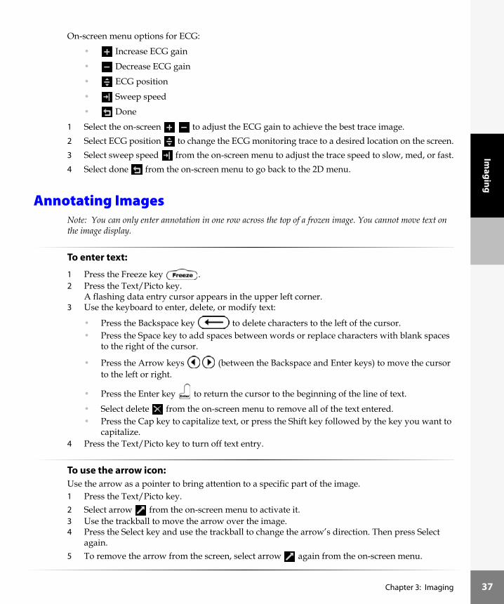
On-screen menu options for ECG:
• Increase ECG gain
• Decrease ECG gain
• ECG position
• Sweep speed
• Done
1 Select the on-screen to adjust the ECG gain to achieve the best trace image.2 Select ECG position to change the ECG monitoring trace to a desired location on the screen.3 Select sweep speed from the on-screen menu to adjust the trace speed to slow, med, or fast.4 Select done from the on-screen menu to go back to the 2D menu.
Annotating ImagesNote: You can only enter annotation in one row across the top of a frozen image. You cannot move text on the image display.
To enter text:
1 Press the Freeze key . 2 Press the Text/Picto key.
A flashing data entry cursor appears in the upper left corner.3 Use the keyboard to enter, delete, or modify text:
• Press the Backspace key to delete characters to the left of the cursor.• Press the Space key to add spaces between words or replace characters with blank spaces
to the right of the cursor.
• Press the Arrow keys (between the Backspace and Enter keys) to move the cursor to the left or right.
• Press the Enter key to return the cursor to the beginning of the line of text.
• Select delete from the on-screen menu to remove all of the text entered.• Press the Cap key to capitalize text, or press the Shift key followed by the key you want to
capitalize.4 Press the Text/Picto key to turn off text entry.
To use the arrow icon:Use the arrow as a pointer to bring attention to a specific part of the image.1 Press the Text/Picto key.2 Select arrow from the on-screen menu to activate it.3 Use the trackball to move the arrow over the image. 4 Press the Select key and use the trackball to change the arrow’s direction. Then press Select
again.5 To remove the arrow from the screen, select arrow again from the on-screen menu.
Chapter 3: Imaging 37

38
Imag
ing
To label the display with pre-defined text:See “To set up function key assignments:” on page 22, if necessary.
1 Press the Freeze key .2 Press the Text/Picto key.
A flashing data entry cursor appears in the upper left corner of the image display.
3 Press the Function key.4 Press a numeric key (1 through 6) corresponding to the assigned text with which you want to
label the display. Entering assigned text removes any other labeling on the display.Select delete from the on-screen menu to remove assigned text.
To display a pictograph and transducer marker for non-biopsy capable transducers:1 To turn on the picto icon , press the Patient key and select system setup from the on-screen
menu.2 Select OCR, TI, picto, Doppler.3 Select pictograph from the on-screen menu and set it to [on].4 Press the Patient key. A pictograph now appears in the upper right corner of the screen.
Note: The pictograph displayed depends on the transducer and exam type.
5 Press the Freeze key . 6 Press the Text/Picto key.
A flashing data entry cursor appears in the upper left corner of the image display and along with the following menu options:• Arrow
• Delete
• Picto
1 Select picto from the on-screen menu to display the next pictograph in the series for exam type. Each time you select picto from the on-screen menu:• The ratio next to the icon changes to show which pictograph in a set of pictographs has
been selected. For example 2/10 shows that there are 10 pictographs for this transducer and exam type, and the second pictograph has been selected from the 10 available pictographs.
• A different pictograph is displayed in the upper right corner of the screen for each transducer and exam type combination.
2 Use the trackball to position the transducer marker over the pictograph. The dot on one end of the transducer marker should correspond to the orientation marker in the displayed image.
3 Press the Select key and use the trackball to rotate the transducer marker to the proper angle.4 If necessary, press Select again and use the trackball to reposition the transducer marker.
Chapter 3: Imaging

Imaging
To display a pictograph and transducer marker for biopsy capable transducers:1 To turn on the picto , press the Patient key and select system setup from the on-screen menu.2 Select OCR, TI, picto, Doppler.3 Select pictograph from the on-screen menu and set it to [on].4 Press the Patient key. A pictograph now appears in the upper right corner of image display.5 Press the Freeze key . 6 Press the Text/Picto key.
A flashing data entry cursor appears in the upper left corner of the image display and along with the following menu options:
• Arrow
• Delete
• Next menu
7 To display the second menu, select next from the on-screen menu. The following menu appears:• Biopsy
• Picto
• Done
8 Select picto from the on-screen menu to display the next pictograph in the series for exam type.Each time you select picto from the on-screen menu:• The ratio next to the icon changes to show which pictograph in a set of pictographs has
been selected. For example 2/10 shows that there are 10 pictographs for this transducer and exam type, and the 2nd pictograph has been selected from the 10 available pictographs.
• A different pictograph is displayed in the upper right corner of the screen for each transducer and exam type combination.
9 When picto has been selected, use the trackball to position the transducer marker. The dot on one end of the transducer marker should correspond to the orientation marker in the displayed image.
10 Press the Select key then use the trackball to rotate the transducer marker to the proper angle.11 If necessary, press the Select key again and use the trackball to reposition the transducer marker.12 Select done from the on-screen menu to return to the previous menu.
Chapter 3: Imaging 39

40
Imag
ing
Needle GuidanceNote: The biopsy and needle guide features are dependent on transducer and exam type.The ultrasound system is equipped with a needle guidance feature. For detailed instructions on the use of the system, needle guidance accessories, and a list of compatible transducers, see the user guides for Biopsy and L25 Bracket and Needle.
Printing ImagesEnsure the printer is properly setup for operation with the system. See “To set up a recommended printer:” on page 19.
To print an image:
1 Press the Freeze key .
2 Press the Print/VCR key or Print key to print images.
To print all images:1 Save the images. (See “To save an image:” on page 41.)2 Press the Patient key.
A menu appears on which is listed stored images.3 Select stored images from the on-screen menu.4 Select print all images from the on-screen menu. All images print.
To cancel printing:
Press the Freeze key to stop printing.
Pin 1 orientation marker
L38/10-5 transducer
Chapter 3: Imaging

Imaging
Saving and Reviewing Images
To save an image:
1 Press the Freeze key .
2 Press the Save key .The image memory icon in the lower right section of the screen changes to show the image was saved.The number above the memory icon increases by 1 to show how many images have been saved. Depending on your configuration, you may be able to save up to 119 images in memory.
To review or delete individual images:1 Press the Patient key.
A menu appears on which is listed stored images.2 Select stored images from the on-screen menu.
A menu appears on which is listed review images.3 Select review images.
The last saved image appears with following menu:• Next image
• Previous image
• Delete
• Done
Note: Press the Menu key (to the left of Depth) to turn off or turn on this menu.
4 Use the cine arrow keys from the on-screen menu or the Cine arrow keys (above Freeze)
or the Arrow keys (next to the Enter key) to review the images.5 Select delete from the on-screen menu to remove the displayed image from the memory.6 A confirmation dialog appears and a menu on which is listed yes or no.7 Select yes to delete the image, or select no to cancel.8 When you are done, press the Freeze key to return to the menu.9 Press the Patient key to return to live imaging.
To delete all saved images:1 Press the Patient key.
A menu appears on which is listed stored images.2 Select stored images from the on-screen menu.
A menu appears on which is listed delete all images.3 Select delete all images from the on-screen menu.
A confirmation dialog appears and a menu on which is listed yes or no.4 Select yes to delete all images, or select no to cancel the operation.5 Select done from the on-screen menu until you return to live imaging.
Chapter 3: Imaging 41

42
Imag
ing
Recording ImagesNote: This feature is dependent on the hardware configuration.Ensure the VCR is properly setup for operation with the system. See “To set up the recommended VCR:” on page 21.
To start and stop the VCR:
1 Press the Print/VCR key or use the controls on the VCR to start VCR recording.
A dynamic VCR recording icon in the right section of the system display indicates that the VCR is recording.
2 Press the Print/VCR key a second time or use the controls on the VCR to stop recording.Note: If dynamic VCR recording icon does not appear, the VCR is not recording. To ensure proper recording, check:• Print/VCR key selection is set to Sony VCR (see “To set up the recommended VCR:” on
page 21)• Cables connected properly• Using recommended VCR• VCR power on
Refer to the VCR manufacturer’s instructions for recording and other functions.
After the ExamYou should check the battery after each use to ensure adequate charge is available for the next exam.
Caution: The VCR must be selected in the system setup to use the Print/VCR key to begin recording and to stop recording. It is recommended that if you are connecting a VCR and a printer, use the remote control to run the printer.
To prevent recording over images stored on a VCR videotape, make sure the proper peripheral is selected in system setup. With a VCR connected, the VCR will begin recording when the black and white (B&W) printer is selected in system setup. The only way to stop the VCR recording is to use the controls on the VCR.
Caution: SonoSite recommends that you clean transducers after each use. Continual, long-term exposure to gel can damage transducers. Refer to Chapter 6, “Troubleshooting and Maintenance” for cleaning and disinfecting procedures.
Chapter 3: Imaging

Meas. &
Calcs
Chapter 4: Measurements and Calculations
MeasurementsMeasurements and calculations are performed on frozen images. The following steps explain how to perform basic measurements in each imaging mode. Based on measurements taken, the SonoSite system automatically performs specific calculations and displays the results.
2D MeasurementsThe basic measurements that can be performed in 2D are:• Distance• Area (ellipse)• Circumference (ellipse)
To perform a distance measurement:1 On a frozen 2D image, press the Measure key.
Two calipers appear on-screen and the following menu options:• First caliper set
• Second caliper set
• Ellipse (circumference/area)
• Delete
• Calculations (calcs)Note: The two calipers are connected by a dotted line. The first caliper in the menu is active. When the calipers get farther apart, they increase in size; when the calipers get closer together, they decrease in size. The caliper line disappears as the calipers get closer together.
2 Use the trackball to position the first caliper .3 Press the Select key to activate the second caliper.4 Use the trackball to position the second caliper.
Note: The results update next to the caliper icon as you move the caliper, and the measurement is complete when you finish moving the calipers.
To perform a second distance measurement:1 Select the second set of calipers from the on-screen menu.
This will add another set of calipers to the image.2 Use the trackball and Select key as described in the preceding steps to complete the second
measurement.
Chapter 4: Measurements and Calculations 43

44
Mea
s. &
Cal
cs
To perform an ellipse measurement (area and circumference):1 Perform a distance measurement. 2 Select ellipse from the on-screen menu.
The circumference and the area appear in the lower left section of the screen.3 Use the trackball to adjust the size of the ellipse.4 Press the Select key to adjust the first caliper. Press Select again to adjust the second caliper.
Note: The results continue to update as the size is changed. The measurement is complete when you have finished adjusting the axes and position of the ellipse.Note: When an ellipse measurement is performed, only one distance measurement is available.
To turn off the ellipse:Select ellipse again from the on-screen menu.
To delete a measurement:1 Select the first set of calipers or the second set of calipers .2 Select delete from the on-screen menu.
To exit measurements:
Press the Freeze key to return to live imaging and exit measurements.
M-mode MeasurementsThe basic measurements that can be performed in M-mode are:• Distance (cm)• Time (seconds)• Heart Rate (bpm)Note: The time scale at the top of the screen has small marks at 200 ms intervals and large marks at one second intervals.
To perform a distance measurement:1 On a frozen M-mode trace, press the Measure key.2 A single caliper appears on-screen with the following menu options:
• Caliper set
• Heart Rate menu
• Delete
• Calculations (calcs)
3 Use the trackball to position the caliper .4 Press the Select key.
A second caliper appears on the screen.
Chapter 4: Measurements and Calculations

Meas. &
Calcs
5 Use the trackball to position the second caliper.The distance and time measurements are displayed in the upper left section of the screen.Note: The results update next to the caliper icon as you move the caliper, and the measurement is complete when you finish moving the calipers.
To delete the active measurement:Select delete from the on-screen menu.This will remove the active set of calipers from the screen.
To measure heart rate:1 On a frozen M-mode trace, press the Measure key.2 Select heart rate from the on-screen menu.
A vertical caliper appears as a dotted line on-screen with the following menu options:• Save
• Done3 Move the trackball right or left to position the first vertical caliper at the peak of the heart beat.4 Press the Select key.
A second vertical caliper appears on the screen.5 Move the trackball right to position the second vertical caliper at the peak of the next heart beat.
The heart rate (bpm) measurement is displayed in the upper left section of the screen.6 Select save from the on-screen menu to save the heart rate measurement to the patient
report.Note: This will overwrite the previous heart rate value entered under exam/patient information or the one measured in PW or CW Doppler. See “Preparing for the Exam” on page 25.
7 Select done from the on-screen menu to go back to basic measurements.
Doppler Measurements–Pulsed Wave (PW) and Continuous Wave (CW)Note: The Doppler scale must be set to cm/s for the following measurements. See “Using System Setup” on page 17.The basic measurements that can be performed in PW and CW Doppler are:• Acceleration (ACC)• Elapsed Time (ET)• Pressure Gradient (PGr), Cardiac exam type only: Chest, EC1, EC2, EC3• Resistive Index (RI)• Velocity• Ratio of two velocities (+/× or Systolic/Diastolic [S/D])
Chapter 4: Measurements and Calculations 45

46
Mea
s. &
Cal
cs
To measure a velocity (cm/s) and pressure gradient (PGr) in Doppler mode:Note: Pressure Gradient (PGr) in exam type cardiac only: Chest, EC1, EC2, EC3.1 On a frozen Doppler spectral trace, press the Measure key.
A single caliper appears on-screen with the following menu options:• First caliper set
• Second caliper set
• Automatic/manual trace
• Delete
• Calculations (calcs)2 Use the trackball to position the active caliper to the peak systolic wave form. (This is a single
caliper from the baseline).The velocity measurement is displayed in the upper left section of the screen.The Pressure Gradient (PGr) value is displayed in the lower left section of the screen.
To measure two velocities, resistive index (RI), +/× or S/D ratio, acceleration, and elapsed time:Note: RI and +/x or S/D ratio available in all modes except cardiac imaging.1 On a frozen Doppler spectral trace, press the Measure key.
A single caliper appears on-screen with the following menu options:• First caliper set
• Second caliper set
• Automatic/manual trace
• Delete
• Calculations (calcs)
2 Use the trackball to position the first caliper to a peak systolic wave form.3 Press the Select key or select the second caliper from the on-screen menu.
A second caliper appears on the screen.4 Use the trackball to position the second caliper at end diastole on the wave form.
A measurement taken with the second caliper provides a second velocity. The velocity measurements are displayed in the upper left section of the screen. When two velocity measurements are taken, RI, +/× or S/D ratio, acceleration, and elapsed time are displayed in the lower left section of the screen.Note: The results continue to update as the caliper positions are changed. The measurement is complete when you have finished adjusting the position of the calipers.
5 Press the Save key to save the image.Pressing the Save key will save the image but will not enter the results to the patient report.
Chapter 4: Measurements and Calculations

Meas. &
Calcs
The following table shows the trace results displayed by exam type:
Table 1: Trace Calculations by Exam Type
Cardiac Vascular OB/Gyn Abdominal and Other
Velocity Time Integral (VTI) X
Maximum Velocity (Vmax) X X X X
Mean Pressure Gradient (PGmean) X
Mean Velocity on Peak Trace (Vmean) X
Maximum Pressure Gradient (PGmax) X
Time Average Mean on Mean Trace (TAM)* X
+/× or Systolic/Diastolic (S/D) X X X
Pulsatility Index (PI) X X X
End Diastolic Velocity (EDV) X
Acceleration Time (AT) X X
Resistive Index (RI) X X X
Note: The automatic trace tool must be used to calculate the TAM.*
Chapter 4: Measurements and Calculations 47

48
Mea
s. &
Cal
cs
Figure 1 Trace Calculations of the Doppler Wave Form
To perform a manual trace in PW or CW Doppler:1 On a frozen Doppler spectral trace, press the Measure key.2 Select trace from the on-screen menu.
Note: The system defaults to manual trace or to the last trace method selected.
3 Select manual trace from the on-screen menu.A single caliper appears on the screen. This caliper is used to mark points on the trace.
4 Position the caliper at the beginning of the desired wave form, and press Select.Note: If calipers are not placed in the correct position, the calculation will not be performed accurately. See Figure 1.
5 Use the trackball to move the caliper to the next desired point on the wave form.6 Continue marking points to complete the trace.
The last point must be placed at the end of the wave form.Note: If an error is made, use the backspace key to delete the previous position.
7 Select SET from the on-screen menu to complete the trace and to display the results.
8 Press the Save key to save an image of the trace with the results displayed.If needed, select hide from the on-screen menu to remove the calculations, then press the Save key to save an image of the trace without the results displayed.
Time
Velocity
End Diastolic Velocity (EDV)
Peak Velocity (Vmax)
Acceleration Time (AT)
Velocity Time Integral (VTI)
Chapter 4: Measurements and Calculations

Meas. &
Calcs
To hide or show calculations in an automatic or manual trace:Select Hide from the on-screen menu to remove the calculations from the screen or select Show
from the on-screen menu to display the calculations on the screen.
Pressing done will remove the results. Pressing the Save key will save the image but will not enter the results to the patient report.
To perform an automatic trace in PW or CW Doppler:1 On a frozen Doppler spectral trace, press the Measure key.2 Select trace from the on-screen menu.3 Select automatic trace from the on-screen menu.
A vertical caliper appears on the screen.4 Use the trackball to position the first vertical caliper at the beginning of the wave form.5 Press the Select key.
Note: If calipers are not placed in the correct position, the calculation will not be performed accurately. See Figure 1.A second vertical caliper appears on the screen.
6 Use the trackball to position the second vertical caliper at the end of the wave form.7 Select SET from the on-screen menu to complete the trace and to display the results.
8 Press the Save key to save an image of the trace with the results displayed.If needed, select hide from the on-screen menu to remove the calculations, then press the Save key to save an image of the trace without the results displayed.
To hide or show calculations in an automatic or manual trace: Select Hide from the on-screen menu to remove the calculations from the screen or select Show
from the on-screen menu to display the calculations on the screen.
Pressing done will remove the results. Pressing the Save key will save the image but will not enter the results to the patient report.
Chapter 4: Measurements and Calculations 49

50
Mea
s. &
Cal
cs
Calculations
Volume CalculationThe following table shows the transducers and exam types that provide a volume calculation.
The following table shows the measurements required to complete the volume calculation. Volume measurements are completed in 2D mode.
To perform a volume calculation:
1 On a frozen 2D image, press the Measure key. 2 Select calcs from the on-screen menu.3 Select volume from the on-screen menu. (In OB and Gyn, select AFI Volume.)
A list of measurements (D1 D2 D3) appear in the lower left section of the screen with the active measurement result shown directly above.In OB and Gyn, the volume measurements (D1 D2 D3) appear after the quadrant measurements, Q1 Q2 Q3 Q4.
Warning: Verify that the patient information, date, and time settings are accurate. See Chapter 2 if necessary.
Before starting a new calculation, start a new patient record to delete the previous measurements. See “Preparing for the Exam” on page 25.
Table 2: Transducers and Exam Types
Transducer Exam Types for Volume
C60 OB, Gyn, Abdomen
C15 Abdomen, OB
C11 Vascular, Neonatal, Abdomen
ICT Gyn, OB, Prostate
L38 Breast, Small Parts, Vascular
Table 3: Volume Calculation
Measurement Calculation Result
D1 D2 D3 (2D distance) Vol (Volume)
Warning: Verify that the patient information, date, and time settings are accurate.
Chapter 4: Measurements and Calculations

Meas. &
Calcs
4 Press the Arrow keys (next to the Enter key) for the desired measurement.5 Perform the distance measurement.
6 Select save from the on-screen menu, or press the Enter key to save the measurement to the patient report. The saved measurement is shown in the upper left section of the screen, and a check mark is put in front of the measurement at the bottom of the screen.
7 Press the Save key to save the image with measurements to memory. (optional)Note: Save the image with the measurements and calculation results before proceeding to the next calculation measurement.
8 Press the Arrow keys for the next distance measurement in the calculation.9 Repeat these steps until all measurements have been completed.10 Select calcs from the on-screen menu to return to the list of calculations and patient report.
See “Viewing Patient Report” on page 69.11 Press done from the on-screen menu and then the Freeze key to return to live
imaging.Note: This must be done to turn calculations off, otherwise it remains on.
To view or repeat a saved measurement:
1 Use the Arrow keys (next to the Enter key) to select the measurement.The previously saved measurement results will appear in the upper left section of the screen.
2 Repeat the measurement.The new results appear directly above the measurement. You can compare the active measurement to the saved measurement.
3 To save the new measurement, select save from the on-screen menu, or press the Enter key
.Note: This will save the new measurement to the patient report and overwrite the previously saved measurement.
To delete a measurement:
1 Use the Arrow keys (next to the Enter key) to select the measurement.2 Select delete from the on-screen menu.
This will remove the measurement from the screen and the patient report.
Chapter 4: Measurements and Calculations 51

52
Mea
s. &
Cal
cs
Volume Flow CalculationThe following table shows the transducers and exam types that provide a volume flow calculation.
The following table shows the measurements required to complete the volume flow calculation.
Volume flow measurements are done in 2D and Doppler. Both measurements are required for the volume flow calculation. The Doppler sample volume should completely insonate the vessel. Note: The following factors should be considered when acquiring volume flow measurements:• Users should follow current medical practice for volume flow calculation applications.• The accuracy of the volume flow calculation is largely dependent on the user.• The factors identified in the literature that affect the accuracy are:
• Using the diameter method for 2D area• Difficulty ensuring uniform insonation of the vessel—The SonoSite system is limited to
sample volume sizes of 1, 2, 3, and 5 mm, depending on the transducer and exam type.• Precision in placing the caliper• Accuracy in angle correction
The considerations and degree of accuracy for volume flow measurements and calculations are discussed in the following reference:Allan, Paul L. et al. Clinical Doppler Ultrasound, 4th ed., Harcourt Publishers Limited. (2000), 36-38.
Table 4: Transducer and Exam Types
Transducer Exam Types for Volume Flow
C60 Abdomen
C15 Abdomen
C11 Vascular/ Abdomen
L38 Vascular
Table 5: Volume Flow Calculation
Measurement Calculation Result
D (2D distance)TAM (Doppler trace)
VF (Volume Flow)
Chapter 4: Measurements and Calculations

Meas. &
Calcs
To perform a volume flow calculation:
2D measurement:1 On a frozen 2D image, press the Measure key. 2 Select calcs from the on-screen menu.3 Select volume flow from the on-screen menu. 4 Perform the distance measurement.
5 Select save from the on-screen menu, or press the Enter key to save the measurement to the patient report. The saved measurement is shown in the upper left section of the screen, and a check mark is put in front of the measurement at the bottom of the screen.
6 Select calcs from the on-screen menu to return to the list of calculations and the patient report.
7 Press done from the on-screen menu and then the Freeze key to return to live imaging.Note: This must be done to turn calculations off, otherwise it remains on.
Doppler measurement:1 On a frozen Doppler spectral trace, press the Measure key.2 Select calcs from the on-screen menu.3 Select volume flow from the on-screen menu.4 Perform an automatic trace. See “To perform an automatic trace in PW or CW Doppler:” on
page 49.
5 Select save from the on-screen menu, or press the Enter key to save the measurement to the patient report.
6 Select calcs from the on-screen menu to return to the list of calculations and patient report.See “Viewing Patient Report” on page 69.
7 Press done from the on-screen menu and then the Freeze key to return to live imaging.Note: This must be done to turn calculations off, otherwise it remains on.
To view or repeat a saved measurement:
1 Use the Arrow keys (next to the Enter key) to select the measurement.The previously saved measurement results will appear in the upper left section of the screen.
2 Repeat the measurement.The new results appear directly above the measurement. You can compare the active measurement to the saved measurement.
3 To save the new measurement, select save from the on-screen menu, or press the Enter key
.Note: This will save the new measurement to the patient report and overwrite the previously saved measurement.
Warning: Verify that the patient information, date, and time settings are accurate.
Chapter 4: Measurements and Calculations 53

54
Mea
s. &
Cal
cs
To delete a measurement:
1 Use the Arrow keys (next to the Enter key) to select the measurement.2 Select delete from the on-screen menu.
This will remove the measurement from the screen and the patient report.
OB CalculationsReferences for these measurements and calculations are located in Chapter 7, “References”.The following table shows the transducers and exam types that provide OB calculations.
To select the calculation author see “Using System Setup” on page 17, if necessary.If you change the calc author during the exam, the common measurements are retained.For EDD by LMP calculation, make sure to enter the LMP (last menstrual period) date in exam/patient information. See “Preparing for the Exam” on page 25.The following table shows the measurements required to complete the desired OB calculation. OB measurements are done in 2D mode.
Table 6: Transducer and Exam Types
Transducer Exam Type
C60 OB, Gyn
C15 OB
ICT Gyn, OB
Warning: Make sure you have selected the OB or Gyn exam type and the OB calcs author for the OB table you intend to use. See Table 7 on page 55.
Chapter 4: Measurements and Calculations

Meas. &
Calcs
Note 1: The Estimated Fetal Weight calculation uses an equation that consists of one or more fetal biometry measurements. The author for the OB tables, which you choose in system setup, determines the measurements you must perform to obtain an EFW calculation. See “Using System Setup” on page 17, if necessary.Note 2: The fetal age is automatically calculated and displayed next to the OB measurement you selected. The average of the measurements taken is the AUA.Note 3: The system does not perform averaging of multiple measurements of the same anatomy. For example: if you measure femur length twice, the second measurement replaces the first and appears in the patient report, not the average of the two measurements.
Table 7: OB Calculations
Calculation Result OB Measurements Calculation Authors
Estimated Fetal Weight (EFW)(See note 1)
AC, FL Hadlock 1
BPD, AC, FL Hadlock 2
HC, AC, FL Hadlock 3
BPD, TTD Hansmann
BPD, FTA, FL Osaka U.
BPD, TTD, APTD, FL Tokyo U.
Fetal Age(See note 2)
BPD, HC, AC, FL Hadlock
BPD, OFD, HC, AC, TTD, FL Hansmann
BPD, FTA, FL Osaka U.
BPD, AC, FL Tokyo U.
BPD, HC, AC, FL Chitty
CRL HadlockHansmannTokyo U.Osaka U.
GS (GS1, GS2, GS3) HansmannNybergTokyo U.
Average Ultrasound Age (AUA) (See note 3)
Amniotic Fluid Index Q1, Q2, Q3, Q4 Jeng
Volume D1, D2, D3 Beyer
Chapter 4: Measurements and Calculations 55

56
Mea
s. &
Cal
cs
To perform OB measurements:
1 Select OB or Gyn exam type, and enter the LMP in the patient information.2 On a frozen 2D image, press the Measure key. 3 Select calcs from the on-screen menu.
If you change the calc author during the exam, reselect the desired calculation/label to reset the calculations/labels for the new author. The common measurements are retained.
4 Select the desired OB calculation package from the on-screen menu.A list of measurements appear in the lower left section of the screen with the active measurement result shown directly above.
5 Press the Arrow keys (next to the Enter key) for the desired measurement.6 Perform the measurement.
See “To perform a distance measurement:” on page 43 and “To perform an ellipse measurement (area and circumference):” on page 44.
7 Select save from the on-screen menu, or press the Enter key to save the measurement to the patient report. The saved measurement is shown in the upper left section of the screen, and a check mark is put in front of the measurement at the bottom of the screen.
8 Press the Save key to save the image with measurements to memory. (optional)Note: Save the image with the measurements and calculation results before proceeding to the next calculation measurement.
9 Press the Arrow keys for the next measurement in the calculation.10 Repeat these steps until all measurements have been completed.11 Select calcs from the on-screen menu to return to the list of calculations and patient report.
See “Viewing Patient Report” on page 69.12 Press done from the on-screen menu and then the Freeze key to return to live
imaging.Note: This must be done to turn calculations off, otherwise it remains on.
Warning: An accurate date and time are critical for accurate obstetrics calculations. Verify that the date and time are accurate before each use of the system. The system does not automatically adjust for daylight savings time changes.
Chapter 4: Measurements and Calculations

Meas. &
Calcs
To view or repeat a saved measurement:
1 Use the Arrow keys (next to the Enter key) to select the measurement.The previously saved measurement results will appear in the upper left section of the screen.
2 Repeat the measurement.The new results appear directly above the measurement. You can compare the active measurement to the saved measurement.
3 To save the new measurement, select save from the on-screen menu, or press the Enter key
.Note: This will save the new measurement to the patient report and overwrite the previously saved measurement.
To delete a measurement:
1 Use the Arrow keys (next to the Enter key) to select the measurement.2 Select delete from the on-screen menu.
This will remove the measurement from the screen and the patient report.
Vascular CalculationsThe following table shows the transducers and exam types that provide vascular calculations.
The following table lists the available carotid vascular measurements that can be stored to the report. Vascular measurements are done in PW or CW Doppler mode.
Table 8: Transducer and Exam Types
Transducer Exam Type
C11 Vascular
L38 Vascular
Table 9: Vascular Measurements
Vascular Measurement Description
PCCA Proximal Common Carotid Artery
MCCA Mid Common Carotid Artery (used in ICA/CCA ratio)
DCCA Distal Common Carotid Artery
Bulb Bulb
PICA Proximal Internal Carotid Artery
Chapter 4: Measurements and Calculations 57

58
Mea
s. &
Cal
cs
To assign a label to a vascular measurement:1 Select vascular exam type.2 On a frozen Doppler spectral trace, press the Measure key. 3 Select calcs from the on-screen menu.4 Select L or R carotid from the on-screen menu.
A list of measurement labels appear in the lower left section of the screen with the active measurement result shown directly above.
5 Press the Arrow keys (next to the Enter key) for the desired label for the measurement.6 Perform the measurement (only stores peak velocity).
Note: End diastolic measurements cannot be saved to the patient report.
7 Select save from the on-screen menu, or press the Enter key to save the measurement to the patient report. The saved measurement is shown in the upper left section of the screen, and a check mark is put in front of the measurement at the bottom of the screen.
8 Press the Save key to save the image with measurements to memory. (optional)Note: Save the image with the measurements and calculation results before proceeding to the next calculation measurement.
9 Press the Arrow keys (next to the Enter key) for the next measurement in the calculation.10 Repeat these steps until all measurements have been done.11 Select calcs from the on-screen menu to return to the list of calculations and patient report.
See “Viewing Patient Report” on page 69.12 Press done from the on-screen menu and then the Freeze key to return to live
imaging.Note: This must be done to turn calculations off, otherwise it remains on.
MICA Mid Internal Carotid Artery (used in ICA/CCA ratio)
DICA Distal Internal Carotid Artery
PECA Proximal External Carotid Artery
MECA Mid External Carotid Artery
DECA Distal External Carotid Artery
VArty Vertebral Artery
Table 9: Vascular Measurements (Continued)
Vascular Measurement Description
Warning: Verify that the patient information, date, and time settings are accurate.
Chapter 4: Measurements and Calculations

Meas. &
Calcs
To view or repeat a saved measurement:
1 Use the Arrow keys (next to the Enter key) to select the measurement.The previously saved measurement results will appear in the upper left section of the screen.
2 Repeat the measurement.The new results appear directly above the measurement. You can compare the active measurement to the saved measurement.
3 To save the new measurement, select save from the on-screen menu, or press the Enter key
.Note: This will save the new measurement to the patient report and overwrite the previously saved measurement.
To delete a measurement:
1 Use the Arrow keys (next to the Enter key) to select the measurement.2 Select delete from the on-screen menu.
This will remove the measurement from the screen and the patient report.
Cardiac CalculationsReferences for these measurements and calculations are located in Chapter 7, “References.”
The following table shows the transducers and exam types that provide cardiac calculations.
Warning: Verify that the patient information, date, and time settings are accurate.
Table 10: Transducer and Exam Type
Transducer Exam Type(Menu shown on the system)
C15C15 (SonoHeart)
ChestEC1, EC2, EC3
C11 Chest
Chapter 4: Measurements and Calculations 59

60
Mea
s. &
Cal
cs
The following table shows the measurements required to complete the desired cardiac calculation. The cardiac measurements are done in 2D and M-mode.
Table 11: Cardiac Calculations in 2D and M-mode
Imaging Mode Anatomy Cardiac Measurement Calculation Result
2D/M-mode LV RVWs CO
RVDs EF
IVSs SV
LVDs LVESV
LVPWs LVEDV
RVWd IVSFT
RVDd LVPWFT
IVSd LVDFS
LVDd
LVPWd
HR (in M-mode or Doppler)
LA/Ao LA LA/Ao
Ao
M-mode AoVS AoVS
LVET LVET
EF:SLOPE EF:SLOPE
EPSS EPSS
Chapter 4: Measurements and Calculations

Meas. &
Calcs
To perform cardiac calculations in 2D and M-mode:1 On a frozen 2D image or M-mode trace, press the Measure key. 2 Select calcs from the on-screen menu.3 Select the desired cardiac calculation package from the on-screen menu.
A list of measurements appear in the lower left section of the screen with the active measurement result shown directly above.
4 Press the Arrow keys (next to the Enter key) for the desired measurement.Note: As you advance through the LV measurements, the top caliper will automatically reposition to help you proceed with the next selected measurement.
5 Perform the cardiac measurement.
6 Select save from the on-screen menu, or press the Enter key to save the measurement to the patient report. The saved measurement is shown in the upper left section of the screen, and a check mark is put in front of the measurement at the bottom of the screen.
7 Press the Save key to save the image with measurements to memory. (optional)Note: Save the image with the measurements and calculation results before proceeding to the next calculation measurement.
8 Press the Arrow keys for the next measurement in the calculation.9 Repeat these steps until all measurements have been completed.10 Select calcs from the on-screen menu to return to the list of calculations and patient report.
See “Viewing Patient Report” on page 69.11 Press done from the on-screen menu and then the Freeze key to return to live
imaging.Note: This must be done to turn calculations off, otherwise it remains on.
To view or repeat a saved measurement:
1 Use the Arrow keys (next to the Enter key) to select the measurement.The previously saved measurement results will appear in the upper left section of the screen.
2 Repeat the measurement.The new results appear directly above the measurement. You can compare the active measurement to the saved measurement.
3 To save the new measurement, select save from the on-screen menu, or press the Enter key
.Note: This will save the new measurement to the patient report and overwrite the previously saved measurement.
Chapter 4: Measurements and Calculations 61

62
Mea
s. &
Cal
cs
To delete a measurement:
1 Use the Arrow keys (next to the Enter key) to select the measurement.2 Select delete from the on-screen menu.
This will remove the measurement from the screen and the patient report.The following table shows the measurements required to complete the desired cardiac calculation. The cardiac measurements are done in 2D, M-mode, PW Doppler, and CW Doppler mode.
Table 12: Cardiac Calculations in Doppler
Anatomy Cardiac Measurement Calculation Result
MV (Mitral Valve) EA
EE PGAA PGE:A
PHT (deceleration time) PHTMVA
dP:dT dP:dT
LVOT (Left Ventricular Outflow Tract)
VTI VTIVmaxPGmaxVmeanPGmean
Vmax or VTI VmaxPGmax
AV (Aortic Valve) VTI VTIVmax PGmax VmeanPGmean
LVOT D in 2DVTI or Vmax from LVOTVTI or Vmax from aorta
AVA
VTILVOT D in 2D
SV
VTIHRLVOT D in 2D
CO
Chapter 4: Measurements and Calculations

Meas. &
Calcs
To perform E, A, and Vmax measurements for PW or CW Doppler calculations:See Table 12 on page 62 for the measurements required for the cardiac calculation.1 On a frozen Doppler spectral trace, press the Measure key.2 Select calcs from the on-screen menu.3 Select MV, LVOT, AV, TV, or PV from the on-screen menu.
A list of measurements appear in the lower left section of the screen with the active measurement result shown directly above.
4 Press the Arrow keys (next to the Enter key) to select the desired peak velocity calculation.
5 Perform the velocity measurement.
6 Select save from the on-screen menu, or press the Enter key to save the measurement to the patient report. The saved measurement is shown in the upper left section of the screen, and a check mark is put in front of the measurement at the bottom of the screen.
7 Press the Save key to save the image with measurements to memory. (optional)Note: Save the image with the measurements and calculation results before proceeding to the next calculation measurement.
8 Press the Arrow keys for the next measurement in the calculation, if needed.9 Select calcs from the on-screen menu to return to the list of calculations and patient report.
See “Viewing Patient Report” on page 69.10 Press done from the on-screen menu and then the Freeze key to return to live
imaging.Note: This must be done to turn calculations off, otherwise it remains on.
TV (Tricuspid Valve) Vmax VmaxPGmax
dP:dT dP:dT
PV (Pulmonic Valve) VTI VTIVmaxPGmaxVmeanPGmean
Vmax or VTI VmaxPGmax
Table 12: Cardiac Calculations in Doppler (Continued)
Anatomy Cardiac Measurement Calculation Result
Chapter 4: Measurements and Calculations 63

64
Mea
s. &
Cal
cs
To perform a velocity time integral (VTI) calculation in PW or CW Doppler:Note: In addition to VTI results, this calculation will compute other results. See Table 12 on page 62.1 On a frozen Doppler spectral trace, press the Measure key.2 Select calcs from the on-screen menu.
Select LVOT, AV, or PV from the on-screen menu.A list of measurements appear in the lower left section of the screen with the active measurement result shown directly above.
3 Press the Arrow keys to select VTI.4 Perform automatic or manual trace.
See “To perform a manual trace in PW or CW Doppler:” on page 48 or “To perform an automatic trace in PW or CW Doppler:” on page 49.
5 Select save from the on-screen menu, or press the Enter key to save the measurement to the patient report. The saved measurement is shown in the upper left section of the screen, and a check mark is put in front of the measurement at the bottom of the screen.
6 Select calcs from the on-screen menu to return to the list of calculations and the patient report.See “Viewing Patient Report” on page 69.
7 Press done from the on-screen menu and then the Freeze key to return to live imaging.Note: This must be done to turn calculations off, otherwise it remains on.
To perform a pressure half time (PHT) calculation in PW or CW Doppler:Note: PHT is calculated by measuring deceleration time from peak to baseline.1 On a frozen Doppler spectral trace, press the Measure key.2 Select calcs from the on-screen menu.3 Select MV from the on-screen menu.
A list of measurements appear in the lower left section of the screen with the active measurement result shown directly above.
4 Press the Arrow keys (next to the Enter key) to select PHT.5 Use the trackball to position the first caliper at the peak.6 Press the Select key.
A second caliper appears on the screen.7 Use the trackball to position the second caliper along the EF slope.
8 Select save from the on-screen menu, or press the Enter key to save the measurement to the patient report. The saved measurement is shown in the upper left section of the screen, and a check mark is put in front of the measurement at the bottom of the screen.
9 Select calcs from the on-screen menu to return to the list of calculations and the patient report.See “Viewing Patient Report” on page 69.
Chapter 4: Measurements and Calculations

Meas. &
Calcs
10 Press done from the on-screen menu and then the Freeze key to return to live imaging.Note: This must be done to turn calculations off, otherwise it remains on.
To perform a delta pressure:delta time (dP:dT) calculation in PW or CW Doppler:Note: To perform the dP:dT measurements, the Doppler scale must include velocities of 300 cm/s or greater on the negative side of the baseline.1 On a frozen Doppler trace, press the Measure key.2 Select calcs from the on-screen menu.3 Select MV or TV from the on-screen menu.
A list of measurements appear in the lower left section of the screen with the active measurement result shown directly above.
4 Press the Arrow keys (next to the Enter key) to select dP:dT.A horizontal dotted line with an active caliper appears at 100 cm/s.
5 Use the trackball to position the first caliper along the beginning of the wave form at 100 cm/s.6 Press the Select key.
A second horizontal dotted line with an active caliper appears at 300 cm/s.7 Use the trackball to position the second caliper along the beginning of the wave form at 300
cm/s.
8 Select save from the on-screen menu, or press the Enter key to save the measurement to the patient report. The saved measurement is shown in the upper left section of the screen, and a check mark is put in front of the measurement at the bottom of the screen.
9 Select calcs from the on-screen menu to return to the list of calculations and the patient report.See “Viewing Patient Report” on page 69.
10 Press done from the on-screen menu and then the Freeze key to return to live imaging.Note: This must be done to turn calculations off, otherwise it remains on.
To perform aortic valve area (AVA) calculation in PW or CW Doppler:Note: This calculation requires a measurement taken in 2D and two measurements taken in Doppler. After the three measurements are completed and saved, the results appear in the patient report.2D measurement:1 On a frozen 2D image, press the Measure key.2 Select calcs from the on-screen menu.3 Select LVOT from the on-screen menu. 4 Perform the measurement.
5 Select save from the on-screen menu, or press the Enter key to save the measurement to the patient report.
6 Select calcs from the on-screen menu to return to the list of calculations and the patient report.
Chapter 4: Measurements and Calculations 65

66
Mea
s. &
Cal
cs
7 Press done from the on-screen menu and then the Freeze key to return to live imaging.Note: This must be done to turn calculations off, otherwise it remains on.
Doppler measurement from LVOT:1 On a frozen Doppler spectral trace, press the Measure key.2 Select calcs from the on-screen menu.3 Select LVOT from the on-screen menu.
A list of measurements appear in the lower left section of the screen with the active measurement result shown directly above.
4 Press the Arrow keys (next to the Enter key) to select VTI or Vmax.5 Perform the measurement.
See “To perform a manual trace in PW or CW Doppler:” on page 48 or “To perform an automatic trace in PW or CW Doppler:” on page 49.
6 Select save from the on-screen menu, or press the Enter key to save the measurement to the patient report.
7 Select calcs from the on-screen menu to return to the list of calculations and the patient report.
8 Press done from the on-screen menu and then the Freeze key to return to live imaging.Note: This must be done to turn calculations off, otherwise it remains on.
Doppler measurement from aorta:1 On a frozen Doppler spectral trace, press the Measure key.2 Select calcs from the on-screen menu.3 Select AV from on-screen menu.
4 Press the Arrow keys (next to the Enter key) to select VTI or Vmax.5 Perform the measurement for a VTI or Vmax.
See “To perform a manual trace in PW or CW Doppler:” on page 48 or “To perform an automatic trace in PW or CW Doppler:” on page 49.
6 Select save from the on-screen menu, or press the Enter key to save the measurement to the patient report.
7 Select calcs from the on-screen menu to return to the list of calculations and the patient report.After the three calculations are completed and saved, the AVA calculation results will appear on the patient report. See “Viewing Patient Report” on page 69.
8 Press done from the on-screen menu and then the Freeze key to return to live imaging.Note: This must be done to turn calculations off, otherwise it remains on.
Chapter 4: Measurements and Calculations

Meas. &
Calcs
To perform stroke volume (SV) calculation in PW or CW Doppler:Note: This calculation requires a measurement taken in 2D and one measurement taken in Doppler. After the measurements are completed and saved, the results appear in the patient report.2D measurement from LVOT:1 On a frozen 2D image, press the Measure key.2 Select calcs from the on-screen menu.3 Select LVOT from the on-screen menu.4 Perform the measurement.
5 Select save from the on-screen menu, or press the Enter key to save the measurement to the patient report.
6 Select calcs from the on-screen menu to return to the list of calculations and the patient report.
7 Press done from the on-screen menu and then the Freeze key to return to live imaging.Note: This must be done to turn calculations off, otherwise it remains on.
Doppler measurement from the aorta:1 On a frozen Doppler spectral trace, press the Measure key.2 Select calcs from the on-screen menu.3 Select AV from the on-screen menu.4 Perform the VTI measurement.
See “To perform a manual trace in PW or CW Doppler:” on page 48 or “To perform an automatic trace in PW or CW Doppler:” on page 49.
5 Select save from the on-screen menu, or press the Enter key to save the measurement to the patient report.
6 Select calcs from the on-screen menu to return to the list of calculations and the patient report.After the two calculations are completed and saved, the SV calculation result will appear on the patient report. See “Viewing Patient Report” on page 69.
7 Press done from the on-screen menu and then the Freeze key to return to live imaging.Note: This must be done to turn calculations off, otherwise it remains on.
To perform cardiac output (CO) calculation in PW or CW Doppler:Note: This calculation requires a stroke volume and a heart rate. After the measurements are completed and saved, the results appear in the patient report.1 On a frozen Doppler spectral trace, press the Measure key.2 Select calcs from the on-screen menu.3 Perform the calculation for SV.
See “To perform stroke volume (SV) calculation in PW or CW Doppler:” on page 67.4 Perform the calculation for HR.
See “To measure a heart rate (HR) in PW or CW Doppler:” on page 68.After the two calculations are completed and saved, the CO will show on the patient report. See “Viewing Patient Report” on page 69.
Chapter 4: Measurements and Calculations 67

68
Mea
s. &
Cal
cs
To measure a heart rate (HR) in PW or CW Doppler:Note: Heart Rate can also be taken in M-mode. See “To measure heart rate:” on page 45.1 On a frozen Doppler spectral trace, press the Measure key.2 Select calcs from the on-screen menu.3 Select desired cardiac calculation package from the on-screen menu.
Heart Rate is available in all cardiac packages.A list of measurements appear in the lower left section of the screen with the active measurement result shown directly above.
4 Press the Arrow keys (next to the Enter key) to select HR.5 Use the trackball to position the first vertical caliper at the beginning of the wave form.6 Press the Select key.
A second vertical caliper appears on the screen.7 Use the trackball to position the second vertical caliper at the beginning of the next wave form.
8 Select save from the on-screen menu, or press the Enter key to save the measurement to the patient report. The saved measurement is shown in the upper left section of the screen, and a check mark is put in front of the measurement at the bottom of the screen.
9 Select calcs from the on-screen menu to return to the list of calculations and the patient report.See “Viewing Patient Report” on page 69.
10 Press done from the on-screen menu and then the Freeze key to return to live imaging.Note: This must be done to turn calculations off, otherwise it remains on.
To view or repeat a saved measurement:
1 Use the Arrow keys (next to the Enter key) to select the measurement.The previously saved measurement results will appear in the upper left section of the screen.
2 Repeat the measurement.The new results appear directly above the measurement. You can compare the active measurement to the saved measurement.
3 To save the new measurement, select save from the on-screen menu, or press the Enter key
.Note: This will save the new measurement to the patient report and overwrite the previously saved measurement.
To delete a measurement:
1 Use the Arrow keys (next to the Enter key) to select the measurement.2 Select delete from the on-screen menu.
This will remove the measurement from the screen and the patient report.
Chapter 4: Measurements and Calculations

Meas. &
Calcs
Viewing Patient ReportNote: You may view the patient report using two options. If you access the patient report by selecting calc
from the on-screen menu, you will return to the frozen image. If you access the patient report by pressing the Patient key you will return to live imaging.
To view the patient report:1 Press the Patient key or, if available, select calcs from the on-screen menu.2 Select patient report from the on-screen menu.3 Select forward or back from the on-screen menu to navigate to additional report pages,
if needed.The current page number and total number of pages in the report are displayed in the lower left section of the screen.
4 Select done from the on-screen menu until you return to the image.Note: The pound sign symbol (###) is displayed on the patient report when an entry is not valid, e.g., value is too large or small.Note: The value for a calculation only appears when the calculation has been performed.
Chapter 4: Measurements and Calculations 69

70
Mea
s. &
Cal
cs
Chapter 4: Measurements and Calculations

Safety
Chapter 5: Safety
Please read this information before using the ultrasound system. It applies to the ultrasound system, transducers, accessories, and peripherals.A Warning describes precautions necessary to prevent injury or loss of life.A Caution describes precautions necessary to protect the products.
Electrical SafetyThis system meets EN60601-1, Class I/internally-powered equipment requirements and Type BF isolated patient-applied parts safety requirements. The ECG cable meets safety requirements of EN 60601-2-25 for Type CF patient-applied part.This system complies with the applicable medical equipment requirements published in the Canadian Standards Association (CSA), European Norm Harmonized Standard, and Underwriters Laboratories (UL) safety standards. See Chapter 8, “Specifications.”For maximum safety observe the following warnings and cautions:
Warning: To avoid discomfort or minor risk of patient injury, keep hot surfaces away from the patient.
Under certain circumstances, the transducer connector and back of the display enclosure can reach temperatures that exceed EN60601-1 limits for patient contact, therefore only the operator shall handle the system. This does not include the transducer face.
To avoid discomfort or minor risk of operator injury when handling the transducer connector, the system should not be operated for more than 60 minutes continuously in a live-scan mode (as opposed to freeze or sleep modes).
To avoid the risk of electrical shock or injury, do not open the system enclosures. All internal adjustments and replacements, except battery replacement, must be made by a qualified technician.
To avoid the risk of injury, do not operate the system in the presence of flammable gasses or anesthetics. Explosion can result.
To avoid the risk of electrical shock, use only properly grounded equipment. Shock hazards exist if the AC power adapter is not properly grounded. Grounding reliability can only be achieved when equipment is connected to a receptacle marked “Hospital Only” or “Hospital Grade” or the equivalent. The grounding wire must not be removed or defeated.
To avoid the risk of electrical shock, before using the transducer, inspect the transducer face, housing, and cable. Do not use the transducer, if the transducer or cable is damaged.
To avoid the risk of electrical shock, always disconnect the AC power adapter from the system before cleaning the system.
Chapter 5: Safety 71

72
Safe
ty
Warning: To avoid the risk of electrical shock, do not use any transducer that has been immersed beyond the specified cleaning or disinfection level. See Chapter 6, “Troubleshooting and Maintenance.”
To avoid the risk of electrical shock and fire hazard, inspect the AC power adapter cord and plug on a regular basis. Ensure they are not damaged.
To avoid the risk of electrical shock, use only accessories and peripherals recommended by SonoSite. Connection of accessories and peripherals not recommended by SonoSite could result in electrical shock. Contact SonoSite or your local representative for a list of accessories and peripherals available from or recommend by SonoSite.
To avoid the risk of electrical shock, use commercial grade peripherals recommended by SonoSite on battery power only. Do not connect these products to AC mains power when using the system to scan or diagnose a patient/subject. Contact SonoSite or your local representative for a list of the commercial grade peripherals available from or recommended by SonoSite.
To prevent injury, only use market cleared ECG electrodes and cables.
To avoid the risk of electrical shock to the patient/subject, ensure proper assembly of the ECG electrodes and cables.
To avoid the risk of electrical shock to the patient/subject, do not touch the system battery contacts while simultaneously touching a patient/subject.
To prevent injury to the operator/bystander, the transducer must be removed from patient contact before the application of a high-voltage defibrillation pulse.
Caution: Although your system has been manufactured in compliance with existing EMC/EMI requirements (EN60601-1-2), use of the system in the presence of an electromagnetic field can cause degradation of the ultrasound image. If this occurs often, SonoSite suggests a review of the system environment. Identify and remove the possible sources of the emissions or move your system.
Electrostatic discharge (ESD), or static shock, is a naturally occurring phenomenon. ESD is common in conditions of low humidity, which can be caused by heating or air conditioning. Static shock is a discharge of the electrical energy from a charged body to a lesser or non-charged body. The degree of discharge can be significant enough to cause damage to a transducer or an ultrasound system. The following precautions can help reduce ESD: anti-static spray on carpets, anti-static spray on linoleum, and anti-static mats.
Do not use the system if an error message appears on the image display: note the error code; call SonoSite or your local representative; turn off the system by pressing and holding the power switch until the system powers down.
To avoid increasing the system and transducer connector temperature, do not block the airflow to the ventilation holes on the back of the system.
Chapter 5: Safety

Safety
Equipment ProtectionTo protect your ultrasound system, transducer, and accessories, follow these precautions.
Battery SafetyTo avoid the battery bursting, igniting, or fumes from the battery and causing equipment damage, observe the following precautions:
Caution: The ECG cable emits electromagnetic interference when connected to the SonoSite system. It is not approved for use in-flight on aircraft.
Excessive bending or twisting of cables can cause a failure or intermittent operation.
Improper cleaning or disinfecting of any part of the system can cause permanent damage. For cleaning and disinfecting instructions, see Chapter 6, “Troubleshooting and Maintenance.”
Do not submerge the transducer connector in solution. The cable is not liquid-tight beyond the transducer connector/cable interface.
Do not use solvents such as thinner or benzene, or abrasive cleaners on any part of the system.
Remove the battery from the system if the system is not likely to be used for some time.
Do not spill liquid on the system.
Warning: The battery has a safety device. Do not disassemble or alter the battery.
Charge the batteries only when the ambient temperature is between 0° and 40°C (32° and 104°F).
Do not short-circuit the battery by directly connecting the positive and negative terminals with metal objects.
Do not heat the battery or discard it in a fire.
Do not expose the battery to temperatures over 60°C (140°F). Keep it away from fire and other heat sources.
Do not charge the battery near a heat source, such as a fire or heater.
Do not leave the battery in direct sunlight.
Recharge the battery only with the SiteCharge dual battery charger or the system.
Do not pierce the battery with a sharp object, hit it, or step on it.
Do not use a damaged battery.
Do not solder a battery.
Chapter 5: Safety 73

74
Safe
ty
Biological SafetyObserve the following precautions related to biological safety.
Warning: When connecting the battery to the SiteCharge dual battery charger or to the system, never reverse the polarity of the battery terminals.
The polarity of the battery terminals are fixed and cannot be switched or reversed. Do not force the battery into the system or the SiteCharge dual battery charger.
Do not connect the battery to an electrical power outlet.
Do not continue recharging the battery if it does not recharge after two successive six hour charging cycles.
Caution: To avoid the battery bursting, igniting, or fumes from the battery and causing equipment damage, observe the following precautions:
Do not immerse the battery in water or allow it to get wet.
Do not put the battery into a microwave oven or pressurized container.
If the battery leaks or emits an odor, remove it from all possible flammable sources.
If the battery emits an odor or heat, is deformed or discolored, or in any way appears abnormal during use, recharging or storage, immediately remove it and stop using it. If you have any questions about the battery, consult SonoSite or your local representative.
Store the battery between -20°C (-4°F) and 60°C (140°F).
Use only SonoSite batteries.
Warning: To prevent misdiagnosis, do not use the ECG trace to diagnosis cardiac rhythms. The SonoSite ECG option is a non-diagnostic feature.
To prevent injury, only use market cleared ECG electrodes and cables.
Non-medical (commercial) grade peripheral monitors have not been verified or validated by SonoSite as being suitable for diagnosis.
Do not use the system if it exhibits erratic or inconsistent behavior. Discontinuities in the scanning sequence are indicative of a hardware failure that must be corrected before use.
Do not use the system if it exhibits artifacts on the LCD screen, either within the clinical image or in the area outside of the clinical image. Artifacts are indicative of hardware and/or software errors that must be corrected before use.
Some transducer sheaths contain natural rubber latex and talc, which can cause allergic reactions in some individuals. Refer to 21 CFR 801.437, User labeling for devices that contain natural rubber.
Chapter 5: Safety

Safety
Electromagnetic Compatibility (EMC)The ultrasound system has been tested and found to comply with the electromagnetic compatibility (EMC) limits for medical devices to IEC 60601-1-2:2001. These limits are designed to provide reasonable protection against harmful interference in a typical medical installation.
Warning: Perform ultrasound procedures prudently. Use the ALARA (as low as reasonably achievable) principle.
SonoSite does not currently recommend a specific brand of acoustic standoff.
Caution: Medical electrical equipment requires special precautions regarding EMC and must be installed and operated according to these instructions. It is possible that high levels of radiated or conducted radio-frequency electromagnetic interference (EMI) from portable and mobile RF communications equipment or other strong or nearby radio-frequency sources, could result in performance disruption of the ultrasound system. Evidence of disruption may include image degradation or distortion, erratic readings, equipment ceasing to operate, or other incorrect functioning. If this occurs, survey the site to determine the source of disruption, and take the following actions to eliminate the source(s).
• Turn equipment in the vicinity off and on to isolate disruptive equipment.• Relocate or re-orient interfering equipment.• Increase distance between interfering equipment and your ultrasound system.• Manage use of frequencies close to ultrasound system frequencies.• Remove devices that are highly susceptible to EMI.• Lower power from internal sources within facility control (such as paging
systems).• Label devices susceptible to EMI.• Educate clinical staff to recognize potential EMI-related problems.• Eliminate or reduce EMI with technical solutions (such as shielding).• Restrict use of personal communicators (cell phones, computers) in areas with
devices susceptible to EMI.• Share relevant EMI information with others, particularly when evaluating new
equipment purchases which may generate EMI.• Purchase medical devices that comply with IEC 60601-1-2 EMC Standards
(3V/meter EMI immunity, limit interference level to 0.0014 V/meter).
Chapter 5: Safety 75

76
Safe
ty
Manufacturer’s DeclarationTable 1 and Table 2 document the intended use environment and EMC compliance levels of the system. For maximum performance, ensure that the system is used in the environments described in this table.The system is intended for use in the electromagnetic environment specified below.
Caution: To avoid the risk of increased electromagnetic emissions or decreased immunity, use only accessories and peripherals recommended by SonoSite. Connection of accessories and peripherals not recommended by SonoSite could result in malfunctioning of your ultrasound system or other medical electrical devices in the area. Contact SonoSite or your local representative for a list of accessories and peripherals available from or recommended by SonoSite.
Electrostatic discharge (ESD), or static shock, is a naturally occurring phenomenon. ESD is common in conditions of low humidity, which can be caused by heating or air conditioning. Static shock is a discharge of the electrical energy from a charged body to a lesser or non-charged body. The degree of discharge can be significant enough to cause damage to a transducer or an ultrasound system. The following precautions can help reduce ESD: anti-static spray on carpets, anti-static spray on linoleum, and anti-static mats.
Table 1: Manufacturer’s Declaration - Electromagnetic Emissions
Emissions Test Compliance Electromagnetic Environment
RF emissionsClSPR 11
Group 1 The SonoSite ultrasound system uses RF energy only for its internal function. Therefore, its RF emissions are very low and are not likely to cause any interference in nearby electronic equipment.
RF emissionsClSPR 11
Class A The SonoSite ultrasound system is suitable for use in all establishments other than domestic and those directly connected to the public low-voltage power supply network which supplies buildings used for domestic purposes.
Harmonic emissionsIEC 61000-3-2
Class A
Voltage fluctuations/flicker emissionsIEC 61000-3-3
Complies
Chapter 5: Safety

Safety
The system is intended for use in the electromagnetic environment specified below.
Table 2: Manufacturer’s Declaration - Electromagnetic Immunity
Immunity Test IEC 60601 Test Level Compliance Level Electromagnetic Environment
Electrostatic Discharge (ESD)IEC 61000-4-2
2.0KV, 4.0KV, 6.0KV contact2.0KV, 4.0KV, 8.0KV air
2.0KV, 4.0KV, 6.0KV contact2.0KV, 4.0KV, 8.0KV air
Floors should be wood, concrete or ceramic tile. If floors are covered with synthetic material, the relative humidity should be at least 30%.
Electrical fastTransient burstIEC 61000-4-4
2KV on the mains1KV on signal lines
2KV on the mains1KV on signal lines
Mains power quality should be that of a typical commercial or hospital environment.
SurgeIEC 61000-4-5
0.5KV, 1.0KV, 2.0KV on AC power lines to ground0.5KV, 1.0KV on AC power lines to lines
0.5KV, 1.0KV, 2.0KV on AC power lines to ground0.5KV, 1.0KV on AC power lines to lines
Mains power quality should be that of a typical commercial or hospital environment.
Voltage dips, short interruptions and voltage variations on power supply input lines IEC 61000-4-11
>5% UT(>95% dip in UT) for 0.5 cycle40% UT(60% dip In UT) for 5 cycles70% UT(30% dip in UT) for 25 cycles>5% UT(>95% dip In UT) for 5s
>5% UT(>95% dip in UT) for 0.5 cycle40% UT(60% dip In UT) for 5 cycles70% UT(30% dip in UT) for 25 cycles>5% UT(>95% dip In UT) for 5s
Mains power quality should be that of a typical commercial or hospital environment. If the user of the SonoSite ultrasound system requires continued operation during power mains interruptions, it is recommended that the SonoSite ultrasound system be powered from an uninterruptible power supply or a battery.
Power Frequency Magnetic FieldIEC 61000-4-8
3 A/m 3 A/m If image distortion occurs, it may be necessary to position the SonoSite ultrasound system further from sources of power frequency magnetic fields or to install magnetic shielding. The power frequency magnetic field should be measured in the Intended installation location to assure that it is sufficiently low.
Chapter 5: Safety 77

78
Safe
ty
Conducted RFIEC 61000-4-6
3 Vrms150 kHz to 80 MHz
3 Vrms Portable and mobile RF communications equipment should be used no closer to any part of the SonoSite ultrasound system including cables, than the recommended separation distance calculated from the equation applicable to the frequency of the transmitter.
Recommended Separation Distance
d = 1,2
Radiated RFIEC 61000-4-3
3 Vim80 MHz to 2.5 GHz
3 V/m d = 1,280 MHz to 800 MHz
d = 2,3800 MHz to 2,5 GHzWhere P is the maximum output power rating of the transmitter in watts (W) according to the transmitter manufacturer and d is the recommended separation distance in meters (m).
Radiated RFIEC 61000-4-3(continued)
Field strengths from fixed RF transmitters, as determined by an electromagnetic Site surveya, should be less than the compliance level in each frequency rangeb.Interference may occur in the vicinity of equipment marked with the following symbol:
(IEC 60417 No. 417-IEC-5140: “Source of non-ionizing radiation”)
Note: UT is the AC mains voltage prior to application of the test level.Note: At 80 MHz and 800 MHz, the higher frequency range applies.Note: These guidelines may not apply in all situations. Electromagnetic propagation is affected by absorption and reflection from structures, objects and people.
Table 2: Manufacturer’s Declaration - Electromagnetic Immunity (Continued)
Immunity Test IEC 60601 Test Level Compliance Level Electromagnetic Environment
P
P
P
Chapter 5: Safety

Safety
The ALARA PrincipleALARA is the guiding principle for the use of diagnostic ultrasound. Qualified sonographers, using good judgement and insight, determine the exposure that is as low as reasonably achievable. There are no rules sufficient to determine the correct response to every situation. So the sonographer keeps exposure low, bioeffects minimal, and images diagnostic.A thorough knowledge of the imaging modes, transducer capability, system setup, and scanning technique is necessary. The imaging mode determines the nature of the ultrasound beam. A stationary beam results in greater exposure than a scanned beam, which moves over an area, spreading exposure over that area. Transducer capability depends upon transducer frequency, penetration, resolution, and field of view. System setup establishes the starting point and determines control adjustments from that point. Scanning technique depends upon sonographer knowledge and experience. Anatomy, physiology, pathology, physics, and system operation are also factors to consider in applying the ALARA principle.There are variables which affect the way the sonographer implements the ALARA principle. These variables include body size, location of the bone relative to the focal point, attenuation in the body, and ultrasound exposure time. Exposure time is an especially useful variable, because it can be controlled by the sonographer. The ability to limit the exposure over time supports the ALARA principle.
Applying ALARAThe system imaging mode selected by the sonographer is determined by the information required. 2D imaging provides anatomical information; CPD imaging provides information about the energy or amplitude strength of the Doppler signal over time at a given anatomical location; DCPD imaging provides information about the presence of detectable blood flow and the direction of blood flow using the energy or amplitude strength of the Doppler signal over time at a given anatomical location. Pulsed wave Doppler and continuous wave Doppler provide quantitative information regarding blood flow through vessels within the body. Tissue Harmonic Imaging (THI) uses higher received frequencies to reduce clutter, artifact, and improve resolution. M-mode provides documentation and measurements of anatomical motion over time. Understanding the nature of the imaging mode being used allows the trained sonographer to apply the ALARA principle. Prudent use of ultrasound occurs when patient exposure to ultrasound is limited to the lowest ultrasound output for the shortest time necessary to achieve acceptable diagnostic results. Decisions that support prudent use are based on the type of patient, exam type, patient history, ease or difficulty of obtaining diagnostically useful information, and potential localized heating of the patient due to transducer surface temperature.
a. Field strengths from fixed transmitters such as base stations for radio (cellular/cordless) telephones and land mobile radios, amateur radio, AM and FM radio broadcast and TV broadcast cannot be predicted theoretically with accuracy. To assess the electromagnetic environment due to fixed RF transmitters, an electromagnetic site survey should be considered. If the measured field strength in the location in which the SonoSite ultrasound system is used exceeds the applicable RF compliance level above, the SonoSite ultrasound system should be observed to verify normal operation. If abnormal performance is observed, additional measures may be necessary, such as re-orienting or relocating the SonoSite ultrasound system.
b. Over the frequency range 150 kHz to 80 MHz, field strengths should be less than 3 V/m.
Chapter 5: Safety 79

80
Safe
ty
The system limits transducer surface temperature to 41°C (106°F). A power monitor protection circuit protects against over-current conditions. If the power monitor protection circuit senses an over-current condition, then the drive current to the transducer is shut off immediately, preventing over-heating of the transducer surface. Validation of the power monitor protection circuit is performed under normal system operation. The sonographer uses the system controls to adjust image quality and limit ultrasound output. The system controls are divided into three categories relative to output: controls that directly affect output, controls that indirectly affect output, and receiver controls.
Direct ControlsThe selection of exam type limits acoustic output through default. The acoustic output parameters that are set at default levels based on exam type are the mechanical index (MI) and the spatial peak temporal average intensity (ISPTA). The system does not exceed an MI of 1.0 for all exam types. It does not exceed 720 mW/cm2 for all exam types. The system does not exceed a thermal index (TI) of 1.0 for all modes except for PW Doppler and CPD on the C15 transducer.
Indirect ControlsThe controls that indirectly affect output are controls affecting imaging mode, optimization, transducer selection, freeze, and depth. The imaging mode determines the nature of the ultrasound beam. Tissue attenuation is directly related to transducer frequency. The higher the PRF (pulse repetition frequency), the more output pulses occur over a period of time. The pen optimization selection increases the output for 2D mode. The PRF, sample volume controls, and cursor position change the output for PW Doppler. The cursor position changes the output for CW Doppler.
Receiver ControlsThe receiver controls are the gain controls. Receiver controls do not affect output. They should be used, if possible, to improve image quality before using controls that directly or indirectly affect output.
Output DisplayThe system meets the AIUM output display standard for MI (see last reference listed in Related Guidance Documents below). The system and transducer combinations do not exceed an MI of 1.0 in any operating modes. Therefore, the MI output display is not required and is not displayed on the system for these modes.The system meets the output display standard for system for TI. A continuous real-time display of TI is displayed on the screen for any transducer and imaging mode combination where the TI can exceed 1.0. Currently the PW Doppler imaging mode and CPD with the C15 transducer are the only modes where the TI exceeds 1.0. The index is continuously displayed in increments of 0.1.The thermal index consists of three user selectable indices, and only one of these is displayed at any one time. In order to properly use the output display and meet the ALARA principle, the user selects an appropriate TI based on the specific exam being performed. SonoSite provides the AIUM Medical Ultrasound Safety reference which contains guidance on how to determine which TI is appropriate (see second reference listed in Related Guidance Documents below).
Chapter 5: Safety

Safety
Related Guidance Documents• Information for Manufacturers Seeking Marketing Clearance of Diagnostic Ultrasound Systems
and Transducers, FDA, 1997.• Medical Ultrasound Safety, American Institute of Ultrasound in Medicine (AIUM), 1994. (A
copy is included with each system.)• Acoustic Output Measurement Standard for Diagnostic Ultrasound Equipment, NEMA
UD2-1998.• Acoustic Output Measurement and Labeling Standard for Diagnostic Ultrasound Equipment,
American Institute of Ultrasound in Medicine, 1993.• Standard for Real-Time Display of Thermal and Mechanical Acoustic Output Indices on
Diagnostic Ultrasound Equipment, American Institute of Ultrasound in Medicine, 1998.
Acoustic Output MeasurementSince the initial use of diagnostic ultrasound, the possible human biological effects (bioeffects) from ultrasound exposure have been studied by various scientific and medical institutions. In October 1987, the American Institute of Ultrasound in Medicine (AIUM) ratified a report prepared by its Bioeffects Committee (Bioeffects Considerations for the Safety of Diagnostic Ultrasound, J Ultrasound Med., Sept. 1988: Vol. 7, No. 9 Supplement), sometimes referred to as the Stowe Report, which reviewed available data on possible effects of ultrasound exposure. Another report “Bioeffects and Safety of Diagnostic Ultrasound,” dated January 28, 1993 provides more current information.The acoustic output for this ultrasound system has been measured and calculated in accordance with the “Acoustic Output Measurement Standard for Diagnostic Ultrasound Equipment” (NEMA UD 2-1998, and the “Standard for Real-Time Display of Thermal and Mechanical Acoustic Output Indices on Diagnostic Ultrasound Equipment” (AIUM and NEMA 1998).
In Situ, Derated, and Water Value IntensitiesAll intensity parameters are measured in water. Since water does not absorb acoustic energy, these water measurements represent a worst case value. Biological tissue does absorb acoustic energy. The true value of the intensity at any point depends on the amount and type of tissue and the frequency of the ultrasound passing through the tissue. The intensity value in the tissue, In Situ, has been estimated by using the following formula:
In Situ = Water [e-(0.23alf)]where:
In Situ = In Situ intensity valueWater = Water intensity value e = 2.7183a = attenuation factortissue = a(dB/cm-MHz)brain = 0.53heart = 0.66kidney = 0.79liver = 0.43muscle = 0.55
Chapter 5: Safety 81

82
Safe
ty
l = skinline to measurement depth in cm.f = center frequency of the transducer/system/mode combination in MHz.Since the ultrasonic path during the exam is likely to pass through varying lengths and types of tissue, it is difficult to estimate the true In Situ intensity. An attenuation factor of 0.3 is used for general reporting purposes; therefore, the In Situ value commonly reported uses the formula:
In Situ (derated) = Water [e -(0.069lf)]Since this value is not the true In Situ intensity, the term “derated” is used to qualify it.The maximum derated and the maximum water values do not always occur at the same operating conditions; therefore, the reported maximum water and derated values may not be related by the In Situ (derated) formula. For example: a multi-zone array transducer that has maximum water value intensities in its deepest zone, but also has the smallest derating factor in that zone. The same transducer may have its largest derated intensity in one of its shallowest focal zones.
Tissue Models and Equipment SurveyTissue models are necessary to estimate attenuation and acoustic exposure levels In Situ from measurements of acoustic output made in water. Presently, available models may be limited in their accuracy because of varying tissue paths during diagnostic ultrasound exposures and uncertainties in the acoustic properties of soft tissues. No single tissue model is adequate for predicting exposures in all situations from measurements made in water, and continued improvement and verification of these models is necessary for making exposure assessments for specific exam types.A homogeneous tissue model with attenuation coefficient of 0.3 dB/cm-MHz throughout the beam path is commonly used when estimating exposure levels. The model is conservative in that it overestimates the In Situ acoustic exposure when the path between the transducer and site of interest is composed entirely of soft tissue. When the path contains significant amounts of fluid, as in many first and second-trimester pregnancies scanned transabdominally, this model may underestimate the In Situ acoustic exposure. The amount of underestimation depends upon each specific situation.Fixed-path tissue models, in which soft tissue thickness is held constant, sometimes are used to estimate In Situ acoustic exposures when the beam path is longer than 3 cm and consists largely of fluid. When this model is used to estimate maximum exposure to the fetus during transabdominal scans, a value of 1 dB/cm-MHz may be used during all trimesters.Existing tissue models that are based on linear propagation may underestimate acoustic exposures when significant saturation due to non-linear distortion of beams in water is present during the output measurement.The maximum acoustic output levels of diagnostic ultrasound devices extend over a broad range of values:• A survey of 1990-equipment models yielded MI values between 0.1 and 1.0 at their highest
output settings. Maximum MI values of approximately 2.0 are known to occur for currently available equipment. Maximum MI values are similar for real-time 2D and M-mode imaging.
• Computed estimates of upper limits to temperature elevations during transabdominal scans were obtained in a survey of 1988 and 1990 pulsed Doppler equipment. The vast majority of models yielded upper limits less than 1° and 4°C (1.8° and 7.2°F) for exposures of first-trimester fetal tissue and second-trimester fetal bone, respectively. The largest values obtained were approximately 1.5°C (2.7°F) for first-trimester fetal tissue and 7°C (12.6°F) for second-trimester fetal bone. Estimated maximum temperature elevations given here are for a “fixed path” tissue model and are for devices having ISPTA values greater than 500 mW/cm2. The temperature elevations for fetal bone and tissue were computed based on calculation procedures given in Sections 4.3.2.1-4.3.2.6 in “Bioeffects and Safety of Diagnostic Ultrasound” (AIUM, 1993).
Chapter 5: Safety

Safety
Intended UsesThe intended uses for each exam type are contained here. See the intended transducer for exam type in Table 1, “Transducer, Exam Type, and Imaging Mode” on page 27.
Abdominal Imaging ApplicationsThis system transmits ultrasound energy into the abdomen of patients using 2D, M-mode, color power Doppler (CPD), directional color power Doppler (DCPD), Tissue Harmonic Imaging (THI), pulsed wave (PW) Doppler, and continuous wave (CW) Doppler to obtain ultrasound images. The liver, kidneys, pancreas, spleen, gallbladder, bile ducts, transplanted organs, abdominal vessels, and surrounding anatomical structures can be assessed for the presence or absence of pathology transabdominally.
Cardiac Imaging ApplicationsThis system transmits ultrasound energy into the thorax of patients using 2D, M-mode, directional color power Doppler (DCPD), Tissue Harmonic Imaging (THI), pulsed wave (PW) Doppler, and continuous wave (CW) Doppler to obtain ultrasound images. The heart, cardiac valves, great vessels, surrounding anatomical structures, overall cardiac performance, and heart size can be assessed for the presence or absence of pathology. The heart can be imaged transthoracic.The patient’s electrocardiogram (ECG) may be obtained and is used for accurate timing of diastolic and systolic function.
Gynecology and Infertility Imaging ApplicationsThis system transmits ultrasound energy in the pelvis and lower abdomen using 2D, M-mode, color power Doppler (CPD), directional color power Doppler (DCPD), Tissue Harmonic Imaging (THI), and pulsed wave (PW) Doppler to obtain ultrasound images. The uterus, ovaries, adnexa, and surrounding anatomical structures can be assessed for the presence or absence of pathology. This system can be used to monitor ovarian follicle size for fertility procedures and as an aid in chorionic villi sampling (CVS) procedures.
Interventional and Intraoperative Imaging ApplicationsThis system transmits ultrasound energy into the various parts of the body using 2D, M-mode, color power Doppler (CPD), directional color power Doppler (DCPD), Tissue Harmonic Imaging (THI), pulsed wave (PW) Doppler, and continuous pulsed wave (CW) Doppler to obtain ultrasound images that provide guidance during interventional and intraoperative procedures. This system can be used to provide ultrasound guidance for biopsy and drainage procedures, vascular line placement, peripheral nerve blocks, ova harvesting, amniocentesis and other obstetrical procedures, and provide assistance during abdominal, vascular, and neurological intraoperative procedures.
Warning: The ECG is not used to diagnose cardiac arrhythmias and is not designed for long term cardiac rhythm monitoring.
Warning: This system is not intended for use in providing guidance for central nerve blocks, i.e., the brain and spinal cord, or for ophthalmic applications.
Chapter 5: Safety 83

84
Safe
ty
Obstetrical Imaging ApplicationsThis system transmits ultrasound energy into the pelvis of pregnant women using 2D, M-mode, color power Doppler (CPD), directional color power Doppler (DCPD), Tissue Harmonic Imaging (THI), and pulsed wave (PW) Doppler to obtain ultrasound images. The fetal anatomy, viability, estimated fetal weight, gestational age, amniotic fluid, and surrounding anatomical structures can be assessed for the presence or absence of pathology transabdominally or transvaginally. CPD and DCPD imaging is intended for high-risk pregnant women. High-risk pregnancy indications include, but are not limited to, multiple pregnancy, fetal hydrops, placental abnormalities, as well as maternal hypertension, diabetes, and lupus.
Pediatric and Neonatal Imaging ApplicationsThis system transmits ultrasound energy into the pediatric or neonatal patients using 2D, M-mode, color power Doppler (CPD), directional color power Doppler (DCPD), pulsed wave (PW) and continuous wave (CW) Doppler to obtain ultrasound images. The pediatric abdominal, pelvic and cardiac anatomy, pediatric hips, neonatal heads, and surrounding anatomical structures can be assessed for the presence or absence of pathology.
Prostate Imaging ApplicationsThis system transmits ultrasound energy into the prostate of an adult male using 2D, M-mode, color power Doppler (CPD), and pulsed wave (PW) Doppler to obtain ultrasound images. The prostate gland can be assessed for the presence or absence of pathology.
Superficial Imaging ApplicationsThis system transmits ultrasound energy into various parts of the body using 2D, M-mode, color power Doppler (CPD), and pulsed wave (PW) Doppler to obtain ultrasound images. The breast, thyroid, testicle, lymph nodes, hernias, musculoskeletal structures, soft tissue structures, and surrounding anatomical structures can be assessed for the presence or absence of pathology. This system can be used to provide ultrasound guidance for biopsy and drainage procedures, vascular line placement, and peripheral nerve blocks.
Warning: To prevent injury or misdiagnosis do not use this system for Percutaneous Umbilical Blood Sampling (PUBS) or in vitro Fertilization (IVF) The system has not been validated to be proven effective for these two uses.
CPD or DCPD images can be used as an adjunctive method, not as a screening tool, for the detection of structural anomalies of the fetal heart and as an adjunctive method, not as a screening tool for the diagnosis of Intrauterine Growth Retardation (IUGR).
Warning: Warning: This system is not intended for use in providing guidance for central nerve blocks, i.e., the brain and spinal cord, or for ophthalmic applications.
Chapter 5: Safety

Safety
Vascular Imaging ApplicationsThis system transmits ultrasound energy into the various parts of the body using 2D, M-mode, color power Doppler (CPD), Tissue Harmonic Imaging (THI), and pulsed wave (PW) Doppler to obtain ultrasound images. The carotid arteries, deep veins in the arms and legs, superficial veins in the arms and legs, great vessels in the abdomen, and various small vessels feeding organs can be assessed for the presence or absence of pathology.
About the Acoustic Output TableThe terms used in the acoustic output tables follow:Transducer Model is the SonoSite transducer model.
Table 3: Acoustic Output Terms and Definitions
Term Definition
ISPTA.3 Derated spatial peak, temporal average intensity in units of milliwatts/cm2.
TI type Applicable thermal index for the transducer, imaging mode, and exam type.
TI value Thermal index value for the transducer, imaging mode, and exam type.
MI Mechanical index.
Ipa.3@MImax Derated pulse average intensity at the maximum MI in units of W/cm2.
TIS (Soft tissue thermal index) is a thermal index related to soft tissues. TIS scan is the soft tissue thermal index in an auto-scanning mode. TIS non-scan is the soft tissue thermal index in the non-autoscanning mode.
TIB (Bone thermal index) is a thermal index for applications in which the ultrasound beam passes through soft tissue and a focal region is in the immediate vicinity of bone. TIB non-scan is the bone thermal index in the non-autoscanning mode.
TIC (Cranial bone thermal index) is the thermal index for applications in which the ultrasound beam passes through bone near the beam entrance into the body.
Aaprt Area of the active aperture measured in cm2.
Pr.3 Derated peak rarefactional pressure associated with the transmit pattern giving rise to the value reported under MI (Megapascals).
Wo Ultrasonic power, except for TISscan, in which case it is the ultrasonic power passing through a one centimeter window in units of milliwatts.
W.3(z1) Derated ultrasonic power at axial distance z1 in units of milliwatts.
Chapter 5: Safety 85

86
Safe
ty
ISPTA.3(z1) Derated spatial-peak temporal-average intensity at axial distance z1 (milliwatts per square centimeter).
z1 Axial distance corresponding to the location of maximum [min(W.3(z), ITA.3(z) x 1 cm2)], where z > zbp in centimeters.
zbp 1.69 in centimeters.
zsp For MI, it is the axial distance at which pr.3 is measured. For TIB, it is the axial distance at which TIB is a global maximum (i.e., zsp = zb.3) in centimeters.
deq(z) Equivalent beam diameter as a function of axial distance z, and is equal to
, where ITA(z) is the temporal-average intensity as a function of z in centimeters.
fc Center frequency in MHz.
Dim. of Aaprt Active aperture dimensions for the azimuthal (x) and elevational (y) planes in centimeters.
PD Pulse duration (microseconds) associated with the transmit pattern giving rise to the reported value of MI.
PRF Pulse repetition frequency associated with the transmit pattern giving rise to the reported value of MI in Hertz.
pr@PIImax Peak rarefactional pressure at the point where the free-field, spatial-peak pulse intensity integral is a maximum in Megapascals.
deq@PIImax Equivalent beam diameter at the point where the free-field, spatial-peak pulse intensity integral is a maximum in centimeters.
FL Focal length, or azimuthal (x) and elevational (y) lengths, if different measured in centimeters.
Table 3: Acoustic Output Terms and Definitions (Continued)
Term Definition
Aaprt( )
4 π( )⁄( ) Wo( ) ITA z( )( )⁄( )
Chapter 5: Safety

Safety
Acoustic Output TablesTable 4 indicates the acoustic output for all system and transducer combinations with a thermal index and mechanical index less than one.
Table 5 through Table 11 indicate the acoustic output for the system and transducer combinations with a thermal index equal to or greater than one. This includes all transducers used in PW Doppler mode as well as the C15 in CPD mode.
Table 4: Acoustic Output
Transducer Model ISPTA.3 TI Type TI Value MI Ipa.3@MImax
C8/8-5 MHz 183.4 TIC 0.9 0.9 222.7
C11/7-4 MHz 166 TIC 0.7 0.5 29.63
C15/4-2 MHz 84 TIC 0.7 0.7 48.06
C60/5-2 MHz 22 TIC 0.4 0.4 18.26
HST/10-5 MHz 176 TIB 0.2 0.3 12.42
ICT/7-4 MHz 19 TIC 0.3 0.4 31.14
L25/10-5 MHz 37 TIC 0.3 0.6 64.61
L38/10-5 MHz 169 TIC 0.5 0.6 111.3
Chapter 5: Safety 87

88
Safe
ty
(a) This index is not required for this operating mode; value is <1.(b) This transducer is not intended for transcranial or neonatal cephalic uses.# No data are reported for this operating condition since the global maximum index value is not reported for
the reason listed. (Reference Global Maximum Index Value line.)— Data is not applicable for this transducer/mode.
Table 5: Transducer Model: C8/8-5 Operating Mode: PW Doppler
Index Label M.I.
TIS TIB
TICScan
Non-scanNon-scan
Aaprt≤1 Aaprt>1
Global Maximum Index Value (a) — (a) — 1.4 (a)
Ass
ocia
ted
Aco
ustic
Para
met
er
pr.3 (MPa) #
W0 (mW) — # 19.331 #
min of [W.3(z1),ITA.3(z1)]
(mW) —
z1 (cm) —
zbp (cm) —
zsp (cm) # 1.8
deq(zsp) (cm) 0.2188
fc (MHz) # — # — 5.33 #
Dim of Aaprt X (cm) — # — 0.672 #Y (cm) — # — 0.4 #
Oth
er In
form
atio
n
PD (μsec) #PRF (Hz) #pr@PIImax (MPa) #
deq@Pllmax (cm) 0.179
Focal Length FLx (cm) — # — #
FLy (cm) — # — #
IPA.3@MImax (W/cm2) #
Ope
ratin
gCo
ntro
l Co
nditi
ons
Control 1: Exam Type AnyControl 2: Sample Volume 3 mmControl 3: PRF 15625Control 4: Sample Vol. Position zone 5
2.75 to 3.85 cm
Chapter 5: Safety

Safety
(a) This index is not required for this operating mode; value is <1.(b) This transducer is not intended for transcranial or neonatal cephalic uses.# No data are reported for this operating condition since the global maximum index value is not reported for
the reason listed. (Reference Global Maximum Index Value line.)— Data is not applicable for this transducer/mode.
Table 6: Transducer Model: C11 Operating Mode: PW Doppler
Index Label M.I.
TIS TIB
TICScan
Non-scanNon-scan
Aaprt≤1 Aaprt>1
Global Maximum Index Value (a) — < 1 — 1.5 1
Ass
ocia
ted
Aco
ustic
Para
met
er
pr.3 (MPa) #
W0 (mW) — # 20.529 20.529
min of [W.3(z1),ITA.3(z1)]
(mW) —
z1 (cm) —
zbp (cm) —
zsp (cm) # 0.8
deq(zsp) (cm) 0.453
fc (MHz) # — # — 5.33 5.33
Dim of Aaprt X (cm) — # — 0.378 0.378
Y (cm) — # — 0.6 0.6
Oth
er In
form
atio
n
PD (μsec) #PRF (Hz) #pr@PIImax (MPa) #
deq@Pllmax (cm) 0.232
Focal Length FLx (cm) — # — 3.0
FLy (cm) — # — 2.0
IPA.3@MImax (W/cm2) #
Ope
ratin
gCo
ntro
l Co
nditi
ons
Control 1: Exam Type Any AnyControl 2: Sample Volume 3 mm 3 m
mControl 3: PRF 10417 1041
7Control 4: Sample Vol. Position < 15 mm <15
mm
Chapter 5: Safety 89

90
Safe
ty
(a) This index is not required for this operating mode; value is <1.(b) This transducer is not intended for transcranial or neonatal cephalic uses.# No data are reported for this operating condition since the global maximum index value is not reported for
the reason listed. (Reference Global Maximum Index Value line.)— Data is not applicable for this transducer/mode.
Table 7: Transducer Model: C15 Operating Mode: Color Power Doppler
Index Label M.I.
TIS TIB
TICScan
Non-scanNon-scan
Aaprt≤1 Aaprt>1
Global Maximum Index Value (a) — <1 — 1.2 (b)
Ass
ocia
ted
Aco
ustic
Para
met
er
pr.3 (MPa) #
W0 (mW) — # 17.502 #
min of [W.3(z1),ITA.3(z1)]
(mW) —
z1 (cm) —
zbp (cm) —
zsp (cm) # 1.0
deq(zsp) (cm) 0.40
fc (MHz) # — # — 5.32 #
Dim of Aaprt X (cm) — # — 0.72 #Y (cm) — # — 0.4 #
Oth
er In
form
atio
n
PD (μsec) #PRF (Hz) #pr@PIImax (MPa) #
deq@Pllmax (cm) 0.169
Focal Length FLx (cm) — # — #
FLy (cm) — # — #
IPA.3@MImax (W/cm2) #
Ope
ratin
gCo
ntro
l Co
nditi
ons
Control 1: Exam Type AnyControl 2: Sample Volume 2 mmControl 3: PRF 10417,
15625, or 20833
Control 4: Sample Vol. Position 27.5–37.5 mm
Chapter 5: Safety

Safety
(a) This index is not required for this operating mode; value is <1.(b) This transducer is not intended for transcranial or neonatal cephalic uses.# No data are reported for this operating condition since the global maximum index value is not reported for
the reason listed. (Reference Global Maximum Index Value line.)— Data is not applicable for this transducer/mode.
Table 8: Transducer Model: C15 Operating Mode: PW Doppler
Index Label M.I.
TIS TIB
TICScan
Non-scanNon-scan
Aaprt≤1 Aaprt>1
Global Maximum Index Value (a) — — < 1 2.5 (b)
Ass
ocia
ted
Aco
ustic
Para
met
er
pr.3 (MPa) #
W0 (mW) — — 83.075 #
min of [W.3(z1),ITA.3(z1)]
(mW) #
z1 (cm) #
zbp (cm) #
zsp (cm) # 3.648
deq(zsp) (cm) 0.45
fc (MHz) # — — # 2.17 #
Dim of Aaprt X (cm) — — # 1.2478 #Y (cm) — — # 1.3 #
Oth
er In
form
atio
n
PD (μsec) #PRF (Hz) #pr@PIImax (MPa) #
deq@Pllmax (cm) 0.44
Focal Length FLx (cm) — — # #
FLy (cm) — — # #
IPA.3@MImax (W/cm2) #
Ope
ratin
gCo
ntro
l Co
nditi
ons Control 1: Exam Type Any
Control 2: Sample Volume 5 mmControl 3: PRF 10417Control 4: Sample Vol. Position < 35 mm
Chapter 5: Safety 91

92
Safe
ty
(a) This index is not required for this operating mode; value is <1.(b) This transducer is not intended for transcranial or neonatal cephalic uses.# No data are reported for this operating condition since the global maximum index value is not reported for
the reason listed. (Reference Global Maximum Index Value line.)— Data is not applicable for this transducer/mode.
Table 9: Transducer Model: C60 Operating Mode: PW Doppler
Index Label M.I.
TIS TIB
TICScan
Non-scanNon-scan
Aaprt≤1 Aaprt>1
Global Maximum Index Value (a) — — < 1 1.9 (b)
Ass
ocia
ted
Aco
ustic
Para
met
er
pr.3 (MPa) #
W0 (mW) — — 57.633 #
min of [W.3(z1),ITA.3(z1)]
(mW) #
z1 (cm) #
zbp (cm) #
zsp (cm) # 1.875
deq(zsp) (cm) 0.775
fc (MHz) # — — # 2.99 #
Dim of Aaprt X (cm) — — # 0.875 #Y (cm) — — # 1.3 #
Oth
er In
form
atio
n
PD (μsec) #PRF (Hz) #pr@PIImax (MPa) #
deq@Pllmax (cm) 0.329
Focal Length FLx (cm) — — # #
FLy (cm) — — # #
IPA.3@MImax (W/cm2) #
Ope
ratin
gCo
ntro
l Co
nditi
ons Control 1: Exam Type Any
Control 2: Sample Volume 5 mmControl 3: PRF 6250Control 4: Sample Vol. Position < 35 mm
Chapter 5: Safety

Safety
(a) This index is not required for this operating mode; value is <1.(b) This transducer is not intended for transcranial or neonatal cephalic uses.# No data are reported for this operating condition since the global maximum index value is not reported for
the reason listed. (Reference Global Maximum Index Value line.)— Data is not applicable for this transducer/mode.
Table 10: Transducer Model: ICT Operating Mode: PW Doppler
Index Label M.I.
TIS TIB
TICScan
Non-scanNon-scan
Aaprt≤1 Aaprt>1
Global Maximum Index Value (a) — < 1 — 1.6 (b)
Ass
ocia
ted
Aco
ustic
Para
met
er
pr.3 (MPa) #
W0 (mW) — # 21.534 #
min of [W.3(z1),ITA.3(z1)]
(mW) —
z1 (cm) —
zbp (cm) —
zsp (cm) # 0.8
deq(zsp) (cm) 0.47
fc (MHz) # — # — 5.33 #
Dim of Aaprt X (cm) — # — 0.324 #Y (cm) — # — 0.6 #
Oth
er In
form
atio
n
PD (μsec) #PRF (Hz) #pr@PIImax (MPa) #
deq@Pllmax (cm) 0.228
Focal Length FLx (cm) — # — #
FLy (cm) — # — #
IPA.3@MImax (W/cm2) #
Ope
ratin
gCo
ntro
l Co
nditi
ons
Control 1: Exam Type AnyControl 2: Sample Volume 3 mmControl 3: PRF 15625 or
20833Control 4: Sample Vol. Position < 13 mm
Chapter 5: Safety 93

94
Safe
ty
(a) This index is not required for this operating mode; value is <1.(b) This transducer is not intended for transcranial or neonatal cephalic uses.# No data are reported for this operating condition since the global maximum index value is not reported for
the reason listed. (Reference Global Maximum Index Value line.)— Data is not applicable for this transducer/mode.
Table 11: Transducer Model: L38 Operating Mode: PW Doppler
Index Label M.I.
TIS TIB
TICScan
Non-scanNon-scan
Aaprt≤1 Aaprt>1
Global Maximum Index Value (a) — <1 — 1.2 (b)
Ass
ocia
ted
Aco
ustic
Para
met
er
pr.3 (MPa) #
W0 (mW) — # 17.502 #
min of [W.3(z1),ITA.3(z1)]
(mW) —
z1 (cm) —
zbp (cm) —
zsp (cm) # 1.0
deq(zsp) (cm) 0.40
fc (MHz) # — # — 5.32 #
Dim of Aaprt X (cm) — # — 0.72 #Y (cm) — # — 0.4 #
Oth
er In
form
atio
n
PD (μsec) #PRF (Hz) #pr@PIImax (MPa) #
deq@Pllmax (cm) 0.169
Focal Length FLx (cm) — # — #
FLy (cm) — # — #
IPA.3@MImax (W/cm2) #
Ope
ratin
gCo
ntro
l Co
nditi
ons
Control 1: Exam Type AnyControl 2: Sample Volume 2 mmControl 3: PRF 10417,
15625, or 20833
Control 4: Sample Vol. Position 27.5–37.5 mm
Chapter 5: Safety

Safety
Global Maximum Derated ISPTA and MI ValuesThe following values represent worst-case values of the ISPTA.3 and MI for each transducer and each mode, over all operating conditions for that mode. These tables fulfill the requirements of Appendix G, Section C2, of the September 30, 1997 issue of the FDA document, “Information for Manufacturers Seeking Marketing Clearance of Diagnostic Ultrasound Systems and Transducers.”
Table 12: C8/8-5 Transducer
Transducer Model Imaging Mode Derated ISPTA MI
C8/8-5 MHz 2D 19.67 0.9
CPD 90.21 0.9
M Mode 183.40 0.9
PW Doppler 585.10 0.9
Table 13: C11/7-4 Transducer
Transducer Model Imaging Mode Derated ISPTA MI
C11/7-4 MHz 2D 5 0.5
CPD 43 0.4
M Mode 28 0.5
PW Doppler 479 0.4
CW Doppler 166 <0.1
Table 14: C15/4-2 Transducer
Transducer Model Imaging Mode Derated ISPTA MI
C15/4-2 MHz 2D 13 0.7
DCPD 44 0.7
M Mode 68 0.7
PW Doppler 405 0.7
CW Doppler 84 < 0.1
Chapter 5: Safety 95

96
Safe
ty
Table 15: C60/5-2 Transducer
Transducer Model Imaging Mode Derated ISPTA MI
C60/5-2 MHz 2D 6 0.4
DCPD 15 0.4
M Mode 22 0.4
PW Doppler 437 0.5
Table 16: HST Transducer
Transducer Model Imaging Mode Derated ISPTA MI
HST MHz 2D 4 0.3
CPD 13 0.3
M Mode 13 0.3
PW Doppler 176 0.3
Table 17: ICT/7-4 Transducer
Transducer Model Imaging Mode Derated ISPTA MI
ICT/7-4 MHz 2D 3 0.4
CPD 9 0.3
M Mode 19 0.4
PW Doppler 447 0.4
Table 18: L25/10-5 Transducer
Transducer Model Imaging Mode Derated ISPTA MI
L25/10-5 MHz 2D 8 0.6
CPD 37 0.6
Chapter 5: Safety

Safety
Acoustic Measurement Precision and UncertaintyAll table entries have been obtained at the same operating conditions that give rise to the maximum index value in the first column of the table. Measurement precision and uncertainty for power, pressure, intensity, and other quantities that are used to derive the values in the acoustic output table are shown in the table below. In accordance with Section 6.4 of the Output Display Standard, the following measurement precision and uncertainty values are determined by making repeat measurements and stating the standard deviation as a percentage.
Table 19: L38/10-5 Transducer
Transducer Model Imaging Mode Derated ISPTA MI
L38/10-5 MHz 2D 23 0.6
CPD 66 0.6
M Mode 169 0.6
PW Doppler 460 0.6
Table 20: Acoustic Measurement Precision and Uncertainty
Quantity Precision (% of standard deviation)
Uncertainty(95% confidence)
Pr 2.2% +13%
Pr.3 5.4% +15%
Wo 6.2% +19%
fc < 1% +4.5%
PII 3.2% +19% to -23%
PII.3 3.2% +21% to -24%
Chapter 5: Safety 97

98
Safe
ty
Labeling SymbolsThe following symbols are found on the products, packaging, and containers.
Table 21: Labeling Symbols
Symbol Definition
Alternating Current (AC)
Affixed to a Class 1 device indicating manufacturer’s declaration of conformance with Annex VII of 93/42/EEC.
Affixed to a Class 1 device requiring verification by the Notified Body of sterilization or measurement features, or to a Class IIa, IIb, or III device requiring verification or auditing by the Notified Body to applicable Annex(es) of 93/42/EEC.
Attention, see the User Guide
Batch code, date code, or lot code type of control number
Canadian Standards Association
Catalog number
Caution: hot surface
Charge battery for 3 hours
Collect separately from other household waste (see European Commission Directive 93/86/EEC). Refer to local regulations for disposal.
Corrugated recycle
LOT
Chapter 5: Safety
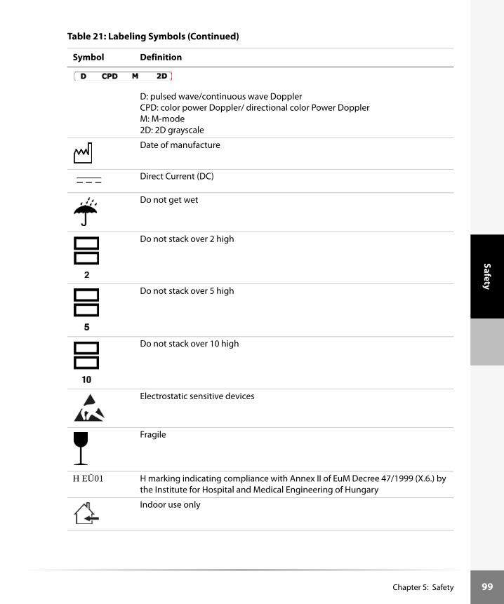
Safety
D: pulsed wave/continuous wave DopplerCPD: color power Doppler/ directional color Power DopplerM: M-mode2D: 2D grayscale
Date of manufacture
Direct Current (DC)
Do not get wet
Do not stack over 2 high
Do not stack over 5 high
Do not stack over 10 high
Electrostatic sensitive devices
Fragile
H EÜ01 H marking indicating compliance with Annex II of EuM Decree 47/1999 (X.6.) by the Institute for Hospital and Medical Engineering of Hungary
Indoor use only
Table 21: Labeling Symbols (Continued)
Symbol Definition
Chapter 5: Safety 99

100
Safe
ty
Non-ionizing radiation
Paper recycle
Serial number type of control number
Storage temperature conditions
Submersible. Protected against the effects of temporary immersion.
Type BF patient applied part (B = body, F = floating applied part)
Type CF patient
Underwriter’s Laboratories labeling
User Guide (1)Power supply (2)Battery (3)Ultrasound gel (4)
ECG label depicting proper lead placementRA = whiteLL = redLA = black
European Union ECG label depicting proper lead placementR = redF = greenL = yellow
Table 21: Labeling Symbols (Continued)
Symbol Definition
IPX7
Chapter 5: Safety

Troubleshooting
Chapter 6: Troubleshooting and Maintenance
TroubleshootingIf you encounter difficulty with the system, use the information in this chapter to help correct the problem. If the problem is not covered here, call SonoSite technical support at the following numbers or addresses:
Technical support 1-877-657-8118
International technical support: Contact your local representative or call 425-951-1330
Technical support fax: 1-425-951-6700
Technical support e-mail: [email protected]
SonoSite website: www.sonosite.com and select Products & Solutions and then Technical Support
Table 1: Troubleshooting Symptom and Solution
Symptom Solution
System will not power on. Check all power connections.Perform the following sequence: remove DC input connector and battery; wait 10 seconds; connect DC input or install battery; press the power switch.Ensure the battery is charged.
System image quality is poor.
Adjust the LCD screen to improve viewing angle.Adjust the brightness, as necessary, to improve image quality.Adjust the contrast, as necessary, to improve image quality.Adjust the gain.
Zoom does not work. Press Freeze. Zoom does not work when the image is frozen.
No CPD image. Adjust the gain.
No DCPD image. Adjust the gain.
No OB measurement selections.
Select the OB or Gyn exam type.
No cardiac measurement selection.
Select the EC1, EC2, EC3, or Che exam type.
Chapter 6: Troubleshooting and Maintenance 101

102
Trou
bles
hoot
ing
Thermal index is not displayed.
System transducer and imaging mode does not exceed 1.0 TI or MI, thermal index is not required.
Caliper line is not displayed.
Set the caliper line in system setup.
Pictographs do not work. Set pictographs in system setup.
Print does not work. Set the correct printer in system setup.Check the printer connections.Check the printer to ensure that it is turned on and setup properly. See the printer manufacturer’s instructions, if necessary.
VCR does not record. Check the video format setting in system setups, including Print/VCR key settingCheck the VCR connections.Check the VCR to ensure that it is turned on and setup properly. See the VCR manufacturers’ instructions, if necessary.
External monitor does not work.
Check the video format setting in system setup.Check the monitor connections.Check the monitor to ensure that it is turned on and setup properly. See the monitor manufacturers’ instructions, if necessary.
Unexpected labels using the function keys.
Ensure labels have been assigned to the function keys.
Inaccurate fetal age calculation.
Ensure that the patient information, date, and time are set accurately.
System does not recognize the transducer.
Disconnect and reconnect the transducer.
Text cursor does not move when trackball or arrows are selected.
Text cursor is constrained to one line.
A maintenance icon displays on the system screen.
This icon indicates that system maintenance is required, record the number on the C: line in parentheses and call your SonoSite representative.
ALI DICOM system will not read the English character set for date, patient name, and patient identification.
Ensure that the OCR feature is setup properly in System Setup.
Table 1: Troubleshooting Symptom and Solution (Continued)
Symptom Solution
Chapter 6: Troubleshooting and Maintenance

Troubleshooting
MaintenanceUse these recommendations when cleaning or disinfecting your ultrasound system, transducers, and accessories. This chapter is intended to assist in effective cleaning and disinfection. It is also intended to protect the system and transducers against damage during cleaning or disinfection. Use the cleaning recommendations in the peripheral manufacturer’s instructions when cleaning or disinfecting your peripherals.For more information about cleaning or disinfection solutions or ultrasound gels used with the transducer, call SonoSite or your local representative. For information about a specific product, call the product manufacturer.
Recommended DisinfectantSee the Table 2, “Disinfectants Compatible with SonoSite System and Transducers” on page 109.
SafetyPlease observe the following warnings and cautions when using cleaners, disinfectants, and gels. More specific warnings and cautions are included in the product literature and in the procedures later in this chapter.
Warning: The level of disinfection required for a device is dictated by the type of tissue it will contact during use. Ensure the disinfectant type is appropriate for the type of transducer and application. For information, see the disinfectant label instructions and the recommendations of the Association for Professionals in Infection Control and Epidemiology (APIC) and FDA.
Most transducers cannot be sterilized. When sterility is required, use a sterile transducer cover.
The use of sterile transducer covers and sterile coupling gel is recommended for clinical applications of all intracavitary transducers. Do not apply the transducer cover and gel until you are ready to perform the procedure.
To avoid serious injury or death, transducers that contact brain tissue (e.g., intra-operative neurological, neurosurgical) should always be used with a pyrogen-free sheath because the disinfectant residue left on the transducer is neuro-toxic.Note: If the transducer is used on a patient with Creutzfeld-Jacob Disease and the sheath breaks, the transducer cannot be adequately disinfected by typical procedures and may need to be destroyed.
Chapter 6: Troubleshooting and Maintenance 103

104
Trou
bles
hoot
ing
Cleaning and Disinfecting the Ultrasound SystemThe exterior surface of the ultrasound system and the accessories can be cleaned and disinfected using a recommended cleaner or disinfectant.To clean the LCD video monitor, dampen a soft, cotton cloth with an ammonia-based window cleaner, and wipe the LCD video monitor clean.
Caution: Do not allow disinfectant to contact metal surfaces. Use a soft cloth lightly dampened in a mild soap or compatible cleaning solution to remove any disinfectant that remains on metal surfaces.
Repeated, long-term exposure to coupling gel can damage transducers.
Some transducer sheaths contain natural rubber latex and talc, which can cause allergic reactions in some individuals. Refer to 21 CFR 801.437, User labeling for devices that contain natural rubber.
Warning: To avoid electrical shock, before cleaning, disconnect the system from the power supply.
Always use protective eyewear and gloves when cleaning and disinfecting systems.
If a pre-mixed disinfection solution is used, observe the solution expiration date, and ensure that the date has not passed.
The level of disinfection required for a product is dictated by the type of tissue it contacts during use. Ensure the solution strength and duration of contact are appropriate for the clinical application of the transducer. For information, see the disinfectant label instructions and the recommendations of the Association for Professionals in Infection Control and Epidemiology (APIC) and FDA.
Caution: Do not spray cleaners or disinfectant directly on the system surfaces. Doing so may cause solution to leak into the system, damaging the system and voiding the warranty.
Do not use strong solvents such as thinner or benzene, or abrasive cleansers, since these will damage the exterior surfaces.
Use only recommended cleaners or disinfectants on system surfaces. Immersion-type disinfectants are not tested for use on system surfaces.
When you clean the system, ensure the solution does not get inside the system keys, the display connections, the transducer receptacle, or the battery compartment.
Do not scratch the LCD video monitor.
Chapter 6: Troubleshooting and Maintenance

Troubleshooting
To clean and disinfect the system surfaces:1 Turn off the system. 2 Disconnect the system from the power adapter.3 Clean the exterior surfaces using a soft cloth lightly dampened in a mild soap or detergent
cleaning solution to remove any particulate matter or body fluids.4 Mix the disinfectant solution compatible with the system, following disinfectant label
instructions for solution strengths and disinfectant contact duration.5 Wipe surfaces with the disinfectant solution.6 Air dry or towel dry with a clean cloth.
Cleaning and Disinfecting TransducersTo disinfect the transducers, use the immersion method or a wipe method. Immersible transducers can be disinfected only if the product labeling of the compatible disinfectant you are using indicates it can be used with an immersion method.
Warning: To avoid electrical shock, before cleaning, disconnect the transducer from the system.
To avoid injury, always use protective eyewear and gloves when cleaning and disinfecting transducers.
To avoid infection, if a pre-mixed solution is used, observe the solution expiration date, and ensure that the date has not passed.
To avoid infection, the level of disinfection required for a transducer is dictated by the type of tissue it contacts during use. Ensure the solution strength and duration of contact are appropriate for the equipment. For information, see the disinfectant label instructions and the recommendations of the Association for Professionals in Infection Control and Epidemiology (APIC) and FDA.
To avoid serious injury or death, transducers that contact brain tissue (e.g., intra-operative neurological, neurosurgical) should always be used with a pyrogen-free sheath because the disinfectant residue left on the transducer is neuro-toxic.Note: If the transducer is used on a patient with Creutzfeld-Jacob Disease and the sheath breaks, the transducer cannot be adequately disinfected by typical procedures and may need to be destroyed.
Caution: Transducers must be cleaned after every use. Cleaning transducers is necessary prior to effective disinfection. Ensure you follow the manufacturer's instructions when using disinfectants.
Do not use a surgeon's brush when cleaning transducers. Even the use of soft brushes can damage a transducer. Use a soft cloth.
Chapter 6: Troubleshooting and Maintenance 105

106
Trou
bles
hoot
ing
To clean and disinfect a transducer using the wipe method:1 Disconnect the transducer from the system.2 Remove any transducer sheath.3 Clean the surface using a soft cloth lightly dampened in a mild soap or detergent cleaning
solution to remove any particulate matter or body fluids.Apply the solution to the cloth rather than the surface.
4 Rinse with water or wipe with water-dampened cloth, then wipe with a dry cloth.5 Mix the disinfectant solution compatible with the transducer, following disinfectant label
instructions for solution strengths and disinfectant contact duration.6 Wipe surfaces with the disinfectant solution.7 Air dry or towel dry with a clean cloth.8 Examine the transducer and cable for damage such as cracks, splitting, or fluid leaks.
If damage is evident, discontinue use of the transducer, and contact SonoSite or your local representative.
To clean and disinfect a transducer using the immersion method:1 Disconnect the transducer from the system.2 Remove any transducer sheath.3 Clean the surface using a soft cloth lightly dampened in a mild soap or compatible cleaning
solution to remove any particulate matter or body fluids.Apply the solution to the cloth rather than the surface.
4 Rinse with water or a wipe with water-dampened cloth, then wipe with a dry cloth.5 Mix the disinfectant solution compatible with the transducer, following disinfectant label
instructions for solution strengths and disinfectant contact duration.6 Immerse the transducer into the disinfection solution not more than 12-18 inches (31-46 cm)
from the point where the cable enters the transducer.7 Follow the instructions on the disinfectant label for the duration of the transducer immersion.8 Using the instructions on the disinfectant label, rinse to the point of the previous immersion,
and then air dry or towel dry with a clean cloth.9 Examine the transducer and cable for damage such as cracks, splitting, or fluid leaks. If damage
is evident, discontinue use of the transducer, and contact SonoSite or your local representative.
Using a non-recommended cleaning or disinfection solution, incorrect solution strength, or immersing a transducer deeper or for a longer period of time than recommended can damage or discolor the transducer and void the transducer warranty.
Do not allow cleaning solution or disinfectant into the transducer receptacle.
Do not allow disinfectant to contact metal surfaces. Use a soft cloth lightly dampened in a mild soap or compatible cleaning solution to remove any disinfectant that remains on metal surfaces.
Chapter 6: Troubleshooting and Maintenance

Troubleshooting
Cleaning and Disinfecting the ECG CablesTo disinfect your ECG cable, you can use a wipe method. The compatible disinfectants are bleach (sodium hypochlorite) and Cidex. Bleach is EPA registered and Cidex has FDA 510(k) clearance and is EPA registered.
For more information about disinfectant compatibility, see Table 2, “Disinfectants Compatible with SonoSite System and Transducers” on page 109.
Sterilizing TransducersSome SonoSite transducers can be sterilized using a liquid sterilant. See “Disinfectants Compatible with SonoSite System and Transducers” on page 109.
Cleaning and Disinfecting Transducer CablesThe transducer cable can be disinfected using a recommended wipe or immersion disinfectant. Before disinfecting, orient the cable to ensure that the transducer and system do not get immersed.
To clean and disinfect the transducer cable using the wipe method:1 Disconnect the transducer from the system.2 Remove any transducer sheath.3 Clean the surface using a soft cloth lightly dampened in a mild soap or detergent cleaning
solution to remove any particulate matter or body fluids.Apply the solution to the cloth rather than the surface.
4 Rinse with water or wipe with water-dampened cloth, then wipe with a dry cloth.5 Mix the disinfectant solution compatible with the transducer cable, following disinfectant label
instructions for solution strengths and disinfectant contact duration.6 Wipe surfaces with the disinfectant solution.7 Air dry or towel dry with a clean cloth.8 Examine the transducer and cable for damage such as cracks, splitting, or fluid leaks.
If damage is evident, discontinue use of the transducer, and contact SonoSite or your local representative.
Warning: Do not sterilize the ECG cable.
Warning: To avoid infection, if a pre-mix solution is used, observe the solution expiration date, and ensure that the date has not passed.
Caution: Attempting to disinfect a transducer cable using a method other than the one included here can damage the transducer and void the warranty.
Chapter 6: Troubleshooting and Maintenance 107

108
Trou
bles
hoot
ing
To clean and disinfect the transducer cable using the immersion method:1 Disconnect the transducer from the system.2 Remove any transducer sheath.3 Clean the transducer cable using a soft cloth lightly dampened in a mild soap or compatible
cleaning solution to remove any particulate matter or body fluids.Apply the solution to the cloth rather than the surface.
4 Rinse with water or a wipe with water-dampened cloth, then wipe with a dry cloth.5 Mix the disinfectant solution compatible with the transducer cable, following disinfectant label
instructions for solution strengths and disinfectant contact duration.6 Immerse the transducer cable into the disinfection solution.7 Follow the instructions on the disinfectant label for the duration of the transducer cable
immersion.8 Using the instructions on the disinfectant label, rinse the transducer cable, and then air dry or
towel dry with a clean cloth.9 Examine the transducer and cable for damage such as cracks, splitting, or fluid leaks. If damage
is evident, discontinue use of the transducer, and contact SonoSite or your local representative.
Chapter 6: Troubleshooting and Maintenance

Chapter 6: Troubleshooting and M
aintenance109
HST L25 C8 SystemSurfaces
N U U U
U U U N
U U U N
N U U U
U U U N
T, C U U N
N U U U
T U U N
T U U N
N U U N
U U U U
N U U N
N U U N
N U U U
N U U U
U U T, C A
U U T, C A
Troubleshooting
Table 2: Disinfectants Compatible with SonoSite System and Transducers
Disinfection and Cleaning Solutions
Country of Origin Type Active Ingredient C60/
L38C15/C11 ICT
105 Spray USA Spray Quat. Ammonia T, C U N
AbcoCide (4) USA Liquid Gluteraldehyde T U T
AbcoCide 28 (4) USA Liquid Gluteraldehyde T U T
Aidal Plus Australia Liquid Gluteraldehyde U U U
Alkacide France Liquid Gluteraldehyde T, C U T, C
Alkalingettes (3) France Liquid Alkylamine, Isopropanol
T, C U N
Alkaspray GSA (3) France Spray Isopropyl Alcohol U U U
Alkazyme France Liquid Quat. Ammonia T, C U N
Ampholysine Basique (3)
France Liquid Biguanide/Quat. Ammonia
T U N
Ampholysine plus France Liquid Quat. Ammonia T, C U N
Amphosept BV France Liquid Quat. Ammonia U U U
Amphospray 41 (3) France Spray Ethanol T, C U N
Amphyl (4) USA Liquid O-phenylphenol T U N
Aniosyme P.L.A. France Liquid Quat. Ammonia U U U
Anioxyde 1000 France Liquid Hydrogen PeroxidePeracetic Acid
U U U
Ascend (4) USA Liquid Quat Ammonia U U U
Asepti-HB (4) USA Liquid Quat Ammonia U U U

110Chapter 6: Troubleshooting and M
aintenance
Troubleshooting
N U N
U T, C U
U T, C A
N U N
N U N
U T, C A
U U N
N T, C A
U U N
U U N
T, C T, C N
N N N
U U A
U U U
U U U
U U N
L25 C8 SystemSurfaces
Asepti-Steryl 14 or 28 (4)
USA Liquid Gluteraldehyde T, C N T, C T, C
Asepti-Steryl USA Spray Ethanol U U U U
Asepti-Wipes (4) USA Wipes Propanol (Isopropyl Alcohol)
U U U U
Aseptosol Germany Liquid Gluteraldehyde N N N N
Autoclave (Steam) System Steam/Heat N N N N
Bacillocid rasant Germany Liquid Glut./Quat. Ammonia
T, C T, C N N
Bacillol 25 Germany Liquid Ethanol/Propanol T, C U N N
Bacillol Plus (3) Germany Spray Propanol/Glut. T, C N N N
Bactilysine France Liquid Quat. Ammonia T, C U N N
Baktobod Germany Liquid Glut. Quat. Ammonia
T, C U N N
Banicide (4) USA Liquid Gluteraldehyde T, C T, C T, C U
Betadine USA Liquid Providone-Iodine N N N N
Biotensid Germany Spray 2-Propanol N N N N
Biospray France Spray Ethanol/Aldehyde U U U N
Bioxal M (3) France Liquid Hydrogen Peroxide, Acetic Acid
U U U N
Bleach (4) USA Liquid NaCl Hypochlorite T, C U N N
Table 2: Disinfectants Compatible with SonoSite System and Transducers (Continued)
Disinfection and Cleaning Solutions
Country of Origin Type Active Ingredient C60/
L38C15/C11 ICT HST

Chapter 6: Troubleshooting and M
aintenance111
N U U N
U U U N
N T, C T, C N
N U U N
N U U A
N U U N
T, C T, C T, C A
T, C T, C T, C A
N U U N
T T, C U A
N U U U
U U U N
N U U U
N T, C T, C N
N T, C T, C A
N U U A
U N N N
HST L25 C8 SystemSurfaces
Troubleshooting
Bodedex France Liquid Quat. Ammonia T, C U N
Burnishine (4) USA Liquid Gluteraldehyde T, C U T, C
Cavicide (4) USA Liquid Isopropyl T, C T, C N
Cetavlon France Liquid Cetrimide T, C U N
Chlorispray France Spray Gluteraldehyde T, C U N
Cidalkan (3) France Liquid Alkylamine, isopropanol
N N N
Cidex (2) (4) (5) USA Liquid Gluteraldehyde T, C T, C T, C
Cidex OPA (2) (3) (4) (5)
USA Liquid ortho-phthaldehyde T, C T, C T, C
Cidex PA (3) (4) USA Liquid Hydrogen Peroxide/Peracetic Acid
N N N
Cidex Plus (2) (4) (5) USA Liquid Gluteraldehyde T, C T, C T, C
Cidezyme USA Cleaner Ethylene Glycol U U U
Coldspor (4) USA Liquid Gluteraldehyde T, C U T, C
Coldspor Spray USA Spray Gluteraldehyde T, C U N
Control III (4) USA Liquid Quat. Ammonia T, C T, C N
Coverage Spray (4) USA Spray Quat. Ammonia T, C U N
Cutasept F Germany Spray 2-Propanol T U N
Dentured Alcohol USA Liquid Ethanol N N N
Table 2: Disinfectants Compatible with SonoSite System and Transducers (Continued)
Disinfection and Cleaning Solutions
Country of Origin Type Active Ingredient C60/
L38C15/C11 ICT

112Chapter 6: Troubleshooting and M
aintenance
Troubleshooting
U T, C U
T, C T, C A
T, C T, C N
U U N
U U N
U U N
T, C T, C A
N T, C N
T, C T, C A
U U U
U U U
U U N
N U N
U U N
U U N
U U N
U U N
T, C T, C N
L25 C8 SystemSurfaces
Dialdehyde (4) USA Liquid Gluteraldehyde U U U U
Dismonzon pur (3) Germany Liquid Hexahydrate T, C T, C N N
Dispatch (4) USA Spray NaCl Hypochlorite T, C T, C N N
End-Bac II USA Liquid Quat. Ammonia N N N N
Endo FC France Liquid Gluteraldehyde T, C U T, C T, C
Endosporine (3) France Liquid Gluteraldehyde T, C U T, C U
Endozime AW Plus (3) France Liquid Propanol T, C T, C U N
Envirocide (4) USA Liquid Isopropyl T, C T, C N N
Enzol USA Cleaner Ethylene Glycol T, C T, C T, C N
Enzy-Clean USA Cleaner Amylase/Protease Complex
U U U T, C
Epizyme Rapid Australia Cleaner Citric Acid U U U T, C
Esculase 388 France Liquid Quat. Ammonia T, C U N N
Ethylene Oxide (EtO) (4)
System Ethylene Oxide N N N N
Expose USA Liquid Isopropyl T, C N N N
Foam Insurance USA Spray n-Alkyl T, C U N N
Formac USA Liquid Gluteraldehyde T, C U T, C U
Gercid 90 France Liquid Quat. Ammonia T, C U N N
Gigasept AF (3) Germany Liquid Quat. Ammonia T, C T, C N T, C
Table 2: Disinfectants Compatible with SonoSite System and Transducers (Continued)
Disinfection and Cleaning Solutions
Country of Origin Type Active Ingredient C60/
L38C15/C11 ICT HST

Chapter 6: Troubleshooting and M
aintenance113
N T, C T, C N
U U U N
U U T, C U
N U U N
N U U U
N T, C T, C N
N T, C T, C A
U U T, C U
N U U U
N U U A
N U U U
N U U N
T U U N
N U U U
N U U U
T U U U
N U U U
T N T, C A
HST L25 C8 SystemSurfaces
Troubleshooting
Gigasept FF (3) Germany Liquid Bersteinsaure T, C T, C N
Glutacide USA Liquid Gluteraldehyde T, C U T, C
Gluteraldehyde SDS USA Liquid Gluteraldehyde U U U
Helipur H+N (3) Germany Liquid Gluteraldehyde/Propanol
N N N
Hexanios France Liquid Polyhexanide/Quat. Ammonia
U U U
Hi Tor Plus (4) USA Liquid Chloride T, C T, C N
Hibiclens USA Cleaner Chlorhexidine T, C U N
Hydrogen Peroxide USA Liquid Hydrogen Peroxide U U U
Incides Germany Wipe Alcohol N N N
Incidine Germany Spray Aldehydes T U N
Incidur Germany Liquid Gluteraldehyde U U U
Incidur Spray Germany Spray Ethanol N N N
Instruzyme France Liquid Quat. Ammonia T, C U N
Kawason Australia U U U
Kleen-aseptic b (4) USA Spray Isopropanol T, C U N
Klenzyme USA Cleaner Proteolytic Enzymes U U U
Kodan Germany Spray Propanol/Alcohol U U U
Kohrsolin ff Germany Liquid Gluteraldehyde N N N
Table 2: Disinfectants Compatible with SonoSite System and Transducers (Continued)
Disinfection and Cleaning Solutions
Country of Origin Type Active Ingredient C60/
L38C15/C11 ICT

114Chapter 6: Troubleshooting and M
aintenance
Troubleshooting
U U U
U T, C U
T, C T, C A
U U N
N N A
U U U
U U U
U U N
N T, C N
U U N
N U N
N N N
T, C T, C N
T, C T, C N
U U U
U U N
L25 C8 SystemSurfaces
Kohrsolin iD Germany Liquid Gluteraldehyde U U U T
Korsolex (3) Germany Liquid Gluteraldehyde U U U T, C
Korsolex basic (3) Germany Liquid Gluteraldehyde N N N T, C
Korsolex Consentrate (3)
Germany Liquid Gluteraldehyde N N N N
Korsolex FF (3) Germany Liquid Gluteraldehyde N N N U
Korsolex pret a l’emploi
Germany Liquid Gluteraldehyde U U U T, C
Kutasept Germany U U U N
Linget’anios France Towelette Quat. Ammonia T, C U N N
LpHse (4) USA Liquid O-phenylphenol T, C N N N
Lysertol V Neu (3) Germany Liquid Gluteraldehyde, Formaldahyde, Quat. Ammonium chloride
T, C U N T
Lysol IC (4) USA Liquid O-phenylphenol T, C N N N
Lysol Spray USA Spray Ethanol N N N U
Madacide (4) USA Liquid Isopropanol T, C T, C N N
Matar (4) USA Liquid O-phenylphenol T, C T, C N N
Medi-Swab Sweden Wipe Isopropyl/Alcohol U U U N
Medside Medallion USA Liquid Quat. Ammonia T U N N
Table 2: Disinfectants Compatible with SonoSite System and Transducers (Continued)
Disinfection and Cleaning Solutions
Country of Origin Type Active Ingredient C60/
L38C15/C11 ICT HST

Chapter 6: Troubleshooting and M
aintenance115
T U U N
T U T, C N
U T, C U N
T U U N
U U U U
U T, C T, C A
T T, C T, C A
N N T, C A
N U U N
N U U N
N T, C T, C N
N U U N
U U U N
U U U N
U U U N
N U U N
HST L25 C8 SystemSurfaces
Troubleshooting
MetriCide 14 (2) (4) (5)
USA Liquid Gluteraldehyde T T T
MetriCide 28 (2) (4) (5)
USA Liquid Gluteraldehyde T, C N T, C
MetriCide Plus (4) (5) USA Liquid Gluteraldehyde T, C T, C T, C
Metriguard (4) USA Liquid Ammonium Chloride
T, C U N
MetriSpray (3) (4) USA Spray Gluteraldehyde T, C U N
MetriZyme USA Cleaner Propylene Glycol T, C T, C N
Mikrobak forte (3) Germany Liquid Ammonium Chloride
T, C T, C N
Mikrozid Tissues (3) Germany Wipe Ethanol/Propanol N N N
Milton Australia Liquid Sodium Hypochlorite
T, C U N
New Ger (3) Spain Liquid n-Duopropenide T, C U N
Nuclean France Spray Alcohol/Biguanide T, C U N
Omega (4) USA Liquid Isopropyl T, C U N
Omnicide 14NS (2) (4)
USA Liquid Gluteraldehyde T U T
Omnicide 28 (2) (4) USA Liquid Gluteraldehyde T, C U T, C
Ovation (4) USA Liquid O-phenylphenol T, C U N
Peract 20 (1) (2) (3) (5) USA Liquid Hydrogen Peroxide N N N
Table 2: Disinfectants Compatible with SonoSite System and Transducers (Continued)
Disinfection and Cleaning Solutions
Country of Origin Type Active Ingredient C60/
L38C15/C11 ICT

116Chapter 6: Troubleshooting and M
aintenance
Troubleshooting
U U N
U U U
U U N
U U U
U U U
U U U
U U N
T, C T, C A
U U N
U U N
U U N
U U N
L25 C8 SystemSurfaces
Phagocide D (3) France Liquid Gluteraldehyde T, C U T, C T, C
Phagolase ND NFLE (3)
France Cleaner Quaternary Ammonium, Alkylamine, Enzyme proteolytique
T, C U T, C T, C
Phagolase pH Basique
France Liquid Gluteraldehyde T, C U T, C T, C
Phagolingette D 120 (3)
France Towelette Alcohol, Biguanide, Quaternary Ammonium
N N N N
Phagosept Spray (3) France Spray Alcohol, Biguanide, Quaternary Ammonium
N N N N
Phagozyme ND (3) France Liquid Quaternary Ammonium Enzymes
U U U T, C
PowerQuat USA Liquid Quat. Ammonia T, C U N N
Precise (4) USA Spray O-phenylphenol T, C U N N
Presept USA Liquid NaCl Dichlorite T, C U N N
Presept Canada Liquid Gluteraldehyde T, C U T, C U
Pro-Cide (4) USA Liquid Gluteraldehyde T, C U T, C U
Pro-Cide 14NS (2) (4) (5)
USA Liquid Gluteraldehyde T, C U T, C U
Table 2: Disinfectants Compatible with SonoSite System and Transducers (Continued)
Disinfection and Cleaning Solutions
Country of Origin Type Active Ingredient C60/
L38C15/C11 ICT HST

Chapter 6: Troubleshooting and M
aintenance117
N U U N
N U U N
U U U N
N U U N
N T, C T, C A
N U U N
U N T, C U
T, C U U N
N U U A
U T, C T, C U
U U U N
U U U N
T U U U
T, C U U N
T, C U U N
T U U N
N U U N
U U U N
N U U N
HST L25 C8 SystemSurfaces
Troubleshooting
Prontocid N (3) Germany Liquid Formaldahyde/Gluteraldehyde
N N N
Pyobactene France Liquid Aldehydes T, C U N
Pyosynthene EA 20 France Liquid Formaldahyde T, C U N
Rivascop France Liquid Quat. Ammonia T, C U N
Ruthless USA Spray Quat. Ammonia N N N
Sagrosept Germany Liquid Propanol N N N
Sagrosept Germany Wipe Proponal T, C N N
Salvanios pH 10 France Liquid Quat. Ammonia T, C U N
Sani-Cloth (4) USA Wipe Quat. Ammonia T, C U N
Sani-Cloth Plus (4) USA Wipe Quat. Ammonia U U U
SDS 14NS (4) USA Liquid Gluteraldehyde T, C U T, C
SDS 28 (4) USA Liquid Gluteraldehyde T, C U T, C
Seku Extra Germany Liquid Gluteraldehyde U U U
Sekucid France Liquid Gluteraldehyde T, C U T, C
Sekucid N (3) France Liquid Gluteraldehyde T, C U T, C
Sekulyse France Liquid Biguanide T, C U N
Sekusept Extra Germany Liquid Glyoxal/Glut. T, C T, C N
Sekusept Extra N Germany Liquid Gluteraldehyde T, C T, C T, C
Sekusept forte Germany Liquid Formaldahyde T, C T, C N
Table 2: Disinfectants Compatible with SonoSite System and Transducers (Continued)
Disinfection and Cleaning Solutions
Country of Origin Type Active Ingredient C60/
L38C15/C11 ICT

118Chapter 6: Troubleshooting and M
aintenance
Troubleshooting
U U U
U U N
U U N
N T, C N
U U A
U U N
U U U
N T, C U
N T, C A
U U U
U U N
N T, C N
T, C T, C U
N U N
U U A
U U U
L25 C8 SystemSurfaces
Sekusept forte S Germany Liquid Formaldehyde/Glyoxal/Gluteraldehyde/Quat. Ammonia
U U U N
Sekusept Plus Germany Liquid Glucoprotamin T, C T, C N N
Sekusept Pulver Germany Liquid Natriumperborat T, C U N N
Sklar (4) USA Liquid Isopropanol T, C T, C N N
Softasept N Germany Spray Ethanol N N N N
Sporadyne France Liquid Didecyldimethyl T, C U N T
Sporadyne pret a l’empoi (3)
France Liquid Gluteraldehyde U U U T
Sporicidin (2) (4) (5) USA Liquid Phenol T, C T, C N N
Sporicidin (4) USA Wipes Phenol T, C T, C N N
Sporicidin Sterilant (2)
USA Liquid Phenol, Sodium Phenate, Glute.
U U U T, C
Sporox II (2) (4) USA Liquid Hydrogen Peroxide T, C U T, C T, C
Staphene (4) USA Spray Ethanol T, C N N N
Steranios France Liquid Gluteraldehyde U U U N
STERIS (2) (4) USA Liquid Peracetic Acid N N N N
Surfaces Hautes (3) France Spray Quat. Ammonia T, C U N N
Surg L Kleen USA Liquid U U U N
Table 2: Disinfectants Compatible with SonoSite System and Transducers (Continued)
Disinfection and Cleaning Solutions
Country of Origin Type Active Ingredient C60/
L38C15/C11 ICT HST

Chapter 6: Troubleshooting and M
aintenance119
N N T, C N
N N U N
N T, C T, C N
N U U N
N U U A
N N T, C N
N T, C U N
U U U U
N N T, C A
N U U U
T U U N
N N N N
U U U N
N U U N
N U U U
N U U U
N U U U
HST L25 C8 SystemSurfaces
Troubleshooting
T-Spray (3) USA Spray Quat. Ammonia T, C U N
T-Spray II (3) USA Spray Alkyl/Chloride T U N
TBQ (4) USA Liquid Alkyl T, C T, C N
Theracide USA Liquid Quat. Ammonia T, C T, C N
Theracide USA Wipe Quat. Ammonia T, C T, C N
Theracide Plus (4) USA Liquid Quat. Ammonia T, C U N
Tor (4) USA Liquid Quat. Ammonia T, C T, C N
Tor Spray USA Spray Butoxyethanol Alkane
U U U
Transeptic USA Cleaner Alcohol T N T
Ultra Swipes USA Wipe Ethanol T, C U N
Vaposeptol Germany Spray Biguanide T, C U N
Vesphene II (4) USA Liquid Sodium/o-Phenylphenate
T, C T, C N
Vespore (4) USA Liquid Gluteraldehyde T, C U T, C
Virex (4) USA Liquid Quat. Ammonia T, C U N
Virkon Australia Liquid Potassium Monopersulfate
U U U
VP 483 Germany Liquid U U U
VP 483/2H Germany Liquid U U U
Table 2: Disinfectants Compatible with SonoSite System and Transducers (Continued)
Disinfection and Cleaning Solutions
Country of Origin Type Active Ingredient C60/
L38C15/C11 ICT

120Chapter 6: Troubleshooting and M
aintenance
Troubleshooting
T, C T, C N
N T, C N
T, C T, C N
U U U
U U U
L25 C8 SystemSurfaces
Wavicide -01 (2) (4) (5)
USA Liquid Gluteraldehyde T, C T, C T, C N
Wavicide -06 (4) USA Liquid Gluteraldehyde T, C N T, C N
Wex-Cide (4) USA Liquid O-phenylphenol T, C T, C N N
Wipe Out USA Liquid Phenol/Gluteraldehyde
U U U N
Ytdesinfektion Plus Sweden Liquid Isopropanol U U U N
(1) Compatible but no EPA Registration(2) Has FDA 510(k)(3) Has CE Mark(4) EPA Registered(5) FDA 510(k) cleared liquid sterilant or high level disinfectant
A = Acceptable for useN = No (do not use)T = Transducer onlyT, C = Transducer and CableU = Untested (do not use)
Table 2: Disinfectants Compatible with SonoSite System and Transducers (Continued)
Disinfection and Cleaning Solutions
Country of Origin Type Active Ingredient C60/
L38C15/C11 ICT HST

Troubleshooting
Chapter 6: Troubleshooting and Maintenance 121

122
Trou
bles
hoot
ing
Chapter 6: Troubleshooting and Maintenance

References
Chapter 7: References
This section includes information about clinical measurements that can be made with the system, the accuracy of each measurement, and factors affecting measurement accuracy. Also included are clinical references for the system calculations.
Measurement Accuracy
Display SizeThe precision with which a caliper can be placed in an image can be improved by making sure the area of interest fills as much of the screen as possible.In 2D imaging, distance and area measurements are improved by minimizing the display depth and using the zoom function where possible.
Caliper PlacementWhen making a measurement, accurate placement of the caliper is essential.To improve caliper placement precision: adjust the display for maximum sharpness; use leading edges (closest to the transducer) or borders for start and stop points; and maintain a consistent transducer orientation for each type of measurement.When the calipers are positioned farther apart, they get larger. When the calipers are moved closer together, they get smaller. The caliper line disappears as the calipers get closer together.
2D Measurements and CalculationsThe measurements provided by the system do not define a specific physiological or anatomical parameter. Rather, what is provided is a measurement of a physical property such as distance for evaluation by the clinician. Measurement and analysis performance includes the accuracy of the caliper measurements and the accuracy of algorithms used to analyze the measurements. The accuracy values require that you can place the calipers over one pixel. The values do not include acoustic anomalies of the body.The 2D linear distance measurement results are displayed in centimeters with one place past the decimal point, if the measurement is ten or greater; two places past the decimal point, if the measurement is less than ten. The 2D circumference is displayed in centimeters with one place past the decimal point and two places past the decimal point when displaying less than 10 centimeters.The linear distance measurement components have the accuracy and range shown in the following tables:
Chapter 7: References 123

124
Refe
renc
es
Table 1: 2D Measurement Accuracy and Range Table
2D Measure Accuracy and Range
System Tolerancea Accuracy ByTest Methodb Range (cm)
Axial Distance < ±2% plus 1% of full scale Acquisition Phantom 0.1-30 cm
Lateral Distance < ±2% plus 1% of full scale Acquisition Phantom 0.1-35 cm
Diagonal Distance
< ±2% plus 1% of full scale Acquisition Phantom 0.1-30 cm
Areac < ±4% plus 1% of full scale Acquisition Phantom 0.1-1000 cm2
Circumferenced < ±3% plus 1% of full scale Acquisition Phantom 0.1-110 cm
a. Full scale for distance implies the maximum depth of the image.b. An RMI 413a model phantom with 0.7 dB/cm-MHz attenuation was used.c. The area accuracy is defined using the following equation:
% tolerance = ((1 + lateral error) * (1 + axial error) – 1) * 100 + 0.5%.d. The circumference accuracy is defined as the greater of the lateral or axial accuracy and by the following
equation: % tolerance = ((maximum of 2 errors) * 100) + 0.5%.
Table 2: M-mode Measurement and Calculation Accuracy and Range
M-mode Measurement Accuracy and Range
System Tolerance Accuracy By Test Method Range
Distance < +/- 2% plus 1% of full scalea
Acquisition Phantomb 0.01-25 cm
Time < +/- 2% plus 1% of full scalec
Acquisition Phantomd 0.01-9.0 sec
Heart Rate < +/- 2% plus (Full Scalec * Heart Rate/100) %
Acquisition Phantomd 20-300 bpm
a. Full scale for distance implies the maximum depth of the image.b. An RMI 413a model phantom with 0.7 dB/cm-MHz attenuation was used.c. Full scale for time implies the total time displayed on the scrolling graphic image.d. SonoSite special test equipment was used.
Chapter 7: References

References
Sources of Measurement ErrorsIn general, two types of errors can be introduced into the measurement: acquisition error and algorithmic error.
Acquisition ErrorAcquisition error includes errors introduced by the ultrasound system electronics relating to signal acquisition, signal conversion, and signal processing for display. Additionally, computational and display errors are introduced by the generation of the pixel scale factor, application of that factor to the caliper positions on the screen, and the measurement display.
Algorithmic ErrorAlgorithmic error is the error introduced by measurements, which are input to higher order calculations. This error is associated with floating-point versus integer-type math, which is subject to errors introduced by rounding versus truncating results for display of a given level of significant digit in the calculation.
Terminology and Measurement PublicationsTerminology and measurements comply with AIUM published standards.
Table 3: PW and CW Doppler Mode Measurement and Calculation Accuracy and Range Table
Doppler Mode Measurement Accuracy and Range
System Tolerance Accuracy By Test Methoda Range
Velocity cursor < +/- 2% plus 1% of full scaleb
Acquisition Phantom 0.01 cm/sec-20 m/sec
Frequency cursor
< +/- 2% plus 1% of full scaleb
Acquisition Phantom 100Hz-62.5 kHz
Time < +/- 2% plus 1% of full scalec
Acquisition Phantom 0.01-9.0 sec
a. SonoSite special test equipment was used.b. Full scale for frequency or velocity implies the maximum frequency or velocity magnitude, positive or
negative, displayed on the scrolling graphic image.c. Full scale for time implies the total time displayed on the scrolling graphic image.
Chapter 7: References 125

126
Refe
renc
es
Cardiac References
Left Atrium/Aorta (LA/Ao)Feigenbaum, H. Echocardiography. Philadelphia: Lea and Febiger, (1994), 206, Figure 4-49.
Acceleration (ACC) in cm/s2Zwiebel, W.J. Introduction to Vascular Ultrasonography. 4th ed., W.B. Saunders Company, (2000), 52.ACC = abs (delta velocity/delta time)
Acceleration Time (AT) in msecOh, J.K., J.B. Seward, A.J. Tajik. The Echo Manual. 2nd ed., Lippincott, Williams, and Wilkins, (1999), 219.See Figure 1, “Trace Calculations of the Doppler Wave Form” on page 48.
Aortic Valve Area (AVA) by Continuity Equation in cm2
Reynolds, Terry. The Echocardiographer’s Pocket Reference. 2nd ed., School of Cardiac Ultrasound, Arizona Heart Institute, (2000), 383, 442.A2 = A1 * V1/V2
where: A2 = Ao valve areaA1 = LVOT area; V1 = LVOT velocity; V2 = Ao valve velocityLVOT – left ventricular outflow tract
AVA (PV LVOT / PV AO) * CSA LVOT
AVA (VTI LVOT / VTIAO) * CSA LVOT
Cardiac Output (CO) in l/minOh, J.K., J.B. Seward, A.J. Tajik The Echo Manual. 2nd ed., Lippincott, Williams, and Wilkins, (1999), 59.CO = (SV * HR)/1000where: CO = Cardiac Output
SV = Stroke VolumeHR = Heart Rate
Cross Sectional Area (CSA) in cm2
Reynolds, Terry. The Echocardiographer’s Pocket Reference. 2nd ed., School of Cardiac Ultrasound, Arizona Heart Institute, (2000), 383.CSA = 0.785 * D2
where: D = diameter of the anatomy of interest
Chapter 7: References

References
Delta Pressure: Delta Time (dP:dT) in mmHg/sOtto, C.M. Textbook of Clinical Echocardiography. 2nd ed., W.B. Saunders Company, (2000), 117, 118.32 mmHg/time interval in seconds
E:A ratio in cm/secE:A = velocity E/velocity A
Ejection Fraction (EF), percentOh, J.K., J.B. Seward, A.J. Tajik. The Echo Manual. 2nd ed., Lippincott, Williams, and Wilkins, (1999), 40.EF = ((LVEDV– LVESV)/LVEDV) * 100%where: EF = Ejection Fraction
LVEDV = Left Ventricular End Diastolic VolumeLVESV = Left Ventricular End Systolic Volume
Elapsed Time (ET) in msecET = time between velocity cursors in milliseconds
Heart Rate (HR) in bpmHR = 3 digit value input by user or measured on M-mode and Doppler image in one heart cycle
Interventricular Septum (IVS) Fractional Thickening, percentLaurenceau, J. L., M.C. Malergue. The Essentials of Echocardiography. Le Hague: Martinus Nijhoff, (1981), 71.IVSFT = ((IVSS – IVSD)/IVSD) * 100%where: IVSS = Interventricular Septal Thickness at Systole
IVSD = Interventricular Septal Thickness at Diastole
Left Ventricular End Volumes (Teichholz) in mlTeichholz, L.E., T. Kreulen, M.V. Herman, et. al. “Problems in echocardiographic volume determinations: echocardiographic-angiographic correlations in the presence or absence of asynergy.” American Journal of Cardiology, (1976), 37:7.LVESV = (7.0 * LVDS3)/(2.4 + LVDS)where: LVESV = Left Ventricular End Systolic Volume
LVDS = Left Ventricular Dimension at SystoleLVEDV = (7.0/(2.4 + LVDD)) * LVDD3
where: LVEDV = Left Ventricular End Diastolic VolumeLVDD = Left Ventricular Dimension at Diastole
Chapter 7: References 127

128
Refe
renc
es
Left Ventricular Dimension (LVD) Fractional Shortening, percentOh, J.K., J.B. Seward, A.J. Tajik. The Echo Manual. Boston: Little, Brown and Company, (1994), 43-44.LVDFS = ((LVDD – LVDS)/LVDD) * 100%where: LDD = Left Ventricle Dimension at Diastole
LVDS = Left Ventricle Dimension at Systole
Left Ventricular Posterior Wall Fractional Thickening (LVPWFT), percentLaurenceau, J. L., M.C. Malergue. The Essentials of Echocardiography. Le Hague: Martinus Nijhoff, (1981), 71.LVPWFT = ((LVPWS – LVPWD)/LVPWD) * 100%where: LVPWS = Left Ventricular Posterior Wall Thickness at Systole
LVPWD = Left Ventricular Posterior Wall Thickness at Diastole
Mean Velocity (Vmean) in cm/sVmean = mean velocity
Mitral Valve Area (MVA) in cm2
Reynolds, Terry. The Echocardiographer’s Pocket Reference. 2nd ed., School of Cardiac Ultrasound, Arizona Heart Institute, (2000), 391, 452.MVA = 220/PHTwhere: PHT = pressure half timeNote: 220 is an empirical derived constant and may not accurately predict mitral valve area in mitral prosthetic heart valves. The mitral valve area continuity equation may be utilized in mitral prosthetic heart valves to predict effective orifice area.
Pressure Gradient (PGr) in mmHGOh, J.K., J.B. Seward, A.J. Tajik. The Echo Manual. 2nd ed., Lippincott, Williams, and Wilkins, (1999), 64.4 * (Velocity)2
Peak E Pressure Gradient (E PG)E PG = 4 * PE2
Peak A Pressure Gradient (A PG)A PG = 4 * PA2
Peak Pressure Gradient (PGmax)PGmax = 4 * PV2
Mean Pressure Gradient (PGmean)PGmean = 4 * Vmax2
Chapter 7: References

References
Pressure Half Time (PHT) in msecReynolds, Terry. The Echocardiographer’s Pocket Reference. 2nd ed., School of Cardiac Ultrasound, Arizona Heart Institute, (2000), 391.PHT = DT * 0.29where: DT = deceleration time
Stroke Volume (SV) Doppler in mlOh, J.K., J.B. Seward, A.J. Tajik. The Echo Manual. 2nd ed., Lippincott, Williams, and Wilkins, (1999), 40, 59, 62.
Stroke Volume (SV) 2D and M-mode in mlOh, J.K., J.B. Seward, A.J. Tajik. The Echo Manual. 2nd ed., Boston: Little, Brown and Company, (1994), 44.SV = (LVEDV – LVESV)where: SV = Stroke Volume
LVEDV = End Diastolic VolumeLVEDSV = End Systolic Volume
Velocity Time Integral (VTI) in cmReynolds, Terry. The Echocardiographer’s Pocket Reference. 2nd ed., School of Cardiac Ultrasound, Arizona Heart Institute, (2000), 383.VTI = sum of abs (velocities [n])where: Auto Trace – distance (cm) blood travels with each ejection period. Velocities are
absolute values.
Obstetrical References
Abdominal Circumference (AC)University of Tokyo, Shinozuka, N. FJSUM, et al. “Standard Values of Ultrasonographic Fetal Biometry.” Japanese Journal of Medical Ultrasonics, 23:12 (1996), 885.
Amniotic Fluid Index (AFI)Hadlock, F., et al. “Estimating Fetal Age: Computer-Assisted Analysis of Multiple Fetal Growth Parameters.” Radiology, 152: (1984), 497-501.Hansmann, M., et al. Ultrasound Diagnosis in Obstetrics and Gynecology. New York: Springer-Verlag, (1986), 431.
Warning: The gestational age calculated by your SonoSite system does not match the age in the aforementioned reference at the 20.0 cm and 30.0 cm abdominal circumference (AC) measurements. The implemented algorithm extrapolates the gestational age from the slope of the curve of all table measurements, rather than decreasing the gestational age for a larger AC measurement indicated in the referenced table. This results in the gestational age always increasing with an increase in AC.
Chapter 7: References 129

130
Refe
renc
es
Chitty, Lyn S. et al. “Charts of Fetal Size: 3. Abdominal Measurements.” British Journal of Obstetrics and Gynaecology 101: (February 1994), 131, Appendix: AC-Derived.Jeng AFI EquationJeng, C. J., et al. “Amniotic Fluid Index Measurement with the Four Quadrant Technique During Pregnancy.” The Journal of Reproductive Medicine, 35:7 (July 1990), 674-677.
Anteroposterior Trunk Diameter (APTD)University of Tokyo, Shinozuka, N. FJSUM, et al. “Standard Values of Ultrasonographic Fetal Biometry.” Japanese Journal of Medical Ultrasonics, 23:12 (1996), 880, Equation 1.
Average Ultrasound Age (AUA)The system provides an AUA derived from the component measurements from the measurement tables.
Biparietal Diameter (BPD)Chitty, Lyn S. et al. “Charts of Fetal Size: 2. Head Measurements.” British Journal of Obstetrics and Gynaecology 101: (January 1994), 43, Appendix: BPD-Outer-Inner.Hadlock, F., et al. “Estimating Fetal Age: Computer-Assisted Analysis of Multiple Fetal Growth Parameters.” Radiology, 152: (1984), 497-501.Hansmann, M., et al. Ultrasound Diagnosis in Obstetrics and Gynecology. New York: Springer-Verlag, (1986), 440.University of Tokyo, Shinozuka, N. FJSUM, et al. “Standard Values of Ultrasonographic Fetal Biometry.” Japanese Journal of Medical Ultrasonics, 23:12 (1996), 885.Osaka University. Ultrasound in Obstetrics and Gynecology. (July 20, 1990), 103-105.
Crown Rump Length (CRL)Hadlock, F., et al. “Fetal Crown-Rump Length: Re-evaluation of Relation to Menstrual Age (5-18 weeks) with High-Resolution, Real-Time Ultrasound.” Radiology, 182: (February 1992), 501-505.Hansmann, M., et al. Ultrasound Diagnosis in Obstetrics and Gynecology. New York: Springer-Verlag, (1986), 439.Osaka University. Ultrasound in Obstetrics and Gynecology. (July 20, 1990), 20 and 96.Tokyo University. “Gestational Weeks and Computation Methods.” Ultrasound Imaging Diagnostics, 12:1 (1982-1), 21-29.
Estimated Date of Delivery (EDD) by Average Ultrasound Age (AUA)Results are displayed as month/day/year.
EDD = current date + (280 days - AUA)
Estimated Date of Delivery (EDD) by Last Menstrual Period (LMP)The date entered into the patient information for LMP must precede the current date. The result is displayed as month/day/year.EDD = LMP date + 280 days
Chapter 7: References
References
Estimated Fetal Weight (EFW)
Hadlock, F., et al. “Estimation of Fetal Weight with the Use of Head, Body, and Femur Measurements, A Prospective Study.” American Journal of Obstetrics and Gynecology, 151:3 (February 1, 1985), 333-337.Hansmann, M., et al. Ultrasound Diagnosis in Obstetrics and Gynecology. New York: Springer-Verlag, (1986), 154.Osaka University. Ultrasound in Obstetrics and Gynecology. (July 20, 1990), 103-105.University of Tokyo, Shinozuka, N. FJSUM, et al. “Standard Values of Ultrasonographic Fetal Biometry.” Japanese Journal of Medical Ultrasonics, 23:12 (1996), 880, Equation 1.
Femur Length (FL)Chitty, Lyn S. et al. “Charts of Fetal Size: 4. Femur Length.” British Journal of Obstetrics and Gynaecology 101: (February 1994), 135.Hadlock, F., et al. “Estimating Fetal Age: Computer-Assisted Analysis of Multiple Fetal Growth Parameters.” Radiology, 152: (1984), 497-501.Hansmann, M., et al. Ultrasound Diagnosis in Obstetrics and Gynecology. New York: Springer-Verlag, (1986), 431.Osaka University. Ultrasound in Obstetrics and Gynecology. (July 20, 1990), 103-105.University of Tokyo, Shinozuka, N. FJSUM, et al. “Standard Values of Ultrasonographic Fetal Biometry.” Japanese Journal of Medical Ultrasonics, 23:12 (1996), 886.
Fetal Trunk Cross-Sectional Area (FTA)Osaka University. Ultrasound in Obstetrics and Gynecology. (July 20, 1990), 103-105.
Gestational Sac (GS))Hansmann, M., et al. Ultrasound Diagnosis in Obstetrics and Gynecology. New York: Springer-Verlag, (1986).Nyberg, D.A., et al. “Transvaginal Ultrasound.” Mosby Yearbook, (1992), 76.
Gestational sac measurements provide a fetal age based on the mean of one, two, or three distance measurements; however, Nyberg’s gestational age equation requires all three distance measurements for an accurate estimate.
Tokyo University. “Gestational Weeks and Computation Methods.” Ultrasound Imaging Diagnostics, 12:1 (1982-1).
Warning: To prevent misdiagnosis, the estimated fetal weight calculated using the Hansmann equation at 20 weeks is significantly under weight, by an order of magnitude. This reported weight does match the expected result when using the Hansmann algorithm, which SonoSite has implemented in the ultrasound system. The Hansmann tables, not implemented by SonoSite, do have the accurate EFW for this fetal age.
Chapter 7: References 131

132
Refe
renc
es
Head Circumference (HC)Chitty, Lyn S. et al. “Charts of Fetal Size: 2. Head Measurements.” British Journal of Obstetrics and Gynaecology 101 (January 1994), 43.Hadlock, F., et al. “Estimating Fetal Age: Computer-Assisted Analysis of Multiple Fetal Growth Parameters.” Radiology, 152: (1984), 497-501.Hansmann, M., et al. Ultrasound Diagnosis in Obstetrics and Gynecology. New York: Springer-Verlag, (1986), 431.
Occipito-Frontal Diameter (OFD)Hansmann, M., et al. Ultrasound Diagnosis in Obstetrics and Gynecology. New York: Springer-Verlag, (1986), 431.
Transverse Trunk Diameter (TTD)Hansmann, M., et al. Ultrasound Diagnosis in Obstetrics and Gynecology. New York: Springer-Verlag, (1986), 431.University of Tokyo, Shinozuka, N. FJSUM, et al. “Standard Values of Ultrasonographic Fetal Biometry.” Japanese Journal of Medical Ultrasonics, 23:12 (1996), 885.
General References
Acceleration (ACC)Zwiebel, W.J. Introduction to Vascular Ultrasonography, 4th ed., W.B. Saunders Company, (2000), 52.ACC = abs (delta velocity/delta time)
Elapsed Time (ET)ET = time between velocity cursors in milliseconds
Resistive Index (RI)Kurtz, A.B., W.D. Middleton. Ultrasound-the Requisites. Mosby Year Book, Inc., (1996), 467.
RI = abs ((Velocity A – Velocity B)/Velocity A) in measurementswhere A = velocity cursor +
B = velocity cursor xRI = abs ((Peak Systolic Velocity – End Diastolic Velocity)/Peak Systolic Velocity) in manual and automatic trace
S/D RatioZwiebel, W.J. Introduction to Vascular Ultrasonography, 4th ed., W.B. Saunders Company, (2000), 52.
abs (PSV/EDV)
Chapter 7: References

References
Pulsatility Index (PI)Kurtz, A.B., W.D. Middleton. Ultrasound-the Requisites. Mosby Year Book, Inc., (1996), 469.
PI = (PSV – EDV)/Vwhere: PSV = peak systolic velocity
EDV = end diastolic velocityV = mean flow velocity throughout the entire cardiac cycle
Time Averaged Mean (TAM) in cm/sTAM = mean (mean Trace)
Volume (Vol)Beyer, W.H. Standard Mathematical Tables, 28th ed., CRC Press, Boca Raton, FL, (1987), 131.
Volume Flow (VF) in l/mAllan, Paul L. et al. Clinical Doppler Ultrasound, 4th ed., Harcourt Publishers Limited. (2000), 36-38.
VF = CSA * TAM * .06
Chapter 7: References 133

134
Refe
renc
es
Chapter 7: References

Specifications
Chapter 8: Specifications
Physical DimensionsHeight: 13.3 in. (33.8 cm)Width: 7.6 in. (19.3 cm)Depth: 2.5 in. (6.35 cm)Weight: 5.7 lbs. (2.59 kg) with the C60 transducer connected
MonitorHeight: 3.1 in. (7.9 cm)Width: 4.3 in. (10.9 cm)Diagonal: 5 in. (12.7 cm)Brightness controlContrast control
TransducersC8/8-5 MHz 8 mmC60/5-2 MHz 60 mmC15/4-2 MHz 15 mmC11/7-4 MHz 11 mmHST/10-5 MHz 25 mmICT/7-4 MHz 11 mmL25/10-5 MHz 25 mmL38/10-5 MHz 38 mm
Imaging Modes2D (256 gray shades)Color power Doppler (CPD) (64 colors)Continuous wave (CW) DopplerDirectional color power Doppler (64 colors)M-modePulsed wave (PW) DopplerTissue Harmonics Imaging (THI)
Chapter 8: Specifications 135

136
Spec
ifica
tion
s
ApplicationsAbdominal ImagingCardiac ImagingGynecology and Infertility ImagingInterventional and Intraoperative ImagingObstetrical ImagingPediatric and Neonatal ImagingProstate ImagingSmall PartsSuperficial ImagingVascular Imaging
Display Elements
AC power Image memory Previous page
Arrow Image orientation Record (series of three)
Auto trace Manual trace Record pending
Baseline Menu labels Show calculations
Battery and AC power Measurements Set
Battery charge level Menu icons Text annotation
Biopsy guidelines Menu select Time scale
Cine review Messages Transducer marker
Date and time MI/TI Transducer/mode (icon/text)
Depth scale Next page Transducers by imaging mode
Doppler scale Optimization setting Ultrasound image
ECG trace Patient identification (ID)
Working (current system background task)
Exam type Patient name Zoom
Hide calculations Pictographs
Chapter 8: Specifications
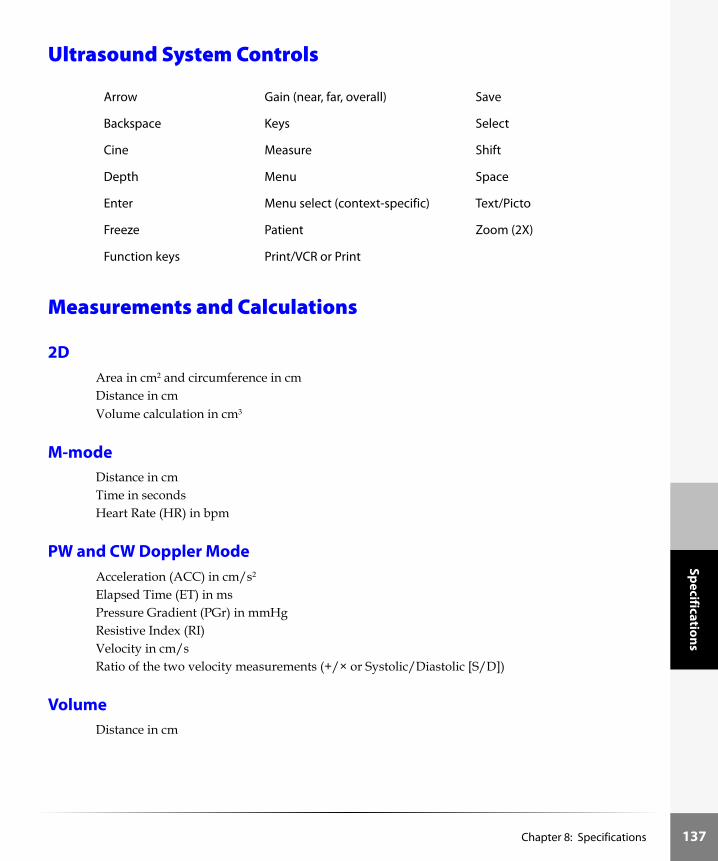
Specifications
Ultrasound System Controls
Measurements and Calculations
2DArea in cm2 and circumference in cmDistance in cmVolume calculation in cm3
M-modeDistance in cmTime in secondsHeart Rate (HR) in bpm
PW and CW Doppler ModeAcceleration (ACC) in cm/s2
Elapsed Time (ET) in msPressure Gradient (PGr) in mmHgResistive Index (RI)Velocity in cm/sRatio of the two velocity measurements (+/× or Systolic/Diastolic [S/D])
VolumeDistance in cm
Arrow Gain (near, far, overall) Save
Backspace Keys Select
Cine Measure Shift
Depth Menu Space
Enter Menu select (context-specific) Text/Picto
Freeze Patient Zoom (2X)
Function keys Print/VCR or Print
Chapter 8: Specifications 137

138
Spec
ifica
tion
s
Volume FlowDistance (2D distance) in cmTime Average Mean (Doppler Trace) in cm/s
Cardiac Calculations
2D ModeLeft Atrium/Aorta (LA/Ao)Cardiac Output (CO) in l/mEjection Fraction (EF), percentFractional LVD Shortening, percentHeart Rate (HR) in bpmInterventricular Septum (IVS) Thickening Fraction, percentLeft Ventricle End Volumes (Teichholz) in mlLVPW Thickening Fraction, percentStroke Volume Index (SV) in ml
M-modeAortic Valve Cusp Separation (AoVS) in cmLeft Ventricle Ejection Time (LVET) in secE-F Slope in cm/sE-Point Septal Separation (EPSS) in cm
PW and CW DopplerMitral Valve Inflow“A” Wave Peak Velocity (A) in cm/s“A” Wave Peak Pressure (A PG) in mmHgdP:dT in mmHg/s“E” Wave Peak Velocity (E) in cm/s“E” Wave Peak Pressure (E PG) in mmHgE:A ratio (E:A) Pressure Half Time (PHT) in m/secMitral Valve Area (MVA) from PHT in cm2Heart Rate (HR) in bpm
Left Ventricle Outflow TractMaximum Velocity (Vmax) in cm/sMaximum Pressure Gradient (PGmax) in mmHGVelocity Time Integral (VTI) in cmMean Velocity on peak trace (Vmean) in cm/sMean Pressure Gradient (PGmean) in mmHG
Chapter 8: Specifications

Specifications
Left Ventricular Outflow Track (LVOT D) diameter in cmLeft Ventricular Outflow Track Outflow area (LVOT area) in cm2Heart Rate (HR) in bpm
Aortic ValveMaximum Velocity (Vmax) in cm/sMaximum Pressure Gradient (PGmax) in mmHGVelocity Time Integral (VTI) in cmMean Velocity on peak trace (Vmean) in cm/sMean Pressure Gradient (PGmean) in mmHGAortic Valve Area (AVA) (derived from continuity equation) in cm2Stroke Volume (SV) in mlCardiac Output (CO) in l/minHeart Rate (HR) in bpm
Tricuspid Value InflowdP:dT in mmHg/sMaximum Velocity (Vmax) in cm/sMaximum Pressure Gradient (PGmax) in mmHgHeart Rate (HR) in bpm
Pulmonic ValveMaximum Velocity (Vmax) cm/sMaximum Pressure Gradient (PGmax) in mmHgVelocity Time Integral (VTI) in cmMean Velocity on peak trace (Vmean) in cm/sMean Pressure Gradient (PGmean) in mmHGHeart Rate (HR) in bpm
Obstetrical CalculationsAmniotic Fluid Index (AFI)Average Ultrasound Age (AUA)Estimated Date of Delivery (EDD) by Last Menstrual Period (LMP)Estimated Date of Delivery (EDD) by Average Ultrasound Age (AUA)Estimated Fetal AgeEstimated Fetal Weight (EFW)Gestational Sac (GS)Volume
Chapter 8: Specifications 139

140
Spec
ifica
tion
s
Fetal TablesAbdominal Circumference (AC)Antero Posterior Trunk Diameter (APTD)Biparietal Diameter (BPD)Crown Rump Length (CRL)Estimated Fetal Weight (EFW)Femur Length (FL)Fetal Trunk Cross-sectional Area (FTA)Gestational Sac (GS)Head Circumference (HC)Occipital-Frontal Diameter (OFD)Transverse Trunk Diameter (TTD)
VascularPW and CW DopplerProximal Common Carotid Artery (PCCA)Middle Common Carotid Artery (MCCA)Distal Common Carotid Artery (DCCA)BulbProximal Internal Carotid Artery (PICA)Middle Internal Carotid Artery (MICA)Distal Internal Carotid Artery (DICA)Proximal External Carotid Artery (PECA)Middle External Carotid Artery (MECA)Distal External Carotid Artery (DECA)Vertebral Artery (VArty)Ratio of MCCA to MICA (MICA/MCCA ratio = MICA/MCCA)
Image StorageUp to 119 images (depending on the configuration of your system)Cine review
Chapter 8: Specifications

Specifications
AccessoriesAIUM Ultrasound Medical Safety Guidance DocumentAudio cable (RCA/RCA)Battery (extra)Basic StandBasket for SiteStandBiopsy Guide Starter Kit for the C8/8-5 MHz curved array transducerBiopsy Guide Starter Kit for the C60/5-2 MHz curved array transducerBiopsy Guide Starter Kit for the ICT/7-4 MHz intracavitary transducerBiopsy Guide Starter Kit for the L38/10-5 MHz linear array transducerBiopsy Needle Guide/Sheath Replacement Kit for L38/10-5 and C60/5-2 transducersBracket for VCRCRT StandECG cableFlat Panel Display for the SiteStand mobile docking stationGrab and Go Carrying CasePC Direct serial cable (stereo/stereo)Power cord Power supply (extra)Premium carrying casePrinter control cableScanPack quick access carrierSerial cableSiteCharge dual battery chargerSiteLink image manager systemSitePack protective carrier packSiteStand mobile docking stationSonoKnowledge education packageUltrasound gelUser GuideVCR control cable (stereo/stereo)Video cable (RCA/BNC)Video cable (RCA/RCA)Video cable (RCA/Stereo)
Chapter 8: Specifications 141

142
Spec
ifica
tion
s
Peripherals
Medical GradeSee the manufacturer’s specifications for the following peripherals.Black-and-white printer*Color printerExternal video monitorVideo cassette recorder* Recommended sources for printer paper: Contact Sony at 1-800-686-7669 for the name and number of the local distributor.
Non-medical Grade (Commercial)Digital video recording/playback productExternal monitor (e.g., handheld or personal display)Battery chargerLithium battery
Temperature, Pressure, and Humidity LimitsNote: The temperature, pressure, and humidity limits apply only to the ultrasound system and transducers.
System Operating10–40°C (50–104°F), 15–95% R.H.700-1060hPa (0.7 ATM to 1.05 ATM)
System Shipping/Storage-35–65°C (-31–149°F), 15–95% R.H.500-1060hPa (0.5ATM to 1.05 ATM)
Battery Operating10–40°C (50–104°F), 15–95% R.H.
Battery Shipping/Storage-20–60°C (-4–140°F), 0–95% R.H.
Transducers Operating10–40°C (50–104°F), 15–95% R.H.
Chapter 8: Specifications

Specifications
Transducers Shipping/Storage-35–65°C (-31–149°F), 15–95% R.H.
ElectricalSystem optional: 100-120/220-240 VAC, 50/60 Hz input, 16 VDC output power adapterSiteCharge dual battery charger input voltage: 16.0 V, 2.8 ASiteCharge dual battery charger output voltage: 12.6V, 3.0 A. (2x)AC power adapter input: 100-120/220-240 VAC, 50/60 HzAC power adapter output: + 16VDC, 2.8 A
Battery6-cell, 11.1 VDC, 3.0 amp-hours, rechargeable lithium-ion battery packRun time: 1.5 to 4 hours, depending upon operating conditions
Electromechanical Safety StandardsEN 60601-1:1990, European Norm, Medical Electrical Equipment–Part 1. General Requirements for Safety.EN 60601-1-1:1993, European Norm, Medical Electrical Equipment–Part 1. General Requirements for Safety–Section 1-1. Collateral Standard. Safety Requirements for Medical Electrical Systems.EN 60601-1-2:1993, European Norm, Medical Electrical Equipment. General Requirements for Safety-Collateral Standard. Electromagnetic Compatibility. Requirements and Tests.EN 60601-2-25: 1995, European Norm, Medical Electrical Equipment–Part 2. Particular Requirements for Safety–Section 25. Specification for Electrocardiographs.The ECG cable meets safety requirements of EN 60601-2-25 for Type CF patient-applied part.C22.2, No. 601.1:1990, Canadian Standards Association, Medical Electrical Equipment–Part 1. General Requirements for Safety.CEI/IEC 61157:1992, International Electrotechnical Commission, Requirements for the Declaration of the Acoustic Output of Medical Diagnostic Ultrasonic Equipment.UL 2601-1:1997, Second Edition, Underwriters Laboratories, Medical Electrical Equipment-Part 1: General Requirements for Safety.
Chapter 8: Specifications 143

144
Spec
ifica
tion
s
EMC Standards ClassificationCISPR11:97, International Electrotechnical Commission, International Special Committee on Radio Interference. Industrial, Scientific, and Medical (ISM) Radio-Frequency Equipment Electromagnetic Disturbance Characteristics-Limits and Methods of Measurement.The Classification for the Sonosite system, SiteStand, accessories, and peripherals when configured together is: Group 1, Class A.
Airborne Equipment Standards (without ECG Cable attached)RTCA/DO160D:1997, Radio Technical Commission for Aeronautics, Environmental Conditions and Test Procedures for Airborne Equipment, Section 21.0 Emission of Radio Frequency Energy, Category B.
ECG StandardANSI/AAMI EC53-1995, Association for the Advancement of Medical Instrumentation, ECG Cables, and Lead Wires. The SonoSite ultrasound system meets the requirements of this standard except Section 4.4.1 (Exposure to ethylene oxide (EO) sterilization) and Section 4.5.9 (Connector retention force). The requirement in Section 4.5.9 does not apply, because the product weighs less than seven pounds.
Chapter 8: Specifications

Glossary
Chapter 9: Glossary
This glossary includes an alphanumeric listing of all system symbols and system terms.A “See” reference in the glossary refers you to the accepted SonoSite term. For example: rather than probe or scanhead, transducer is the accepted SonoSite term for this product.A “See also” reference in the glossary refers you to a term that is related to this term, or provides more information about this term. For example: 2D, M-mode, PW and CW Doppler, CPD, and DCPD imaging are the system imaging modes; they are cross-referenced in this glossary to provide related information about system imaging.The American Institute of Ultrasound in Medicine (AIUM) has published, Recommended Ultrasound Terminology, Second Ed., (1997). Refer to it for ultrasound terms not contained in this glossary.
Symbols
Zoom key, which is used for turning zoom on and off during live 2D, CPD, and DCPD imaging.
Save key, which is used for saving frozen images to memory.
Print/VCR key, which is used for printing images from the system when connected to a printer or starts and stops the recording mode of the VCR when VCR-SVHS is selected.
Print key, which is used for printing images from the system when connected to a printer
Menu key, which is used for turning the on-screen menu on and off.
Menu key (international symbol), which is used for turning the on-screen menu on and off (international devices only).
Backspace key, which deletes characters preceding the text cursor.
Text/picto key, which allows entry of text at the top-left of the image and allows display of pictograph.
Freeze key, which stops live imaging and displays the frozen image; backs out of image review and cancels batch printing.
Freeze key, (international symbol), which stops live imaging and displays the frozen image; backs out of image review and cancels batch printing.
Chapter 9: Glossary 145

146
Glo
ssar
y
Icons
Function key, which is used with the number keys (1-6) to display assigned text; used with the “I” key to display system information. See also f key, function key assignment, and annotation.
Depth key (international symbol), which is used to adjust the imaging depth for the 2D and M-mode images. The upper toggle decreases depth, and the lower toggle increases depth.
Cap lock key (international symbol), which is used to lock the keyboard in capitalization mode.
Cap lock key (international symbol, French), which is used to lock the keyboard in capitalization mode.
Shift key (international symbol), which is used to enter capitalized characters and non-English extended characters.
Space key (international symbol), which is used to place a space between text strings.
Enter key (international symbol), which is used to move the cursor among fields in patient function and returns the text cursor to the top-left corner of the image area.
Arrow keys, which are used for navigating a cursor through text annotations or listed measurements.
Cine arrow keys, which are used for reviewing stored or frozen images.
Print control connector, which is located on the left side of the system. The printer control cable is connected to the print control connector.
Brightness icon.
Contrast icon.
Unlock icon allows you to get to the license update screen.
Next page and previous page icons indicate additional pages in the patient report.
Biopsy icon indicates that the biopsy mode is on.
Arrow icon is used to annotate images.
Chapter 9: Glossary

Glossary
Icon for saved images, the number indicates how many images have been saved. The fill bar defines how full the system image storage memory is.
Menu item that returns you to the previous display.
Forward icon, which appears in menus and indicates that selecting the menu item displays another menu.
Battery icon, which appears when system is running on battery power and the AC power is not connected. When there is approximately 10 minutes of battery life remaining, the gray battery icon will flash. At 2 minutes of battery life remaining, the battery icon turns white and the system beeps.
AC power icon, which appears when the system is running on AC power and the battery is not installed.
Battery icon and AC power icon, which appears when AC power is connected and the battery is installed.
Calcs icon, which displays the measurement types and calculations available in the selected exam.
Distance caliper icon, which appears on the image and as a menu item.
Distance caliper icon, which appears on the image and as a menu item.
Ellipse caliper icon, which appears as a menu item that starts an ellipse measurement. Also toggles between the distance and ellipse measurements.
Delete menu item, which deletes a measurement and removes the measurement traces from the display or all text added to an image.
Transducer icon, which represents a transducer with M-mode turned on.
Transducer icon, which represents a transducer with PW Doppler turned on.
Transducer icon, which represents a transducer with CW Doppler turned on.
Transducer icon, which represents a transducer with CPD turned on.
Transducer icon, which represents a transducer with DCPD turned on.
List icon, which appears in menus, and indicates a list of selections.
Chapter 9: Glossary 147

148
Glo
ssar
y
Optimization icon, which appears in menus and indicates that selecting the menu item changes the optimization setting (see below).
Res or low, icon, which represents the resolution optimization setting in 2D. See also general and penetration.
Gen or med icon, which represents the general optimization setting in 2D and the medium optimization setting in CPD and DCPD. See also resolution and penetration.
Pen icon, which represents the penetration optimization setting in 2D. See also resolution and general.
Selection icon, which shows that there are more options for this menu item. Pressing menu select repeatedly, sequences through the options.
Maintenance icon, which indicates that system maintenance is required.
SonoSite logo. The logo appears when the system first starts up, at the top of the display, and on the SiteCharge dual battery charger.
SonoHeart logo. The logo appears at the top of the display and when the system first starts up.
Text entry icon, which indicates that a field accepts text entry.
Working icon, which indicates that the system is performing a background task.
Pictograph icon, which appears as a menu item; it is used to select the pictograph.
Print in progress icon, which indicates that an images or images are being printed.
Record in progress icon, which indicates that an image or images are being recorded.
Transducer marker, which appears on the pictograph to indicate the orientation of the transducer during the exam. This icon is moved with the trackball.
Angle correction, which appears as a menu item; it is used to turn on angle correction in PW Doppler mode.
Gate size, which appears as a menu item; it is used to adjust the gate size in PW Doppler mode.
Steering, which appears as a menu item; it is used to turn on steering in PW Doppler mode when a L38/10-5 transducer is connected to the system.
Chapter 9: Glossary

Glossary
Pulse repetition frequency (or scale), which appears as a menu item in PW Doppler spectral trace mode; it is used to change the velocity scale.
Baseline, which appears as a menu item in PW Doppler spectral trace mode; it is used to change the position of the baseline.
Invert, which appears as a menu item in PW Doppler spectral trace mode; it is used to invert the image.
Wall filter, which appears as a menu item in PW Doppler spectral trace mode; it is used to change the wall filter.
Sweep speed, which appears as a menu item in M-mode and PW Doppler spectral trace mode; it is used to set the sweep speed of the trace.
Auto trace, which appears as a menu in Doppler mode.
Manual trace, which appears as a menu item in PW and CW Doppler modes.
Set, which appears as a menu item in PW and CW Doppler modes.
Set (international), which appears as a menu item in PW and CW Doppler modes.
Hide calculations, a menu item when selected removes calculations from the image.
Show calculations, a menu item when selected displays calculations on the image.
Heart rate (HR), which appears as a menu item in M-mode; it is used to measure one heart beat cycle to calculate beats per minute (bpm).
Save measurement, which appears as a menu item; it is used to save measurements to the patient report.
Tissue Harmonic Imaging (THI), which appears as a menu item.
Orientation, which appears as a menu item; it is used to change the orientation of the image being displayed.
Pound sign symbol (###) is displayed on the patient report when an entry is not valid, e.g., value is too large or small.
###
Chapter 9: Glossary 149

150
Glo
ssar
y
Terms
2D (two-dimensional) imaging
A way to display echoes in two dimensions on a video display. Video pixels are assigned a brightness level based on echo signal amplitude. See also CPD and DCPD imaging.
acceleration (deceleration) time
A time period when a rate in change increases or decrease through a cardiac valve, measured in milliseconds.
accession An optional 16-character field assigned to each patient file by an institution for its internal information management purposes.
amniotic fluid index (AFI)
An OB measurement that provides a means to assess fetal status from the measurement of amniotic fluid in the maternal abdomen.
annotations Used to identify objects on the image display. See also f key and function key assignments.
aortic valve area (AVA)
A calculation determined from the CSA of the LVOT and peak velocities from the LVOT and aorta, measure in cm/sec2.
aortic valve cusp separation (AoVS)
The distance between the trailing echo of the anterior aortic valve leaflet and the leading echo of the posterior aortic valve leaflet in early systole.
as low as reasonably achievable (ALARA)
The guiding principle of ultrasound use, which states that you should keep patient exposure to ultrasound energy as low as reasonably achievable for diagnostic results.
audible beep A menu item used to turn on or off the audible beep, which is heard after the system prints all images.
audio, battery, date/time
A menu item used to access audible beep, sleep delay, power delay, and date/time.
average ultrasound age (AUA)
An estimate of the ultrasound age derived from the average of a number of fetal biometric measurements performed during an exam.
b-mode See 2D imaging.
battery The system uses an 11.1 volt, 3.0 amp-hour rechargeable lithium-ion battery.
beats per minute (BPM)
The heart rate is represented in beats per minute.
biopsy An icon that turns the biopsy guideline display on or off.
biopsy guidelines Display guidelines within the image representing the path along which a biopsy needle should pass.
Chapter 9: Glossary

Glossary
bodymarker See pictograph.
brightness A system control used to adjust the light output of the display.
brightness mode See 2D imaging.
cable, audio A cable, used with the SiteStand and VCR to prove audio capability.
cable, PC Direct A cable, used with the null-modem cable to connect a system directly to a PC for downloading images using SiteLink Image Manager.
cable, printer control A mini-jack to mini-jack connector-type cable, 10 feet (3.1 meters) long, connects the system to a video printer.
cable, video An RCA-to-BNC connector-type cable, 10 feet (3.1 meters) long, used to connect the system to an external video monitor or video printer.
cable, video An RCA-to-RCA connector-type cable, 10 feet (3.1 meters) long, connects the system to an digital video recorder.
cable, video An RCA-to-Stereo connector-type cable, 6 feet (1.8 meters) long, connects the system to a handheld monitor.
calcs (calculations) authors
A menu item used to select the biometric measurement and the author from which the calculation of the ultrasound age and estimated fetal weight are derived.
caliper A measurement cursor. See also cursor.
caliper line A menu item used to turn on or off a line connecting two calipers, which disappears as the calipers get closer together.
cap A system key used to lock the capitalization of text or labels.
cardiac output (CO) A cardiology calculation which appears on the patient report for the amount of blood pumped out of the heart per minute.
case, carrying A protective carrying case used to carry the system, one transducer, and supplies.
charger, SiteCharge dual battery
A charger system used to recharge one or two system batteries.
cine A series of images in image memory. When the freeze control is pressed, the cine arrow keys can be used for cine review of the images. See also cine arrow keys.
CPD imaging A way to display the Doppler, time-averaged, signal amplitude or signal intensity in tissue. See also 2D and DCPD imaging.
Chapter 9: Glossary 151

152
Glo
ssar
y
contrast A system control used to adjust the difference in light output between the light and dark parts of the display.
control All system user interface devices, excluding keys, menus, receptacles. See also keys, menus, and receptacles.
continuous wave (CW) Doppler mode
A Doppler recording of blood flow velocities along the length of the beam.
current patient A menu item used to display the current patient data. See also new patient and patient information.
cursor An icon used to locate a point on the display. See also caliper.
curved array (C60/5-2)
A transducer used for abdomen, obstetrics, and gynecology exams. It is normally identified by the letter C (curved or curvilinear) and a number (60). The number corresponds to the radius of curvature of the array expressed in millimeters. The transducer elements are electrically configured to control the characteristics and direction of the acoustic beam. See also intracavitary, linear, and microcurved transducer.
date/time A menu item used to set the correct date and time.
delete all images A menu item used to display a menu from which you can delete all saved images.
delta pressure: delta time (dP:dT)
The change in pressure compared to the change in time.
depth A system control used to adjust the maximum depth of the image display. A constant speed of sound of 1540 meters/second is assumed in the calculation of echo position in the image.
depth markers A scale of markers along the right of the image. The small markers represent 1 centimeter (cm), the larger markers represent 5 cm.
diameter (D) A two-dimensional width measurement, measure in cm.
DICOM Digital Imaging and Communications in Medicine
Directional Color Power Doppler (DCPD) imaging
A way to display the Doppler, time- averaged, signal amplitude or signal intensity in tissue to visualize the presence of detectable blood flow and the direction of blood flow. See also 2D and CPD imaging.
display The viewable region of the LCD/video monitor on which the ultrasound image and other display elements appear.
done A menu item used to return to the previous display or return to imaging.
Chapter 9: Glossary

Glossary
Doppler amplitude mode
See CPD imaging.
E:A ratio E velocity/A velocity, pertaining to the two peaks in a mitral valve Doppler spectrum.
echo curve 1 (EC1) and echo curve 2 (EC2)
These two cardiac image examination types are suitable for general use to obtain a baseline image, as it displays more dynamic imaging with details on tissue characteristics. The choice between EC1 and EC2 depends on the patient body-type and the operator’s preference.
echo curve 3 (EC3) This is a cardiac image exam, notation type setting that emphasizes image contrast.
E-F slope Is the rate of decay of the passive ventricular filling.
ejection fraction (EF) A cardiac calculation that appears in the patient report. A calculation quantifying the left ventricular systolic function, reported in a percentage.
electrocardiogram (ECG)
A visual record the heart’s electrical activity used for accurate timing of diastolic and systolic function of the heart.
energy mode See CPD imaging.
enter A key used to move a cursor from one field to the next.
e-point septal separation (EPSS)
Is the distance between the mitral valve E point and the posterior edge of the interventricular septum at the same point in time.
estimated delivery date (EDD)
EDD by average ultrasound age (AUA) and by last menstrual period (LMP) date appear in the patient report, if there are corresponding measurements and an LMP from which to estimate them.
estimated fetal age (EFA)
An estimate of the fetal age based on one or more fetal biometric measurements.
estimated fetal weight (EFW)
An estimate of the fetal weight based on one or more fetal biometric measurements.
exam A menu item used to access a list of exam types. The exam type appears in abbreviated form in the upper right section of the image display.
exam/patient information
A system control used to access exam type, current patient, or new patient.
Chapter 9: Glossary 153

154
Glo
ssar
y
Exam type abbreviations
Abd: Abdomen Neo: NeonatalBre: Breast OB: ObstetricsChe: Chest Pro: ProstateEC1: Echo Curve 1 SmP: Small PartsEC2: Echo Curve 2 Sup: SuperficialEC3: Echo Curve 3 Vas: VascularGyn: Gynecological
f keys Numbered keys (1-6) with assigned text used with the function key to display text annotation.
far A system control used to adjust the amplification of deeper echoes. See also gain and near.
field An area on the display, usually associated with text entry or the location of a display element.
freeze A system control used to stop image acquisition. Also allows you to view the current image and use the cine arrow keys to view a cine series.
function key assignment
A menu item used to access the list of labels assigned to each function key. See also f keys, function key, and annotations.
gain an ultrasound term defined as the ratio of the output signal amplitude to the input signal amplitude. Usually expressed in decibels or as a percentage. A system control used to adjust the amplification of the echoes in the image display. See also far and near.
general (gen) a 2D and a DCPD imaging optimize setting. For 2D, see also penetration and resolution. For DCPD, see high.
heart rate (HR) The heart rate, in beats per minute, is a cardiology entry that appears on the patient report.
hide A screen information setting that controls the display of the optimize setting, time, memory number, and patient information. See also show.
high A CPD and DCPD imaging optimization setting. See also low and medium.
icon A pictorial representation. See also pictograph and cursor.
id A field into which patient identification is entered. The current patient or new patient information is available from the patient information menu item.
image display The ultrasound image.
Chapter 9: Glossary

Glossary
image memory As images are acquired and processed, they are stored in image memory. Pressing freeze enables a cine review, which allows you to review the cine series in image memory. See also cine.
in situ In the natural or original position.
intracavitary transducer (ICT/7-4)
A transducer used for obstetrics, gynecology, and prostate exams. The transducer elements are electrically configured to control the characteristics and direction of the acoustic beam. See also curved, linear, and microcurved transducer.
IVT (intravaginal transducer)
See intracavitary transducer.
keyboard Used to enter labels or individual alphanumeric characters on the display.
last menstrual period (LMP)
The last menstrual period date entered into patient information. It is used to calculate the estimated delivery date (EDD) by LMP, which is displayed in the patient report.
left atrium/aorta Ratio of the left atrium and aortic root diameter.
linear array transducer (L38/10-5)
A transducer used for small parts imaging (thyroid, testicular, musculoskeletal tissue); breast imaging; vascular imaging; and ultrasound guided procedures: line placements and biopsies. It is normally identified by the letter L (linear) and a number (38). The number corresponds to the radius of width of the array expressed in millimeters. The transducer elements are electrically configured to control the characteristics and direction of the acoustic beam. See also curved, intracavitary, and microcurved transducer.
low A CPD and DCPD imaging optimize setting. See also high and medium.
low battery An icon on the right side of the display. It indicates the need to charge the system battery.
M-mode Motion Mode showing the phasic motions of the cardiac structures. A single beam of ultrasound is transmitted and reflected signals are displayed as dots of varying intensities, which create lines across the screen.
measure A system control used to start a measurement on the image. There are two types of measurements, distance and area.
mechanical index (MI)
An indication of the likelihood of mechanical bioeffects occurring: the higher the MI, the greater the likelihood of mechanical bioeffects. See Chapter 5, “Safety” for a more complete description of MI.
medium (med) A CPD and DCPD imaging optimize setting. See also high and low.
Chapter 9: Glossary 155

156
Glo
ssar
y
memory A menu item with two settings: show and hide. It is used to display the image memory icon.
menu A list of menu items on the display. Along the left side of the display there are five controls. Pressing one of the controls, selects the menu item adjacent to the control. An ellipsis adjacent to a menu item denotes that the selection of the menu item will display another menu.
MI/TI See mechanical index and thermal index.
microcurved broadband array transducer (C15/4-2)
A transducer used for cardiology, abdominal, and thoracic imaging. It is normally identified by the letter C (curved) and a number (15). The number corresponds to the radius of curve of the array expressed in millimeters. The transducer elements are electrically configured to control the characteristics and direction of the acoustic beam. See also curved, intracavitary, and linear transducer.
mitral valve area (MVA)
A calculation based on the pressure half time (PHT) of the area of the mitral valve in cm/sec2.
name A field into which the patient name is entered. The current patient or new patient information is available from the patient information menu item.
near A system control used to adjust the amplification of shallower echoes. See also far and gain.
neonatal microcurved broadband array transducer (C11/7-4)
A transducer used for neonatal cranium, abdomen, heart and pelvis imaging and pediatric and adult vascular access. It is normally identified by the letter C (curved) and a number (11). The number corresponds to the radius of curve of the array expressed in millimeters. The transducer elements are electrically configured to control the characteristics and direction of the acoustic beam. (See also curved, intracavitary, linear, and microconvex transducer.)
new patient A menu item used to enter new patient information. Selecting new patient deletes the current patient's information and any corresponding report pages.
NTSC (National Television Standards Committee)
A video format setting. See also PAL.
Optical Character Recognition (OCR)
Used for DICOM purposes.
Chapter 9: Glossary

Glossary
optimize A system control with three settings in 2D imaging: resolution, general, and penetration. It is used to adjust the 2D echo reception characteristics for body type. In CPD and DCPD imaging, there are three settings: high, medium, and low. It is used to adjust system sensitivity to high, medium, or low amplitude signals. It has two settings: show and hide. See Table 1, “Transducer, Exam Type, and Imaging Mode” on page 27.
orientation marker A marker located adjacent to the image display indicating the scan plane orientation.
orient image A menu item used to select one of four image orientations. It has four settings: upper left, upper right, down left, and down right.
PAL (phase alternating line)
A video format setting. See also NTSC.
patient information A menu item used to access the current patient and new patient information. See also current patient and new patient.
peak velocity A Doppler measurement of the peak velocity. E, A, and Vmax in the cardiac package are peak systolic velocity measurements.
penetration (pen) A 2D optimize setting. See also general and resolution.
pictograph (picto) (1) a menu item used to select among a set of pictographs. A pictograph is a pictorial representation of an object. Sometimes referred to as a bodymarker. (2) a system setup that turns the pictographs on or off. See also text-picto.
power delay A menu item used to set the power delay to off, 15, or 30 minutes.
power switch Turns system power on or off. The power switch is located on the back, left of the system handle.
pressure gradient A calculation for the pressure difference between two chambers of the heart, measured in mmHG.
pressure half time (PHT)
A calculation of the mitral valve to quantify the degree of stenosis.
printer A device used to print images.
print all images A menu item used to print all saved images.
probe See transducer.
pulsatility index (PI) A generic calculation of the S-D/mean.
pulsed wave (PW) Doppler mode
A Doppler recording of blood flow velocities in a range specific area along the length of the beam.
Chapter 9: Glossary 157

158
Glo
ssar
y
resolution (res) A 2D optimize setting. See also general and penetration.
resistive index (RI) A generic calculation of the S-D/S.
review images A menu item used to review stored individual images.
scanhead See transducer.
select A system control used to set a measurement caliper, set the scan plane marker in a pictograph, and initiate other system actions.
setting A value assigned to a system parameter. See also setup.
setup System parameters used to customize the display and system operation. See also setting.
shift A key used to enter capital letters and alternative keyboard characters.
show A screen information setting that controls the display of the optimize setting, time, memory number, and patient information. See also hide.
SiteCharge dual battery charger
A charger system used to recharge system batteries.
SiteStand mobile docking station
A stand used to secure the system. It provides a mobile work platform, receptacles for using AC power and recharging the battery, a receptacle for an external video monitor, printer, and image transfer to a PC.
skinline A depth on the image display that corresponds to the tissue/transducer interface.
sleep delay A menu item used to set the sleep delay to off, 5, or 10 minutes.
space A key used to enter a blank space on the display.
stroke volume (SV) A calculation for quantifying the left ventricle performance measured in ml.
system setup A menu item used to access OCR, TI, picto, Doppler; screen information; audio, power, date/time; and video, printer/VCR, calcs, f keys.
systolic/diastolic ratio (S/D ratio)
A ratio of the systolic velocity divided by the diastolic velocity.
text/picto (pictographs)
A system control used to initiate text entry, activate a pointer, to display pictographs, and activate the biopsy guidelines (when a biopsy capable transducer is connected). The trackball is used to move the pointer and the position of the transducer marker over the pictographs. See also pictograph.
Chapter 9: Glossary

Glossary
TIB (bone thermal index)
A thermal index for applications in which the ultrasound beam passes through soft tissue and a focal region is in the immediate vicinity of bone.
TIC (cranial bone thermal index)
A thermal index for applications in which the ultrasound beam passes through bone near the beam entrance into the body.
TIS (soft tissue thermal index)
A thermal index related to soft tissues.
thermal index (TI) The ratio of total acoustic power to the acoustic power required to raise tissue temperature by 1°C under defined assumptions. See Chapter 5, “Safety” for a more complete description of TI.
time A menu item with two settings: show and hide. It is used to show or hide the time display.
time average mean (TAM)
A calculation of the mean time measured in cm/sec.
tissue harmonic imaging (THI)
Transmits at one frequency and receives at a higher harmonic frequency to reduce noise and clutter and improve resolution.
trackball A system control used to move objects on the image display.
transducer A device that transforms one form of energy into another form of energy. Ultrasound transducers contain piezoelectric elements, which when excited electrically, emit acoustic energy. When the acoustic energy is transmitted into the body, it travels until it encounters an interface, or change in tissue properties. At the interface, an echo is formed that returns to the transducer, where this acoustic energy is transformed into electrical energy, processed, and displayed as anatomical information. See curved, intracavitary, linear, and microcurved transducer.
velocity time integral (VTI)
A calculation of a sum of the velocities.
video format A menu item used to select NTSC or PAL. See also NTSC and PAL.
volume A calculation of three, 2D measurements taken to calculate the volume of the imaged tissue or space.
volume flow A calculation to quantify blood flow.
working A process that describes when the system is working on a background task, such as printing
+/× ratio A ratio of the “+” caliper over the “x” caliper.
Chapter 9: Glossary 159

160
Glo
ssar
y
Acronyms
Acronym Description
A “A” Wave Peak Velocity
A PG “A” Wave Peak Pressure Gradient
AC Abdominal Circumference
ACC Acceleration
Ao Aorta
AFI Amniotic Fluid Index
AoD Aortic Root Diameter
AoVS Aortic Valve Cusp Separation
AT Acceleration (Deceleration) Time
APTD Anteroposterior Trunk Diameter
AUA Average Ultrasound Age
AV Aortic Valve
AVA Aortic Valve Area
BPD Biparietal Diameter
BPM Beats per Minute
CO Cardiac Output
CCA Common Carotid Artery
CPD Color Power Doppler
CRL Crown Rump Length
CW Continuous Wave Doppler
D Diameter
DCPD Directional Color Power Doppler
dP:dT Delta Pressure: Delta Time
E “E” Wave Peak Velocity
E PG “E” Wave Peak Pressure Gradient
Chapter 9: Glossary

Glossary
E:A E:A Ratio
ECG Electrocardiogram
EDD Estimated Delivery Date
EDD by AUA Estimated Delivery Date by Average Ultrasound Age
EDD by LMP Estimated Delivery Date by Last Menstrual Period
EF Ejection Fraction
EF SLOPE E-F Slope
EFW Estimated Fetal Weight
EPSS “E” Point Septal Separation
ET Elapsed Time
FL Femur Length
FTA Fetal Trunk Area
GS Gestational Sac
HC Head Circumference
HR Heart Rate
IVS Interventricular Septum
IVSFT Interventricular Septum Fractional Shortening
LA Left Atrium
LA/Ao Left Atrium/Aorta
LMP Last Menstrual Period
LVD Left Ventricular Dimension
LVDFS Left Ventricular Dimension Fractional Shortening
LVEDV Left Ventricular End Diastolic Volume
LVESV Left Ventricular End Systolic Volume
LVET Left Ventricular Ejection Time
LVOT Left Ventricular Outflow Track
Acronym Description
Chapter 9: Glossary 161

162
Glo
ssar
y
LVOT area Left Ventricular Outflow Track Area
LVOT D Left Ventricular Outflow Track Diameter
LVPW Left Ventricular Posterior Wall
LVPWFT Left Ventricular Posterior Wall Fractional Thickening
MV Mitral Valve
MVA Mitral Valve Area
OFD Occipital Frontal Diameter
PGr Pressure Gradient
PGmax Maximum Pressure Gradient
PGmean Mean Pressure Gradient
PHT Pressure Half Time
PI Pulsatility Index
PV Pulmonic Valve
PW Pulsed Wave Doppler
RI Resistive Index
RVD Right Ventricular Dimension
RVW Right Ventricular Free Wall
S/D Systolic/Diastolic Ratio
SV Stroke Volume
TAM Time Average Mean
TTD Transverse Trunk Diameter
TV Tricuspid Valve
Vmax Maximum Velocity
Vmean Mean Velocity
Vol Volume
VF Volume Flow
Acronym Description
Chapter 9: Glossary

Glossary
VTI Velocity Time Integral
+/× “+” Caliper/”×” Caliper Ratio
Acronym Description
Chapter 9: Glossary 163

164
Glo
ssar
y
Chapter 9: Glossary

Index
Index
Numerics2D and M-mode 612D imaging
brightness and contrast 28definition 150depth 29gain 29image orientation 29optimize 29return to 29turn on 29turn on THI 30viewing angle 28
2D measurementsdelete 44distance 43ellipse 44exit 44
Aabdominal circumference (AC). See OB
calculationsabdominal, intended uses 83AC power
use 10acceleration (ACC)
reference 126set up 46
acceleration time (AT) reference 126accession 25, 150accessories 141accuracy, measurement 123acoustic measurement precision 97acoustic output
measurement 81tables 88–94
age, fetal 55airborne equipment standards 144ALARA principle 79, 150amniotic fluid index (AFI). See OB calculationsangle correction 33angle, viewing 28
annotating images 37arrow 37pictograph 38pre-defined text 38text 37transducer marker 38, 39
annotations 150aortic valve area (AVA)
calculation 65definition 150reference 126
applications 136arrows definition 147assistance, customer 1audible beep
definition 150turn on/off 18
audio, battery, date/timedefinition 150setup 18
authors (calcs) 22average ultrasound age (AUA)
calculation 55definition 150
Bbaseline 34battery
charge 14check 14definition 150install 9remove 9safety 73specification 142, 143
beats per minute (BPM) 150biological safety 74biopsy 150biopsy guideline 150biparietal diameter (BPD). See OB calculationsB-mode See 2D imagingbodymarker 151
Index 165

166
Inde
x
brightnessdefinition 151mode 151
Ccable 151calcs (calculations)
authors 22calculations (calcs)
cardiac 59cardiac. See also cardiac calculationsOB 54vascular 57volume 50volume flow 52
caliper 151caliper line 151cap 151cardiac
perform calculations 63–68references 126specifications 138–139
cardiac calculations2D and M-mode 61AVA 65CO 67Doppler 62dP:dT 65E, A, and Vmax 63HR 68PHT 64SV 67VTI 64
cardiac output (CO)calculation 67definition 151reference 126
cardiac, intended uses 83case, carrying 151charger. See SiteStand SiteCharge dual battery
chargercine
arrows 151definition 151review 30, 31, 35
cine review
2D mode 30M-mode 31PW Doppler 36
cleaningECG cables 107system 104transducer cables 107transducers 105
color power Doppler imaging. See CPD imagingcontinuous wave (CW) Doppler. See CW Doppler
imagingcontrast 152
display 28control 152controls, system 137coupling gel. See gelCPD imaging
gain 32optimize 32region of interest 32return to 2D imaging 32turn on 32
cross sectional area (CSA) reference 126current patient
definition 152setup 25
cursor 152CW Doppler imaging
baseline 34cine review 36definition 152Doppler scale 35Doppler volume 35invert 35pulse repetition frequency (PRF) 34return to 2D imaging 36sample line 33spectral trace 34steering 33sweep speed 35turn on 33wall filter 35
CW Doppler measurements 45
Ddate/time
Index

Index
definition 152set 18
DCPD imaginggain 32optimize 32region of interest 32return to 2D imaging 32turn on 32
default settingschange to 23
delete all images 41, 152delta pressure; delta time (dP:dT)
calculation 65definition 152reference 127
depthadjust 29definition 152markers 152
derated intensity 81direct controls 80directional color power Doppler imaging. See
DCPD imagingdisinfectants
compatibility table 109–120recommended 103
disinfectingECG cables 107system 104transducer cables 107transducers 105
displaydefinition 152elements 136pictograph 38transducer marker 38
distance measurementperform 43
docking station. See SiteStand mobile docking station
done 152Doppler amplitude mode 153Doppler measurements
acceleration (ACC) 46elapsed time (ET) 46pressure gradient (PGr) 46ratio (+/× or S/D) 46
resistive index (RI) 46trace-automatic 49trace-manual 48velocity 46
Doppler scalechange 35
EE, A, and Vmax measurements 63E:A ratio reference 127ECG monitoring
optimize 36turn on 36
echo curveEC1, EC2, EC3 153
EDD by AUA 130EDD by LMP 130ejection fraction (EF)
calculation 60definition 153reference 127
elapsed time (ET)reference 127set up 46
electricalsafety 71specifications 143
electromagnetic compatibility 75electromechanical safety standards 143ellipse
measurement 44turn off 44
EMC classification standards 144energy mode 153enter 153equipment
protection 73survey 82
error message 72errors
acquisition 125algorithmic 125measurement 125
estimated delivery date (EDD)definition 153reference 130
Index 167

168
Inde
x
estimated fetal weight (EFW)definition 153reference 131
examafter 42definition 153exam/patient information 25, 153prepare for 25
exam typetransducer 27
exit measurements 44
Ffemur length (FL). See OB calculationsfetal age
calculate 56inaccurate calculation 102
fetal tables 140fetal trunk area (FTA). See OB calculationsfield 154freeze 154function keys
set up 22
Ggain
adjust 29definition 154gate size 33
gel, couplingapply 25
general (gen)definition 154set 29
gestational sac (GS). See OB calculationsglobal maximum values 95grace period 5guidance documents, related 81gynecology, intended uses 83
Hhead circumference (HC) 132heart rate (HR)
definition 154measure in Doppler 68
measure in M-mode 45reference 127
height, system 135hide calculations 49, 154high
definition 154set up 32
humidity limits 142
Iicons
defined 154list 146–149
IDdefinition 154set up 25
imageannotate 37cancel 40display 154freeze 30, 31, 35memory 155orientation 29poor quality 101print 40record 42review 41zoom 30
image mode, transducer 27image orientation
change 29images, all
delete 41print 40
imaging2D 28CPD 32, 151CW Doppler 33, 152DCPD 32, 152M-mode 30, 155PW Doppler 33, 157tissue harmonic imaging (THI) 159
in situ definition 155in situ intensity 81indirect controls 80infertility, intended uses 83
Index

Index
intended uses 83–85interventional, intended uses 83interventricular septum (IVS) reference 127intraoperative, intended uses 83invert 34IrfanView software 24
Kkeyboard 3, 155
Llabeling symbols 98last menstrual period (LMP) 25, 155left atrium/aorta (LA/Ao) reference 126left ventricular dimension (LVD) reference 128left ventricular posterior wall fractional
thickening (LVPWFT) reference 128license key 5
install 12obtain 11
license update screendisplay 13
low 32, 155low battery 155
Mmaintenance 103marker
display 38, 39mean pressure gradient (PGmean) reference 128mean velocity (Vmean) reference 128measure 155measurement
2D distance 432D ellipse 44acceleration (ACC) 46CW Doppler 45delete 44elapsed time (ET) 46exit 44heart rate 45hide 49M-mode 44PW Doppler 45
ratio +/× or S/D 46resistive index 46show 49specifications 137terminology, publications 125trace 48
measurement accuracy 1232D measurements and calculations 123caliper placement 123display size 123
measurement errorsacquisition error 125algorithmic error 125
measurement labelsdelete measurement. See specific measurement
or calculationexit calculation. See specific measurement or
calculationreview saved measurement. See specific
measurement or calculationmeasurement, view or repeat. See specific
measurement or calculationmeasurements and calculations
2D measurements 43cardiac, 2D and M-mode calculations 59–62cardiac, Doppler calculations 62–68Doppler (PW, CW) measurements 45M-mode measurements 44OB calculations 54vascular calculations 57volume calculations 50volume flow calculations 52
mechanical index (MI) 155medium 32, 155memory 156menu 156MI/TI 156mitral valve area (MVA) reference 128M-mode
cine review 31freeze 31return to 2D 31sample line 30sweep speed 31trace 31
M-mode measurements 44delete 45
Index 169

170
Inde
x
distance 44heart rate 45
monitoradjust 28brightness 28contrast 28specifications 135
Nname
definition 156set up 25
neonatal, intended uses 84new patient
definition 156setup 25
NTSC 156definition 156setup 21
OOB
calculations 54perform calculations 56set up calculation authors 22
obstetrical references 129obstetrical, intended uses 84occipito-frontal diameter (OFD). See OB
calculationsOCR feature
turn on or off 19optimize 157orient image
definition 157set up 29
orientation marker 157output display 80
PPAL
definition 157set up 21
patient information 157enter 25
patient report 69peak A pressure gradient (A PG) reference 128peak E pressure gradient (E PG) reference 128peak pressure gradient (PGmax) reference 128pediatric, intended uses 84penetration (PEN)
definition 157set up 29
peripherals 142physical dimensions 135pictograph 38, 39, 157
icon 148problems 102
powerswitch 157turn on 8
power delay 157set 18
precision, acoustic measurement 97pressure 142pressure gradient (PGr) reference 128pressure half time (PHT)
calculation 64definition 157reference 129
printerproblem 102set up 19
printing imagescancel 40print 40print all 40
probe. See transducerprostate, intended uses 84pulse repetition frequency (PRF) 34pulsed wave (PW) Doppler. See PW Doppler
imagingPW Doppler imaging
angle correction 33baseline 34cine review 36Doppler scale 35Doppler volume 35gain 35gate size 33invert 35pulse repetition frequency 34
Index

Index
return to 2D imaging 36sample line 33spectral trace 34steering 33sweep speed 35turn on 33wall filter 35
PW Doppler measurements 45
Rratio +/×, S/D 46receiver controls 80recording images 42recording problem 102references
cardiac 126general 132obstetrical 129
report 69resistive index (RI), measure 46resolution 158review images 41
Ssafety
electromagnetic compatibility 75maintenance 103standards, electromechanical 143
save images 41scanhead. See transducerselect 158set 158setup 158shift 158show 158SiteCharge dual battery charger
definition 158indicator light table 16use 16
SiteLink Image Management software 23SiteStand mobile docking station
definition 158use 23
skinline 158sleep delay
definition 158set up 18
softwareIrfanView 24license 5SiteLink Image Management 23upgrade 10
space 158standards
airborne equipment 144ECG 144electromechanical 143EMC classification 144
steering 33sterilizable transducers 107storage
image 140specifications 142
stroke volume (SV)calculation 67definition 158reference 129
superficial, intended uses 84symbols list 145symbols, labeling 98system
software 5turn on/off 8upgrade software 10wake up 8
system information screendisplay 13
system set upsleep delay 18
system setupaudible beep 18date and time 18definition 158OCR 19power delay 18printer 19thermal index 18use 17
system surfacesclean and disinfect 105
Index 171

172
Inde
x
Ttemperature limits, system 142text entry problems 102text, enter 37text/picto
definition 158enter 37
thermal indexproblems 102set 18
thermal index (TI) 159time
set 159tissue harmonic
definition 159turn on 30
tissue models 82trace
automatic 49manual 48
trackball 159transducer
cables, clean 107clean 105connect 7curved array (C11/7-4) 156curved array (C60/5-2) 152definition 159disinfect 105exam type 27icon 147imaging modes 27intracavitary (ICT/7-4) 155intravaginal (IVT). See intracavitary
transducerlinear array (L38/10-5) 155microcurved array (C15/4-2) 156problems 102remove 8specifications 135sterilizable 107
transducer coverinstall 26
transducer marker 38, 39transducer, exam type, and imaging mode table 26transverse trunk diameter (TTD). See OB
calculations
troubleshooting table 102
Uultrasound
controls 137terminology 145
user guide, conventions used 1uses, intended 83–85
Vvascular calculations
assign 58delete 59
vascular, intended uses 85VCR
problem 102record 42setup 21
velocity time integral (VTI)calculation 64definition 159reference 129
velocity, measure 46video
format 159video monitor
setup 21view patient report 69volume
definition 159perform calculation 50, 53
volume flow (VF)definition 159perform calculation 53
Wwake the system 8warnings 71water-value intensity 81working 159
Index

Index
Zzoom
problem 101set up 30
Index 173

174
Inde
x
Index


P02614-03