soutions w.9.5 january 2012 refrigeration past, present
TRANSCRIPT

© Copyright 2012 KE2 Therm Solutions, Washington, Missouri 63090
Refrigeration Past, Present and Futureby Brian Dolin - Senior Training Manager, KE2 Therm Solutions, Inc.
W.9.5 January 2012thermsolutions
No one has a crystal ball to predict the future but consid-ering history and current needs of the market allow some predictions with reasonable certainty.
PastCooling with ice has been around for thousands of years and the Romans, known to bring ice and snow from the Alps to cool their wine, gave us the term “refrigeration” from the word frigor-coldness.
It is easy to forget that the basic term we use daily for descrip-tion of load is the “ton” which is the amount of heat needed to melt or freeze one ton of water in 24 hours. This translates into 12,000 Btu/hr or 144 Btu per pound. Modern texts and calcula-tions use metric units such as kiloJoules per kilogram, but some of the pioneering work in thermodynamics was done in England and Scotland in the 18th century and the British Thermal Unit (BTU or Btu) was used frequently by 1870.
Our basic process of vapor compression refrigeration is often credited to an American physician, John Gorrie, who was grant-ed U.S. patent 8080 in 1851. Interestingly, his design used air as a primary refrigerant and merely compressed and re-expanded it without changing its state from liquid to gas.
Other pioneers in the field of modern style phase change re-frigeration are Ferdinand Carré of France, and Americans Jacob Perkins and Oliver Evans. By the end of the 19th century, vapor compression, mechanical refrigeration was in common indus-trial use for ice production and food processing.
Early systems used materials not often found in modern sys-tems, such as sulfur dioxide, ether and methyl chloride, which proved to be toxic, explosive, or both. Surprisingly, some of the earliest systems used Carbon Dioxide (CO2) and Ammonia, which seem to have been “rediscovered” in recent years for their efficiency and lack of ozone depletion potential.
Although specialty cooling methods, like Peltier-thermoelectric and vortex tubes, have been around for many decades, efficien-cies and scalability limit their use.
PresentMost systems used today are based on compression of a cool low pressure vapor into a hot, high pressure vapor. This hot va-por is condensed into a liquid by removing heat in a heat ex-changer called a condenser. The resultant liquid is allowed to expand into a vapor by dropping its pressure. This expanding liquid-vapor mix is admitted to another heat exchanger, the evaporator, which provides cooling by absorbing the heat from the space or other fluid. See Figure 1.
It is likely that for the near term, perhaps 10 to 15 years, vapor compression refrigeration will continue to be the standard means of providing cooling. Advances will be incremental,
rather than any revolutionary new technology being discovered or adopted.
Current needs of the market are really based on two factors: energy conservation and environmental effect. Of course, both are related and improvements in one can lead to improvements in the other. According to average U.S.EPA eGRID data, every kilowatt generated also generates 1.3 pounds of CO2 emis-sions, so energy efficiency has a direct effect on global warming potential.
Currently, to build electrical power plants cost over $2,100 per kW generated for fossil fuel and between $3,000 and $4,000 per kW for nuclear power generation. It may take more than a decade for a new plant to come on line, and political pressures concerning the environmental effects of fossil fuel burning and nuclear waste may increase time and costs significantly. Utilities may be unwilling or unable to commit the $2+ billion needed to capitalize new plants, particularly in the present economic climate.
The present and short term alternative is conservation of exist-ing resources to slow the need for new generating capacity. Al-most every utility will grant rebates or incentives to customers who show energy savings. For residential customers who switch to more efficient CFL compact fluorescent lighting, the rebate may be 100s of dollars, for industrial and commercial customers, the rebates may amount to 100s of thousands of dollars. Almost all parts of a refrigeration system can be made more efficient with new products and technologies, and many will qualify for these incentives.
Figure 1 - Basic Refrigeration System
Liquid/Vapor Mix
Restrictor,TEV or EEV
Warm Liquid
Cold Vapor
Hot Vapor
Warm Air
Cold Air
Evaporator
Compressor
Condenser

© Copyright 2012 KE2 Therm Solutions, Washington, Missouri 63090
Refrigeration Past, Present and Future
W.9.5 January 2012Page 2
thermsolutions
CompressorsCompressor technology continues to make some improve-ments in efficiency with better materials, and moderate design changes, but probably the best means of conservation will in-volve changes in refrigerants and adoption of variable speed drives. Natural refrigerants like carbon dioxide, ammonia and propane can be used to ameliorate the environmental impact of the inevitable loss of system refrigerant. In some applications, these replacement refrigerants save energy as well. Possibly the best avenue for savings in any motor driven device will be vari-able speed technology. Slowing the speed of a compressor will yield very high savings in terms of input power required. Since most systems do not run at full load very often, the savings can be significant. Some manufacturers quote up to 40% energy savings for variable speed compressors. Lubrication concerns have limited the use of variable speed drives on compressors in the past, but newer compressors have been designed with speed control in mind.
CondensersOften ignored in plans to save energy, particularly in supermar-ket refrigeration systems, are the condenser fans and pumps. The Fan Affinity Laws state that air or water volume delivered by a fan or pump is directly proportional to the fan or impeller speed. However, the power used by the fan or pump varies as the cube (X3) of the speed. In essence, dropping the speed by half will decrease power used by a factor of 8.
Based on design conditions, a majority of systems run a major-ity of the time at reduced speed and load. Figure 2 illustrates the run-time versus load data, which is fairly consistent for all geographical areas.
A typical air cooled condenser on a supermarket may use 75,200 kW per year and there may be 4 such units on each store. The power used, just for fans, on each store can amount to over
300,000 kW per year. Variable Frequency Drive (VFD) fan con-trols have been shown to save 50%+ of this energy and, in this instance, would prevent 195 tons of CO2 emissions.
The benefits and energy savings accruing from the use of VFDs on condenser fans is well proven and supported by utilities in the form of rebates and incentives. However, most refrigeration mechanics rarely need to program VFDs, or may not be familiar with them. Most VFDs in the market have hundreds of param-eters that must be set, or at least investigated. A solution that offers a completely programmed, wired and tested plug-and-play VFD fan controls can deliver the energy savings and rebate potential, while not requiring excessive time, effort and cost on the part of the installer.
EvaporatorsThe work to be done in any refrigeration system is realized in the evaporator but the technology to increase the efficiency of the evaporator has lagged behind the improvements to the com-pressor and condenser. The last large increase in the evapora-tor efficiency probably occurred when the change to HCFC and HFC refrigerants caused a redesign of tube sizes and refrigerant flow. At about the same time, the wide application of floating head pressure and floating suction pressure began. The energy savings from lower head pressures and higher suction pressures are easily quantifiable, but may lead to consequences in system performance. Traditional TEVs (thermostatic expansion valves) lose stability and control of superheat when the pressure drop across the valve port changes significantly.
Thankfully, balanced port designs allowed mechanical TEVs to
Figure 2 - Run Time vs. Load
Oper
atin
g Ho
urs
30% 90%80%70%60%50%40%
16%
12%
8%
4%
100%
14%
10%
6%
2%
20%18%
0
Load
Only 5% of total hours fans are running at 100%
Only 5% of total hours fans are running at 100%
55% of total hours fans are running at 50% - 70% load
Figure 3 - “Plug-and-play” VFD Fan Control
thermsolutions
© Copyright 2012 KE2 Therm Solutions, Washington, Missouri 63090
Refrigeration Past, Present and Future
W.9.5 January 2012Page 3
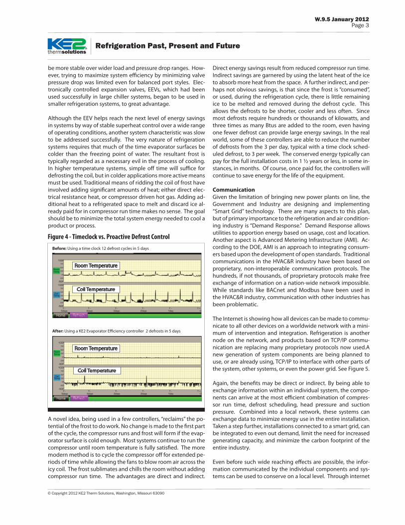
Direct energy savings result from reduced compressor run time. Indirect savings are garnered by using the latent heat of the ice to absorb more heat from the space. A further indirect, and per-haps not obvious savings, is that since the frost is “consumed”, or used, during the refrigeration cycle, there is little remaining ice to be melted and removed during the defrost cycle. This allows the defrosts to be shorter, cooler and less often. Since most defrosts require hundreds or thousands of kilowatts, and three times as many Btus are added to the room, even having one fewer defrost can provide large energy savings. In the real world, some of these controllers are able to reduce the number of defrosts from the 3 per day, typical with a time clock sched-uled defrost, to 3 per week. The conserved energy typically can pay for the full installation costs in 1 ½ years or less, in some in-stances, in months. Of course, once paid for, the controllers will continue to save energy for the life of the equipment.
CommunicationGiven the limitation of bringing new power plants on line, the Government and Industry are designing and implementing “Smart Grid” technology. There are many aspects to this plan, but of primary importance to the refrigeration and air condition-ing industry is “Demand Response.” Demand Response allows utilities to apportion energy based on usage, cost and location. Another aspect is Advanced Metering Infrastructure (AMI). Ac-cording to the DOE, AMI is an approach to integrating consum-ers based upon the development of open standards. Traditional communications in the HVAC&R industry have been based on proprietary, non-interoperable communication protocols. The hundreds, if not thousands, of proprietary protocols make free exchange of information on a nation-wide network impossible. While standards like BACnet and Modbus have been used in the HVAC&R industry, communication with other industries has been problematic.
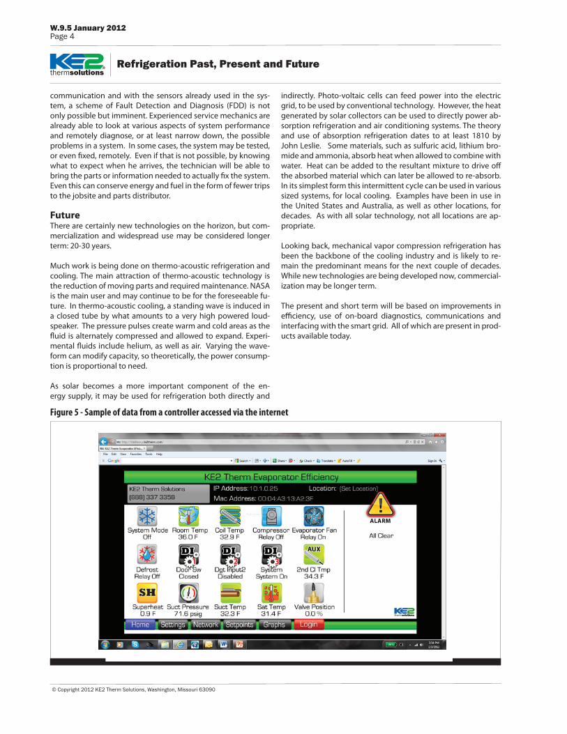
The Internet is showing how all devices can be made to commu-nicate to all other devices on a worldwide network with a mini-mum of intervention and integration. Refrigeration is another node on the network, and products based on TCP/IP commu-nication are replacing many proprietary protocols now used.A new generation of system components are being planned to use, or are already using, TCP/IP to interface with other parts of the system, other systems, or even the power grid. See Figure 5.
Again, the benefits may be direct or indirect. By being able to exchange information within an individual system, the compo-nents can arrive at the most efficient combination of compres-sor run time, defrost scheduling, head pressure and suction pressure. Combined into a local network, these systems can exchange data to minimize energy use in the entire installation.Taken a step further, installations connected to a smart grid, can be integrated to even out demand, limit the need for increased generating capacity, and minimize the carbon footprint of the entire industry.
Even before such wide reaching effects are possible, the infor-mation communicated by the individual components and sys-tems can be used to conserve on a local level. Through internet
be more stable over wider load and pressure drop ranges. How-ever, trying to maximize system efficiency by minimizing valve pressure drop was limited even for balanced port styles. Elec-tronically controlled expansion valves, EEVs, which had been used successfully in large chiller systems, began to be used in smaller refrigeration systems, to great advantage.
Although the EEV helps reach the next level of energy savings in systems by way of stable superheat control over a wide range of operating conditions, another system characteristic was slow to be addressed successfully. The very nature of refrigeration systems requires that much of the time evaporator surfaces be colder than the freezing point of water. The resultant frost is typically regarded as a necessary evil in the process of cooling. In higher temperature systems, simple off time will suffice for defrosting the coil, but in colder applications more active means must be used. Traditional means of ridding the coil of frost have involved adding significant amounts of heat; either direct elec-trical resistance heat, or compressor driven hot gas. Adding ad-ditional heat to a refrigerated space to melt and discard ice al-ready paid for in compressor run time makes no sense. The goal should be to minimize the total system energy needed to cool a product or process.
A novel idea, being used in a few controllers, “reclaims” the po-tential of the frost to do work. No change is made to the first part of the cycle, the compressor runs and frost will form if the evap-orator surface is cold enough. Most systems continue to run the compressor until room temperature is fully satisfied. The more modern method is to cycle the compressor off for extended pe-riods of time while allowing the fans to blow room air across the icy coil. The frost sublimates and chills the room without adding compressor run time. The advantages are direct and indirect.
Figure 4 - Timeclock vs. Proactive Defrost ControlBefore: Using a time clock 12 defrost cycles in 5 days
After: Using a KE2 Evaporator E�ciency controller 2 defrosts in 5 days
Room Temperature
Room Temperature
Coil Temperature
Coil Temperature
© Copyright 2012 KE2 Therm Solutions, Washington, Missouri 63090
Refrigeration Past, Present and Future
W.9.5 January 2012Page 4
thermsolutions
communication and with the sensors already used in the sys-tem, a scheme of Fault Detection and Diagnosis (FDD) is not only possible but imminent. Experienced service mechanics are already able to look at various aspects of system performance and remotely diagnose, or at least narrow down, the possible problems in a system. In some cases, the system may be tested, or even fixed, remotely. Even if that is not possible, by knowing what to expect when he arrives, the technician will be able to bring the parts or information needed to actually fix the system. Even this can conserve energy and fuel in the form of fewer trips to the jobsite and parts distributor.
FutureThere are certainly new technologies on the horizon, but com-mercialization and widespread use may be considered longer term: 20-30 years.
Much work is being done on thermo-acoustic refrigeration and cooling. The main attraction of thermo-acoustic technology is the reduction of moving parts and required maintenance. NASA is the main user and may continue to be for the foreseeable fu-ture. In thermo-acoustic cooling, a standing wave is induced in a closed tube by what amounts to a very high powered loud-speaker. The pressure pulses create warm and cold areas as the fluid is alternately compressed and allowed to expand. Experi-mental fluids include helium, as well as air. Varying the wave-form can modify capacity, so theoretically, the power consump-tion is proportional to need.
As solar becomes a more important component of the en-ergy supply, it may be used for refrigeration both directly and
indirectly. Photo-voltaic cells can feed power into the electric grid, to be used by conventional technology. However, the heat generated by solar collectors can be used to directly power ab-sorption refrigeration and air conditioning systems. The theory and use of absorption refrigeration dates to at least 1810 by John Leslie. Some materials, such as sulfuric acid, lithium bro-mide and ammonia, absorb heat when allowed to combine with water. Heat can be added to the resultant mixture to drive off the absorbed material which can later be allowed to re-absorb. In its simplest form this intermittent cycle can be used in various sized systems, for local cooling. Examples have been in use in the United States and Australia, as well as other locations, for decades. As with all solar technology, not all locations are ap-propriate.
Looking back, mechanical vapor compression refrigeration has been the backbone of the cooling industry and is likely to re-main the predominant means for the next couple of decades. While new technologies are being developed now, commercial-ization may be longer term.
The present and short term will be based on improvements in efficiency, use of on-board diagnostics, communications and interfacing with the smart grid. All of which are present in prod-ucts available today.
Figure 5 - Sample of data from a controller accessed via the internet