specification for hot-rolled structural steel sections...©kebs ks 572: 2017 3 kenya standard...
TRANSCRIPT

KENYA STANDARD KS 572: 2017
Specification for hot-rolled structural steel sections
No copying of this standard without KEBS permission except as permitted by copyright law

TECHNICAL COMMITTEE REPRESENTATION
The following organizations were represented on the Technical Committee: 1. Architectural association of Kenya 2. Blue Nile group of companies 3. Brollo Kenya Limited 4. Consumer Information Network 5. Dedan Kimathi University Of Technology\ 6. Devki Steel Mill Ltd 7. Doshi & co(H) Ltd 8. Howard Humphreys 9. Insteel Limited 10. Kenya Association of manufacturers 11. Kenya Institute of Research and development 12. Kenya National Accreditation Services 13. Nails and Steel Products 14. National Housing Corporation 15. Palak international limited 16. Steel Makers Ltd 17. Tononoka Steels 18. University of Nairobi 19. Kenya Bureau of Standards — Secretariat
REVISION OF KENYA STANDARDS
In order to keep abreast of progress in industry, Kenya Standards shall be regularly reviewed. Suggestions for improvements to published standards, addressed to the Managing Director, Kenya Bureau of Standards, are welcome.
© Kenya Bureau of Standards, 2017 Copyright. Users are reminded that by virtue of section 6 of the Copyright Act, Cap. 130 of the Laws of Kenya, copyright subsists in all Kenya Standards and except as provided under section 7 of this Act, no Kenya Standard produced by Kenya Bureau of Standards may be reproduced, stored in a retrieval system in any form or transmitted by any means without prior permission in writing from the Managing Director. Permission may be conditional on an appropriate royalty payment. Care should be taken to ensure that material used is from the current edition of the standard and that it is updated whenever the standard is amended or revised. The number and date of the standard should therefore be clearly identified. The use of material in print or in electronic form to be used commercially with or without payment or in commercial contracts is subject to payment of a royalty.

KENYA STANDARD KS 572: 2017
Specification for hot-rolled structural steel sections
KENYA BUREAU OF STANDARDS (KEBS)
Head Office: P.O. Box 54974, Nairobi-00200, Tel.: (+254 020) 605490, 602350, Fax: (+254 020) 604031 E-Mail: [email protected], Web:http://www.kebs.org
Coast Region Lake Region Rift Valley Region
P.O. Box 99376, Mombasa-80100 P.O. Box 2949, Kisumu-40100 P.O. Box 2138, Nakuru-20100
Tel.: (+254 041) 229563, 230939/40 Tel.: (+254 057) 23549, 22396 Tel.: (+254 051) 210553, 210555 Fax: (+254 041) 229448 Fax: (+254 057) 21814
KS 572: 2017 ©KEBS
2
Foreword This Kenya Standard was prepared by the Steel Technical Committee under the guidance of the Standards Projects Committee and it is in accordance with the procedures of the Kenya Bureau of Standards. The standard specifies the requirements of hot-rolled structural steel sections, which are currently rolled in Kenya. Hot-rolled structural steel sections are widely used in the construction of steel structures. It is hoped that this standard will control the variation in dimensions, chemical composition and, hence, the strength of these sections. The standard has excluded sections of imperial sizes or direct metric conversions as these sizes will be discarded with the adoption of fully metric sizes. In preparing this standard, reference was made to the following International Standards and other sources which are highly acknowledged with thanks:
ISO 657 — Dimensions of hot-rolled steel sections. ISO 1035 — Dimensions of hot-rolled flat bars.

©KEBS KS 572: 2017
3
KENYA STANDARD
Specification for hot-rolled structural steel sections 1. Scope
This Kenya Standard specifies the requirements for nominal dimensions, mass and basic sectional properties of hot-rolled structural steel sections. It also lays down rolling and cutting tolerances. The sections covered include the following:
(i) Equal angles
(ii) Unequal angles
(iii) Channels
(iv) Flats.
2. Definitions
For the purpose of this standard, the following definitions shall apply: 2.1 longitudinal direction the direction of the greatest extension of the steel during rolling 2.2 transverse direction the direction at right angles to the direction of the greatest extension of the steel during rolling 2.3 t section his is a rolled finished product of solid section of special profile 2.4 flat a solid rectangular cross-section with edges of controlled profile and of thickness greater than or equal to 3 mm, width less than 600 mm and supplied in straight length 2.5 bundle two or more similar sections of the same size and material properly bound together 2.6 batch any quantity of similar sections of one size and material type in bundles presented for examination and test at any one time 2.7 test specimen a portion or a single item from a batch for the purpose of applying a particular test 2.8 test piece a prepared piece for testing, made from a test specimen by some mechanical operation 2.9
KS 572: 2017 ©KEBS
4
ultimate tensile stress or tensile strength the maximum load reached in a tensile test divided by the original cross-sectional area of the gauge length
portion of the test piece.
3. Nominal density and nominal mass
3.1 Nominal density — For the purpose of calculating mass, the density of hot-rolled steel shall be
taken as 7 850 kg/m3.
3.2 Nominal Mass — The nominal mass per metre length of sections is calculated on the basis of the nominal density in 3.1 multiplied by the cross-sectional area and as shown in Tables 11 – 14.
4. Steel making process
4.1 Method of manufacturing steel — The method of manufacturing steel, which shall be at the
option of the manufacturer, shall be disclosed if requested in the order. However, the steel so produced shall be in accordance with KS 02-18, Specification for steel for building and construction.
4.2 Freedom from defects — The rolled sections shall be free from pipe, harmful segregation, surface
flaws, foreign bodies, mill scales, which cannot be removed by manual wire brushing and other defects detrimental to their use.
5. Dimensions and tolerances
5.1 Dimensions and sectional properties — The dimensions and sectional properties of the
rolled sections shall be as specified in Tables 11 — 14.
note: The sizes of the toe radii are specified but the sectional properties have been calculated assuming a toe radius equal to half the root radius.
5.2 Tolerances on mass — The rolling tolerances on mass per unit length as measured on a sample
shall be ± 4per cent.
5.3 Dimensional tolerances
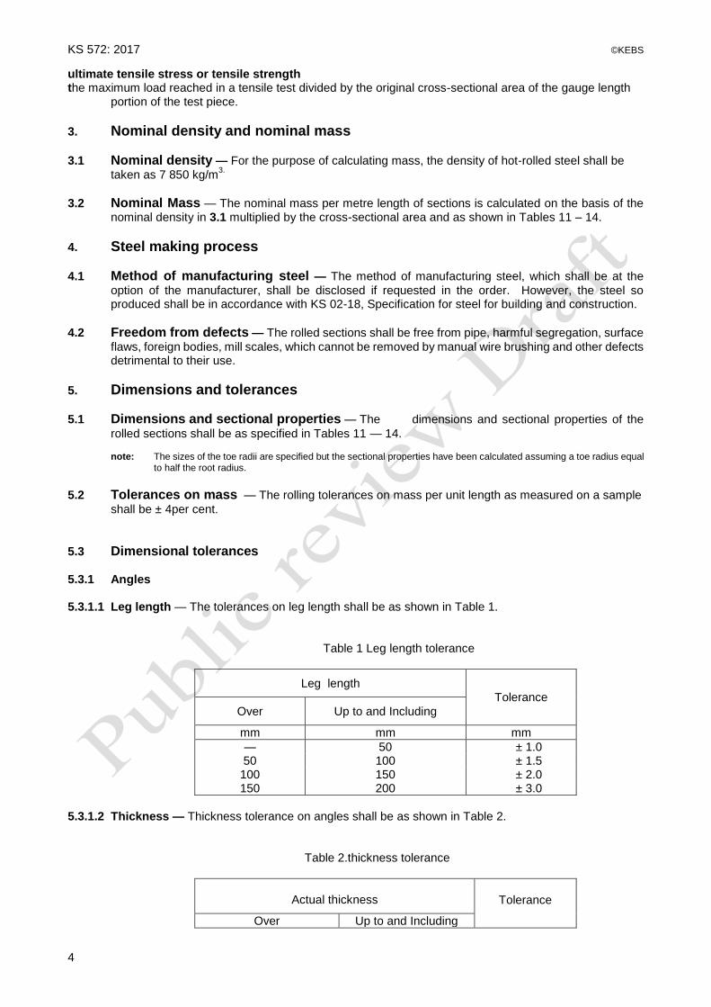
5.3.1 Angles 5.3.1.1 Leg length — The tolerances on leg length shall be as shown in Table 1.
Table 1 Leg length tolerance
Leg length
Tolerance
Over
Up to and Including
mm mm mm
— 50 ± 1.0 50 100 ± 1.5 100 150 ± 2.0 150 200 ± 3.0
5.3.1.2 Thickness — Thickness tolerance on angles shall be as shown in Table 2.
Table 2.thickness tolerance
Actual thickness
Tolerance
Over Up to and Including
©KEBS KS 572: 2017
5
mm mm mm
— 10 ± 0.5
10 15 ± 0.8
15 20 ± 1.0
20 — ± 1.2
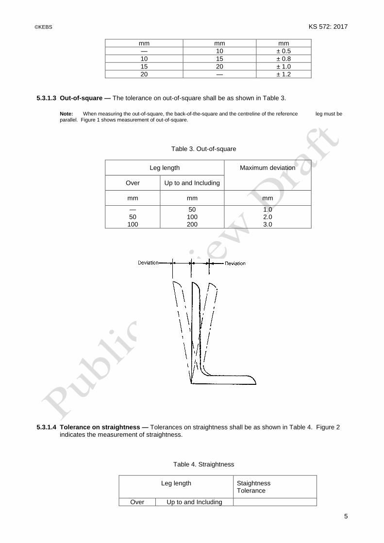
5.3.1.3 Out-of-square — The tolerance on out-of-square shall be as shown in Table 3.
Note: When measuring the out-of-square, the back-of-the-square and the centreline of the reference leg must be parallel. Figure 1 shows measurement of out-of-square.
Table 3. Out-of-square
Leg length
Maximum deviation
Over
Up to and Including
mm
mm
mm
— 50 1.0 50 100 2.0 100 200 3.0
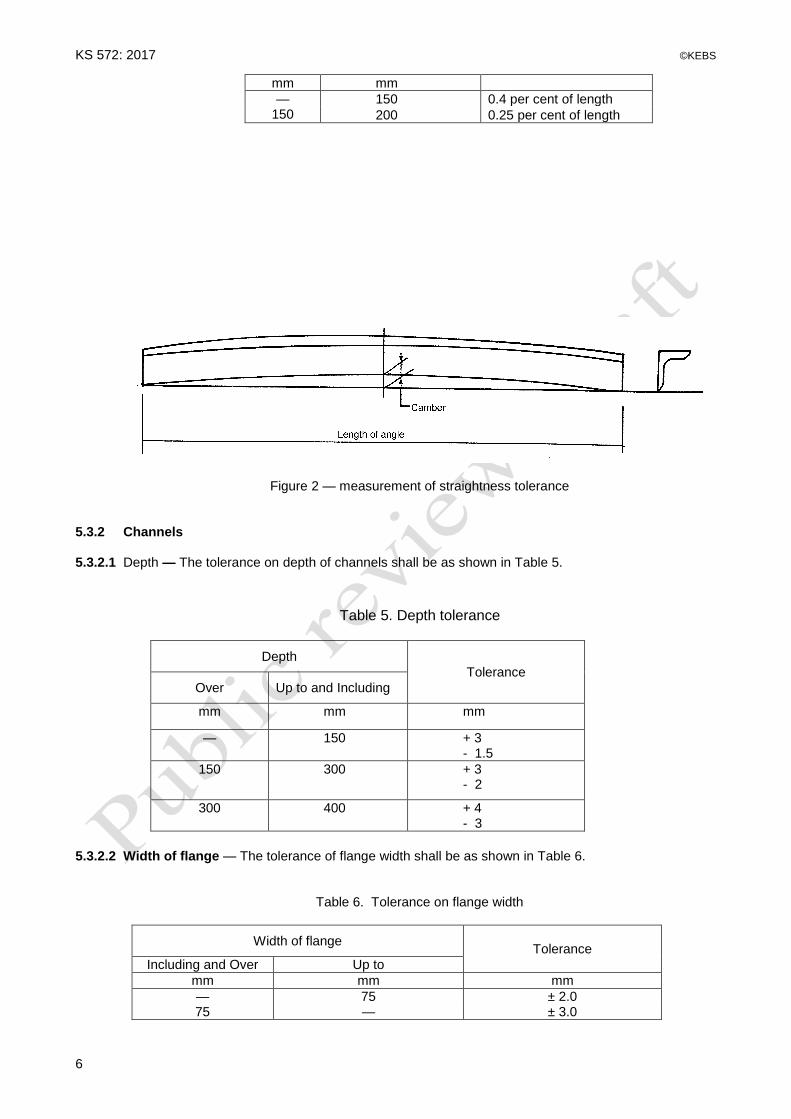
5.3.1.4 Tolerance on straightness — Tolerances on straightness shall be as shown in Table 4. Figure 2 indicates the measurement of straightness.
Table 4. Straightness
Leg length
Staightness Tolerance
Over Up to and Including
KS 572: 2017 ©KEBS
6
mm mm
— 150
150 0.4 per cent of length
200 0.25 per cent of length
Figure 2 — measurement of straightness tolerance
5.3.2 Channels 5.3.2.1 Depth — The tolerance on depth of channels shall be as shown in Table 5.
Table 5. Depth tolerance
Depth
Tolerance
Over
Up to and Including
mm mm mm
— 150 + 3 - 1.5
150 300 + 3 - 2
300 400 + 4 - 3
5.3.2.2 Width of flange — The tolerance of flange width shall be as shown in Table 6.
Table 6. Tolerance on flange width
Width of flange Tolerance
Including and Over Up to
mm mm mm
— 75 ± 2.0 75 — ± 3.0

©KEBS KS 572: 2017
7
5.3.2.3 Flange thickness — Tolerance on flange thickness shall be as shown in Table 7.
Table 7. Tolerance on flange thickness
Thickness of flange, T
Tolerance
Over Up to and Including
mm mm mm
— 9.0 - 0.5
9.0 15.0 - 1.0
15.0 17.0 - 1.5
5.3.2.4 Tolerance on thickness of web — Tolerance on thickness of all webs of channels shall be ± 0.5 mm. 5.3.2.5 Flange out-of-square — The flange of the channels shall be parallel within the tolerances specified in
Table 8 (see Figure 3).
Table 8. Flange out-of-square
WIDTH OF FLANGE
TOLERANCE (Max. Deviation)
Over
Up to and Including
mm mm mm
— 60 1.0 60 80 1.5 80 100 2.0
Figure 3 — flange out-of-square
5.3.2.6 Flatness of web — The tolerance on flatness of outer face of web of channel shall be as follows (see Figure 4)
Convexity ………………………………………… Not permitted Concavity ………………………………………… 15 per cent of nominal thickness of web.

KS 572: 2017 ©KEBS
8
Figure 4 — flatness of web of channels
5.3.3 Flats 5.3.3.1 Width — The tolerance on width of hot-rolled steel flats shall be in accordance with Table 9.
Table 9. Tolerance on width of flats
WIDTH
TOLERANCE
Over Up to and Including
mm mm mm
— 50 ± 1.0
50 75 ± 1.2
75 100 ± 1.5
100 125 ± 2.0
125 150 ± 2.5
5.3.3.2 Thickness — The tolerance on thickness of flats shall be in accordance with Table 10.
Table 10. Tolerance on thickness of flats
THICKNESS
TOLERANCE ON THICKNESS FOR WIDTH (b)

©KEBS KS 572: 2017
9
Over Up to and Including b < 50 50 < b < 150
mm mm mm mm
— 20 ± 0.5 ± 0.5
20 40 ± 0.8 ± 1.0
40 — — ± 1.5
5.4 Cutting Tolerance for Length — Sections shall be ordered and supplied either as ‘nominal’ or as
‘exact’ lengths. 5.4.1 Nominal Length —The sections shall be supplied in lengths of 12m,6 m and 3m and below . The
tolerance on nominal length shall be ± 0.4 per cent of that length.
5.4.2 Exact Length — When a section is to be cut to an exact length, it shall be supplied to within ± 0.08 per
cent of that length. 5.5 Straightness and twist — All sections leaving the factory shall be straight and free from twist and
adverse effects of weather.
6. Routine inspection and testing
6.1 All materials shall be subject to routine inspection and testing by the manufacturer or supplier in
accordance with 7 and 8 of this standard, and a record of the test results of materials complying with this standard shall be kept by the supplier in a form similar to that shown in Appendix A. The records shall be available for inspection by the purchaser or his representative on demand. In the case of a material delivered to a purchaser, the manufacturer shall supply a certificate containing the results of all the required tests on samples taken from the delivered material if requested by the purchaser.
6.2 Purchaser’s test 6.2.1 The purchaser may verify each batch of steel for compliance with the requirements for nominal mass,
dimensional tolerances and elongation. 6.2.2 If the purchaser wishes to verify that the specified characteristic strength (8.5.2) is attained by a batch
of steel of 35 000 kg or less, 10 sections shall be chosen at random from the batch and a tensile test specimen cut from each section. These test specimens shall be tested to confirm that all sections meet the requirements for the specified section size. So long as all the test specimens meet this specification then the test specimens shall undergo tensile testing. If one or more test results are less than 0.93 of the specified characteristic strength, then the batch shall be deemed not to comply with the requirements of this standard.
7. Selection of test samples
7.1 Test samples of sufficient length for the specified tests shall be selected from each batch at a
frequency not less than one sample from each 25 000 kg, except that if a batch comprises sections less than the quantity specified, at least one test sample shall be selected to represent a day’s production.
7.2 Manufacturers shall identify the sections as belonging to a particular batch with a suitable marker or
identification in a manner that the sections can be traced to the cast from which they are rolled. In such a case, the purchaser’s test of sections specified under 6.2.2 shall be on the basis of batch so identified.
8. Tensile test 8.1 The tensile test shall be carried out in accordance with ISO 6892 - 1, Methods for tensile testing of
metals.

KS 572: 2017 ©KEBS
10
8.2 Tensile Test Piece — The test piece shall consist of a strip taken from 1 metre test specimen. The strip shall be taken longitudinally at any point of the section for flats and angles but along the web for channels. The strip shall comply with the following conditions:
(i) sides of test piece shall be parallel within a maximum variation along parallel length of ± 0.2
per cent of nominal width.
(ii) The trimmed ends and parallel length of test piece shall be coaxial.
(iii) Nominal gauge length Lo = 5.65 So
where So = the original cross-sectional area of the test piece. Lo shall be within ± 5 per cent of the nominal values.
(iv) Minimum parallel length Lp = Lo + 2 nominal widths.
(v) The width of the test piece shall be not less than 6 mm.
(vi) The test piece shall not be flattened between the gauge marks except for the purpose of gripping the test piece in a test machine.
8.3 Rate of Loading — The rate of loading when approaching the yield stress shall not exceed 10 N/mm
2
per second.
8.4 Yield stress 8.4.1 For routine testing the yield stress shall be taken as the stress at which elongation first occurs in the
test piece without increasing the load during tensile test. In the case of steels with no such definite yield point, the proof stress is the stress under the prescribed testing conditions at which the observed increase in the gauge length is 0.5 per cent of the gauge length when the rate at which the load applied is not more than 10 N/mm
2 per second.
8.4.2 The stresses shall be calculated using the original cross-sectional area of the gauge length portion of
the specimen.
8.5 Specified characteristic strength 8.5.1 The specified characteristic strength of the steel is the value of yield stress determined in accordance
with 7.1 of this standard, below which shall fall not more than 5 per cent of the test results. 8.5.2 The specified characteristic strength of the mild steel shall be 250 N/mm
2.
8.5.3 When one or more test results is less than 93 per cent of the specified characteristic strength, then the
batch shall be deemed not to comply with the requirements of this Kenya Standard. 8.6 Tensile Strength — The ultimate tensile strength shall be at least 15 per cent greater than the yield
stress measured in the tensile test.
8.7 Minimum Elongation — The minimum elongation on gauge length of the steel complying with this
standard shall be 22 per cent.
9. Chemical composition The chemical composition shall be in accordance to table 1 of KS 18.
10. Defects revealed after delivery
Should any or all material after delivery be found not to be in accordance with this specification, such material shall be deemed not to comply with this Kenya Standard. However, notwithstanding any previous acceptance, materials delivered, which does not comply with this standard due to bad

©KEBS KS 572: 2017
11
bending, chemical exposure, heating etc. while on transit or on site shall not be cause for manufacturer’s liability.
11. Marking
Each piece for despatch shall be indelibly and legibly marked with the following particulars:
i. Manufacturer’s name or trade mark. ii. Designation of section. iii. Length of the section.
Figure 5 — dimensions and principal axes of equal angle section

©KEBS KS 572: 1986
12
Table 11. Equal angles (see figure 5)
DESIGNATION
LE
G LE
NG
TH
B
TH
ICK
NE
SS
t
RADIUS
MA
SS
/UN
IT
LE
NG
TH
AR
EA
OF
SE
CT
ION
DIS
TA
NC
E O
F
CE
NT
RE
OF
GR
AV
ITY
C
SECOND MOMENT OF AREA
RADIUS OF GYRATION
ELASTIC MODULES
Siz
e
Th
ickness Root
r1 Toe r2
About X-X Y-Y
About U-U
About V-V
About X-X Y-Y
About U-U
About V-V
About X-X Y-Y
mm mm mm mm mm mm kg/m cm2 cm cm
4 cm
4 cm cm cm cm cm
3
20x20 3 20 3 3.5 2.4 0.88 1.12 0.60 0.39 0.61 0.16 0.59 0.74 0.38 0.28
20x20 4 20 4 3.5 2.4 0.14 1.45 0.64 0.49 0.77 0.21 0.58 0.73 0.38 0.36
25x25 3 25 3 3.5 2.4 1.11 1.42 0.72 0.80 1.26 0.33 0.75 0.94 0.48 0.45
25x25 4 25 4 3.5 2.4 1.45 1.85 0.76 1.01 1.60 0.43 0.74 0.93 0.48 0.58
25x25 6 25 6 3.5 2.4 2.08 2.65 0.84 1.38 2.15 0.61 0.72 0.90 0.48 0.83
30x30 3 30 3 5 2.4 1.36 1.74 0.84 0.40 2.23 0.58 0.90 1.13 0.58 0.65
30x30 4 30 4 5 2.4 1.78 2.27 0.88 1.80 2.85 0.75 0.89 1.12 0.58 0.85
30 x 30 6 30 6 5 2.4 2.54 3.24 0.97 2.55 0.89
40x40 3 40 3 6 2.4 1.84 2.35 1.07 3.45 5.46 1.44 1.21 1.52 0.78 1.18
40x40 4 40 4 6 2.4 2.42 3.08 1.12 4.47 7.09 1.85 1.21 1.53 0.78 1.55
40x40 6 40 6 6 2.4 3.52 4.48 1.20 6.31 9.89 2.65 1.19 1.49 0.77 2.26
50x50 3 50 3 7 2.4 2.33 2.96 1.31 6.86 10.8 2.88 1.52 1.91 0.99 1.86
50x50 4 50 4 7 2.4 3.06 3.89 1.36 8.97 14.2 3.72 1.52 1.91 0.98 2.46
50x50 5 50 5 7 2.4 3.77 4.80 1.40 11.0 17.4 4.54 1.51 1.90 0.97 3.05
50x50 6 50 6 7 2.4 4.77 5.69 1.45 12.8 20.4 5.33 1.50 1.89 0.97 3.61
50x50 8 50 8 7 2.4 5.82 7.41 1.52 16.3 25.7 6.87 1.48 1.86 0.96 4.68
TABLE 11. EQUAL ANGLES (contd.) (see FIGURE 5)
DESIGNATION
LE
G
LE
NG
TH
B
TH
ICK
NE
SS
t
RADIUS
MA
SS
/UN
IT
LE
NG
TH
AR
EA
Of
SE
CT
ION
DIS
TA
NC
E O
F
CE
NT
RE
OF
GR
AV
ITY
C
SECOND MOMENT OF AREA
RADIUS OF GYRATION
ELASTIC MODULUS
Siz
e
Thic
kness Root
r1 Toe r2
About X-X Y-Y
About U-U
About V-V
About X-X Y-Y
About U-U
About V-V
About X-X Y-Y

©KEBS KS 572: 1986
13
mm mm mm mm mm mm kg/m cm2 cm cm
4 cm
4 cm
4 cm cm cm cm
3
60x60 5 60 5 8 2.4 4.57 5.82 1.64 19.4 30.7 8.02 1.82 2.30 1.17 4.45
60x60 6 60 6 8 2.4 5.42 6.91 1.69 22.8 36.2 9.43 1.82 2.29 1.17 5.29
60x60 8 60 8 8 2.4 7.09 9.03 1.77 29.2 46.2 12.1 1.80 2.26 1.16 6.89
60x60 10 60 10 8 2.4 8.69 11.1 1.85 34.9 55.1 14.8 1.78 2.23 1.16 8.41
65x65 5 65 5 8 2.4 4.90 6.25 1.77 24.7 39.4 9.9 1.99 2.51 1.26 5.2
65x65 6 65 6 8 2.4 5.80 7.44 1.81 29.1 46.5 11.7 1.98 2.50 1.26 6.2
65x65 8 65 8 8 2.4 7.70 9.76 1.89 37.4 59.5 15.3 1.96 2.47 1.25 8.1
65x65 10 65 10 8 2.4 9.40 12.00 1.97 45.0 71.3 10.8 1.94 2.44 1.25 9.9
70x70 5 70 5 9 2.4 5.37 6.84 1.88 31.3 49.5 13.0 2.14 2.69 1.38 6.11
70x70 6 70 6 9 2.4 6.38 8.13 1.93 36.9 58.5 15.2 2.13 2.68 1.37 7.27
70x70 8 70 8 9 2.4 8.36 10.6 2.01 47.5 75.5 19.7 2.11 2.66 1.36 9.52
70x70 10 70 10 9 2.4 10.30 13.1 2.09 57.2 90.5 23.9 2.09 2.63 1.35 11.7
75x75 6 75 6 9 2.4 6.8 8.66 2.06 45.7 73.1 18.4 2.30 2.91 1.46 8.4
75x75 8 75 8 9 2.4 8.9 11.38 2.14 59.0 94.1 24.0 2.28 2.88 1.45 11.0
75x75 10 75 10 9 2.4 11.0 14.02 2.22 71.4 113.3 29.4 2.26 2.84 1.45 13.5
75x75 12 75 12 9 2.4 13.07 16.65 2.29 82.8 132.3 32.3 2.23 2.82 1.39 15.9
80x80 6 80 6 10 4.8 7.34 9.35 2.17 55.8 88.5 23.1 2.44 3.08 1.57 9.57
80x80 8 80 8 10 4.8 9.63 12.3 2.26 72.2 115 29.8 2.43 3.06 1.56 12.6
80x80 10 80 10 10 4.8 11.90 15.1 2.34 87.5 139 36.3 2.41 3.03 1.55 15.d4
80x80 12 80 12 10 4.8 14.0 17.9 2.41 102 161 42.7 2.39 3.00 1.55 18.2
90x90 6 90 6 11 4.8 8.30 10.6 2.41 80.3 127 33.3 2.76 3.47 1.78 12.2
90x90 8 90 8 11 4.8 10.9 13.9 2.50 104 166 43.1 2.74 3.45 1.76 16.1
90x90 10 90 10 11 4.8 13.4 17.1 2.58 127 201 52.8 2.72 3.42 1.76 19.8
90x90 12 90 12 11 4.8 15.9 20.3 2.66 148 234 62.0 2.70 3.40 1.75 23.3
100x100 8 100 8 12 4.8 12.2 15.5 2.74 145 230 59.8 3.06 3.85 1.96 19.9
100x100 10 100 10 12 4.8 15.0 19.2 2.82 177 280 72.9 3.04 3.83 1.95 24.6
100x100 12 100 12 12 4.8 17.8 22.7 2.90 207 328 85.7 3.02 3.80 1.94 29.1
100x100 15 100 15 12 4.8 21.9 27.9 3.02 249 393 104 2.98 3.75 1.93 35.6
TABLE 11. EQUAL ANGLES (contd.) (see FIGURE 5)
DESIGNATION
LE
G
Leng
th
B
thic
kness
t
RADIUS
MA
SS
/UN
IT
LE
NG
TH
AR
EA
OF
SE
CT
ION
DIS
TA
NC
E O
F
CE
NT
RE
OF
GR
AV
ITY
SECOND MOMENT OF AREA
RADIUS OF GYRATION
ELASTIC MODULUS
Siz
e
Thic
kness
Root r2
Toe r2
About X-X Y-Y
About U-U
About V-V
About X-X Y-Y
About U-U
About V-V
About X-X Y-Y
mm mm mm mm mm mm kg/m cm2 cm cm
4 cm
4 cm
4 cm cm cm cm
2

KS 572: 1986 ©KEBS
14
120x120 8 120 8 13 4.8 14.7 18.7 3.23 255 405 105 3.69 4.65 2.37 29.1
120x120 10 120 10 13 4.8 18.2 23.2 3.31 313 497 129 3.76 4.63 2.36 36.0
120x120 12 120 12 13 4.8 21.6 27.5 3.40 368 584 151 3.65 4.60 2.35 42.7
120x120 15 120 15 13 4.8 26.6 33.9 3.51 455 705 185 3.62 4.56 2.33 52.4
150x150 10 150 10 16 4.8 23.0 29.0 29.3 4.03 624 991 4.62 5.82 2.97 56.9
150x150 12 150 12 16 4.8 27.3 34.8 4.12 737 1 170 303 4.60 5.80 2.95 67.7
150x150 15 150 15 16 4.8 33.8 43.0 4.25 898 1 430 370 4.57 5.76 2.93 83.5
150x150 18 150 18 16 4.8 40.0 51.0 4.37 1 050 1 670 435 4.54 5.71 2.92 98.7
180x180 15 180 15 18 4.8 40.9 52.1 4.98 1 590 2 520 653 5.52 6.96 3.54 122
180x180 18 180 18 18 4.8 48.6 61.9 5.10 1 870 2 960 768 5.49 6.92 3.52 145
180x180 20 180 20 18 4.8 53.7 68.3 5.18 2 040 3 240 843 5.47 6.89 3.51 159
200x200 16 200 16 18 4.8 48.5 61.8 5.52 2 340 3 720 959 6.16 7.76 3.94 162
200x200 18 200 18 18 4.8 54.2 69.1 5.60 2 600 4 130 1 070 6.13 7.73 3.93 181
200x200 20 200 20 18 4.8 59.9 76.3 5.68 2 850 4 530 1 170 6.11 7.70 3.92 199
200x200 24 200 24 18 4.8 71.1 90.6 5.84 3 330 5 280 1 380 6.06 7.64 3.90 235
©KEBS KS 572: 1986
15
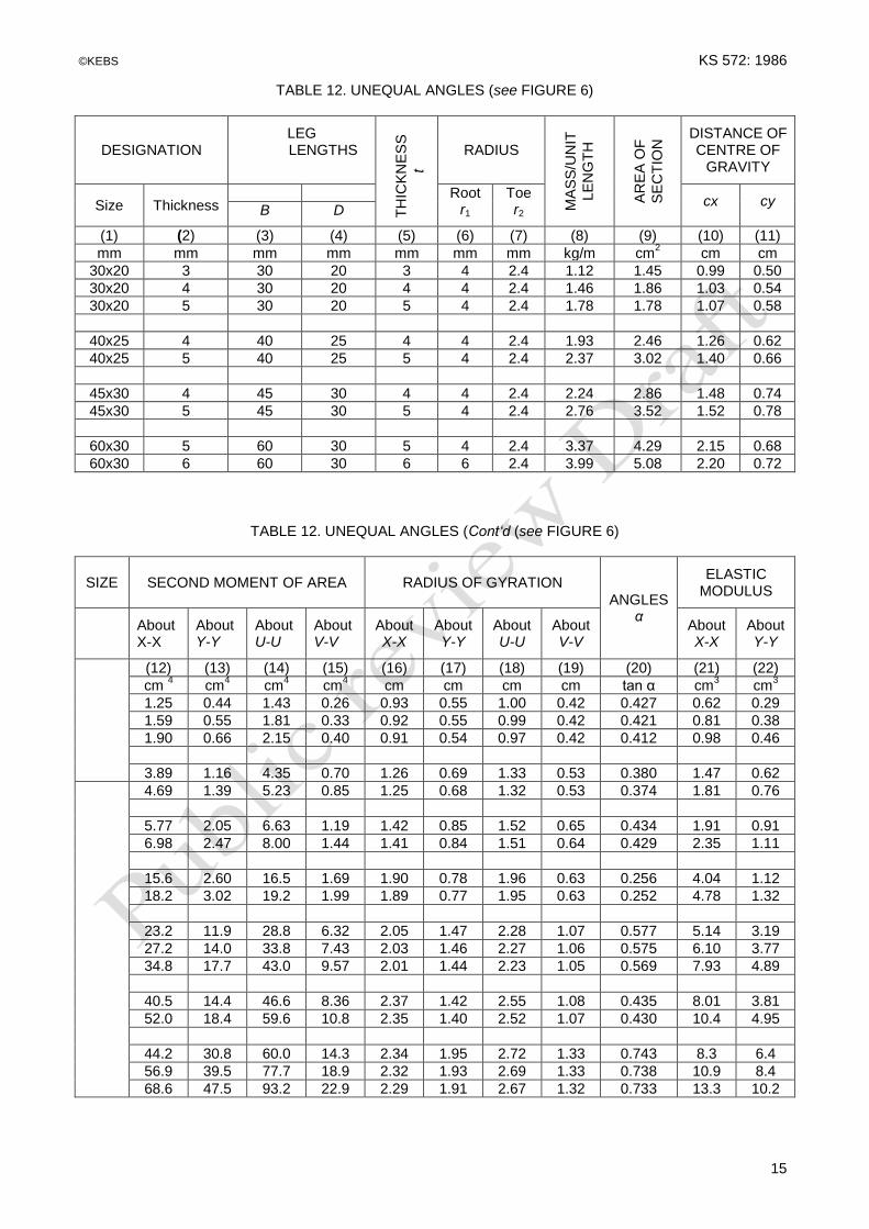
TABLE 12. UNEQUAL ANGLES (see FIGURE 6)
DESIGNATION
LEG LENGTHS
TH
ICK
NE
SS
t
RADIUS
MA
SS
/UN
IT
LE
NG
TH
AR
EA
OF
SE
CT
ION
DISTANCE OF CENTRE OF
GRAVITY
Size Thickness Root
r1 Toe r2
cx
cy B D
(1) (2) (3) (4) (5) (6) (7) (8) (9) (10) (11)
mm mm mm mm mm mm mm kg/m cm2 cm cm
30x20 3 30 20 3 4 2.4 1.12 1.45 0.99 0.50
30x20 4 30 20 4 4 2.4 1.46 1.86 1.03 0.54
30x20 5 30 20 5 4 2.4 1.78 1.78 1.07 0.58
40x25 4 40 25 4 4 2.4 1.93 2.46 1.26 0.62
40x25 5 40 25 5 4 2.4 2.37 3.02 1.40 0.66
45x30 4 45 30 4 4 2.4 2.24 2.86 1.48 0.74
45x30 5 45 30 5 4 2.4 2.76 3.52 1.52 0.78
60x30 5 60 30 5 4 2.4 3.37 4.29 2.15 0.68
60x30 6 60 30 6 6 2.4 3.99 5.08 2.20 0.72
TABLE 12. UNEQUAL ANGLES (Cont‘d (see FIGURE 6)
SIZE
SECOND MOMENT OF AREA
RADIUS OF GYRATION
ANGLES α
ELASTIC MODULUS
About X-X
About Y-Y
About U-U
About V-V
About X-X
About Y-Y
About U-U
About V-V
About X-X
About Y-Y
(12) (13) (14) (15) (16) (17) (18) (19) (20) (21) (22)
cm 4 cm
4 cm
4 cm
4 cm cm cm cm tan α cm
3 cm
3
1.25 0.44 1.43 0.26 0.93 0.55 1.00 0.42 0.427 0.62 0.29
1.59 0.55 1.81 0.33 0.92 0.55 0.99 0.42 0.421 0.81 0.38
1.90 0.66 2.15 0.40 0.91 0.54 0.97 0.42 0.412 0.98 0.46
3.89 1.16 4.35 0.70 1.26 0.69 1.33 0.53 0.380 1.47 0.62
4.69 1.39 5.23 0.85 1.25 0.68 1.32 0.53 0.374 1.81 0.76
5.77 2.05 6.63 1.19 1.42 0.85 1.52 0.65 0.434 1.91 0.91
6.98 2.47 8.00 1.44 1.41 0.84 1.51 0.64 0.429 2.35 1.11
15.6 2.60 16.5 1.69 1.90 0.78 1.96 0.63 0.256 4.04 1.12
18.2 3.02 19.2 1.99 1.89 0.77 1.95 0.63 0.252 4.78 1.32
23.2 11.9 28.8 6.32 2.05 1.47 2.28 1.07 0.577 5.14 3.19
27.2 14.0 33.8 7.43 2.03 1.46 2.27 1.06 0.575 6.10 3.77
34.8 17.7 43.0 9.57 2.01 1.44 2.23 1.05 0.569 7.93 4.89
40.5 14.4 46.6 8.36 2.37 1.42 2.55 1.08 0.435 8.01 3.81
52.0 18.4 59.6 10.8 2.35 1.40 2.52 1.07 0.430 10.4 4.95
44.2 30.8 60.0 14.3 2.34 1.95 2.72 1.33 0.743 8.3 6.4
56.9 39.5 77.7 18.9 2.32 1.93 2.69 1.33 0.738 10.9 8.4
68.6 47.5 93.2 22.9 2.29 1.91 2.67 1.32 0.733 13.3 10.2

KS 572: 1986 ©KEBS
16
TABLE 12. UNEQUAL ANGLES (cont’d.) (SEE FIGURE 6)
DESIGNATION
LEG LENGTHS
TH
ICK
NE
SS
t
RADIUS
MA
SS
/UN
IT
LE
NG
TH
AR
EA
OF
SE
CT
ION
DISTANCE OF CENTRE OF
GRAVITY
Size Thickness B D Root r1
Toe r2
cx cy
(1) (2) (3) (4) (5) (6) (7) (8) (9) (10) (11)
mm mm mm mm mm mm mm kg/m cm2 cm Cm
65x50 5 65 50 5 6 2.7 4.35 5.54 1.99 1.25
65x50 6 65 50 6 6 2.7 5.16 6.58 2.04 1.29
65x50 7 65 50 8 6 2.7 6.75 8.60 2.11 1.37
75x50 6 75 50 6 7 2.7 5.65 7.19 2.44 1.21
75x50 8 75 50 8 7 2.7 7.39 9.41 2.52 1.29
75x65 6 75 65 6 7 2.7 6.35 8.09 2.20 1.71
75x65 8 75 65 8 7 2.7 8.33 10.61 2.28 1.79
75x65 10 75 65 10 7 2.7 10.25 13.05 2.36 1.86
80x60 6 80 60 6 8 4.8 6.37 8.11 2.47 1.40
80x60 8 80 60 8 8 4.8 8.34 10.6 2.55 1.56
100x65 7 100 65 7 10 4.8 8.77 11.2 3.23 1.51
100x65 8 100 65 8 10 4.8 9.94 12.7 3.27 1.55
100x65 10 100 65 10 10 4.8 12.3 15.6 3.36 1.63
100x75 8 100 75 8 10 4.8 10.6 13.5 3.10 1.87
100x75 10 100 75 10 10 4.8 13.0 16.6 3.19 1.95
100x75 12 100 75 12 10 4.8 15.4 19.7 3.27 2.03
125x75 8 125 75 8 11 4.8 12.2 15.5 4.14 1.68
125x75 10 125 75 10 11 4.8 15.0 19.1 4.23 1.76
125x75 12 125 75 12 11 4.8 17.8 22.7 4.31 1.84
TABLE 12. UNEQUAL ANGLES (Cont’d) (see FIGURE 6)
SECOND MOMENT OF AREA
RADIUS OF GYRATION
ANGLE α
ELASTIC MODULUS
SIZE About X-X
About Y-Y
About U-U
About V-V
About X-X
About Y-Y
About U-U
About V-V
About X-X
About Y-Y
(12) (13) (14) (15) (16) (17) (18) (19) (20) (21) (22)
mm cm4 cm
4 cm
4 cm
4 cm cm cm cm tan α cm
3 cm
3
51.4 24.8 62.8 13.4 2.52 1.75 2.78 1.29 0.547 9.29 5.49
66.3 31.8 80.8 17.3 2.50 1.73 2.76 1.28 0.544 12.2 7.16
113 37.6 128 22.0 3.17 1.83 3.39 1.40 0.415 16.6 7.53
127 42.2 144 24.8 3.16 1.83 3.37 1.40 0.414 18.9 8.54
154 51.0 175 30.1 3.14 1.81 3.35 1.39 0.410 23.2 10.5
133 64.1 163 34.6 3.14 2.18 3.47 1.60 0.547 19.3 11.4
162 77.6 197 42.1 3.12 2.16 3.45 1.59 0.544 23.8 14.0
189 90.2 230 49.5 3.10 2.14 3.32 1.59 0.540 28.0 16.5
247 67.6 274 41.1 4.00 2.09 4.20 1.63 0.356 36.5 14.3
302 82.1 334 50.0 3.97 2.07 4.18 1.62 0.356 36.5 14.3
354 95.5 391 58.8 3.95 2.05 4.15 1.61 0.353 43.2 16.9
©KEBS KS 572: 1986
17
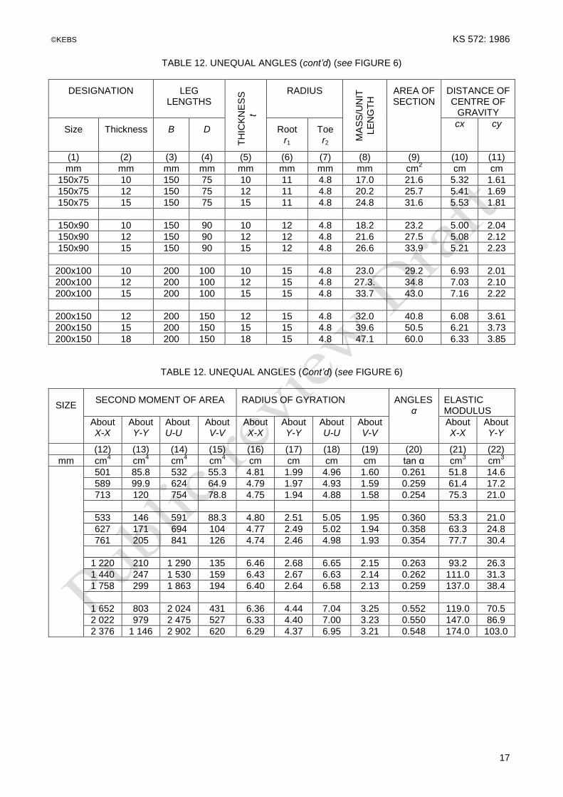
TABLE 12. UNEQUAL ANGLES (cont’d) (see FIGURE 6)
DESIGNATION
LEG LENGTHS
TH
ICK
NE
SS
t
RADIUS
MA
SS
/UN
IT
LE
NG
TH
AREA OF SECTION
DISTANCE OF CENTRE OF
GRAVITY
Size
Thickness
B
D
Root r1
Toe r2
cx cy
(1) (2) (3) (4) (5) (6) (7) (8) (9) (10) (11)
mm mm mm mm mm mm mm mm cm2 cm cm
150x75 10 150 75 10 11 4.8 17.0 21.6 5.32 1.61
150x75 12 150 75 12 11 4.8 20.2 25.7 5.41 1.69
150x75 15 150 75 15 11 4.8 24.8 31.6 5.53 1.81
150x90 10 150 90 10 12 4.8 18.2 23.2 5.00 2.04
150x90 12 150 90 12 12 4.8 21.6 27.5 5.08 2.12
150x90 15 150 90 15 12 4.8 26.6 33.9 5.21 2.23
200x100 10 200 100 10 15 4.8 23.0 29.2 6.93 2.01
200x100 12 200 100 12 15 4.8 27.3. 34.8 7.03 2.10
200x100 15 200 100 15 15 4.8 33.7 43.0 7.16 2.22
200x150 12 200 150 12 15 4.8 32.0 40.8 6.08 3.61
200x150 15 200 150 15 15 4.8 39.6 50.5 6.21 3.73
200x150 18 200 150 18 15 4.8 47.1 60.0 6.33 3.85
TABLE 12. UNEQUAL ANGLES (Cont’d) (see FIGURE 6)
SIZE
SECOND MOMENT OF AREA
RADIUS OF GYRATION
ANGLES α
ELASTIC MODULUS
About X-X
About Y-Y
About U-U
About V-V
About X-X
About Y-Y
About U-U
About V-V
About X-X
About Y-Y
(12) (13) (14) (15) (16) (17) (18) (19) (20) (21) (22)
mm cm4 cm
4 cm
4 cm
4 cm cm cm cm tan α cm
3 cm
3
501 85.8 532 55.3 4.81 1.99 4.96 1.60 0.261 51.8 14.6
589 99.9 624 64.9 4.79 1.97 4.93 1.59 0.259 61.4 17.2
713 120 754 78.8 4.75 1.94 4.88 1.58 0.254 75.3 21.0
533 146 591 88.3 4.80 2.51 5.05 1.95 0.360 53.3 21.0
627 171 694 104 4.77 2.49 5.02 1.94 0.358 63.3 24.8
761 205 841 126 4.74 2.46 4.98 1.93 0.354 77.7 30.4
1 220 210 1 290 135 6.46 2.68 6.65 2.15 0.263 93.2 26.3
1 440 247 1 530 159 6.43 2.67 6.63 2.14 0.262 111.0 31.3
1 758 299 1 863 194 6.40 2.64 6.58 2.13 0.259 137.0 38.4
1 652 803 2 024 431 6.36 4.44 7.04 3.25 0.552 119.0 70.5
2 022 979 2 475 527 6.33 4.40 7.00 3.23 0.550 147.0 86.9
2 376 1 146 2 902 620 6.29 4.37 6.95 3.21 0.548 174.0 103.0

KS 572: 1986 ©KEBS
18
©KEBS KS 572: 1986 s
19
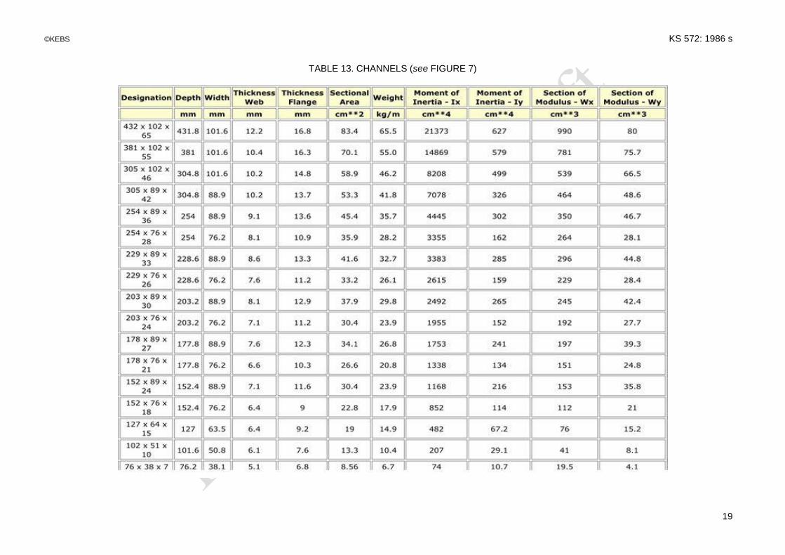
TABLE 13. CHANNELS (see FIGURE 7)

KS 572: 2017 ©KEBS
20
TABLE 13. CHANNELS (Cont’d) (see FIGURE 7)
DEPTH BETWEEN FILLETS
d
CENTROID
Cy
SECOND MOMENT OF AREA
RADIUS OF GYRATION
ELASTIC MODULUS
RATIO D/T
About X-X
About Y-Y
About X-X
About Y-Y
About X-X
About Y-Y
(10) (11) (12) (13) (14) (15) (16) (17) (18)
mm cm cm4 cm
4 cm cm cm
3 cm
3
47.4 1.43 102 18.0 3.12 1.30 25.6 5.85 10.7
66.1 1.51 200 27.2 3.91 1.44 40.0 7.77 12.5
84.7 1.60 350 39.5 4.68 1.57 58.4 10.1 14.1
101.6 1..68 570 55.3 5.45 1.67 81.4 12.8 15.6
119.2 1.81 900 79.0 6.22 1.81 113 16.8 16.0
136.0 1.90 1 320 105 6.98 1.94 147 20.6 17.1
150.0 2.02 1 930 142 7.75 2.10 193 26.0 17.4
168.7 2.11 1 640 183 8.50 2.23 240 31.0 18.3
193.6 2.20 4 000 240 9.63 2.36 320 38.2 19.2
235.8 2.60 7 800 452 11.6 2.80 520 61.1 20.0
282.0 2.48 11 900 492 13.4 2.74 678 66.3 21.9
328.2 2.38 17 200 541 15.2 2.68 858 71.0 23.5
KS 572: 2017 ©KEBS
21
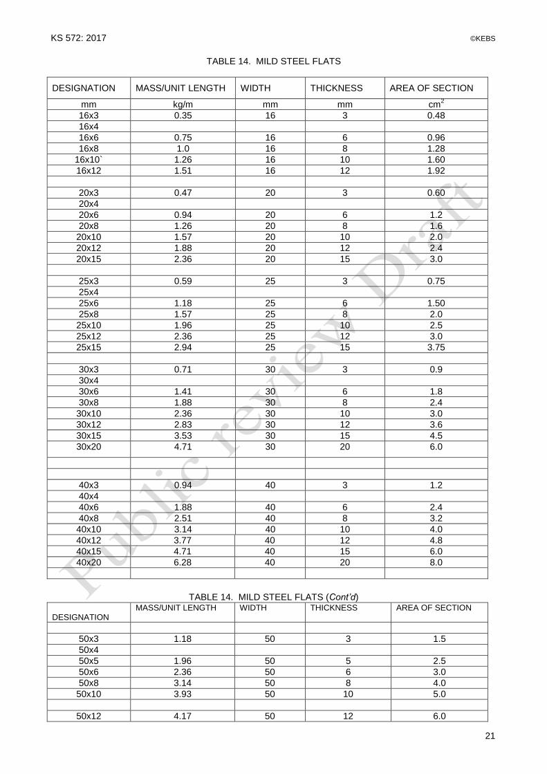
TABLE 14. MILD STEEL FLATS
DESIGNATION
MASS/UNIT LENGTH
WIDTH
THICKNESS
AREA OF SECTION
mm kg/m mm mm cm2
16x3 0.35 16 3 0.48
16x4
16x6 0.75 16 6 0.96
16x8 1.0 16 8 1.28
16x10` 1.26 16 10 1.60
16x12 1.51 16 12 1.92
20x3 0.47 20 3 0.60
20x4
20x6 0.94 20 6 1.2
20x8 1.26 20 8 1.6
20x10 1.57 20 10 2.0
20x12 1.88 20 12 2.4
20x15 2.36 20 15 3.0
25x3 0.59 25 3 0.75
25x4
25x6 1.18 25 6 1.50
25x8 1.57 25 8 2.0
25x10 1.96 25 10 2.5
25x12 2.36 25 12 3.0
25x15 2.94 25 15 3.75
30x3 0.71 30 3 0.9
30x4
30x6 1.41 30 6 1.8
30x8 1.88 30 8 2.4
30x10 2.36 30 10 3.0
30x12 2.83 30 12 3.6
30x15 3.53 30 15 4.5
30x20 4.71 30 20 6.0
40x3 0.94 40 3 1.2
40x4
40x6 1.88 40 6 2.4
40x8 2.51 40 8 3.2
40x10 3.14 40 10 4.0
40x12 3.77 40 12 4.8
40x15 4.71 40 15 6.0
40x20 6.28 40 20 8.0
TABLE 14. MILD STEEL FLATS (Cont’d)
DESIGNATION
MASS/UNIT LENGTH WIDTH THICKNESS AREA OF SECTION
50x3 1.18 50 3 1.5
50x4
50x5 1.96 50 5 2.5
50x6 2.36 50 6 3.0
50x8 3.14 50 8 4.0
50x10 3.93 50 10 5.0
50x12 4.17 50 12 6.0

KS 572: 2017 ©KEBS
22
50x15 5.89 50 15 7.5
50x20 7.85 50 20 10.0
50x25 9.81 50 25 12.5
50x30 11.8 50 30 15.0
60x5 2.36 60 5 3.0
60x6 2.83 60 6 3.6
60x8 3.77 60 8 4.8
60x10 4.71 60 10 6.0
60x12 5.65 60 12 7.2
60x15 7.07 60 15 9.0
60x20 9.42 60 20 12.0
60x25 11.8 60 25 15.0
60x30 14.1 60 30 18.0
65x5 2.55 65 5 3.25
65x6 3.06 65 6 3.9
65x8 4.08 65 8 5.2
65x10 5.10 65 10 6.5
65x12 6.12 65 12 7.8
65x15 7.65 65 15 9.75
65x20 10.2 65 20 13.0
65x25 12.8 65 16.25
65x30 15.3 65 30 19.5
65x40 20.4 65 40 26.0
70x5 2.75 70 5 3.5
70x6 3.30 70 6 4.2
70x8 4.40 70 8 5.6
70x10 5.50 70 10 7.0
70x12 6.59 70 12 8.4
70x15 8.24 70 15 10.5
70x20 11.0 70 20 14.0
70x25 13.7 70 25 17.5
70x30 16.5 70 30 21.0
70x40 22.0 70 40 28.0
75x5 2.94 75 5 3.75
75x6 3.53 75 6 4.5
75x8 4.71 75 8 6.0
75x10 5.89 75 10 7.5
75x12 7.07 75 12 9.0
TABLE 14. MILD STEEL FLATS (Cont’d)
DESIGNATION MASS/UNIT LENGTH WIDTH THICKNESS AREA OF SECTION
75x15 8.83 75 15 11.25
75x20 11.8 75 20 15.0
75x25 14.7 75 25 18.75
75x30 17.7 75 30 22.5
75x40 23.6 75 40 30.0
80x5 3.14 80 5 4.0
80x6 3.77 80 6 4.8
80x8 5.02 80 8 6.4
80x10 6.28 80 10 8.0
80x12 7.54 80 12 9.6
80x15 9.42 80 15 12.0
80x20 12.6 80 20 16,0

©KEBS KS 572: 1986
23
80x25 15,7 80 25 20,0
80x30 18.8 80 30 24.0
80x40 25.1 80 40 32.0
90x5 3.53 90 5 4.5
90x6 4.24 90 6 5.4
90x8 5.65 90 8 7.2
90x10 7.07 90 10 9.0
90x12 8.48 90 12 10.8
90x15 10.6 90 15 13.5
90x20 14.1 90 20 18.0
90x25 17.7 90 25 22.5
90x30 21.2 90 30 27.0
90x40 28.3 90 40 36.0
90x50 35.3 90 50 45.0
100x5 3.93 100 5 5.0
100x6 4,71 100 6 6.0
100x8 6.28 100 8 8.0
100x10 7.85 100 10 10.0
100x12 9.42 100 12 12.0
100x15 11.8 100 15 15.0
100x20 15.7 100 20 20.0
100x25 19.6 100 25 25.0
100x30 23.6 100 30 30.0
100x40 31.4 100 40 40.0
100x50 39.4 100 50 50.0
120x6 5.65 120 6 7.2
120x8 7.54 120 8 9.2
120x10 9.42 120 10 12.0
120x12 11.3 120 12 14.4
120x12 11.3 120 12 14.4
120x15 14.1 120 15 18.0
120x20 18.8 120 20 24.0
120x25 23,6 120 25 30.0
120x30 28.3 120 30 36.0
120x40 37.7 120 40 48.0
120x50 47.1 120 50 60.0
130x6 6.12 130 6 7.8
130x8 6.12 130 8 10.4
130x10 10.2 130 10 13.0
TABLE 14. MILD STEEL FLATS (Cont’d)
DESIGNATION
MASS/UNIT LENGTH
WIDTH
THICKNESS
AREA OF SECTION
130x12 12.2 130 12 15.6
130x15 15.3 130 15 19.5
130x20 20.4 130 20 26.0
130x25 25.6 130 25 32.5
130x30 30.6 130 30 39.0
130x40 40.8 130 40 52,0
130x50 51.2 130 50 65.0
140x6 6.59 140 6 8.4
140x8 8.79 140 8 11,2
140x10 11.0 140 10 14,0
140x12 13.2 140 12 16,8

KS 572: 2017 ©KEBS
24
140x15 16.5 140 15 21.0
140x20 22.0 140 20 28.0
140x25 27.5 140 25 35,0
140x30 33.0 140 30 42.0
140x40 44.0 140 40 56,0
140x50 55.0 140 50 70.0
150x6 7.07 150 6 9.0
150x8 9.42 150 8 12.0
150x10 11,8 150 10 15.0
150x12 14.1 150 12 18.0
150x15 17.1 150 15 22.5
150x20 23.6 150 20 30.0
150x25 29.4 150 25 37.5
150x30 35.3 150 40 60.0
150x50 58.9 150 50 75.0

KS 572: 1986 ©KEBS
25
A P P E N D I X A TENSILE TESTS RESULTS SHEET
CUSTOMER: TEST CERTIFICATE NO DATE
MATERIAL: RATE OF LOADING:
SAMPLE PREPARED TEST PIECE YIELD SPECIFIED CHARACTERISTIC
STRENGTH
REQUIREMENT
NO Size of Section
mm
Section Shape
mm
Width
mm
Thickness
mm
Gauge Length
mm
Cross Sectional
Area mm
2
Load
kN
Stress
N/mm2
Stress
N/mm2
Std
N/mm2
93 % min.
N/mm2
(1) (2) (3) (4) (5) (6) (7) (8) (9) (10) (11) (12)
ULTIMATE TENSILE INCREASE FROM YIELD
Per cent
GAUGE LENGTH ELONGATION
Load
kN
Stress
N/mm2
Initial
mm
Final
mm
Extn.
mm
Per cent Remarks
(13) (14) (15) (16) (17) (18) (19) (20)
KS 572: 1986 ©KEBS
26
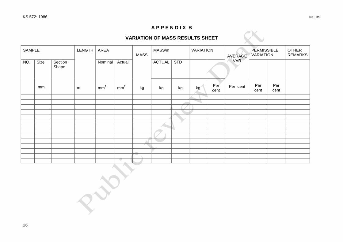
A P P E N D I X B
VARIATION OF MASS RESULTS SHEET
SAMPLE
LENGTH m
AREA
MASS
kg
MASS/m
VARIATION
AVERAGE VAR
Per cent
PERMISSIBLE VARIATION
OTHER REMARKS
NO. Size
mm
Section Shape
Nominal
mm2
Actual
mm
2
ACTUAL
STD
Per cent
Per cent
kg
kg
kg
Per cent