spread foundations
TRANSCRIPT

This article was downloaded by: 10.3.98.104On: 04 Nov 2021Access details: subscription numberPublisher: CRC PressInforma Ltd Registered in England and Wales Registered Number: 1072954 Registered office: 5 Howick Place, London SW1P 1WG, UK
Foundation Systems for High-Rise Structures
Rolf Katzenbach, Steffen Leppla, Deepankar Choudhury
Spread foundations
Publication detailshttps://www.routledgehandbooks.com/doi/10.1201/9781315368870-4
Rolf Katzenbach, Steffen Leppla, Deepankar ChoudhuryPublished online on: 15 Aug 2016
How to cite :- Rolf Katzenbach, Steffen Leppla, Deepankar Choudhury. 15 Aug 2016, Spreadfoundations from: Foundation Systems for High-Rise Structures CRC PressAccessed on: 04 Nov 2021https://www.routledgehandbooks.com/doi/10.1201/9781315368870-4
PLEASE SCROLL DOWN FOR DOCUMENT
Full terms and conditions of use: https://www.routledgehandbooks.com/legal-notices/terms
This Document PDF may be used for research, teaching and private study purposes. Any substantial or systematic reproductions,re-distribution, re-selling, loan or sub-licensing, systematic supply or distribution in any form to anyone is expressly forbidden.
The publisher does not give any warranty express or implied or make any representation that the contents will be complete oraccurate or up to date. The publisher shall not be liable for an loss, actions, claims, proceedings, demand or costs or damageswhatsoever or howsoever caused arising directly or indirectly in connection with or arising out of the use of this material.
Dow
nloa
ded
By:
10.
3.98
.104
At:
21:3
6 04
Nov
202
1; F
or: 9
7813
1536
8870
, cha
pter
3, 1
0.12
01/9
7813
1536
8870
-4
27
Chapter 3
Spread foundations
Spread foundations refer to foundation components that transfer their loads to the subsoil only by normal stresses and shear stresses. Spread foundations are single foundations, strip foundations, or raft foundations. The require-ment for spread foundations is the bearing capacity of the subsoil below the bottom of the foundation. If the subsoil has insufficient bearing capacity, improvement to the subsoil or alternative foundation systems are required.
Basically, the depth of the foundation level is specified to facilitate a frost-free foundation. In Germany, this is at least 80 cm below the surface. Information on the different regional frost penetration depths is contained in [1–3].
The following incidents have to be avoided during the preparation of the foundation level:
• Leaching• Reduction of the bulk density by drifty water• Maceration• Cyclic freezing and unfreezing
Before the installation of the blinding concrete, the foundation level has to be checked by a geotechnical expert.
3.1 SINGLE AND STRIP FOUNDATIONS
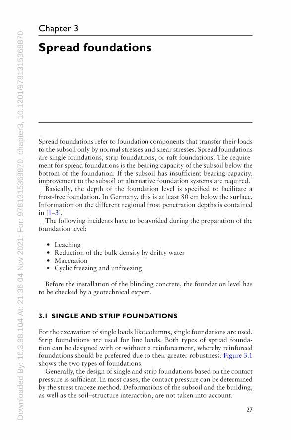
For the excavation of single loads like columns, single foundations are used. Strip foundations are used for line loads. Both types of spread founda-tion can be designed with or without a reinforcement, whereby reinforced foundations should be preferred due to their greater robustness. Figure 3.1 shows the two types of foundations.
Generally, the design of single and strip foundations based on the contact pressure is sufficient. In most cases, the contact pressure can be determined by the stress trapeze method. Deformations of the subsoil and the building, as well as the soil–structure interaction, are not taken into account.
Dow
nloa
ded
By:
10.
3.98
.104
At:
21:3
6 04
Nov
202
1; F
or: 9
7813
1536
8870
, cha
pter
3, 1
0.12
01/9
7813
1536
8870
-4 28 Foundation Systems for High-Rise Structures
3.2 RAFT FOUNDATIONS
Raft foundations are used when the load grid is dense and the deformations of the subsoil and the construction have to be homogenized. Raft founda-tions can be used as a part of a so-called white trough, or in combination with an additional sealing system (e.g., bitumen layers) to prevent ground-water influx [4–7].
The thickness of the reinforcedconcrete slab depends on the bending moment, as well as on the punching (concentrated loads). Increasing the slab thickness or arranging concrete haunches can avoid shear reinforce-ments. To prevent groundwater influx or to repel weather conditions, the crack width of the concrete has to be limited. In any case, the installa-tion of construction joints, expansion joints and settlement joints has to be planned precisely and supervised during the construction phase.
3.3 GEOTECHNICAL ANALYSIS
3.3.1 Basics
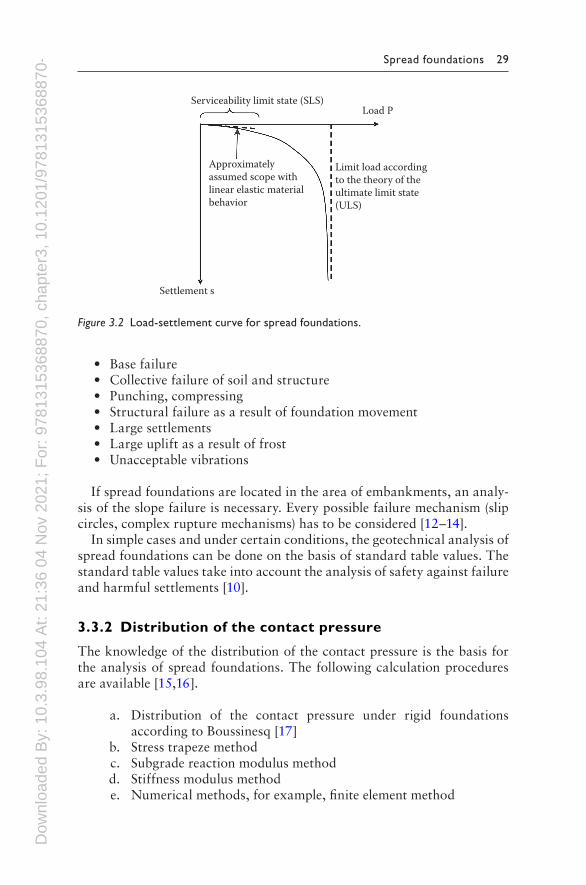
Two different theoretical models are used for the geotechnical analysis of the SLS and the ULS. For the analysis of the stability limit state (SLS), a linear elastic material behavior of the subsoil is considered. In contrast, for the design of the ultimate limit state (ULS), a rigid-plastic material behavior of the subsoil is considered. This issue of spread foundations is explained in Figure 3.2.
According to the technical standards and regulations, the following inci-dents have to be analyzed [8–11]:
• Overall stability• Sliding
Figure 3.1 Single and strip foundation.
Dow
nloa
ded
By:
10.
3.98
.104
At:
21:3
6 04
Nov
202
1; F
or: 9
7813
1536
8870
, cha
pter
3, 1
0.12
01/9
7813
1536
8870
-4 Spread foundations 29
• Base failure• Collective failure of soil and structure• Punching, compressing• Structural failure as a result of foundation movement• Large settlements• Large uplift as a result of frost• Unacceptable vibrations
If spread foundations are located in the area of embankments, an analy-sis of the slope failure is necessary. Every possible failure mechanism (slip circles, complex rupture mechanisms) has to be considered [12–14].
In simple cases and under certain conditions, the geotechnical analysis of spread foundations can be done on the basis of standard table values. The standard table values take into account the analysis of safety against failure and harmful settlements [10].
3.3.2 Distribution of the contact pressure
The knowledge of the distribution of the contact pressure is the basis for the analysis of spread foundations. The following calculation procedures are available [15,16].
a. Distribution of the contact pressure under rigid foundations according to Boussinesq [17]
b. Stress trapeze method c. Subgrade reaction modulus method d. Stiffness modulus method e. Numerical methods, for example, finite element method
Serviceability limit state (SLS)Load P
Settlement s
Approximatelyassumed scope withlinear elastic materialbehavior
Limit load accordingto the theory of theultimate limit state(ULS)
Figure 3.2 Load-settlement curve for spread foundations.
Dow
nloa
ded
By:
10.
3.98
.104
At:
21:3
6 04
Nov
202
1; F
or: 9
7813
1536
8870
, cha
pter
3, 1
0.12
01/9
7813
1536
8870
-4 30 Foundation Systems for High-Rise Structures
The distribution of the contact pressure under rigid foundations according to Boussinesq (a) offers theoretically infinitely large tensions at the edge of the foundation, which cannot arise because of transfer processes in the subsoil under the foundation. This method is applicable only in simple cases.
The simplest procedure is the stress trapeze method (b), because there is only a linear distribution of stresses assumed. The distribution of the contact pressure as a consequence of the stress trapeze method is a useful approach when using small foundations and small foundation depths.
The subgrade reaction modulus method (c) and the stiffness modulus method (d) are suitable, if the foundation depth is big. It can be used for single, strip, and raft foundations. Using the subgrade reaction modu-lus method, the subsoil is considered as a system of independent springs. A uniform load leads to a uniform settlement with no settlement trough. Using the stiffness modulus method, the subsoil is considered as an elastic half-space with a system of connected springs. A uniform load leads to a settlement trough. The stiffness modulus method leads to the most realistic distribution of the contact pressure.
The calculation methods (a) to (d) are approximate solutions to deter-mine the distribution of the contact pressure below a spread foundation. These methods are usually sufficient for the analysis. The most realistic distribution of the contact pressure is given by numerical analysis because the stiffness of the structure as well the nonlinear material behavior of the subsoil can be considered.
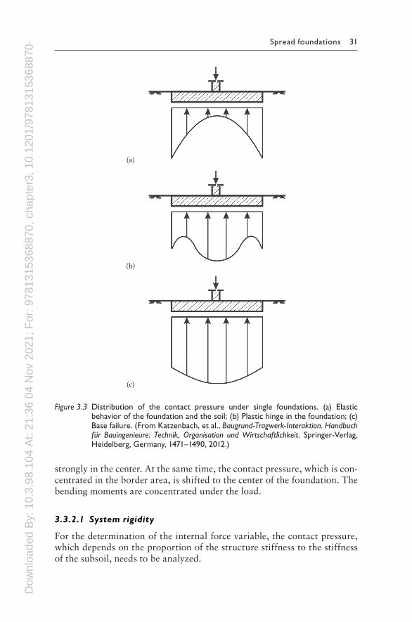
The distribution of the contact pressure depends on the stiffness of the foundation as well as the relation between load and the stability of the sub-soil [18]. The potential distributions of the contact pressure are shown in Figure 3.3. Case (a) shows the distribution of the contact pressure when the bearing capacity is exploited poorly. When the load approaches to the bear-ing capacity two different failure mechanisms may occur. In case (b) the load leads to a plastic hinge inside the foundation which causes a redis-tribution of the contact pressure. In this case the bearing capacity of the foundation depends on the rotation capacity of the plastic hinge. In case (c) the load leads to a redistribution of the contact pressure to the center of the foundation which leads to a base failure.
If the foundation has no sufficient ductility, a brittle failing follows in excess of the internal load-bearing capacity, for example, punching. A redistribution of the contact pressure will not take place.
The assumption of a constant distribution of the contact pressure leads to results on the safe side for analysis of the ULS. For analysis of the SLS, the assumption of a constant distribution of the contact pressure leads to results on the unsafe side.
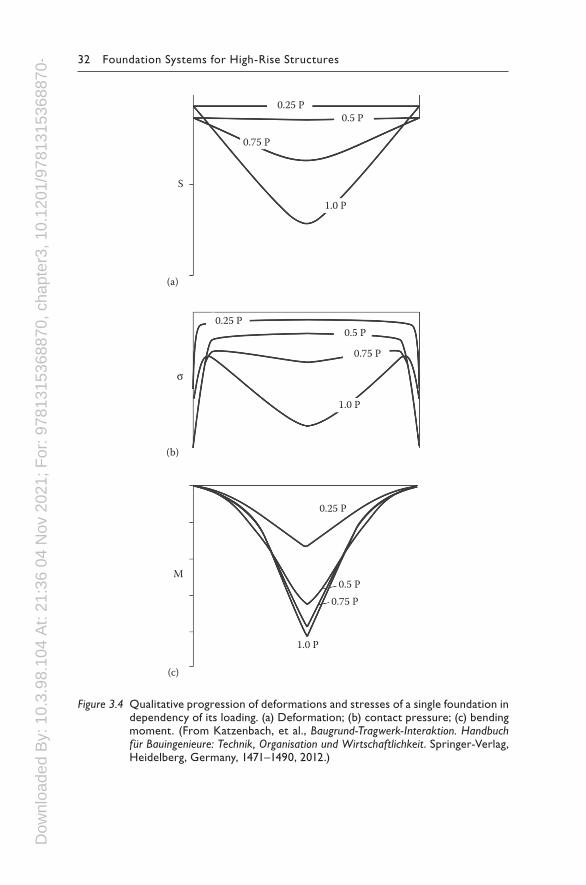
Figure 3.4 shows the settlement trough, the distribution of the contact pressure, and the curve of the moment, depending on the load. With an increasing load, the constant settlements under the foundation increase
Dow
nloa
ded
By:
10.
3.98
.104
At:
21:3
6 04
Nov
202
1; F
or: 9
7813
1536
8870
, cha
pter
3, 1
0.12
01/9
7813
1536
8870
-4 Spread foundations 31
strongly in the center. At the same time, the contact pressure, which is con-centrated in the border area, is shifted to the center of the foundation. The bending moments are concentrated under the load.
3.3.2.1 System rigidity
For the determination of the internal force variable, the contact pressure, which depends on the proportion of the structure stiffness to the stiffness of the subsoil, needs to be analyzed.
(a)
(b)
(c)
Figure 3.3 Distribution of the contact pressure under single foundations. (a) Elastic behavior of the foundation and the soil; (b) Plastic hinge in the foundation; (c) Base failure. (From Katzenbach, et al., Baugrund-Tragwerk-Interaktion. Handbuch für Bauingenieure: Technik, Organisation und Wirtschaftlichkeit. Springer-Verlag, Heidelberg, Germany, 1471–1490, 2012.)
Dow
nloa
ded
By:
10.
3.98
.104
At:
21:3
6 04
Nov
202
1; F
or: 9
7813
1536
8870
, cha
pter
3, 1
0.12
01/9
7813
1536
8870
-4 32 Foundation Systems for High-Rise Structures
0.25 P
0.25 P
0.25 P
0.75 P
0.75 P
0.75 P
0.5 P
0.5 P
0.5 P
1.0 P
1.0 P
1.0 P
S
M
σ
(c)
(a)
(b)
Figure 3.4 Qualitative progression of deformations and stresses of a single foundation in dependency of its loading. (a) Deformation; (b) contact pressure; (c) bending moment. (From Katzenbach, et al., Baugrund-Tragwerk-Interaktion. Handbuch für Bauingenieure: Technik, Organisation und Wirtschaftlichkeit. Springer-Verlag, Heidelberg, Germany, 1471–1490, 2012.)
Dow
nloa
ded
By:
10.
3.98
.104
At:
21:3
6 04
Nov
202
1; F
or: 9
7813
1536
8870
, cha
pter
3, 1
0.12
01/9
7813
1536
8870
-4 Spread foundations 33
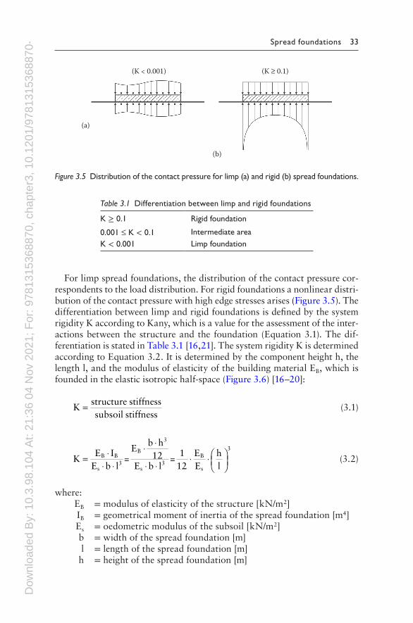
For limp spread foundations, the distribution of the contact pressure cor-respondents to the load distribution. For rigid foundations a nonlinear distri-bution of the contact pressure with high edge stresses arises (Figure 3.5). The differentiation between limp and rigid foundations is defined by the system rigidity K according to Kany, which is a value for the assessment of the inter-actions between the structure and the foundation (Equation 3.1). The dif-ferentiation is stated in Table 3.1 [16,21]. The system rigidity K is determined according to Equation 3.2. It is determined by the component height h, the length l, and the modulus of elasticity of the building material EB, which is founded in the elastic isotropic half-space (Figure 3.6) [16–20]:
Kstructure stiffnesssubsoil stiffness
= (3.1)
KE I
E b l=
Eb h12
E b l=
112
EE
hl
B B
s3
B
3
s3
B
s
3
=⋅
⋅
⋅⋅ ⋅
⋅⋅
⋅
⋅ (3.2)
where: EB = modulus of elasticity of the structure [kN/m2] IB = geometrical moment of inertia of the spread foundation [m4] Es = oedometric modulus of the subsoil [kN/m2] b = width of the spread foundation [m] l = length of the spread foundation [m] h = height of the spread foundation [m]
(K < 0.001) (K ≥ 0.1)
(a)
(b)
Figure 3.5 Distribution of the contact pressure for limp (a) and rigid (b) spread foundations.
Table 3.1 Differentiation between limp and rigid foundations
K ≥ 0.1 Rigid foundation
0.001 ≤ K < 0.1 Intermediate areaK < 0.001 Limp foundation
Dow
nloa
ded
By:
10.
3.98
.104
At:
21:3
6 04
Nov
202
1; F
or: 9
7813
1536
8870
, cha
pter
3, 1
0.12
01/9
7813
1536
8870
-4 34 Foundation Systems for High-Rise Structures
Circular spread foundations with a component height h and a diameter d have a system rigidity K in accordance with
K1
12EE
hd
B
S
3
= ⋅ ⋅
(3.3)
For the calculation of spread foundations, normally only the rigidity of the foundation component is used to consider the rigidity of the building. The rigidity of the rising construction is considered only in special cases.
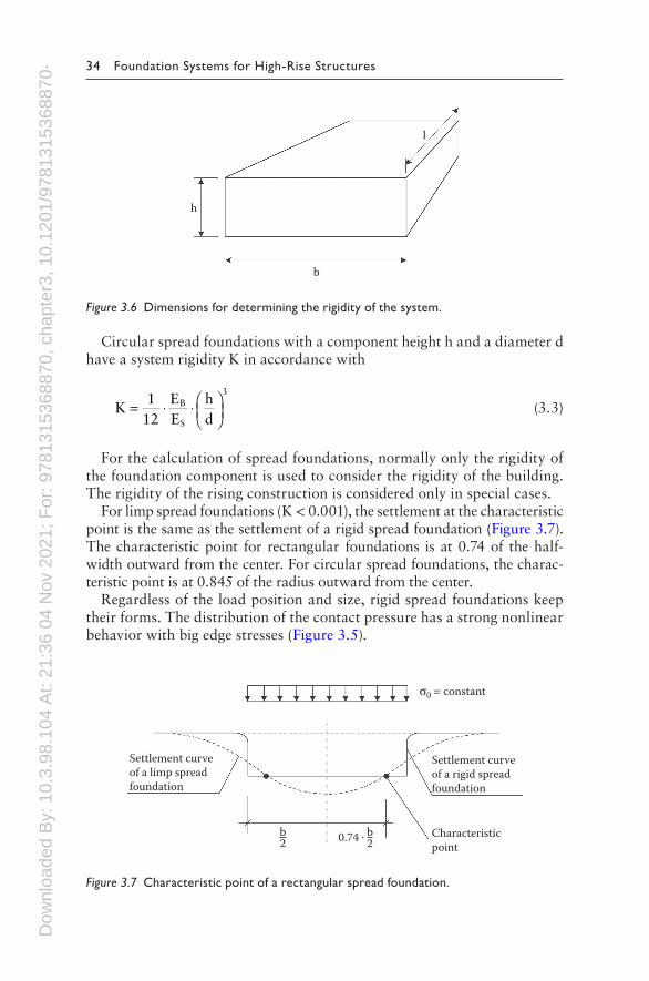
For limp spread foundations (K < 0.001), the settlement at the characteristic point is the same as the settlement of a rigid spread foundation (Figure 3.7). The characteristic point for rectangular foundations is at 0.74 of the half-width outward from the center. For circular spread foundations, the charac-teristic point is at 0.845 of the radius outward from the center.
Regardless of the load position and size, rigid spread foundations keep their forms. The distribution of the contact pressure has a strong nonlinear behavior with big edge stresses (Figure 3.5).
Settlement curveof a limp spreadfoundation
Settlement curveof a rigid spreadfoundation
σ0 = constant
Characteristicpoint
b2 0.74 . b
2
Figure 3.7 Characteristic point of a rectangular spread foundation.
h
b
l
Figure 3.6 Dimensions for determining the rigidity of the system.
Dow
nloa
ded
By:
10.
3.98
.104
At:
21:3
6 04
Nov
202
1; F
or: 9
7813
1536
8870
, cha
pter
3, 1
0.12
01/9
7813
1536
8870
-4 Spread foundations 35
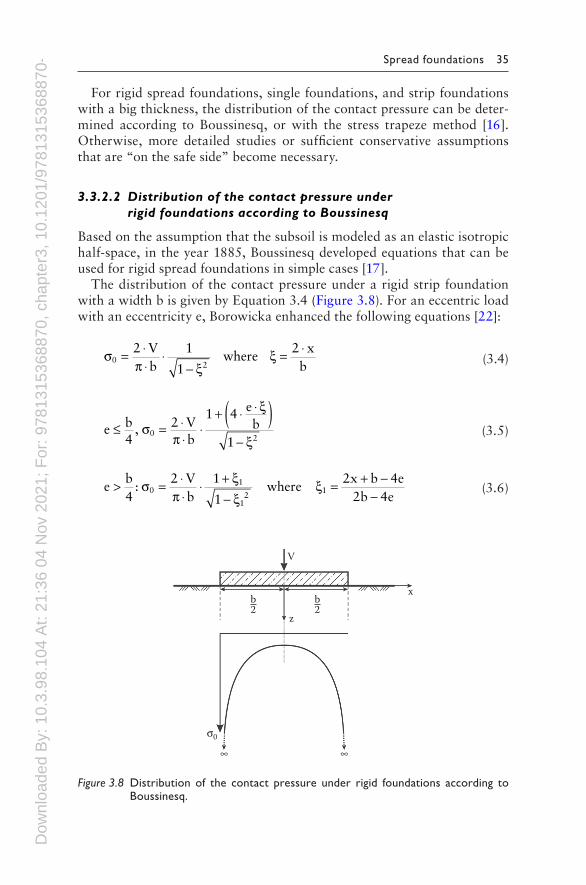
For rigid spread foundations, single foundations, and strip foundations with a big thickness, the distribution of the contact pressure can be deter-mined according to Boussinesq, or with the stress trapeze method [16]. Otherwise, more detailed studies or sufficient conservative assumptions that are “on the safe side” become necessary.
3.3.2.2 Distribution of the contact pressure under rigid foundations according to Boussinesq
Based on the assumption that the subsoil is modeled as an elastic isotropic half-space, in the year 1885, Boussinesq developed equations that can be used for rigid spread foundations in simple cases [17].
The distribution of the contact pressure under a rigid strip foundation with a width b is given by Equation 3.4 (Figure 3.8). For an eccentric load with an eccentricity e, Borowicka enhanced the following equations [22]:
σπ ξ
ξ02
2 Vb
1
1where
2 xb
= ⋅⋅
⋅−
= ⋅ (3.4)
e b4
, 2 Vb
1 4 eb
10
2≤ = ⋅
⋅⋅
+ ⋅ ⋅( )−
σπ
ξ
ξ (3.5)
eb4
:2 V
b1
1where
2x b 4e2b 4e
01
12
1> = ⋅⋅
⋅ +−
= + −−
σπ
ξξ
ξ (3.6)
b2
b2
z
x
V
σ0
∞ ∞
Figure 3.8 Distribution of the contact pressure under rigid foundations according to Boussinesq.
Dow
nloa
ded
By:
10.
3.98
.104
At:
21:3
6 04
Nov
202
1; F
or: 9
7813
1536
8870
, cha
pter
3, 1
0.12
01/9
7813
1536
8870
-4 36 Foundation Systems for High-Rise Structures
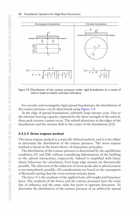
For circular and rectangular rigid spread foundations, the distribution of the contact pressure can be determined using Figure 3.9.
At the edge of spread foundations, infinitely large stresses arise. Due to the ultimate bearing capacity, imposed by the shear strength of the subsoil, these peak stresses cannot occur. The subsoil plasticizes at the edges of the foundations and the stresses shift to the center of the foundations [23].
3.3.2.3 Stress trapeze method
The stress trapeze method is a statically defined method, and it is the oldest to determine the distribution of the contact pressure. The stress trapeze method is based on the beam theory of elastostatic principles.
The distribution of the contact pressure is determined by the equilibrium conditions ΣV and ΣM, without considering deformations of the building or the subsoil interactions, respectively. Subsoil is simplified with linear elastic behaviour for calculation. Even large edge stresses are theoretically possible. The detection of the reduction of stress peaks due to plasticization is not immediately possible. All considerations are based on the assumption of Bernoulli stating that the cross-sections remain plane.
The force V is the resultant of the applied load, self-weight and buoyancy force. The resultant of the forces and the contact pressures have the same line of influence and the same value but point in opposite directions. To determine the distribution of the contact pressure of an arbitrarily spread
Rectangular foundation Circular foundation
a bπ2 ⋅ a ⋅ b ⋅ − ⋅ −
2 2
4 ⋅ V
1 1
σ0 =2 ⋅ y2 ⋅ x
V 1
rR
⋅
−22 ⋅ π ⋅ R2
1
σ0 =
a2
b2b2
a2
V
VV
Vr
R
Ry
x
Figure 3.9 Distribution of the contact pressure under rigid foundations as a result of centric loads on elastic isotropic half-space
Dow
nloa
ded
By:
10.
3.98
.104
At:
21:3
6 04
Nov
202
1; F
or: 9
7813
1536
8870
, cha
pter
3, 1
0.12
01/9
7813
1536
8870
-4 Spread foundations 37
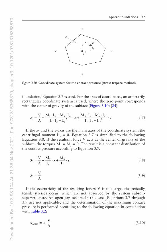
foundation, Equation 3.7 is used. For the axes of coordinates, an arbitrarily rectangular coordinate system is used, where the zero point corresponds with the center of gravity of the subface (Figure 3.10) [24].
σ0y x x xy
x y xy2
x y y xy
x y xy2
VA
M I M II I I
xM I M I
I I Iy= + ⋅ − ⋅
⋅ −⋅ + ⋅ − ⋅
⋅ −⋅ (3.7)
If the x- and the y-axis are the main axes of the coordinate system, the centrifugal moment Ixy = 0. Equation 3.7 is simplified to the following Equation 3.8. If the resultant force V acts at the center of gravity of the subface, the torques Mx = My = 0. The result is a constant distribution of the contact pressure according to Equation 3.9.
σ0y
y
x
x
VA
MI
xMI
y= + ⋅ + ⋅ (3.8)
σ0VA
= (3.9)
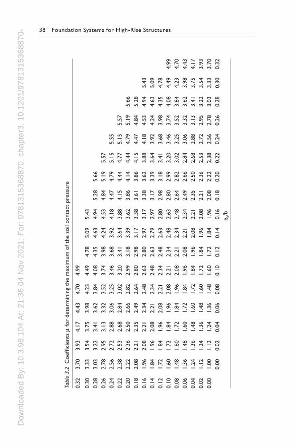
If the eccentricity of the resulting forces V is too large, theoretically tensile stresses occur, which are not absorbed by the system subsoil-superstructure. An open gap occurs. In this case, Equations 3.7 through 3.9 are not applicable, and the determination of the maximum contact pressure is performed according to the following equation in conjunction with Table 3.2:
σ µ0,maxVA
= ⋅ (3.10)
V
xx S
y
y
A
ex
ey
Figure 3.10 Coordinate system for the contact pressure (stress trapeze method).
Dow
nloa
ded
By:
10.
3.98
.104
At:
21:3
6 04
Nov
202
1; F
or: 9
7813
1536
8870
, cha
pter
3, 1
0.12
01/9
7813
1536
8870
-4 38 Foundation Systems for High-Rise Structures
Tabl
e 3.
2 C
oeffi
cien
ts μ
for
dete
rmin
ing
the
max
imum
of t
he s
oil c
onta
ct p
ress
ure
0.32
3.70
3.93
4.17
4.43
4.70
4.99
0.30
3.33
3.54
3.75
3.98
4.23
4.49
4.78
5.09
5.43
0.28
3.03
3.22
3.41
3.62
3.84
4.08
4.35
4.63
4.94
5.28
5.66
0.26
2.78
2.95
3.13
3.32
3.52
3.74
3.98
4.24
4.53
4.84
5.19
5.57
0.24
2.56
2.72
2.88
3.06
3.25
3.46
3.68
3.92
4.18
4.47
4.79
5.15
5.55
0.22
2.38
2.53
2.68
2.84
3.02
3.20
3.41
3.64
3.88
4.15
4.44
4.77
5.15
5.57
0.20
2.22
2.36
2.50
2.66
2.82
2.99
3.18
3.39
3.62
3.86
4.14
4.44
4.79
5.19
5.66
0.18
2.08
2.21
2.35
2.49
2.64
2.80
2.98
3.17
3.38
3.61
3.86
4.15
4.47
4.84
5.28
0.16
1.96
2.08
2.21
2.34
2.48
2.63
2.80
2.97
3.17
3.38
3.62
3.88
4.18
4.53
4.94
5.43
0.14
1.84
1.96
2.08
2.21
2.34
2.48
2.63
2.79
2.97
3.17
3.39
3.64
3.92
4.24
4.63
5.09
0.12
1.72
1.84
1.96
2.08
2.21
2.34
2.48
2.63
2.80
2.98
3.18
3.41
3.68
3.98
4.35
4.78
0.10
1.60
1.72
1.84
1.96
2.08
2.21
2.34
2.48
2.63
2.80
2.99
3.20
3.46
3.74
4.08
4.49
4.99
0.08
1.48
1.60
1.72
1.84
1.96
2.08
2.21
2.34
2.48
2.64
2.82
3.02
3.25
3.52
3.84
4.23
4.70
0.06
1.36
1.48
1.60
1.72
1.84
1.96
2.08
2.21
2.34
2.49
2.66
2.84
3.06
3.32
3.62
3.98
4.43
0.04
1.24
1.36
1.48
1.60
1.72
1.84
1.96
2.08
2.21
2.35
2.50
2.68
2.88
3.13
3.41
3.75
4.17
0.02
1.12
1.24
1.36
1.48
1.60
1.72
1.84
1.96
2.08
2.21
2.36
2.53
2.72
2.95
3.22
3.54
3.93
0.00
1.00
1.12
1.24
1.36
1.48
1.60
1.72
1.84
1.96
2.08
2.22
2.38
2.56
2.78
3.03
3.33
3.70
0.00
0.02
0.04
0.06
0.08
0.10
0.12
0.14
0.16
0.18
0.20
0.22
0.24
0.26
0.28
0.30
0.32
e b/b
Dow
nloa
ded
By:
10.
3.98
.104
At:
21:3
6 04
Nov
202
1; F
or: 9
7813
1536
8870
, cha
pter
3, 1
0.12
01/9
7813
1536
8870
-4 Spread foundations 39
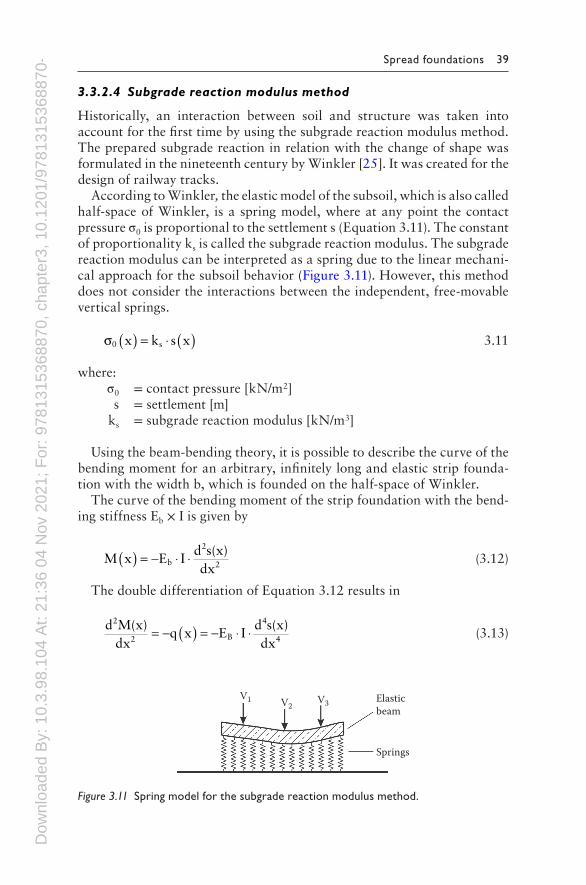
3.3.2.4 Subgrade reaction modulus method
Historically, an interaction between soil and structure was taken into account for the first time by using the subgrade reaction modulus method. The prepared subgrade reaction in relation with the change of shape was formulated in the nineteenth century by Winkler [25]. It was created for the design of railway tracks.
According to Winkler, the elastic model of the subsoil, which is also called half-space of Winkler, is a spring model, where at any point the contact pressure σ0 is proportional to the settlement s (Equation 3.11). The constant of proportionality ks is called the subgrade reaction modulus. The subgrade reaction modulus can be interpreted as a spring due to the linear mechani-cal approach for the subsoil behavior (Figure 3.11). However, this method does not consider the interactions between the independent, free-movable vertical springs.
σ0 sx k s x( ) = ⋅ ( ) 3.11
where: σ0 = contact pressure [kN/m2] s = settlement [m] ks = subgrade reaction modulus [kN/m3]
Using the beam-bending theory, it is possible to describe the curve of the bending moment for an arbitrary, infinitely long and elastic strip founda-tion with the width b, which is founded on the half-space of Winkler.
The curve of the bending moment of the strip foundation with the bend-ing stiffness Eb × I is given by
M x E Id s(x)dx
b
2
2( ) = − ⋅ ⋅ (3.12)
The double differentiation of Equation 3.12 results in
d M(x)
dxq x E I
d s(x)dx
2
2 B
4
4= − ( ) = − ⋅ ⋅ (3.13)
V1 V2V3 Elastic
beam
Springs
Figure 3.11 Spring model for the subgrade reaction modulus method.
Dow
nloa
ded
By:
10.
3.98
.104
At:
21:3
6 04
Nov
202
1; F
or: 9
7813
1536
8870
, cha
pter
3, 1
0.12
01/9
7813
1536
8870
-4 40 Foundation Systems for High-Rise Structures
The action q(x) corresponds to the contact pressure σ0(x), which can be described by
q x x b k s x b E Id s(x)dx
0 s B
4
4( ) = − ( ) ⋅ = − ⋅ ( ) ⋅ = ⋅ ⋅σ (3.14)
With the elastic length L given as
L4 E I
k bB
s
4= ⋅ ⋅⋅
(3.15)
and the elimination of s(x), Equation 3.16 follows. For a large number of boundary conditions, Equation 3.16 can be solved. For an infinite long strip foundation, the distribution of the contact pressure σ0(x), the distribu-tion of the bending moment M(x), and the distribution of the shear forces result according to Equations 3.17 through 3.19.
d M(x)
dx4 M(x)
L0
4
4 4+ = (3.16)
σ0
xLV
2 b Le cos
xL
sinxL
= +⋅ ⋅
⋅ ⋅
− (3.17)
M(x)V L
4e cos
xL
sinxL
xL= ⋅ ⋅ ⋅ −
− (3.18)
Q xV2
e cosxL
xL( ) = ± ⋅ ⋅
− (3.19)
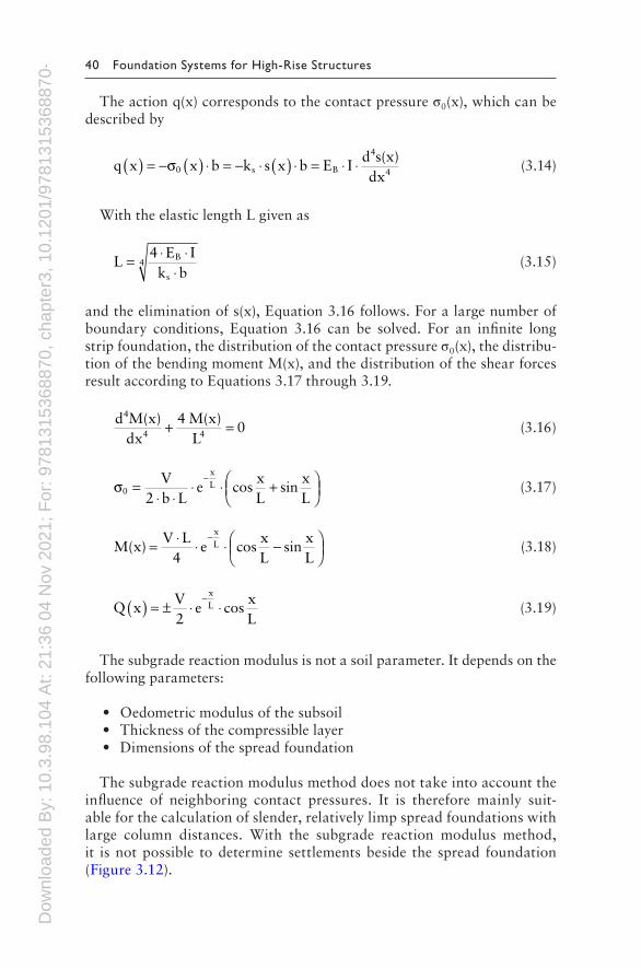
The subgrade reaction modulus is not a soil parameter. It depends on the following parameters:
• Oedometric modulus of the subsoil• Thickness of the compressible layer• Dimensions of the spread foundation
The subgrade reaction modulus method does not take into account the influence of neighboring contact pressures. It is therefore mainly suit-able for the calculation of slender, relatively limp spread foundations with large column distances. With the subgrade reaction modulus method, it is not possible to determine settlements beside the spread foundation (Figure 3.12).
Dow
nloa
ded
By:
10.
3.98
.104
At:
21:3
6 04
Nov
202
1; F
or: 9
7813
1536
8870
, cha
pter
3, 1
0.12
01/9
7813
1536
8870
-4 Spread foundations 41
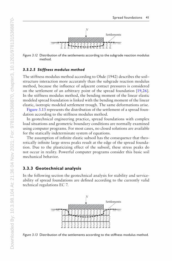
3.3.2.5 Stiffness modulus method
The stiffness modulus method according to Ohde (1942) describes the soil–structure interaction more accurately than the subgrade reaction modulus method, because the influence of adjacent contact pressures is considered on the settlement of an arbitrary point of the spread foundation [19,26]. In the stiffness modulus method, the bending moment of the linear elastic modeled spread foundation is linked with the bending moment of the linear elastic, isotropic modeled settlement trough. The same deformations arise.
Figure 3.13 represents the distribution of the settlement of a spread foun-dation according to the stiffness modulus method.
In geotechnical engineering practice, spread foundations with complex load situations and geometric boundary conditions are normally examined using computer programs. For most cases, no closed solutions are available for the statically indeterminate system of equations.
The assumption of infinite elastic subsoil has the consequence that theo-retically infinite large stress peaks result at the edge of the spread founda-tion. Due to the plasticizing effect of the subsoil, these stress peaks do not occur in reality. Powerful computer programs consider this basic soil mechanical behavior.
3.3.3 Geotechnical analysis
In the following section the geotechnical analysis for stability and service-ability of spread foundations are defined according to the currently valid technical regulations EC 7.
SettlementsV
Figure 3.12 Distribution of the settlements according to the subgrade reaction modulus method.
SettlementsV
Figure 3.13 Distribution of the settlements according to the stiffness modulus method.
Dow
nloa
ded
By:
10.
3.98
.104
At:
21:3
6 04
Nov
202
1; F
or: 9
7813
1536
8870
, cha
pter
3, 1
0.12
01/9
7813
1536
8870
-4 42 Foundation Systems for High-Rise Structures
The analysis of the stability includes
• Analysis of safety against loss of balance because of overturning• Analysis of safety against sliding• Analysis of safety against base failure• Analysis of safety against buoyancy
The analysis of the serviceability includes
• Analysis of the foundation rotation and the limitation of the open gap• Analysis of horizontal displacements• Analysis of settlements and differential settlements
3.3.3.1 Analysis of safety against loss of balance because of overturning
Up to now, the analysis of safety against loss of balance because of over-turning was done by applying the resultant of the forces into the second core width. That means that the lower surface of the spread foundation has only a small part with an open gap. This approach is described in [27,28]. Thus, a resulting force in the first core width creates a compressive stress over the entire lower surface of the spread foundation.
According to the current technical regulations, the analysis of safety against loss of balance because of overturning is based on a principle of the rigid body mechanics. The destabilizing and stabilizing forces are compared based on a fictional tilting edge at the edge of the spread foundation:
E Edst,d stb,d≤ (3.20)
The design value of the destabilizing force is estimated according to Equation 3.21, and the design value of the stabilizing action is estimated according to Equation 3.22:
E E Edst,d G,dst,k G,dst Q,dst,k Q,dst= ⋅ + ⋅γ γ (3.21)
E Estb,d stb,k G,stb= ⋅ γ (3.22)
In reality, the position of the tilting edge depends on the rigidity and the shear strength of the subsoil. With a decreasing rigidity and decreasing shear strength, the tilting edge moves to the center of the lower surface of the spread foundation.
Therefore, this analysis itself is not sufficient. It was complemented by the analysis of the limitation of the open gap, which is defined for the
Dow
nloa
ded
By:
10.
3.98
.104
At:
21:3
6 04
Nov
202
1; F
or: 9
7813
1536
8870
, cha
pter
3, 1
0.12
01/9
7813
1536
8870
-4 Spread foundations 43
serviceability limit state. According to [10], the resultant force of the per-manent loads has to be applied into the first core width and the resultant force of the variable loads has to be applied into the second core width (Figure 3.21).
3.3.3.2 Analysis of safety against sliding
The analysis of safety against sliding (limit state GEO-2) is calculated according to Equation 3.23. The forces parallel to the lower surface of the spread foundation have to be smaller than the total resistance, consisting of slide resistance and passive earth pressure. If the passive earth pressure is considered, the serviceability limit state has to be verified regarding the horizontal displacements.
H R Rd d p,d≤ + (3.23)
where: RR
dk
R,h
=γ
R
Rp,d
p,k
R,h
=γ
The sliding resistance is determined according to the three following cases:
• Sliding in the gap between the spread foundation and in the subjacent, fully consolidated subsoil:
RV tan
dk
R,h
= ⋅ δγ
(3.24)
where: Vk = characteristic value of the vertical loadings [kN] δ = characteristic value of the angle of base friction [°]
• Sliding when the gap passes through the fully consolidated soil, for example, in the arrangement of a foundation cut-off:
RV tan +A c
dk
R,h
=′ ⋅ ′⋅ ϕ
γ (3.25)
where: Vk = characteristic value of the vertical loadings [kN] φ′ = characteristic friction angle for the subsoil under the
spread foundation [°]
Dow
nloa
ded
By:
10.
3.98
.104
At:
21:3
6 04
Nov
202
1; F
or: 9
7813
1536
8870
, cha
pter
3, 1
0.12
01/9
7813
1536
8870
-4 44 Foundation Systems for High-Rise Structures
A = area of the load transmission [m2] c′ = characteristic value of the cohesion of the subsoil [kN/m2]
• Sliding on water-saturated subsoil due to very quick loading:
RA c
du
R,h
= ⋅γ
(3.26)
where: A = Area of the load transmission [m2] cu = Characteristic value of the undrained cohesion of the sub-
soil [kN/m2]
For spread foundations that are concreted in situ, the characteristic value of the angle of base friction δ is the same as the characteristic value of the friction angle φ′ of the soil. For prefabricated spread foundation elements the characteristic value of the angle of base friction δ should be set to 2/3 φ′. The characteristic value of the angle of base friction should be δ ≤ 35°.
A passive earth pressure can be considered if the spread foundation is deep enough. Due to horizontal deformations, the passive earth pressure should be limited to 50% of the possible passive earth pressure. Basically, it must be verified whether the passive earth pressure exists during all pos-sible stages in the construction and the service phase of the foundation.
3.3.3.3 Analysis of safety against base failure
The analysis of safety against base failure is guaranteed if the design value of the bearing capacity Rd is bigger than the design value of the active force Vd. Rd is calculated according to Equation 3.27. The principle scheme of a bearing failure of a spread foundation is shown in Figure 3.14.
RR
dn,k
R,v
=γ
(3.27)
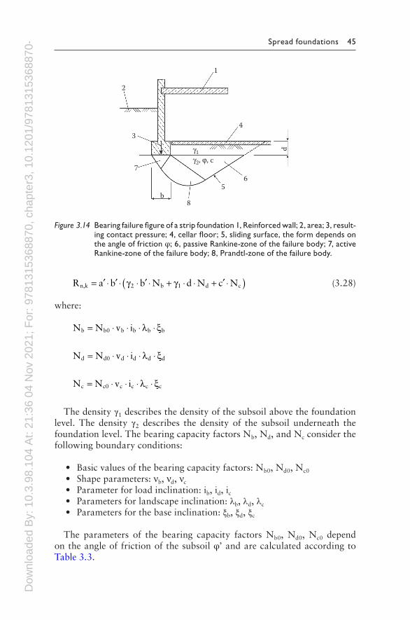
The resistance of the bearing capacity is determined by the soil proper-ties (density, shear parameters), the dimensions and the embedment depth of the spread foundation. Detailed information can be found in the inciden-tal standard [29,30]. The characteristic resistance of the bearing capacity Rn,k is calculated analytically with a trinomial equation, which is based on the moment equilibrium of the failure figure of the bearing capacity in ideal plastic, plane deformation state [31]. The trinomial equation of the bearing capacity considers the width b of the foundation, the embedment depth d of the foundation and the cohesion c′ of the subsoil. All three aspects have to be factorized with the bearing capacity factors Nb, Nd, and Nc:
Dow
nloa
ded
By:
10.
3.98
.104
At:
21:3
6 04
Nov
202
1; F
or: 9
7813
1536
8870
, cha
pter
3, 1
0.12
01/9
7813
1536
8870
-4 Spread foundations 45
R a b b N d N c Nn,k 2 b 1 d c= ′ ⋅ ′ ⋅ ′ ⋅ + ⋅ + ′ ⋅( )⋅ ⋅γ γ (3.28)
where:
N N v ib b0 b b b b= ⋅ ⋅ ⋅ ⋅λ ξ
N N v id d0 d d d d= ⋅ ⋅ ⋅ ⋅λ ξ
N N v ic c0 c c c c= ⋅ ⋅ ⋅ ⋅λ ξ
The density γ1 describes the density of the subsoil above the foundation level. The density γ2 describes the density of the subsoil underneath the foundation level. The bearing capacity factors Nb, Nd, and Nc consider the following boundary conditions:
• Basic values of the bearing capacity factors: Nb0, Nd0, Nc0
• Shape parameters: νb, νd, νc
• Parameter for load inclination: ib, id, ic• Parameters for landscape inclination: λb, λd, λc
• Parameters for the base inclination: ξb, ξd, ξc
The parameters of the bearing capacity factors Nb0, Nd0, Nc0 depend on the angle of friction of the subsoil φ’ and are calculated according to Table 3.3.
8
56
4
1
2
3
7
b
dγ1γ2, ϕ, c
Figure 3.14 Bearing failure figure of a strip foundation 1, Reinforced wall; 2, area; 3, result-ing contact pressure; 4, cellar floor; 5, sliding surface, the form depends on the angle of friction φ; 6, passive Rankine-zone of the failure body; 7, active Rankine-zone of the failure body; 8, Prandtl-zone of the failure body.

Dow
nloa
ded
By:
10.
3.98
.104
At:
21:3
6 04
Nov
202
1; F
or: 9
7813
1536
8870
, cha
pter
3, 1
0.12
01/9
7813
1536
8870
-4 46 Foundation Systems for High-Rise Structures
The shape parameters νb, νd, νc take into account the geometric dimen-sions of the spread foundation. For the standard applicable geometry, the shape parameters are summarized in Table 3.4.
If eccentric forces have to be considered the base area has to be reduced. The resulting load has to be in the center of gravity. The reduced dimensions a′ and b′ are calculated according to Equations 3.29 and 3.30. Basically applied, is a > b and a′ > b′, respectively. For spread foundations with open parts, the external dimensions may be used for the analysis, if the open parts are not bigger than 20% of the whole base area.
′ = −a a 2ea (3.29)
′ = −b b 2eb (3.30)
m m cos m sina2
b2= +⋅ ⋅ω ω (3.31)
where m2
ab
1ab
a =+
′′
+′′
and m2
ba
1ba
b =+
′′
+′′
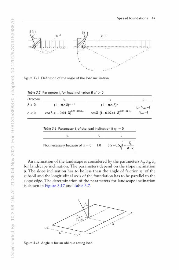
Forces Tk that are parallel to the foundation level are considered by the parameters ib, id, ic for the load inclination. The definition of the angle of the load inclination is shown in Figure 3.15. The determination of the param-eters for the load inclination is shown in Tables 3.5 and 3.6. The orienta-tion of the acting forces is determined by the angle ω (Figure 3.16). For a strip foundation ω = 90°.
Table 3.3 Basic values of the bearing capacity factors
Foundation width Nb0 Foundation depth Nd0 Cohesion Nc0
(Nd0–1) tan φ tan tan2 452
� +
⋅ ⋅ϕ π ϕeNd0 −1tanϕ
Table 3.4 Shape parameters νi
Floor plan νb νd νc (φ ≠ 0) νc (φ = 0)
Strip 1.0 1.0 1.0 1.0
Rectangle 1 0 3− . ⋅′′
ba
1+′′
⋅ba
sinϕvd d0
d0
NN⋅ −
−1
11 0 2+ ⋅
′′
.ba
Square/Circle 0.7 1 + sinφvd d0
d0
NN⋅ −
−1
11.2
Dow
nloa
ded
By:
10.
3.98
.104
At:
21:3
6 04
Nov
202
1; F
or: 9
7813
1536
8870
, cha
pter
3, 1
0.12
01/9
7813
1536
8870
-4 Spread foundations 47
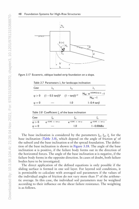
An inclination of the landscape is considered by the parameters λb, λd, λc for landscape inclination. The parameters depend on the slope inclination β. The slope inclination has to be less than the angle of friction φ′ of the subsoil and the longitudinal axis of the foundation has to be parallel to the slope edge. The determination of the parameters for landscape inclination is shown in Figure 3.17 and Table 3.7.
γ1 .d γ1 .dS Sδ (+) δ (–)
Figure 3.15 Definition of the angle of the load inclination.
δ
ω
b'
Tka'
Figure 3.16 Angle ω for an oblique acting load.
Table 3.6 Parameter ii of the load inclination if φ′ = 0
ib id ic
Not necessary, because of φ = 0 1.0 0 5 0 5 1. .+′ ⋅
− TA c
k
Table 3.5 Parameter ii for load inclination if φ′ > 0
Direction ib id icδ > 0 (1 – tan δ)m + 1 (1 – tan δ)m
i NN
d d0
d0
⋅ −−
11δ < 0 cos .
. .δ δ ϕ⋅ ⋅( ) + ⋅1 0 04
0 64 0 028− cos .. .δ δ ϕ⋅ ⋅( ) +
1 0 02440 03 0 04−
Dow
nloa
ded
By:
10.
3.98
.104
At:
21:3
6 04
Nov
202
1; F
or: 9
7813
1536
8870
, cha
pter
3, 1
0.12
01/9
7813
1536
8870
-4 48 Foundation Systems for High-Rise Structures
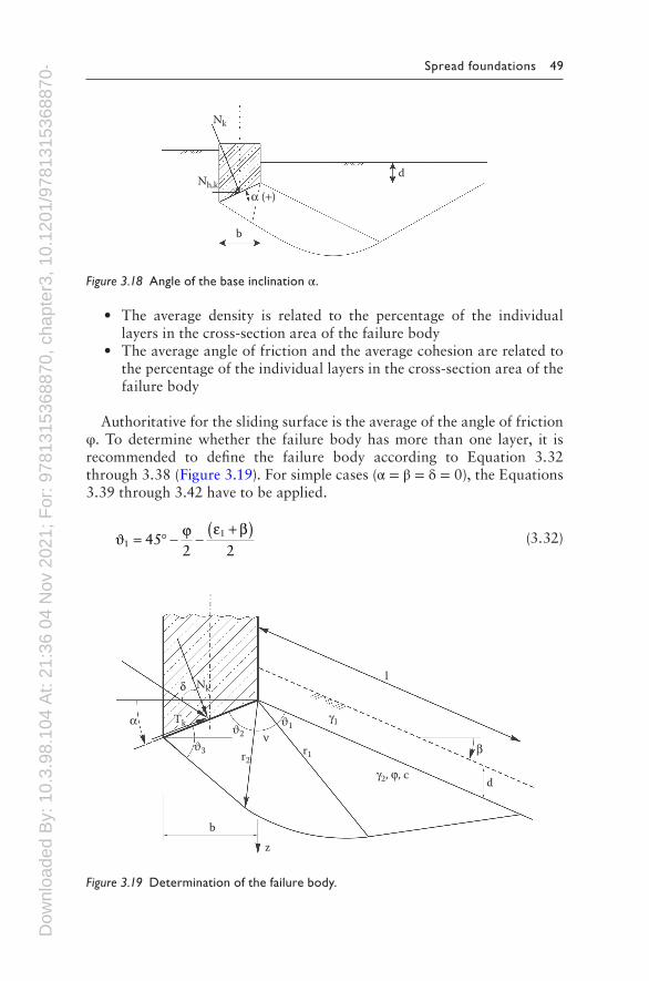
The base inclination is considered by the parameters ξb, ξd, ξc for the base inclination (Table 3.8), which depend on the angle of friction φ’ of the subsoil and the base inclination α of the spread foundation. The defini-tion of the base inclination is shown in Figure 3.18. The angle of the base inclination α is positive, if the failure body forms out in the direction of the horizontal forces. The angle of the base inclination α is negative, if the failure body forms in the opposite direction. In cases of doubt, both failure bodies have to be investigated.
The direct application of the defined equations is only possible if the sliding surface is formed in one soil layer. For layered soil conditions, it is permissible to calculate with averaged soil parameters if the values of the individual angles of friction do not vary more than 5° of the arithme-tic average. In this case, the individual soil parameters may be weighted according to their influence on the shear failure resistance. The weighting is as follows.
βNk
b'b
dTk
eb
δ (+)
Figure 3.17 Eccentric, oblique loaded strip foundation on a slope.
Table 3.7 Parameters λi for landscape inclination
Case λb λd λc
φ > 0 (1 – 0.5 tanβ)6 (1 – tanβ)1,9N e
Nd0
tan
d0
⋅ ⋅ ⋅− −−
0 0349 11
. β ϕ
φ = 0 — 1.0 1–0.4 tanβ
Table 3.8 Coefficient ξi of the base inclination
Case ξb ξd ξc
φ > 0 e−0.045 · α · tan φ e−0.045 · α · tan φ e−0.045 · α · tan φ
φ = 0 — 1.0 1−0.0068α
Dow
nloa
ded
By:
10.
3.98
.104
At:
21:3
6 04
Nov
202
1; F
or: 9
7813
1536
8870
, cha
pter
3, 1
0.12
01/9
7813
1536
8870
-4 Spread foundations 49
• The average density is related to the percentage of the individual layers in the cross-section area of the failure body
• The average angle of friction and the average cohesion are related to the percentage of the individual layers in the cross-section area of the failure body
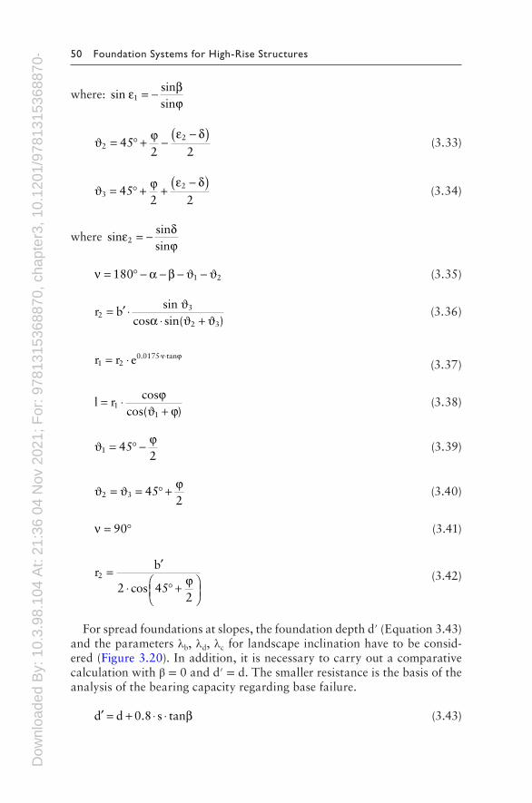
Authoritative for the sliding surface is the average of the angle of friction φ. To determine whether the failure body has more than one layer, it is recommended to define the failure body according to Equation 3.32 through 3.38 (Figure 3.19). For simple cases (α = β = δ = 0), the Equations 3.39 through 3.42 have to be applied.
ϑ ϕ ε β1
1452 2
= ° − −+( ) (3.32)
d
z
b
lNk
r1r2
Tk
δ
β
α γ1ϑ1ϑ2ϑ3
ν
γ2, ϕ, c
Figure 3.19 Determination of the failure body.
Nk
Nh,k
b
d
α (+)
Figure 3.18 Angle of the base inclination α.
Dow
nloa
ded
By:
10.
3.98
.104
At:
21:3
6 04
Nov
202
1; F
or: 9
7813
1536
8870
, cha
pter
3, 1
0.12
01/9
7813
1536
8870
-4 50 Foundation Systems for High-Rise Structures
where: sinsinsin
1ε βϕ
= −
ϑ2 452 2
= ° + −−( )ϕ ε δ2 (3.33)
ϑ3 452 2
= ° + +−( )ϕ ε δ2 (3.34)
where sinsinsin
2ε δϕ
= −
ν α β= ° − − − −180 1 2ϑ ϑ (3.35)
r bsin
cos sin( )2
3
2 3
= ′ ⋅⋅ +
ϑϑ ϑα
(3.36)
r r e1 20.0175 tan= ⋅ ⋅ ⋅ν ϕ
(3.37)
l rcos
cos( )1
1
=+
⋅ ϕϕϑ
(3.38)
ϑ1 452
= ° − ϕ (3.39)
ϑ ϑ2 3 452
= = ° + ϕ (3.40)
ν = °90 (3.41)
rb
2 cos 452
2 =′
⋅ ° +
ϕ (3.42)
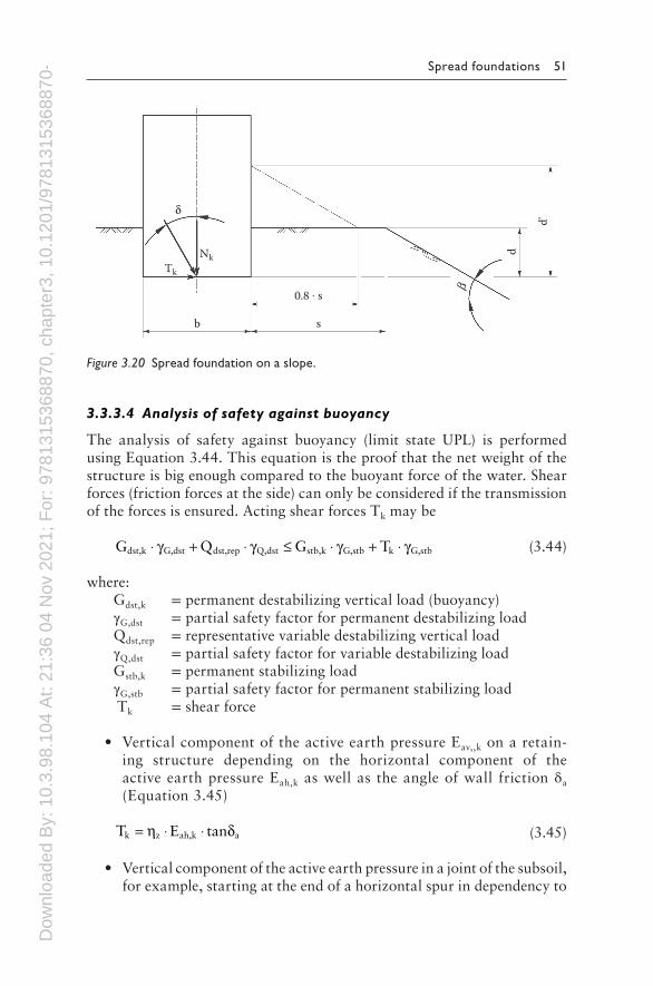
For spread foundations at slopes, the foundation depth d′ (Equation 3.43) and the parameters λb, λd, λc for landscape inclination have to be consid-ered (Figure 3.20). In addition, it is necessary to carry out a comparative calculation with β = 0 and d′ = d. The smaller resistance is the basis of the analysis of the bearing capacity regarding base failure.
′ = + ⋅ ⋅d d 0.8 s tanβ (3.43)
Dow
nloa
ded
By:
10.
3.98
.104
At:
21:3
6 04
Nov
202
1; F
or: 9
7813
1536
8870
, cha
pter
3, 1
0.12
01/9
7813
1536
8870
-4 Spread foundations 51
3.3.3.4 Analysis of safety against buoyancy
The analysis of safety against buoyancy (limit state UPL) is performed using Equation 3.44. This equation is the proof that the net weight of the structure is big enough compared to the buoyant force of the water. Shear forces (friction forces at the side) can only be considered if the transmission of the forces is ensured. Acting shear forces Tk may be
G Q G Tdst,k G,dst dst,rep Q,dst stb,k G,stb k G,stb⋅ + ⋅ ≤ ⋅ + ⋅γ γ γ γ (3.44)
where: Gdst,k = permanent destabilizing vertical load (buoyancy)γG,dst = partial safety factor for permanent destabilizing load Qdst,rep = representative variable destabilizing vertical loadγQ,dst = partial safety factor for variable destabilizing load Gstb,k = permanent stabilizing loadγG,stb = partial safety factor for permanent stabilizing load Tk = shear force
• Vertical component of the active earth pressure Eav,,k on a retain-ing structure depending on the horizontal component of the active earth pressure Eah,k as well as the angle of wall friction δa (Equation 3.45)
T E tank z ah,k a= ⋅ ⋅η δ (3.45)
• Vertical component of the active earth pressure in a joint of the subsoil, for example, starting at the end of a horizontal spur in dependency to
d
d'
sb
NkTk
0.8 . s
δ
β
Figure 3.20 Spread foundation on a slope.
Dow
nloa
ded
By:
10.
3.98
.104
At:
21:3
6 04
Nov
202
1; F
or: 9
7813
1536
8870
, cha
pter
3, 1
0.12
01/9
7813
1536
8870
-4 52 Foundation Systems for High-Rise Structures
the horizontal component of the active earth pressure and the angle of friction φʹ of the subsoil:
T E tank z ah,k= ⋅ ⋅ ′η ϕ (3.46)
The smallest possible horizontal earth pressure min Eah,k has to be used. For the design situation BS-P and BS-T, the adjustment factor is ηz = 0.80. For the design situation BS-A, the adjustment factor is ηz = 0.90. Only in justified cases can cohesion be taken into account, but it has to be reduced by the adjustment factors. For permanent structures, it has to be deter-mined that in design situation BS-A, the safety against buoyancy is given without any shear forces Tk.
3.3.3.5 Analysis of foundation rotation and limitation of the open gap
Generally, the serviceability limit states refer to absolute deformations and displacements as well as differential deformations. In special cases, for example, time-dependent material behavior displacement rates have to be considered.
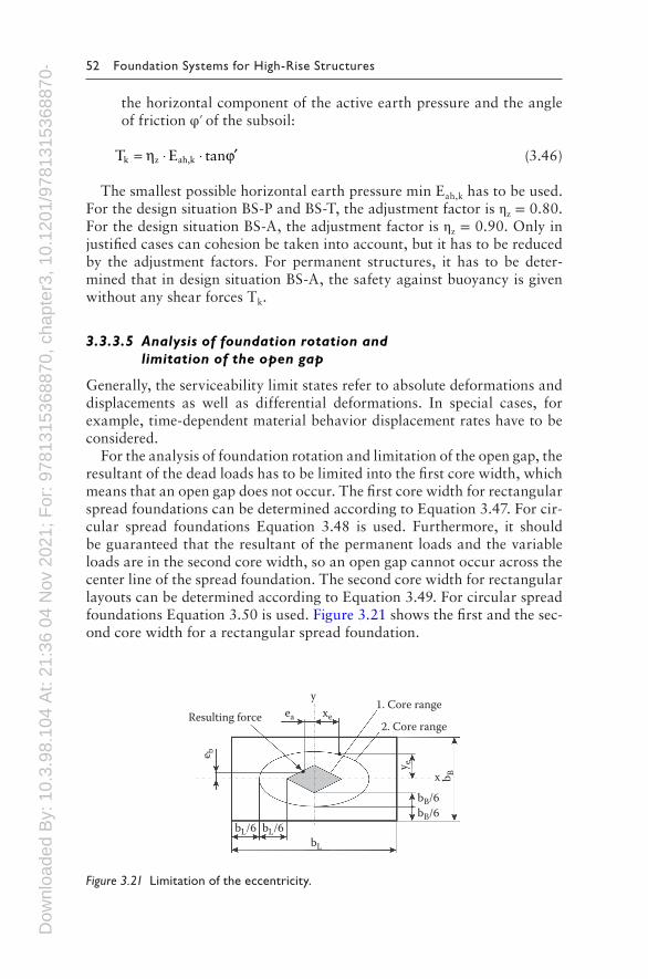
For the analysis of foundation rotation and limitation of the open gap, the resultant of the dead loads has to be limited into the first core width, which means that an open gap does not occur. The first core width for rectangular spread foundations can be determined according to Equation 3.47. For cir-cular spread foundations Equation 3.48 is used. Furthermore, it should be guaranteed that the resultant of the permanent loads and the variable loads are in the second core width, so an open gap cannot occur across the center line of the spread foundation. The second core width for rectangular layouts can be determined according to Equation 3.49. For circular spread foundations Equation 3.50 is used. Figure 3.21 shows the first and the sec-ond core width for a rectangular spread foundation.
1. Core rangeResulting force
2. Core range
x
xeea
e b
b B
y e
bL
y
bL/6
bB/6bB/6
bL/6
Figure 3.21 Limitation of the eccentricity.
Dow
nloa
ded
By:
10.
3.98
.104
At:
21:3
6 04
Nov
202
1; F
or: 9
7813
1536
8870
, cha
pter
3, 1
0.12
01/9
7813
1536
8870
-4 Spread foundations 53
xa
yb
16
e e+ = (3.47)
e 0.25 r≤ ⋅ (3.48)
xa
yb
=19
e2
e2
+
(3.49)
e 0.59 r≤ ⋅ (3.50)
For single and strip foundations, which are founded on medium-dense, non-cohesive soils and stiff cohesive soils, respectively, no incompatible distortions of the foundation can be expected if the acceptable eccentricity is observed.
The analysis of foundation rotation and limitation of the open gap is mandatory according to [10], if the analysis of safety against loss of balance because of overturning is carried out by using one edge of the spread foun-dation as a tilting edge.
3.3.3.6 Analysis of horizontal displacements
Generally, for spread foundations the analysis of horizontal displacement is observed, if:
• The analysis of safety against sliding is performed without consider-ing a passive earth pressure.
• For medium-dense, non-cohesive soils and stiff cohesive soils, respec-tively, only two-thirds of the characteristic sliding resistance in the foundation level and not more than one-third of the characteristic earth pressure are considered.
If these arguments are not true, it is necessary to analyze the possible horizontal displacements. Permanent loads and variable loads, as well as infrequent or unique loads, have to be considered.
3.3.3.7 Analysis of settlements and differential settlements
The determinations for settlements of spread foundations are conducted in accordance with [32]. Normally, the influence depth of the contact pressure is between z = b and z = 2b.
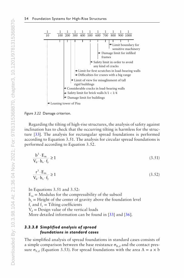
Due to the complex interaction between the subsoil and the construc-tion, it is difficult to provide information about the acceptable settlements or differential settlements for constructions [33]. Figure 3.22 indicates the damage factors for the angular distortion as a result of settlements [33–35].
Dow
nloa
ded
By:
10.
3.98
.104
At:
21:3
6 04
Nov
202
1; F
or: 9
7813
1536
8870
, cha
pter
3, 1
0.12
01/9
7813
1536
8870
-4 54 Foundation Systems for High-Rise Structures
Regarding the tilting of high-rise structures, the analysis of safety against inclination has to check that the occurring tilting is harmless for the struc-ture [33]. The analysis for rectangular spread foundations is performed according to Equation 3.51. The analysis for circular spread foundations is performed according to Equation 3.52.
b E
V h f1
3m
d s y
⋅⋅ ⋅
≥ (3.51)
r E
V h f1
3m
d s y
⋅⋅ ⋅
≥ (3.52)
In Equations 3.51 and 3.52:Em = Modulus for the compressibility of the subsoilhs = Height of the center of gravity above the foundation levelfr and fy = Tilting coefficientsVd = Design value of the vertical loadsMore detailed information can be found in [33] and [36].
3.3.3.8 Simplified analysis of spread foundations in standard cases
The simplified analysis of spread foundations in standard cases consists of a simple comparison between the base resistance σR,d and the contact pres-sure σE,d (Equation 3.53). For spread foundations with the area A = a × b
Limit boundary forsensitive machinery
110
Damage limit for infilledframes
Safety limit in order to avoidany kind of cracks
Limit for first scratches in load-bearing wallsDifficulties for cranes with a big range
Limit of view for misaglinment of tallrigid buildings
Considerable cracks in load-bearing wallsSafety limit for brick walls h/1 < 1/4Damage limit for buildings
Leaning tower of Pisa
1100
1200
1300
1400
1500
1600
1700
1800
1900
11000
Figure 3.22 Damage criterion.
Dow
nloa
ded
By:
10.
3.98
.104
At:
21:3
6 04
Nov
202
1; F
or: 9
7813
1536
8870
, cha
pter
3, 1
0.12
01/9
7813
1536
8870
-4 Spread foundations 55
or Aʹ = aʹ × bʹ, the analysis of safety against sliding and base failure, as well as the analysis of the serviceability limit state, can be applied in standard cases. These standard cases include:
• Horizontal lower surface of the foundation and an almost horizontal landscape and soil layers
• Sufficient strength of the subsoil into a depth of twice the width of the foundation below the foundation level (minimum 2 m)
• No regular dynamic or mainly dynamic loads; no pore water pressure in cohesive soils
• Passive earth pressure can only be applied if it is assured by construc-tive or other procedures
• The inclination of the resultant of the contact pressure observes the rule tanδ = Hk/Vk ≤ 0.2 (δ = inclination of the resultant of the con-tact pressure; Hk = characteristic horizontal forces; Vk = characteris-tic vertical forces)
• The admissible eccentricity of the resultant of the contact pressure is observed
• The analysis of safety against loss of balance because of overturning is observed
σ σE,d R,d≤ (3.53)
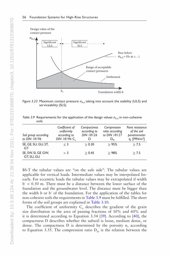
The design values of the contact pressure σR,d are based on the combined examination of the base failure and the settlements. If only the SLS is ana-lyzed, the admissible contact pressure increases with an increasing width of the spread foundation. If only the ULS is analyzed, the admissible con-tact pressure decreases with an increasing width of the spread foundation. Figure 3.23 shows the two fundamental demands for an adequate analysis against base failure (ULS) and the analysis of the settlements (SLS). For foundation widths that are bigger than the width bs, the acceptable contact pressure decreases because of settlements.
The design values of the contact pressure σR,d for simplified analysis of strip foundations are specified in tables. The tabular values can also be used for single foundations [10,37,38].
If the foundation level is more than 2 m below the surface on all sides, the tabular values can be raised. The raise can be 1.4 times the unloading due to the excavation below a depth of ≥2 m under the surface.
The settlement values in the tables refer to detached strip foundations with a central loading (no eccentricity). If eccentric loads occur, the service-ability has to be analyzed. For the application of the current table values, it is essential to notice that in earlier editions of these tables, characteristic values were given [10].
The simplified analysis of the ULS and SLS of strip foundations in non-cohesive soils considers the design situation BS-P. For the design situation
Dow
nloa
ded
By:
10.
3.98
.104
At:
21:3
6 04
Nov
202
1; F
or: 9
7813
1536
8870
, cha
pter
3, 1
0.12
01/9
7813
1536
8870
-4 56 Foundation Systems for High-Rise Structures
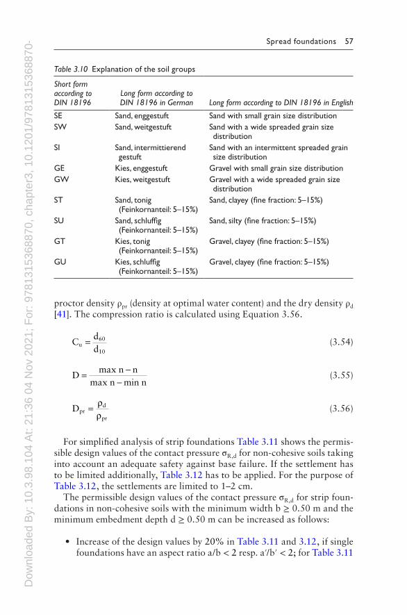
BS-T the tabular values are “on the safe side”. The tabular values are applicable for vertical loads. Intermediate values may be interpolated lin-early. For eccentric loads the tabular values may be extrapolated if width b′ < 0.50 m. There must be a distance between the lower surface of the foundation and the groundwater level. The distance must be bigger than the width b or b′ of the foundation. For the application of the tables for non-cohesive soils the requirements in Table 3.9 must be fulfilled. The short forms of the soil groups are explained in Table 3.10.
The coefficient of uniformity Cu describes the gradient of the grain size distribution in the area of passing fractions of 10% and 60% and it is determined according to Equation 3.54 [39]. According to [40], the compactness D describes whether the subsoil is loose, medium dense, or dense. The compactness D is determined by the porosity n, according to Equation 3.55. The compression ratio Dpr is the relation between the
Table 3.9 Requirements for the application of the design values σR,d in non-cohesive soils
Soil group according to DIN 18196
Coefficient of uniformity
according to DIN 18196 Cu
Compactness according to DIN 18126
D
Compression ratio according to DIN 18127
DPr
Point resistance of the soil
penetrometer qc [MN/m2]
SE, GE, SU, GU, ST, GT
≤ 3 ≥ 0.30 ≥ 95% ≥ 7.5
SE, SW, SI, GE GW, GT, SU, GU
> 3 ≥ 0.45 ≥ 98% ≥ 7.5
Design value of thecontact pressure
SignificantULS
SignificantSLS
Base failureσR,d = f(b, ϕ, c, ...)
Range of acceptablecontact pressures
Settlement
Foundation width bbs
σR,d
Figure 3.23 Maximum contact pressure σR,d taking into account the stability (ULS) and serviceability (SLS).
Dow
nloa
ded
By:
10.
3.98
.104
At:
21:3
6 04
Nov
202
1; F
or: 9
7813
1536
8870
, cha
pter
3, 1
0.12
01/9
7813
1536
8870
-4 Spread foundations 57
proctor density ρpr (density at optimal water content) and the dry density ρd [41]. The compression ratio is calculated using Equation 3.56.
Cdd
u60
10
= (3.54)
Dmax n n
max n min n= −
− (3.55)
Dprd
pr
= ρρ
(3.56)
For simplified analysis of strip foundations Table 3.11 shows the permis-sible design values of the contact pressure σR,d for non-cohesive soils taking into account an adequate safety against base failure. If the settlement has to be limited additionally, Table 3.12 has to be applied. For the purpose of Table 3.12, the settlements are limited to 1–2 cm.
The permissible design values of the contact pressure σR,d for strip foun-dations in non-cohesive soils with the minimum width b ≥ 0.50 m and the minimum embedment depth d ≥ 0.50 m can be increased as follows:
• Increase of the design values by 20% in Table 3.11 and 3.12, if single foundations have an aspect ratio a/b < 2 resp. a′/b′ < 2; for Table 3.11
Table 3.10 Explanation of the soil groups
Short form according to DIN 18196
Long form according to DIN 18196 in German Long form according to DIN 18196 in English
SE Sand, enggestuft Sand with small grain size distributionSW Sand, weitgestuft Sand with a wide spreaded grain size
distributionSI Sand, intermittierend
gestuftSand with an intermittent spreaded grain size distribution
GE Kies, enggestuft Gravel with small grain size distributionGW Kies, weitgestuft Gravel with a wide spreaded grain size
distributionST Sand, tonig
(Feinkornanteil: 5–15%)Sand, clayey (fine fraction: 5–15%)
SU Sand, schluffig (Feinkornanteil: 5–15%)
Sand, silty (fine fraction: 5–15%)
GT Kies, tonig (Feinkornanteil: 5–15%)
Gravel, clayey (fine fraction: 5–15%)
GU Kies, schluffig (Feinkornanteil: 5–15%)
Gravel, clayey (fine fraction: 5–15%)

Dow
nloa
ded
By:
10.
3.98
.104
At:
21:3
6 04
Nov
202
1; F
or: 9
7813
1536
8870
, cha
pter
3, 1
0.12
01/9
7813
1536
8870
-4 58 Foundation Systems for High-Rise Structures
it is only applied if the embedment depth d is bigger than 0.60 × b resp. 0.60 × b′
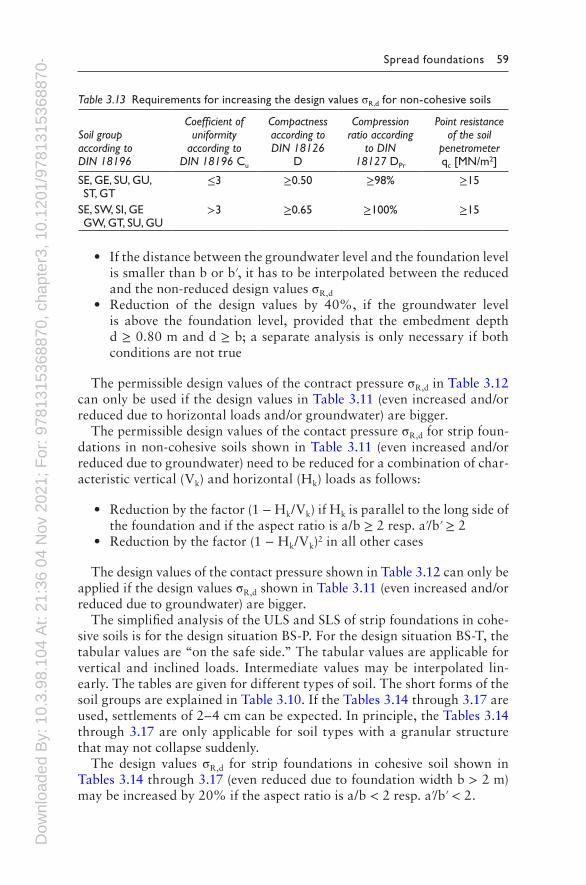
• Increase of the design values by 50% in Tables 3.11 and 3.12, if the subsoil complies the values in Table 3.13 into a depth of twice the width under the foundation level (minimum 2 m under foundation level)
The permissible design values of the contact pressure for strip founda-tions in non-cohesive soils in Table 3.11 (even increased and/or reduced due to horizontal loads) have to be reduced if groundwater has to be considered:
• Reduction of the design values by 40%, if the groundwater level is the same as the foundation level
Table 3.12 Design values σR,d for strip foundations in non-cohesive soils and limitation of the settlements to 1–2 cm with a vertical resultant of the contact pressure
Smallest embedment depth of the foundation [m]
Design value of the contact pressure σR,d[kN/m2] in dependence of the foundation width b resp. bʹ
0.50 m 1.00 m 1.50 m 2.00 m 2.50 m 3.00 m0.50 280 420 460 390 350 3101.00 380 520 500 430 380 3401.50 480 620 550 480 410 3602.00 560 700 590 500 430 390For buildings with an embedment depth 0.30 m ≤ d ≤ 0.50 m and foundation width b resp. b′ ≥ 0.30 m
210
Table 3.11 Design values σR,d for strip foundations in non-cohesive soils and sufficient safety against hydraulic failure with a vertical resultant of the contact pressure
Smallest embedment depth of the foundation [m]
Design value of the contact pressure σR,d [kN/m2] in dependence of the foundation width b resp. bʹ
0.50 m 1.00 m 1.50 m 2.00 m 2.50 m 3.00 m
0.50 280 420 560 700 700 7001.00 380 520 660 800 800 8001.50 480 620 760 900 900 9002.00 560 700 840 980 980 980
For buildings with an embedment depth 0.30 m ≤ d ≤ 0.50 m and foundation width b resp. b′ ≥ 0.30 m
210
Dow
nloa
ded
By:
10.
3.98
.104
At:
21:3
6 04
Nov
202
1; F
or: 9
7813
1536
8870
, cha
pter
3, 1
0.12
01/9
7813
1536
8870
-4 Spread foundations 59
• If the distance between the groundwater level and the foundation level is smaller than b or b′, it has to be interpolated between the reduced and the non-reduced design values σR,d
• Reduction of the design values by 40%, if the groundwater level is above the foundation level, provided that the embedment depth d ≥ 0.80 m and d ≥ b; a separate analysis is only necessary if both conditions are not true
The permissible design values of the contract pressure σR,d in Table 3.12 can only be used if the design values in Table 3.11 (even increased and/or reduced due to horizontal loads and/or groundwater) are bigger.
The permissible design values of the contact pressure σR,d for strip foun-dations in non-cohesive soils shown in Table 3.11 (even increased and/or reduced due to groundwater) need to be reduced for a combination of char-acteristic vertical (Vk) and horizontal (Hk) loads as follows:
• Reduction by the factor (1 − Hk/Vk) if Hk is parallel to the long side of the foundation and if the aspect ratio is a/b ≥ 2 resp. aʹ/bʹ ≥ 2
• Reduction by the factor (1 − Hk/Vk)2 in all other cases
The design values of the contact pressure shown in Table 3.12 can only be applied if the design values σR,d shown in Table 3.11 (even increased and/or reduced due to groundwater) are bigger.
The simplified analysis of the ULS and SLS of strip foundations in cohe-sive soils is for the design situation BS-P. For the design situation BS-T, the tabular values are “on the safe side.” The tabular values are applicable for vertical and inclined loads. Intermediate values may be interpolated lin-early. The tables are given for different types of soil. The short forms of the soil groups are explained in Table 3.10. If the Tables 3.14 through 3.17 are used, settlements of 2–4 cm can be expected. In principle, the Tables 3.14 through 3.17 are only applicable for soil types with a granular structure that may not collapse suddenly.
The design values σR,d for strip foundations in cohesive soil shown in Tables 3.14 through 3.17 (even reduced due to foundation width b > 2 m) may be increased by 20% if the aspect ratio is a/b < 2 resp. aʹ/bʹ < 2.
Table 3.13 Requirements for increasing the design values σR,d for non-cohesive soils
Soil group according to DIN 18196
Coefficient of uniformity
according to DIN 18196 Cu
Compactness according to DIN 18126
D
Compression ratio according
to DIN 18127 DPr
Point resistance of the soil
penetrometer qc [MN/m2]
SE, GE, SU, GU, ST, GT
≤3 ≥0.50 ≥98% ≥15
SE, SW, SI, GE GW, GT, SU, GU
>3 ≥0.65 ≥100% ≥15

Dow
nloa
ded
By:
10.
3.98
.104
At:
21:3
6 04
Nov
202
1; F
or: 9
7813
1536
8870
, cha
pter
3, 1
0.12
01/9
7813
1536
8870
-4 60 Foundation Systems for High-Rise Structures
Table 3.15 Design values σR,d for strip foundations in mixed soils
Mixed soils (SU*, ST, ST*, GU*, GT* according to DIN 18196)
Smallest embedment depth of the foundation [m]
Design values σR,d of the contact pressure [kN/m2]
Consistency
Stiff Semi-solid Solid
0.50 210 310 4601.00 250 390 5301.50 310 460 6202.00 350 520 700Unconfined compressive strength qu,k [kN/m2]
120–300 300–700 >700
Table 3.16 Design values σR,d for strip foundations in clay, silty soils
Clay, silty soils (UM, TL, TM according to DIN 18196)
Smallest embedment depth of the foundation [m]
Design values σR,d of the contact pressure [kN/m2]
Consistency
Stiff Semi-solid Solid
0.50 170 240 3901.00 200 290 4501.50 220 350 5002.00 250 390 560Unconfined compressive strength qu,k [kN/m2]
120–300 300–700 >700
Table 3.14 Design values σR,d for strip foundations in silt
Silt (UL according to DIN 18126) consistency: Solid to semisolid
Smallest embedment depth of the foundation [m]
Design value σR,d of the contact pressure [kN/m2]
0.50 1801.00 2501.50 3102.00 350Unconfined compressive strength qu,k [kN/m2]
120
Dow
nloa
ded
By:
10.
3.98
.104
At:
21:3
6 04
Nov
202
1; F
or: 9
7813
1536
8870
, cha
pter
3, 1
0.12
01/9
7813
1536
8870
-4 Spread foundations 61
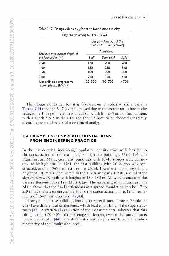
The design values σR,d for strip foundations in cohesive soil shown in Tables 3.14 through 3.17 (even increased due to the aspect ratio) have to be reduced by 10% per meter at foundation width b = 2–5 m. For foundations with a width b > 5 m the ULS and the SLS have to be checked separately according to the classic soil mechanical analysis.
3.4 EXAMPLES OF SPREAD FOUNDATIONS FROM ENGINEERING PRACTICE
In the last decades, increasing population density worldwide has led to the construction of more and higher high-rise buildings. Until 1960, in Frankfurt am Main, Germany, buildings with 10–15 storeys were consid-ered to be high-rise. In 1961, the first building with 20 storeys was con-structed, and in 1969 the first Commerzbank Tower with 30 storeys and a height of 130 m was completed. In the 1970s and early 1980s, several other skyscrapers were built with heights of 150–180 m. All were founded in the very settlement-active Frankfurt Clay. The experiences in Frankfurt am Main show, that the final settlements of a spread foundation can be 1.7 to 2.0 times the settlements at the end of the construction phase. Final settle-ments of 15–35 cm occurred [42,43].
Nearly all high-rise buildings founded on spread foundations in Frankfurt Clay have differential settlements, which lead to a tilting of the superstruc-tures [43]. A statistical evaluation of the measurements indicates that this tilting is up to 20–30% of the average settlement, even if the foundation is loaded centrically [44]. The differential settlements result from the inho-mogeneity of the Frankfurt subsoil.
Table 3.17 Design values σR,d for strip foundations in clay
Clay (TA according to DIN 18196)
Smallest embedment depth of the foundation [m]
Design values σR,d of the contact pressure [kN/m2]
Consistency
Stiff Semi-solid Solid
0.50 130 200 2801.00 150 250 3401.50 180 290 3802.00 210 320 420Unconfined compressive strength qu,k [kN/m2]
120–300 300–700 >700

Dow
nloa
ded
By:
10.
3.98
.104
At:
21:3
6 04
Nov
202
1; F
or: 9
7813
1536
8870
, cha
pter
3, 1
0.12
01/9
7813
1536
8870
-4 62 Foundation Systems for High-Rise Structures
3.4.1 High-rise building complex of Zürich Assurance
The high-rise building complex of the Zürich Assurance Company in Frankfurt am Main, Germany, was constructed from 1959 to 1963. It con-sists of two towers 63 m and 70 m high, respectively, and an annex building up to eight storeys. The whole complex has two sublevels and is founded on a spread foundation. The foundation depth is 7 m below the surface. The ground view is shown in Figure 3.24.
The soil and groundwater conditions are representative for Frankfurt am Main. At the surface are fillings and quaternary sands and gravel. At a depth of about 7 m below the surface, begins the tertiary Frankfurt Clay, which consists of alternating layers of stiff to semisolid clay and limestone. At a depth of 67 m below the surface follows the Frankfurt Limestone. The groundwater level is about 5–6 m below the surface.
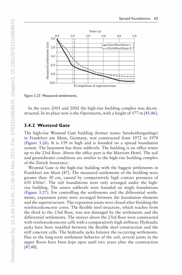
The measured settlements at the end of the construction of the super-structure are about 60% of the final settlements (Figure 3.25). After the end of the construction, the settlement rate decreased due to the consolida-tion process. About 5 years after the end of the construction, the settle-ments come to an end at about 8.5–9.5 cm.
Complex of theZürichassurance II
Complex of theZürichassurance II
Annex building andunderground parking
0 10 20 50 m
Metro tunnel
N
Figure 3.24 Ground view of the high-rise building complex of Zürich Assurance.
Dow
nloa
ded
By:
10.
3.98
.104
At:
21:3
6 04
Nov
202
1; F
or: 9
7813
1536
8870
, cha
pter
3, 1
0.12
01/9
7813
1536
8870
-4 Spread foundations 63
In the years 2001 and 2002 the high-rise building complex was decon-structed. In its place now is the Opernturm, with a height of 177 m [45,46].
3.4.2 Westend Gate
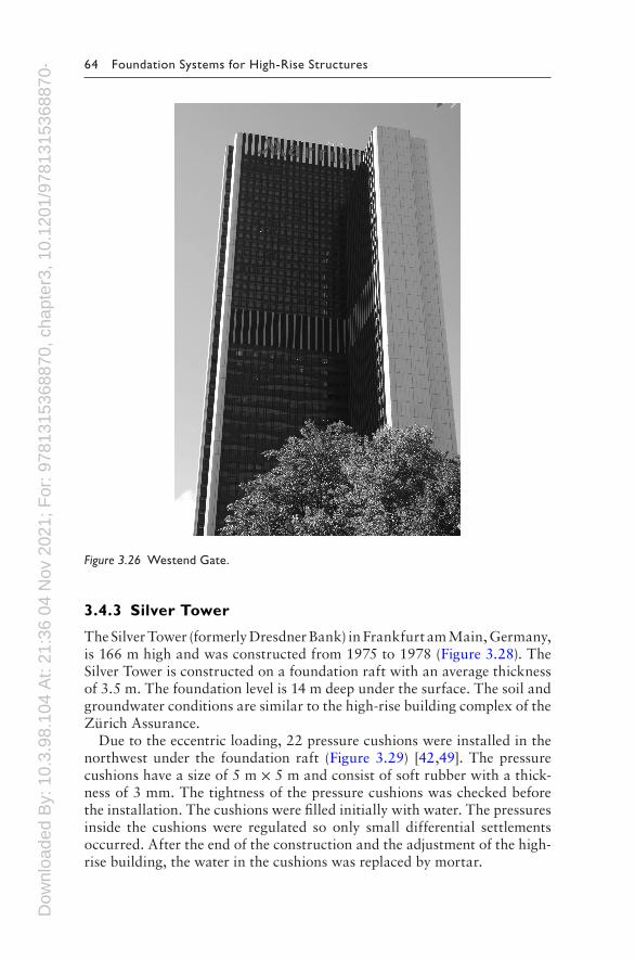
The high-rise Westend Gate building (former name: Senckenberganlage) in Frankfurt am Main, Germany, was constructed from 1972 to 1974 (Figure 3.26). It is 159 m high and is founded on a spread foundation system. The basement has three sublevels. The building is an office tower up to the 23rd floor. Above the office part is the Marriott Hotel. The soil and groundwater conditions are similar to the high-rise building complex of the Zürich Assurance.
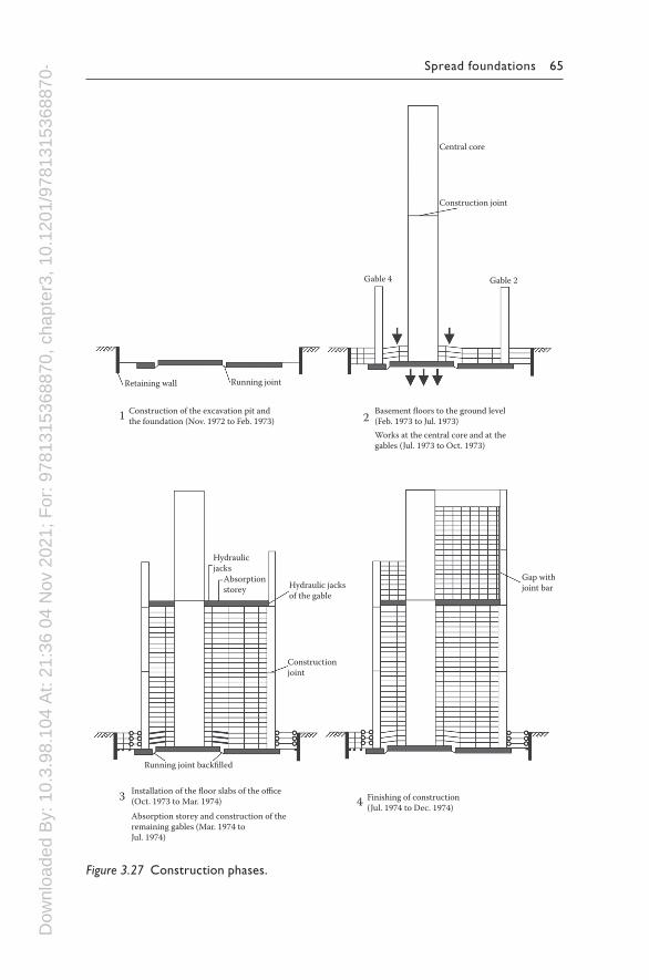
Westend Gate is the high-rise building with the biggest settlements in Frankfurt am Main [47]. The measured settlements of the building were greater than 30 cm, caused by comparatively high contact pressures of 650 kN/m2. The raft foundations were only arranged under the high-rise building. The annex sublevels were founded on single foundations (Figure 3.27). For controlling the settlements and the differential settle-ments, expansion joints were arranged between the foundation elements and the superstructure. The expansion joints were closed after finishing the reinforcedconcrete cores. The flexible steel structure, which reaches from the third to the 23rd floor, was not damaged by the settlements and the differential settlements. The storeys above the 23rd floor were constructed with reinforcedconcrete cells with a comparatively high stiffness. Hydraulic jacks have been installed between the flexible steel construction and the stiff concrete cells. The hydraulic jacks balance the occurring settlements. Due to the long-term settlement behavior of the soil, several joints in the upper floors have been kept open until two years after the construction [47,48].
0.00.0
2.0
4.0
6.0
8.0
10.0Completion of superstructure
Mea
sure
d se
ttle
men
ts (c
m)
Years (a)1.0 2.0 3.0 4.0 5.0
Zürichhochhaus IZürichhochhaus II
Figure 3.25 Measured settlements.
Dow
nloa
ded
By:
10.
3.98
.104
At:
21:3
6 04
Nov
202
1; F
or: 9
7813
1536
8870
, cha
pter
3, 1
0.12
01/9
7813
1536
8870
-4 64 Foundation Systems for High-Rise Structures
3.4.3 Silver Tower
The Silver Tower (formerly Dresdner Bank) in Frankfurt am Main, Germany, is 166 m high and was constructed from 1975 to 1978 (Figure 3.28). The Silver Tower is constructed on a foundation raft with an average thickness of 3.5 m. The foundation level is 14 m deep under the surface. The soil and groundwater conditions are similar to the high-rise building complex of the Zürich Assurance.
Due to the eccentric loading, 22 pressure cushions were installed in the northwest under the foundation raft (Figure 3.29) [42,49]. The pressure cushions have a size of 5 m × 5 m and consist of soft rubber with a thick-ness of 3 mm. The tightness of the pressure cushions was checked before the installation. The cushions were filled initially with water. The pressures inside the cushions were regulated so only small differential settlements occurred. After the end of the construction and the adjustment of the high-rise building, the water in the cushions was replaced by mortar.
Figure 3.26 Westend Gate.
Dow
nloa
ded
By:
10.
3.98
.104
At:
21:3
6 04
Nov
202
1; F
or: 9
7813
1536
8870
, cha
pter
3, 1
0.12
01/9
7813
1536
8870
-4 Spread foundations 65
Central core
Construction joint
Gable 4
Retaining wall Running joint
Hydraulicjacks
Hydraulic jacksof the gable
Gap withjoint bar
Constructionjoint
Running joint backfilled
Installation of the floor slabs of the office(Oct. 1973 to Mar. 1974) Finishing of construction
(Jul. 1974 to Dec. 1974)Absorption storey and construction of theremaining gables (Mar. 1974 toJul. 1974)
Absorptionstorey
Construction of the excavation pit andthe foundation (Nov. 1972 to Feb. 1973)1 2
3 4
Basement floors to the ground level(Feb. 1973 to Jul. 1973)Works at the central core and at thegables (Jul. 1973 to Oct. 1973)
Gable 2
Figure 3.27 Construction phases.
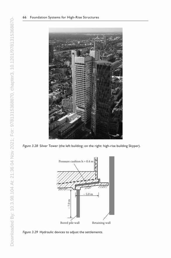
Dow
nloa
ded
By:
10.
3.98
.104
At:
21:3
6 04
Nov
202
1; F
or: 9
7813
1536
8870
, cha
pter
3, 1
0.12
01/9
7813
1536
8870
-4 66 Foundation Systems for High-Rise Structures
Pressure cushion h = 0.4 m
Retaining wallBored pile wall
∼ 5.0 m
∼ 7.
0 m
Figure 3.29 Hydraulic devices to adjust the settlements.
Figure 3.28 Silver Tower (the left building; on the right: high-rise building Skyper).
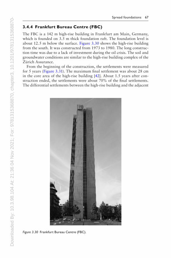
Dow
nloa
ded
By:
10.
3.98
.104
At:
21:3
6 04
Nov
202
1; F
or: 9
7813
1536
8870
, cha
pter
3, 1
0.12
01/9
7813
1536
8870
-4 Spread foundations 67
3.4.4 Frankfurt Bureau Centre (FBC)
The FBC is a 142 m high-rise building in Frankfurt am Main, Germany, which is founded on 3.5 m thick foundation raft. The foundation level is about 12.5 m below the surface. Figure 3.30 shows the high-rise building from the south. It was constructed from 1973 to 1980. The long construc-tion time was due to a lack of investment during the oil crisis. The soil and groundwater conditions are similar to the high-rise building complex of the Zürich Assurance.
From the beginning of the construction, the settlements were measured for 5 years (Figure 3.31). The maximum final settlement was about 28 cm in the core area of the high-rise building [42]. About 1.5 years after con-struction ended, the settlements were about 70% of the final settlements. The differential settlements between the high-rise building and the adjacent
Figure 3.30 Frankfurt Bureau Centre (FBC).
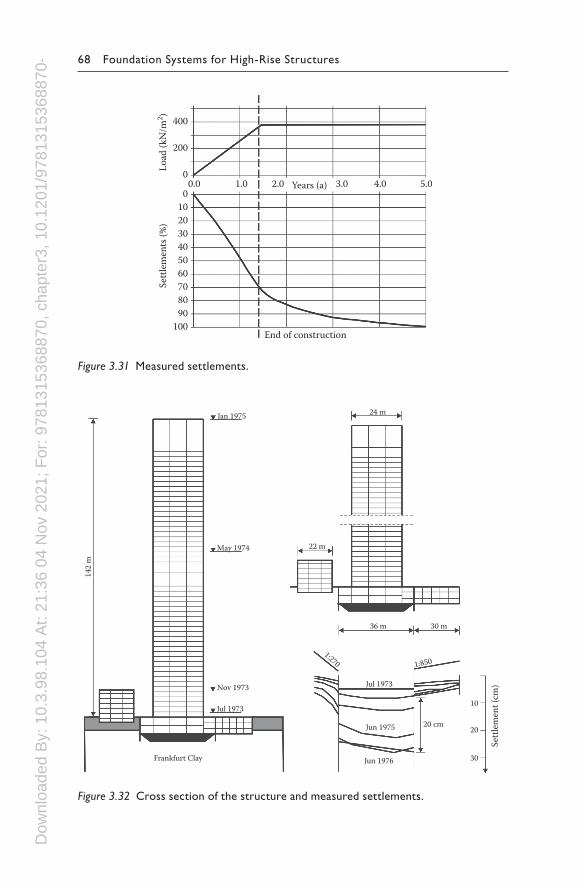
Dow
nloa
ded
By:
10.
3.98
.104
At:
21:3
6 04
Nov
202
1; F
or: 9
7813
1536
8870
, cha
pter
3, 1
0.12
01/9
7813
1536
8870
-4 68 Foundation Systems for High-Rise Structures
Jan 1975
May 1974
Nov 1973
Jul 1973
Jul 1973
1:270 1:850
Jun 1976
Jun 1975
10
Sett
lem
ent (
cm)
20
30
20 cm
30 m36 m
142
m
22 m
24 m
Frankfurt Clay
Figure 3.32 Cross section of the structure and measured settlements.
Years (a)
400
200
0
00.0 1.0 2.0 3.0 4.0 5.0
102030405060708090
100End of construction
Settl
emen
ts (%
)Lo
ad (k
N/m
2 )
Figure 3.31 Measured settlements.
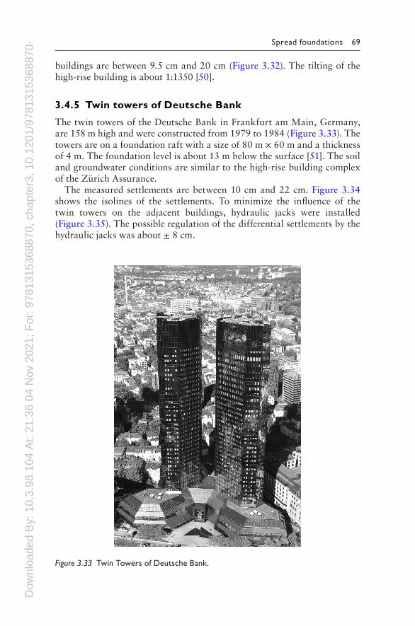
Dow
nloa
ded
By:
10.
3.98
.104
At:
21:3
6 04
Nov
202
1; F
or: 9
7813
1536
8870
, cha
pter
3, 1
0.12
01/9
7813
1536
8870
-4 Spread foundations 69
buildings are between 9.5 cm and 20 cm (Figure 3.32). The tilting of the high-rise building is about 1:1350 [50].
3.4.5 Twin towers of Deutsche Bank
The twin towers of the Deutsche Bank in Frankfurt am Main, Germany, are 158 m high and were constructed from 1979 to 1984 (Figure 3.33). The towers are on a foundation raft with a size of 80 m × 60 m and a thickness of 4 m. The foundation level is about 13 m below the surface [51]. The soil and groundwater conditions are similar to the high-rise building complex of the Zürich Assurance.
The measured settlements are between 10 cm and 22 cm. Figure 3.34 shows the isolines of the settlements. To minimize the influence of the twin towers on the adjacent buildings, hydraulic jacks were installed (Figure 3.35). The possible regulation of the differential settlements by the hydraulic jacks was about ± 8 cm.
Figure 3.33 Twin Towers of Deutsche Bank.
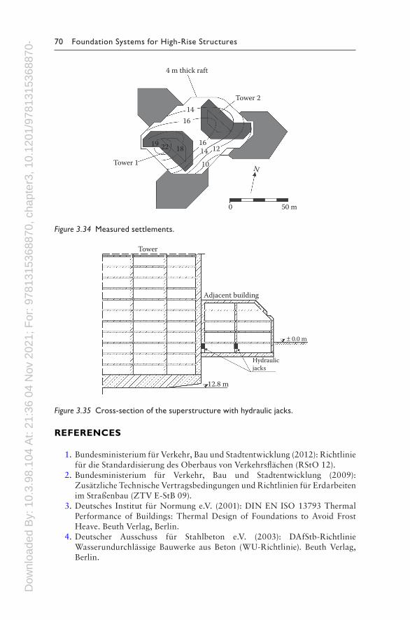
Dow
nloa
ded
By:
10.
3.98
.104
At:
21:3
6 04
Nov
202
1; F
or: 9
7813
1536
8870
, cha
pter
3, 1
0.12
01/9
7813
1536
8870
-4 70 Foundation Systems for High-Rise Structures
REFERENCES
1. Bundesministerium für Verkehr, Bau und Stadtentwicklung (2012): Richtlinie für die Standardisierung des Oberbaus von Verkehrsflächen (RStO 12).
2. Bundesministerium für Verkehr, Bau und Stadtentwicklung (2009): Zusätzliche Technische Vertragsbedingungen und Richtlinien für Erdarbeiten im Straßenbau (ZTV E-StB 09).
3. Deutsches Institut für Normung e.V. (2001): DIN EN ISO 13793 Thermal Performance of Buildings: Thermal Design of Foundations to Avoid Frost Heave. Beuth Verlag, Berlin.
4. Deutscher Ausschuss für Stahlbeton e.V. (2003): DAfStb-Richtlinie Wasserundurchlässige Bauwerke aus Beton (WU-Richtlinie). Beuth Verlag, Berlin.
4 m thick raft
Tower 214
16
1614 12
10
0 50 m
N
182219
Tower 1
Figure 3.34 Measured settlements.
Tower
Adjacent building
12.8 m
Hydraulicjacks
± 0.0 m
Figure 3.35 Cross-section of the superstructure with hydraulic jacks.
Dow
nloa
ded
By:
10.
3.98
.104
At:
21:3
6 04
Nov
202
1; F
or: 9
7813
1536
8870
, cha
pter
3, 1
0.12
01/9
7813
1536
8870
-4 Spread foundations 71
5. Deutscher Ausschuss für Stahlbeton e.V. (2006): Heft 555 Erläuterungen zur DAfStb-Richtlinie Wasserundurchlässige Bauwerke aus Beton. Beuth Verlag, Berlin.
6. Lohmeyer, G.; Ebeling, K. (2013): Weiße Wannen einfach und sicher. 10. Auflage, Verlag Bau + Technik, Düsseldorf, Germany.
7. Haack, A.; Emig, K.-F. (2003): Abdichtungen im Gründungsbereich und auf genutzten Deckenflächen. 2. Auflage, Ernst & Sohn Verlag, Berlin.
8. Deutsches Institut für Normung e.V. (2014): DIN EN 1997-1 Eurocode 7: Geotechnical design: Part 1: General rules. Beuth Verlag, Berlin.
9. Deutsches Institut für Normung e.V. (2010): DIN EN 1997-1/NA National Annex: Nationally Determined Parameters—Eurocode 7: Geotechnical Design–Part 1: General Rules. Beuth Verlag, Berlin.
10. Deutsches Institut für Normung e.V. (2010): DIN 1054 Subsoil: Verification of the Safety of Earthworks and Foundations—Supplementary Rules to DIN EN 1997-1. Beuth Verlag, Berlin.
11. Deutsches Institut für Normung e.V. (2012): DIN 1054 Subsoil: Verification of the Safety of Earthworks and Foundations—Supplementary rules to DIN EN 1997-1:2010; Amendment A1:2012. Beuth Verlag, Berlin.
12. Deutsches Institut für Normung e.V. (2009): DIN 4084 Soil: Calculation of Embankment Failure and Overall Stability of Retaining Structures. Beuth Verlag, Berlin.
13. Deutsches Institut für Normung e.V. (2012): DIN 4084 Ground: Calculation of the Overall Stability—Supplement 1: Examples of calculation. Beuth Verlag, Berlin.
14. Hettler, A. (2000): Gründung von Hochbauten. Ernst & Sohn Verlag, Berlin.
15. Deutsches Institut für Normung e.V. (1974): DIN 4018 Subsoil: Contact Pressure Distribution Under Raft Foundations, Analysis. Beuth Verlag, Berlin.
16. Deutsches Institut für Normung e.V. (1981): DIN 4018 Supplement 1 Subsoil: Analysis of Contact Pressure Distribution Under Raft Foundations; Explanations and Examples of Analysis. Beuth Verlag, Berlin.
17. Boussinesq, M.J. (1885): Application des Potentials à l’Étude de l’Équilibre et du Mouvement des Solides Élastiques. Gauthier-Villard, Paris, France.
18. Katzenbach, R.; Zilch, K.; Moormann, C. (2012): Baugrund-Tragwerk-Interaktion. Handbuch für Bauingenieure: Technik, Organisation und Wirtschaftlichkeit. Springer Verlag, Heidelberg, Germany, 1471–1490.
19. Kany, M. (1959): Berechnung von Flächengründungen. Ernst & Sohn Verlag, Berlin.
20. Kany, M. (1974): Berechnung von Flächengründungen, Band 2, 2. Auflage, Ernst & Sohn Verlag, Berlin.
21. Meyerhof, G.G. (1979): General report: Soil–structure interaction and foun-dations. 6th Panamerican Conference on Soil Mechanics and Foundation Engineering, 2–7 December, Lima, Peru, 109–140.
22. Borowicka, H. (1943): Über ausmittig belastete starre Platten auf elastisch-isotropem Untergrund. Ingenieur-Archiv, XIV. Band, Heft 1, Springer Verlag, Berlin, 1–8.
23. Lang, H.J.; Huder, J.; Amann, P. (2003): Bodenmechanik und Grundbau. 7. Auflage, Springer Verlag, Berlin.
Dow
nloa
ded
By:
10.
3.98
.104
At:
21:3
6 04
Nov
202
1; F
or: 9
7813
1536
8870
, cha
pter
3, 1
0.12
01/9
7813
1536
8870
-4 72 Foundation Systems for High-Rise Structures
24. Smoltczyk, U.; Vogt, N. (2009): Flachgründungen. Grundbautaschenbuch, Teil 3: Gründungen und geotechnische Bauwerke. 7. Auflage, Ernst & Sohn Verlag, Berlin, 1–71.
25. Winkler, E. (1867): Die Lehre von der Elastizität und Festigkeit. Verlag Dominicus, Prague, Czech Republic.
26. Ohde, J. (1942): Die Berechnung der Sohldruckverteilung unter Gründungskörpern. Der Bauingenieur 23, Germany, Heft 14/16, 99–107 and 122–127.
27. Deutsches Institut für Normung e.V. (2005): DIN 1054 Subsoil: Verification of the Safety of Earthworks and Foundations. Beuth Verlag, Berlin.
28. Katzenbach, R.; Boled-Mekasha, G.; Wachter, S. (2006): Gründung turmar-tiger Bauwerke. Beton-Kalender, Ernst & Sohn Verlag, Berlin, 409–468.
29. Deutsches Institut für Normung e.V. (2006): DIN 4017 Soil: Calculation of Design Bearing Capacity of Soil Beneath Shallow Foundations. Beuth Verlag, Berlin.
30. Deutsches Institut für Normung e.V. (2006): DIN 4017 Soil: Calculation of Design Bearing Capacity of Soil Beneath Shallow Foundations—Calculation Examples. Beuth Verlag, Berlin.
31. Prandtl, L. (1920): Über die Härte plastischer Körper. Nachrichten von der Königlichen Gesellschaft der Wissenschaften zu Göttingen. Mathematische Klasse, Berlin.
32. Deutsches Institut für Normung e.V. (2011): DIN 4019 Soil: Analysis of Settlement. Beuth Verlag, Berlin.
33. Arbeitskreis Berechnungsverfahrender Deutschen Gesellschaft für Erd- und Grundbau e.V. (1993): Empfehlungen Verformungen des Baugrund bei bauli-chen Anlagen: EVB. Ernst & Sohn Verlag, Berlin.
34. Skempton, A.W.; MacDonald, D.H. (1956): The allowable settlements of buildings. Proceedings of the Institute of Civil Engineering, 10 May, London, Great Britain, 727–783.
35. Bjerrum, L. (1973): Allowable settlements of structures. Norwegian Geotechnical Institute, Publication Nr. 98, Oslo, Norway, 1–3.
36. Schultze, E.; Muhs, H. (1967): Bodenuntersuchungen für Ingenieurbauten. 2. Auflage, Springer Verlag, Berlin.
37. Ziegler, M. (2012): Geotechnische Nachweise nach EC 7 und DIN 1054: Einführung mit Beispielen. 3. Auflage, Wilhelm Ernst & Sohn, Berlin.
38. Dörken, W.; Dehne, E.; Kliesch, K. (2012): Grundbau in Beispielen Teil 2. 5. Auflage, Werner Verlag, Neuwied, Germany.
39. Deutsches Institut für Normung e.V. (2011): DIN 18196 Earthworks and Foundations: Soil Classification for Civil Engineering Purposes. Beuth Verlag, Berlin.
40. Deutsches Institut für Normung e.V. (1996): DIN 18126 Soil, investigation and Testing: Determination of Density of Non-cohesive Soils for Maximum and Minimum Compactness. Beuth Verlag, Berlin.
41. Deutsches Institut für Normung e.V. (2012): DIN 18127 Soil, investigation and Testing: Proctor-test. Beuth Verlag, Berlin.
42. Sommer, H (1976): Setzungen von Hochhäusern und benachbarten Anbauten nach Theorie und Messungen. Vorträge der Baugrundtagung in Nürnberg, Germany, 141–169.

Dow
nloa
ded
By:
10.
3.98
.104
At:
21:3
6 04
Nov
202
1; F
or: 9
7813
1536
8870
, cha
pter
3, 1
0.12
01/9
7813
1536
8870
-4 Spread foundations 73
43. Sommer, H. (1978): Messungen, Berechnungen und Konstruktives bei der Gründung Frankfurter Hochhäuser. Vorträge der Baugrundtagung in Düsseldorf, Germany, 205–211.
44. Sommer, H.; Tamaro, G.; DeBeneditis, C. (1991): Messeturm, foundations for the tallest building in Europe. Proceedings of 4th International Conference on Piling and Deep Foundations, April, Stresa, Italy, 139–145.
45. Katzenbach, R.; Leppla, S.; Seip, M. (2011): Das Verformungsverhalten des Frankfurter Tons infolge Baugrundentlastung. Bauingenieur 86, May, Springer VDI Verlag, Düsseldorf, Germany, 233–240.
46. Katzenbach, R.; Leppla, S. (2013): Deformation behaviour of clay due to unloading and the consequences on construction projects in inner cities. 18th Conference of the International Society for Soil Mechanics and Geotechnical Engineering, 2–6 September, Paris, France, Vol. 3, 2023–2026.
47. Katzenbach, R. (1995): Hochhausgründungen im setzungsaktiven Frankfurter Ton. 10. Christian Veder Kolloquium, 20 April, Graz, Austria, 44–58.
48. Moos, G. (1976): Hochhaus Senckenberganlage in Frankfurt am Main. Ph. Holzmann AG, Technischer Bericht, Frankfurt, Germany, 1–25.
49. Gravert, F.W. (1975): Ein Beitrag zur Gründung von Hochhäusern auf bindigen Böden. Deutsche Konferenz Hochhäuser, Deutsche Gruppe der Internationalen Vereinigung für Brückenbau und Hochbau, 2–4 October, Mainz, Germany, 216–224.
50. Stroh, D.; Katzenbach, R. (1978): Der Einfluss von Hochhäusern und Baugruben auf die Nachbarbebauung. Bauingenieur 53, Springer-Verlag, Berlin, 281–286.
51. Katzenbach, R.; Bachmann, G.; Boled-Mekasha, G.; Ramm, H. (2005): Combined Pile-Raft Foundations (CPRF): An appropriate solution for the foundation of high-rise buildings. Slovak Journal of Civil Engineering, No. 3, 19–29.

Dow
nloa
ded
By:
10.
3.98
.104
At:
21:3
6 04
Nov
202
1; F
or: 9
7813
1536
8870
, cha
pter
3, 1
0.12
01/9
7813
1536
8870
-4