spring hanger installation information a
TRANSCRIPT

8/4/2019 Spring Hanger Installation Information A
http://slidepdf.com/reader/full/spring-hanger-installation-information-a 1/10
Piping Technology&Products, Inc. - Tech ... Page 1
+ EMERGENCY
$ QUOTE REQUEST
, ,·ORDER STATUS
••www.fronekgrp.com ! www.pipeshieldsinc.com Contact U s 1 (8 0 0) 78 7 -~
HOmeAb6i.Jt·q'~·':··~'rocluct~.·: Services Catalogs Downloads Technical News
TECHNICAL
fo 1 TECHN ICAL
BULLET INS
! l l I STANDARDS &
SPEC IF ICAT IONS
~ INSTA LL &
MA INTENANCEGU IDE
m ED I C APAB IL IT IE S
~ PPSM
DOCUMENTAT ION
QUOTE REQUEST ~
O R DE R S TA TU S ri!
CATALOGREQUEST f% j
E -M A IL TH IS PAGE ~
SUBSCR IBE !l 1
I N S T A L L A T I ' O ; N & M A I N ' T E N A N C , E[ Se
Powered by ~~
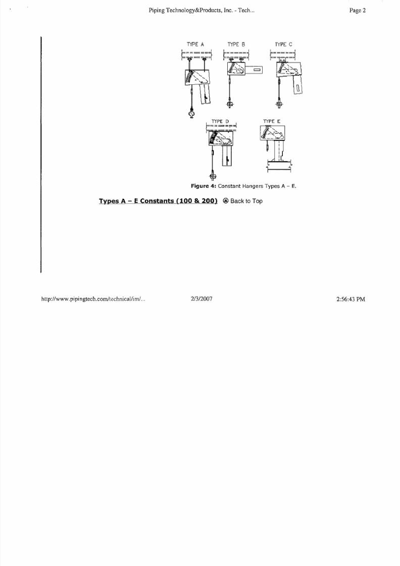
Topic Selection: Constant Spring Hangers It!Piping Technology & Products' constant spring hanger, usually referred to as aconstant, provides constant support force for pipes and equipment subjected tovertical movement due to thermal expansion at locations where maintaining a constant
stress is critical. This constant resistance is achieved by having two moment armspivoted about a common point. The load is suspended from one of these arms, and aspring is attached to the other. With an appropriate choice of moment arms and springproperties, a resisting force can be provided that is nearly independent of posit ion.Aswith variable springs, Type refers to the connection of the constant to the structure andthe pipe. Figure 4 shows the attachment for Types A - E. The designation Figure 100and 200 refer to the orientation of the spring can. This is vertical for Figure 100, andhorizontal for Figure 200.
Travel stops are installed in all constants before shipping. These must be present
during any hydro testing, but must be removed during installation before normaloperations. They are usually pins, but in some cases may be keys. See note below ontravel key removal. In either case, the load must be adjusted so that the travel stop iseasily removed.
Caution: Do not force the travel stops.
2/312007t tp://www.pipingtech.comltechnical/im/ ... 2:56:43 PM
8/4/2019 Spring Hanger Installation Information A
http://slidepdf.com/reader/full/spring-hanger-installation-information-a 2/10
Piping Technology&Products, Inc. - Tech...
TYPE A T Y P E B
Page 2
TY PE C
TY PE E
Figure 4: Constant HangersTypes A - E,
Types A - E Constants (100 & 200) @ Back to Top
hup:llwww.pipingtech.comflechnical/im/ ... 2/312007 2:56:43 PM

8/4/2019 Spring Hanger Installation Information A
http://slidepdf.com/reader/full/spring-hanger-installation-information-a 3/10
Piping Technology&Products, Inc. - Tech ... Page 3
A B c
Trovel Stop Pin
Figure 5: Travel stop posi tion.
1. Secure the hanger to a structure capable of handling the operating load, at a point where theconstant 's load coupl ing is direct ly over the desired point of at tachment to the pipe in theoperating position.
2. The moving parts of the constant should be unobstructed and free to move .3. Attach the connecting rod to the load coupl ing with fuf f thread engagement.
4. Transfer the load by turning on the load coupling before removing the t ravel stop.5. If required, hydro testing should be done at this time.
6. Once the load is transferred, the t ravel stop must be removed. The travel stop (painted red)should now slip out easily. If not, refer to Figure 5. The travel stop pin must be moved to thecenter of its hate by adjusting the hanger load. The hanger load needs to be increased if the
pin is in position A, or decreased if the pin is in position C. Once disengaged, the travel stopmay be stored by hanging it from the constant.
7. The hanger load should now be readjusted to the cold position.
8. When the operating conditions are reached, check the hanger to assure the indicator is at thehot posi tion. I f necessary, adjustment should be made by turning the toad coupl ing to al ign theindicator to the hot posit ion.
Type F - 100 Constants @ Back to Top
http://www.pipingtech.com/technicallim/ ... 2/312007 2:56:43 PM

8/4/2019 Spring Hanger Installation Information A
http://slidepdf.com/reader/full/spring-hanger-installation-information-a 4/10
Piping Technology&Products, Inc. - Tech ... Page 4
""'I-I"Tz
Figure 6: F - 200 Type constant, and Travel Stop Pin positions.
1. Secure base plate to the structure.
2. If the constant is of the platform type (see Fig. 6), place the pipe on the plat form, and at tach it
to the platform. It there is no platform, attach a strut to the piping, then to the constant support.
3. Hydro test l ine if necessary.
4. The travel stop should be in the middle of its hole. If the travel stop is in the A- conf iguration(see Fig. 5), contract the strut, and if i t is in the C- configurat ion, expand the strut to force the
travel stop pin to move to the center of the t ravel stop hole. When the travel stop pin is
centered in the travel stop holes, it can be easily removed and the constant is ready for
operation.
Danger!! If pin can not be easily removed after struts adjustment,
do not drive pin out.
http://www.pipingtech.com/technicallirn/ ... 2/312007 2:56:43 PM

8/4/2019 Spring Hanger Installation Information A
http://slidepdf.com/reader/full/spring-hanger-installation-information-a 5/10
Piping Technology&Products, Inc. - Tech ... Page 5
Iy_pe 200 - F @ Back to Top
The Type 200 - F constants are shipped with an Installation Rod and a Travel Stop Pin.
1. Attach the base plate of the constant to the support ing st ructure.
2. Attach the constant's support platform to the pipe using a pipe shoe or other suitable support. I fthe clearance is t ight, temporarily force the table down by tightening the instal la tion bolt (see
Fig. 7).3. Loosen the installation bolt or bolts to al low the load flange to rise up to the instal led height. I f
the clearance is loose, shim or grout the constant or pipe attachment accordingly.
4. Hydro test l ine if necessary.
5. If travel stop is in the A-configuration as shown in Fig. 5, extend the installation bolt (or bolts)
to force the load flange up so that the pin is in the center of its hole. If the pin is in the B
configurat ion, contract the insta llat ion bolts. When the travel stop pin is in the center of thetravel stop hole, i t can be easily removed.
6. Loosen and remove the instal lation bolt for the 200-F. The constant effort suppor t is now ready
for operation.
Instol.lotior'J Rod
1.
L_Tr- o vel Stop Pin
Figure 7: Type 200 - F
llP~_200 - U (Upthrust) Constants @ Back to Top
http.z/www.pipingtech.com/tcch nicallim/ ... 2/3/2007 2:56:43 PM
8/4/2019 Spring Hanger Installation Information A
http://slidepdf.com/reader/full/spring-hanger-installation-information-a 6/10
Piping Technology&Products, Inc. - Tech ... Page 6
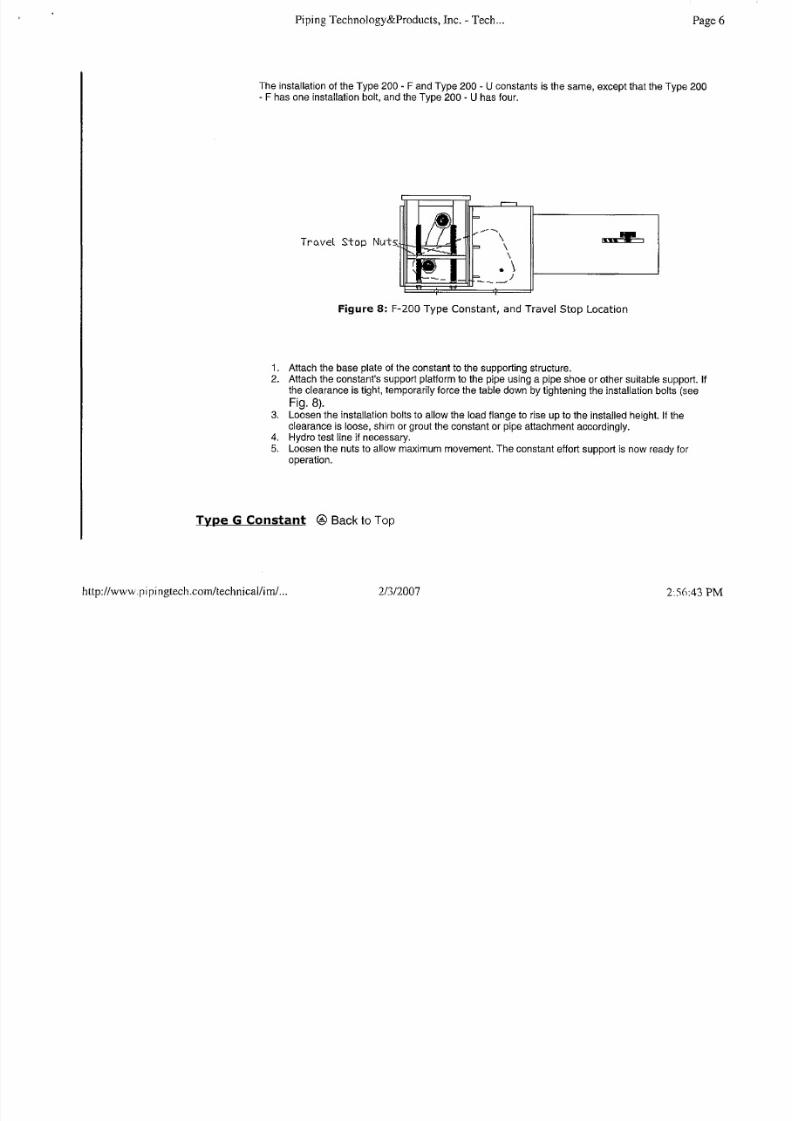
The installation of the Type 200 - F and Type 200 ~U constants is the same, except that the Type 200~F has one installation bolt, and the Type 200" U has four.
Tro.veL Stop
"- - - . . .\\
\
.\J~--
I 'W . "
Figure 8: F-200 Type Constant, and Travel Stop Location
1. At tach the base plate of the constant to the supporting st ructure.
2. At tach the constant's support plat form to the pipe using a pipe shoe or other sui table support. I f
the clearance is t ight, temporarily force the table down by tightening the instal la tion bolts (see
Fig. 8).
3. Loosen the installation bol ts to al low the load f lange to rise up to the installed height. I f theclearance is loose, shim or grout the constant or p ipe attachment accordingly.
4. Hydro test line if necessary.
5. Loosen the nuts to allow maximum movement. The constant effort support is now ready foroperation.
Type G Constant @ Back to Top
http://www.pipingtech.com/technicallim/ ... 2/3/2007 2" .5 ( ):43 PM

8/4/2019 Spring Hanger Installation Information A
http://slidepdf.com/reader/full/spring-hanger-installation-information-a 7/10
Piping Technology&Products, Inc. - Tech ... Page 7
The Type G constant consists of two Type 100 constants connected by a beam, withthe pipe being supported on the beam.
1. Support the pipe at the desi red elevat ion.
2. Attach load rods to the structural support.3. Attach the constant to the load rods using the turnbuckles provided.
4. Using the turnbuckles, level the pair of channels connecting the two constants.
5. Keeping the channels level, transfer the pipe load to the constant, either by raising the
constants or removing any temporary support for the pipe.
6. I f hydro testing is required, this should be done now.
7. Remove the travel stops. If they are not in the center of thei r holes, use the turnbuckles to
adjust the load so that the stops are in the center. They should be easi ly removed. If not,adjust the load until they are.
Do not drive them out.
8. Using the turnbuckles, adjust the load indicator to the cold posit ion.
9. After the load reaches normal operat ing condit ions, check to see that the load indicator is at
the hot position. If not, adjust with the turnbuckles.
1 IF------------=t------ ............---j
1-=--======--=-1
1 . Figure 9: GType Constant
http://www.pipingtech.comltechnicallirn/ ... 2/312007 2:56:43 PM

8/4/2019 Spring Hanger Installation Information A
http://slidepdf.com/reader/full/spring-hanger-installation-information-a 8/10
Piping Technology&Products, Inc. - Tech... Page 8
Field Instructions for LoadAdjustment, Fig. 100 & 200 @ Back to Top
Under no circumstances should an attempt be made to remove the lock nut and theload adjustment nut from the constant spring hanger.
Every constant spring hanger is calibrated in the factory and set to the load specifiedon the nameplate. Load adjustment in the field is discouraged as it may signif icantlychange the system.
However, to provide for situations where the supported load is different from thecalculated load, the constant spring hangers are equipped with load adjustmentcapability. The load adjustment capability consists of a load adjustment scale andindicator, which are used to increase (Figure 10A) or decrease (Figure 1~C), theload by 10%. Thus, a 2000-pound hanger can be adjusted for loads from 1800 to
2200 pounds. The travel stop pin must be engaged before load adjustment isperformed. Adjusting the load to higher or lower load from the load specified on thenameplate using load adjustment is approximate and not recommended.
To increase the cold setting be sure thatthe travel stop pin is in place. Then loosenthe lock nut at the end of the spring.
Tighten the main nut, then retighten thelock nut.
To decrease the cold setting be sure thatthe travel stoop pin is in place. Thenloosen the lock nut at the end of thespring. Loosen the main nut, thenretighten the lock nut.
http://www.pipingtech.com/technicalliml ... 2/312007 2:56:43 PM

8/4/2019 Spring Hanger Installation Information A
http://slidepdf.com/reader/full/spring-hanger-installation-information-a 9/10
Piping Technology&Products, Inc. - Tech ... Page 9
A t ]esign Loo.d + lO X
At DQ~ign Loo.cl
A i; ]esign L oo.d - 10%
Figure 10: Fieldadjustment for load. The LoadAdjustment Scale is located on the spring
can, near the adjustment nut.
Constant Hangers with Adjustable Travel Stop Keys: Removal of Travel Stop KE
@ Back to Top
http://www.pipingtech.com/technical/im/ ... 2/312007 2:56:43 PM

8/4/2019 Spring Hanger Installation Information A
http://slidepdf.com/reader/full/spring-hanger-installation-information-a 10/10
Piping Technology&Products, Inc. - Tech ... Page 10
8-FACE A-FACE
Honqer Pin
Figure 11: Adjustable Travel Stop Keys
1. After hanger instal lation, remove the t ravel stop hex nuts from both sides. Check whether A-
face or S-face of the threaded bol t is in constant with the travel stop keyhole as i llustrated in
Fig 11, above.2. If the 8-face of threaded bolt is in contact with the travel stop keyhole as shown in Figure 11,
turn the turnbuckle clockwise. The travel stop bolt wil l move towards the center. At this point,the load has been transferred and the constant hanger is balanced with the pipe weight . The
travel stop key can be easily removed.
3. If the A-face of threaded bolt is in contact with the travel stop keyhole as shown in Figure 11,
turn the turnbuckle counterclockwise. The travel stop bolt wil l move towards the center. At thispoint, the load has been transferred and the constant hanger is balanced with the pipe weight.
The travel stop key can be easily removed.
Home I Products I SeryiQ§,5.I Catalogs I Downloads I Technical I News I Site M _ g Q I Contact UsMailing: P.O. Box 34506, Houston, TX 77234-4506 Location: 3701 Holmes Road, Houston, TX 77051
Phone: (713) 731-0030 Q Toll Free: (800)787-5914 ~ FAX: (713) 731-8640 ~. E-MAIL: [email protected]
http://www.pipingtech.comitechnicallim/ ... 2/3/2007 2:56:43 PM