standards for radiation effects testing: ensuring
TRANSCRIPT

National Aeronautics and Space Administration
Standards for Radiation Effects Testing: Ensuring Scientific Rigor in
the Face of Budget Realities and Modern Device Challenges
Jean-Marie Lauenstein, NASA/GSFC
1To be presented by Jean-Marie Lauenstein at the Hardened Electronics and Radiation Technology (HEART) 2015 Conference, Chantilly, VA, April 21-24, 2015
Outline
• Space Radiation Environment• Radiation Effects• Test Standards & Guidelines
– Drivers for and against change• Examples• Conclusions
2To be presented by Jean-Marie Lauenstein at the Hardened Electronics and Radiation Technology (HEART) 2015 Conference, Chantilly, VA, April 21-24, 2015

THE SPACE RADIATION ENVIRONMENT AND EFFECTS
Part I:
3To be presented by Jean-Marie Lauenstein at the Hardened Electronics and Radiation Technology (HEART) 2015 Conference, Chantilly, VA, April 21-24, 2015
NOAA/SEC

High Energy Radiation Particles
• Deep-space missions may also see neutrons and gamma rays from background or radioisotope sources
4To be presented by Jean-Marie Lauenstein at the Hardened Electronics and Radiation Technology (HEART) 2015 Conference, Chantilly, VA, April 21-24, 2015
Trapped Particles:
Protons, Electrons, Heavy Ions
Galactic Cosmic Rays (GCRs)
Solar Protons
&
Heavier Ions
After J. Barth, 1997 IEEE NSREC Short Course; K. Endo, Nikkei Science Inc. of Japan; and K. LaBel private communication.

Radiation Effects
5To be presented by Jean-Marie Lauenstein at the Hardened Electronics and Radiation Technology (HEART) 2015 Conference, Chantilly, VA, April 21-24, 2015
• Destructive SEE—Poisson process, constant rate, affect single die; redundancy effective as mitigation but very costly
– SEL—Single-Event Latchup (Complementary Metal Oxide Semiconductor-CMOS)– SEGR—Single-Event Gate Rupture (High-field MOS devices)– SEB—Single-Event Burnout in discrete transistors and diodes– Others—Stuck Bits, Snapback (Silicon on Insulator), Single-Event Dielectric Rupture
• Nondestructive SEE—Poisson process, const. rate, single die, recoverable– SEU—Single-Event Upset in digital device (or portion of device)– MBU/MCU—Multibit/Multi-Cell Upset in digital device (or portion)– SET—Single-Event Transient in digital or analog device– SEFI—Single-Event Functional Interrupt (full or partial loss of functionality)
• Degradation Mechanisms—cumulative, end-of-life, affect most die as mission approaches mean failure dose; redundancy ineffective
• TID—Total Ionizing Dose (degradation due to charge trapped in device oxides)• DDD—Displacement Damage Dose (degradation from damage to
semiconductor)
*SEE: Single-event effect
TEST STANDARDSPart II:
6To be presented by Jean-Marie Lauenstein at the Hardened Electronics and Radiation Technology (HEART) 2015 Conference, Chantilly, VA, April 21-24, 2015
U.S. Departmentof Defense
ANSIAmerican National Standards Institute
ASTM
JEDEC
ESCCEuropean Space
Components Coordination
IEC

Key Space Radiation Test Standards
Standard Title DateJEDEC JESD57
Test Procedures for the Measurement of SEE in Semiconductor Devices from Heavy-Ion Irradiation
1996
JEDEC JESD234
Test Standard for the Measurement of Proton Radiation SEE in Electronic Devices
2013
MIL-STD-750-1
Environmental Test Methods for Semiconductor DevicesTM 1017: Neutron irradiationTM 1019: Steady-state total dose irradiation procedureTM 1080: SEB and SEGR
2014
MIL-STD-883 MicrocircuitsTM 1017: Neutron irradiationTM 1019: Ionizing radiation (total dose) test procedure
2014
ESA-ESCC-25100
SEE Test Method and Guidelines 2014
ESA-ESCC-22900
Total Dose Steady-state Irradiation Test Method 2010
7To be presented by Jean-Marie Lauenstein at the Hardened Electronics and Radiation Technology (HEART) 2015 Conference, Chantilly, VA, April 21-24, 2015
(Prompt dose and terrestrial radiation standards not included)
*TM = Test Method

Space Radiation Test GuidelinesStandard Title DateASTM F1192 Standard Guide for the Measurement of Single Event
Phenomena (SEP) Induced by Heavy Ion Irradiation of Semiconductor Devices
2011
ASTM F1892 Standard Guide for Ionizing Radiation (Total Dose) Effects Testing of Semiconductor Devices
2012
ASTM F1190 Practice for the Neutron Irradiation of Unbiased Electronic Components
2011
MIL-HDBK-814 Ionizing Dose and Neutron Hardness Assurance Guidelinesfor Microcircuits and Semiconductor Devices
1994
Sandia Nat’l Lab.SAND 2008-6983P
Radiation Hardness Assurance Testing ofMicroelectronic Devices and Integrated Circuits: Test Guideline for Proton and Heavy Ion SEE
2008
Sandia Nat’l Lab.SAND 2008-6851P
Radiation Hardness Assurance Testing ofMicroelectronic Devices and Integrated Circuits:Radiation Environments, Physical Mechanisms, and Foundations for Hardness Assurance
2008
NASA/ DTRA Field Programmable Gate Array (FPGA) Single Event Effect (SEE) Radiation Testing
2012
8To be presented by Jean-Marie Lauenstein at the Hardened Electronics and Radiation Technology (HEART) 2015 Conference, Chantilly, VA, April 21-24, 2015
(See ASTM website for additional guidelines)

Standard Rationale
9To be presented by Jean-Marie Lauenstein at the Hardened Electronics and Radiation Technology (HEART) 2015 Conference, Chantilly, VA, April 21-24, 2015
• Standards & Guidelines are developed/revised to: – Ensure tests follow best practices– Ensure results from different vendors/testers are comparable– Minimize and bound systematic and random errors
Data must be meaningful and must facilitatepart selection and risk analysis
Best practices must be disseminated to new members of the test community

The Time Lag
10To be presented by Jean-Marie Lauenstein at the Hardened Electronics and Radiation Technology (HEART) 2015 Conference, Chantilly, VA, April 21-24, 2015
• Test standards & guidelines can (and often do) take years to develop or revise– Widespread compliance can take additional years
• Technology & research continuously evolve
Cartoon credits:www.pixshark.com
The time lag is both useful and problematic
Test Standards Technology

Balancing Act
11To be presented by Jean-Marie Lauenstein at the Hardened Electronics and Radiation Technology (HEART) 2015 Conference, Chantilly, VA, April 21-24, 2015
• 4 drivers of development/revision:– New technologies requiring new methods for testing– New failure mechanisms or new research on known mechanisms– New radiation hardness assurance methods – New applications of existing technology
• 4 counterbalances to change:– Cost (time and money)– Consensus/weight of evidence– Device complexity (note: can push both ways)– Pre-existing products and designs
Standards Tug-of-War
Update Reaffirm

Example 1: ELDRS• ELDRS = Enhanced Low Dose Rate Sensitivity
– Amount of total dose degradation at a given total dose is greater at low dose rates (LDR) than at high dose rates (HDR)
• Low dose rate enhancement factor (LDR EF)LDR EF =
• MIL-STD-883G TM 1019: part is ELDRS susceptible if LDR EF ≥ 1.5 and parameter is above pre-irradiation specification limits
12To be presented by Jean-Marie Lauenstein at the Hardened Electronics and Radiation Technology (HEART) 2015 Conference, Chantilly, VA, April 21-24, 2015
Rate DoseHigh ΔParameterRate Dose Low ΔParameter
M. R. Shaneyfelt, et al., IEEE TNS, 2000.
IB+ vs. Total Dose for LM111 Voltage Comparators

Example 1: ELDRS in LM117• History: LM117 deemed “ELDRS free” under MIL-STD-883
TM1019 Condition D:– ≤ 10 mrad(Si)/s dose rate for bipolar or BiCMOS linear or mixed-
signal devices• Driver for change: new research on known mechanisms
– Exhibits increasing degradation with decreasing dose rates < 10 mrad(Si)/s – “Ultra ELDRS” : parameter out of spec at LDR ≤ 1 mrad(Si)/s
13To be presented by Jean-Marie Lauenstein at the Hardened Electronics and Radiation Technology (HEART) 2015 Conference, Chantilly, VA, April 21-24, 2015
www.ti.comChen, D., et al., IEEE TNS 2011; updated 2015.

Example 1: ELDRS cont’d
• Ultra-ELDRS is not isolated to LM117:
14To be presented by Jean-Marie Lauenstein at the Hardened Electronics and Radiation Technology (HEART) 2015 Conference, Chantilly, VA, April 21-24, 2015
From Pease, R.L., IEEE TNS, 2009
Should the test standard be revised?

Example 1: ELDRS cont’d
• Challenges for hardness assurance– Applying a constant overtest factor to the specification dose
for a 10 mrad(Si)/s irradiation test may not bound the degradation for all parts
• No easy solution– Test at the mission required dose rate?– Test at a dose rate lower than 10 mrad(Si)/s?
• Counterbalance: – Cost: Already takes 2 months for 50 krad(Si) at 10 mrad(Si)/s– Consensus: Significance of risk still under debate– Pre-existing products and designs:
• Retest/requal costs, • Ability to track lot-lot variations lost until history developed
under new test conditions
15To be presented by Jean-Marie Lauenstein at the Hardened Electronics and Radiation Technology (HEART) 2015 Conference, Chantilly, VA, April 21-24, 2015

Example 2: More ELDRS• MIL-STD-750-1 TM1019: No “Condition D” low dose rate req’ts• History: Discrete bipolar junction transistors (BJTs) do not
exhibit ELDRS• Driver for change: new research on known mechanisms
– Some discrete BJTs demonstrate ELDRS of current gain degradation
• Radiation Hardness Assurance (RHA) challenge: ELDRS for BJTs of similar process technology varies widely
• Counterbalance: Cost, consensus, and pre-existing devices– How widespread is the susceptibility?
16To be presented by Jean-Marie Lauenstein at the Hardened Electronics and Radiation Technology (HEART) 2015 Conference, Chantilly, VA, April 21-24, 2015
D. Chen, et al., IEEE REDW, 2012.
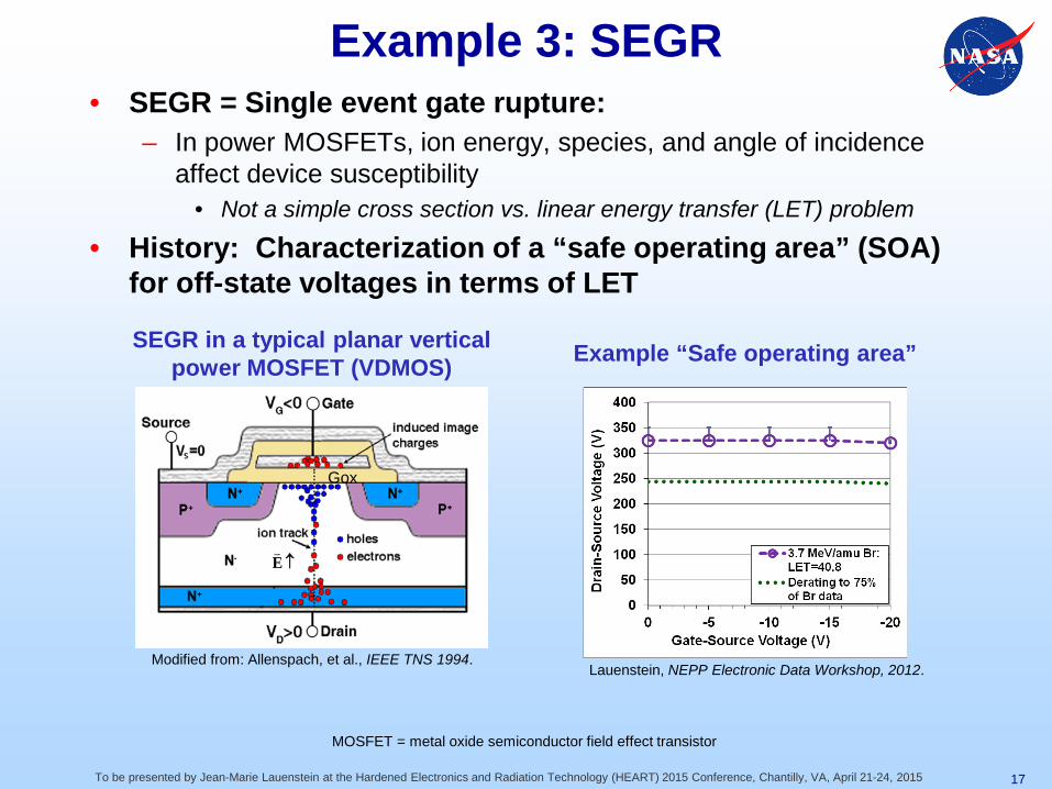
Example 3: SEGR• SEGR = Single event gate rupture:
– In power MOSFETs, ion energy, species, and angle of incidence affect device susceptibility
• Not a simple cross section vs. linear energy transfer (LET) problem
• History: Characterization of a “safe operating area” (SOA) for off-state voltages in terms of LET
17To be presented by Jean-Marie Lauenstein at the Hardened Electronics and Radiation Technology (HEART) 2015 Conference, Chantilly, VA, April 21-24, 2015
↑E
Gox
SEGR in a typical planar vertical power MOSFET (VDMOS) Example “Safe operating area”
Modified from: Allenspach, et al., IEEE TNS 1994.Lauenstein, NEPP Electronic Data Workshop, 2012.
MOSFET = metal oxide semiconductor field effect transistor

Example 3: SEGR cont’d• Driver for change: new research on known mechanisms
– 1996: ion penetration range (energy) affects susceptibility– 2001: worst-case energy for given ion defined
• MIL-STD-750E (2006) incorporates this effect:“Data points are taken to describe the response of the discrete MOSFET as a function of VGS and/or VDS over the operating range of the device and/or over a range of LET values.” Later in the test procedure: “Also, note that the energy of the ion beam has been shown to influence the SEGR failure thresholds. Therefore, determination of the worst case test condition can require multiple irradiations with the same ion at different energies.”
18To be presented by Jean-Marie Lauenstein at the Hardened Electronics and Radiation Technology (HEART) 2015 Conference, Chantilly, VA, April 21-24, 2015
Energy (Range) Effects on SOA • Impact to pre-existing devices:– “SOA” relabeled as “Single Event
Effect Response Curve” for a given beam condition.
– Worst-case test condition still not adopted due to cost of re-qual
Lauenstein, NEPP Electronic Data Workshop, 2012.

Example 3: SEGR cont’d• Driver for further change: Multiple manufacturers
– Different device geometries demand true worst-case beam conditions for cross-manufacturer comparisons
• MIL-STD-750-1 (2012) incorporates worst-case conditions:“For SEGR, the worst-case test condition for the ion occurs when the ion fully penetrates the epitaxial layer(s) with maximum energy deposition through the entire epitaxial layer(s).”“NOTE 23: SEGR characterization curves may be better expressed as a function of ion species (atomic number) instead as a function of LET. Ion beam characteristics shall be included with the response curves (ion LET at die surface, ion species, and ion energy).
19To be presented by Jean-Marie Lauenstein at the Hardened Electronics and Radiation Technology (HEART) 2015 Conference, Chantilly, VA, April 21-24, 2015
• Impact to pre-existing devices:– Requalification– Oldest generation no longer
advertised for space applications • JESD57 (1996) still LET-based
– Under revision
Liu, et al., IEEE TNS, 2010.
Worst-case ion energy: Beam 2

Example 4: more SEGR• Driver: New application of existing technology
– Demand for rate estimation when risk avoidance not possible• ex/ high-performance applications or commercial boards
• Counterbalance: Lack of consensus on failure rate prediction methods – 6 proposed methods in the literature – none validated– Require different kinds of test data
20To be presented by Jean-Marie Lauenstein at the Hardened Electronics and Radiation Technology (HEART) 2015 Conference, Chantilly, VA, April 21-24, 2015
Operating Outside the “SOA”Requires Failure Rate Estimation
Lauenstein, et al., IEEE NSREC 2014

Example 5: Advanced Electronics• History: SEE test guidelines and standards geared toward
simpler devices/circuits• Driver for change: New technologies, failure modes, & research
– Proton direct-ionization induced SEE– Variation of susceptibility with roll angle in addition to tilt angle– Expansion of single-event functional interrupt definition– High-speed applications (require high-speed test capability)– Increasing number of modes of operation of complex devices– ....
21To be presented by Jean-Marie Lauenstein at the Hardened Electronics and Radiation Technology (HEART) 2015 Conference, Chantilly, VA, April 21-24, 2015
K. M. Warren, et al., IEEE TNS, 2007
Effective LET not effective for 90 nm CMOS latch
D. F. Heidel, et al., IEEE TNS, Dec. 2008.
Low-energy protons upset 65 nm Silicon-on-Insulator SRAM
*SRAM = static random-access memory

Example 5: Advanced Electronics• Counterbalance: Cost, complexity• How do we incorporate advanced electronics SEE testing into
SEE test standards?– Proton SEE test standard (JESD234) released– Revision of JESD57 is an opportunity for inclusion of more
established methods for testing advanced electronics– Highly complex technologies will benefit from specific guidelines
• ex/ NASA FPGA test guideline
– Complex devices incorporate many modes and functions• Test results depend on how we test the device• The bleeding edge of testing is generalizing application specific
test results to bound flight performance at all stages of the mission
22To be presented by Jean-Marie Lauenstein at the Hardened Electronics and Radiation Technology (HEART) 2015 Conference, Chantilly, VA, April 21-24, 2015
High-Speed Test Fixture
Photo credit: J. A. Pellish, NASA GSFC, 2013

Summary
• Because radiation hardness assurance is dynamic, test standards and guidelines will always be “behind the times”
• Continued development of test standard/guideline updates facilitates technical rigor and mission confidence and success
But…• Test standards are a compromise between technical
rigor and economic realities– The goal is to be good enough to ensure success and cheap
enough that the standards & guidelines will actually be used
23To be presented by Jean-Marie Lauenstein at the Hardened Electronics and Radiation Technology (HEART) 2015 Conference, Chantilly, VA, April 21-24, 2015