steper motor control through wireless
TRANSCRIPT
STEPPER MOTOR CONTROL THROUGH WIRELESS
Submitted by
(RAVI KUMAR,ASHWANI GARG,VINOD KUMAR,MANOJ GOSWAMI.VIBHOOTI KUMAR SINHA)FOURTH YEAR
ELECTRONICS & TELECOMMUNICATION
Guided by
Mr. Aman dua , Mrs. Shiva JaiswalLECTURER
(ELECTRONICS & TELECOMMUNICATION)
COLLEGE OF ENGINEERING ROORKEEROORKEE – 247 667

ACKNOWLEDGEMENTSACKNOWLEDGEMENTS
We express our deepest thanks toWe express our deepest thanks toMr. AMAN DUA Mr. AMAN DUA
Project GuideProject Guide LecturerLecturer Ms.DIVYA ARORAMs.DIVYA ARORA
Project CoordinatorProject Coordinator , , LecturerLecturer
Mr. B D PATELMr. B D PATEL Head of Electronics & Telecom DeptHead of Electronics & Telecom Dept
College of Engineering Roorkee ,RoorkeeCollege of Engineering Roorkee ,Roorkee

OUR PROJECTOUR PROJECT
OBJECTIVE-:To control stepper motor by OBJECTIVE-:To control stepper motor by computer interface as well as by wirelesscomputer interface as well as by wireless
INTRODUCTION-:Project is based on INTRODUCTION-:Project is based on 1)microcontroller programming 1)microcontroller programming
2)driver circuit interface with micro-controller 2)driver circuit interface with micro-controller
3)interfacing of keyboard3)interfacing of keyboard
4) interfacing of wireless control4) interfacing of wireless control
5)LCD deployment to watch change in speed5)LCD deployment to watch change in speed

stepper motor performance stepper motor performance characteristiccharacteristic
Rotation in both directionsRotation in both directions
Precision angular incremental changesPrecision angular incremental changes
Repetition of accurate motion Repetition of accurate motion
A holding torque at zero speed A holding torque at zero speed
Capability for digital control.Capability for digital control.
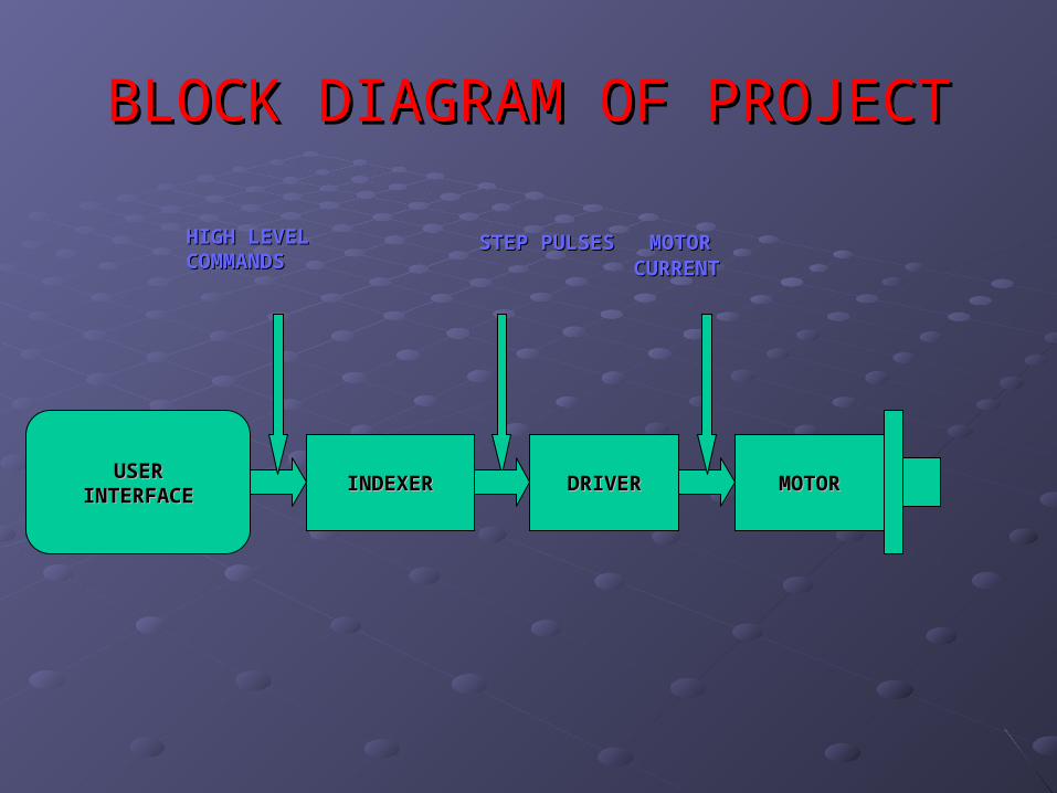
BLOCK DIAGRAM OF PROJECTBLOCK DIAGRAM OF PROJECT
USERUSERINTERFACEINTERFACE INDEXERINDEXER DRIVERDRIVER MOTORMOTOR
HIGH LEVELHIGH LEVELCOMMANDSCOMMANDS
STEP PULSESSTEP PULSES MOTOR MOTOR CURRENTCURRENT

Specification of the project Specification of the project modelmodel
IndexerIndexer is a micro-controller(AT89C51 ) is a micro-controller(AT89C51 )
DriverDriver (ULN2803A ) converts the indexer (ULN2803A ) converts the indexer command signals into the power necessary to command signals into the power necessary to energize the motor windingsenergize the motor windings
Step Motor(UNIPOLAR)Step Motor(UNIPOLAR) is an electromagnetic is an electromagnetic device that converts digital pulses into device that converts digital pulses into mechanical shaft rotation mechanical shaft rotation
Computer Interfacing (serial port)Computer Interfacing (serial port)
LCDLCD

STEPPER MOTORSTEPPER MOTOR
BrushlessBrushlessSynchronous electric motorSynchronous electric motordivide a full rotation into a large number of divide a full rotation into a large number of stepssteps stepper motor uses an open loop with no stepper motor uses an open loop with no feedback, position being determined by a feedback, position being determined by a software counter in the controlling software counter in the controlling computer. computer. Rotation in both directions Rotation in both directions

INTERNAL STRUCTURE OF STEPPER MOTOR
F=i (dl x B)
ROTOR (permanent magnet)
TEETH (to define precise rotation
STATOR(carry coil for current Flow)

How stepper motor works?How stepper motor works?
Stepper motor converts electrical pulses into specific rotational movements
Hence ,Torque is generated by alternately magnetizing the stator teeth electrically, and permanent magnet rotor teeth try to align up with stator teeth

One Phase Steps


One Phase On Mode (Full Step mode)

One Phase On Steps Sequence

MICROCONTROLLERMICROCONTROLLER
Special purpose computers Special purpose computers
Dedicated to one task (i.e. no multi Dedicated to one task (i.e. no multi tasking)tasking)
Low-power device.Low-power device.
It has a dedicated input device.It has a dedicated input device.
In our project we are using AT89C51 In our project we are using AT89C51 MICROCONTROLLER MICROCONTROLLER
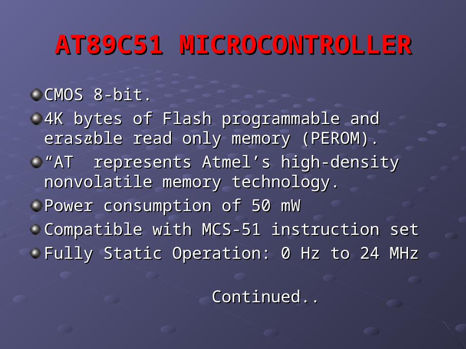
AT89C51 MICROCONTROLLERAT89C51 MICROCONTROLLER
CMOS 8-bit.CMOS 8-bit.
4K bytes of Flash programmable and erasable 4K bytes of Flash programmable and erasable read only memory (PEROM). read only memory (PEROM).
““AT” represents Atmel’s high-density nonvolatile AT” represents Atmel’s high-density nonvolatile memory technology.memory technology.
Power consumption of 50 mWPower consumption of 50 mW
Compatible with MCS-51 instruction setCompatible with MCS-51 instruction set
Fully Static Operation: 0 Hz to 24 MHzFully Static Operation: 0 Hz to 24 MHz
Continued..Continued..

Continued..Continued..
128 x 8-Bit Internal RAM128 x 8-Bit Internal RAM Two 16-Bit Timer/CountersTwo 16-Bit Timer/Counters Six Interrupt SourcesSix Interrupt Sources 32 Programmable I/O Lines32 Programmable I/O Lines

ULN 2803 DRIVERULN 2803 DRIVER
suited for interfacing between low-level suited for interfacing between low-level logic circuitry and multiple peripheral logic circuitry and multiple peripheral power loadspower loads
USERUSERINTERFACEINTERFACE
INDEXERINDEXER DRIVERDRIVER MOTORMOTOR
HIGH LEVELHIGH LEVELCOMMANDSCOMMANDS
STEP STEP PULSESPULSES
MOTOR MOTOR CURRENTCURRENT

Internal architecture of ULN2803Internal architecture of ULN2803
Seven open collector darlington pairs with Seven open collector darlington pairs with common emitters .common emitters .
500mA to each of the seven drivers , Output 500mA to each of the seven drivers , Output voltage to 95 V .voltage to 95 V .
power loads totaling over 230 W we can connect power loads totaling over 230 W we can connect to it.to it.
Each channel rated at 500mAand can withstand Each channel rated at 500mAand can withstand peak currents of 600mA(i.e. it is highly reliable) peak currents of 600mA(i.e. it is highly reliable)
TTL, DTL, PMOS or CMOS-Compatible Inputs TTL, DTL, PMOS or CMOS-Compatible Inputs

REGULATORREGULATOR
LM78XX LM78XX
available in the TO-220/D-PAK package available in the TO-220/D-PAK package
fixed output voltages fixed output voltages
thermal shut down and safe operating area thermal shut down and safe operating area protection protection
Output Current up to 1A Output Current up to 1A
Output Voltages of 5, 6, 8, 9, 10, 12, 15, 18, 24V Output Voltages of 5, 6, 8, 9, 10, 12, 15, 18, 24V
Short Circuit Protection Short Circuit Protection

LIQUID CRYSTAL DISPLAYLIQUID CRYSTAL DISPLAY
Hitachi's HD44780 Hitachi's HD44780
It has 1 controller with14 Pins It has 1 controller with14 Pins
configurations of 8x1 characters, 16x2, configurations of 8x1 characters, 16x2, and 20x4 . The largest such configuration and 20x4 . The largest such configuration is 40x4 characters.we are using 8x1 LCDis 40x4 characters.we are using 8x1 LCD

IC CD40106
HEX Schmitt Trigger (NOT Gate)
Features
• Wide supply voltage range:3V to 15V
• High noise immunity: 0.7VDD
• Low power TTL compatibility
• Hysteresis 0.4VDD & 0.2VDD guaranteed
• Hysteresis 0.4VDD & 0.2VDD guaranteed
9
7-
8
+
14

COMPUTER INTERFACINGCOMPUTER INTERFACING
We can connect our project to serial port We can connect our project to serial port of computer and can control the speed of it of computer and can control the speed of it using keyboard.using keyboard.Serial portsSerial ports areare typically identified on IBM typically identified on IBM compatible computers as COM ports compatible computers as COM ports It folllows synchronous data link It folllows synchronous data link standard(RS 232)standard(RS 232)serial communicationserial communication is the process of is the process of sending data sending data one bit at one timeone bit at one time

SERIAL Vs PARALLEL COMM.SERIAL Vs PARALLEL COMM.
TRANSCEIVERTRANSCEIVER
transceivertransceiver is a device that has both a is a device that has both a transmittertransmitter and a and a receiverreceiver
An electronic switch allows the transmitter and An electronic switch allows the transmitter and receiver to be connected to the same antenna. receiver to be connected to the same antenna.
it is impossible to receive signals while it is impossible to receive signals while transmitting (called half duplex comm. )transmitting (called half duplex comm. )
Some transceivers are designed to allow Some transceivers are designed to allow reception of signals during transmission periods reception of signals during transmission periods (called full duplex comm.) (called full duplex comm.) contd..contd..

contd..contd..
A logic 0 is represented voltage +3V to +15VDC A logic 0 is represented voltage +3V to +15VDC and a logic 1 is represented by -3VDC to -and a logic 1 is represented by -3VDC to -15VDC.15VDC.
250kbps Operation250kbps Operation
Low Power: 60mW Low Power: 60mW
RS232 CompatibleRS232 Compatible
High Impedance High Impedance
State When Off or State When Off or
Powered Down Powered Down

This PROJECT can be used perfectly in many areas.This PROJECT can be used perfectly in many areas.
This device is easy to implement in hardware and software means.This device is easy to implement in hardware and software means.
This circuit is cost effective, consume less power and take minimum This circuit is cost effective, consume less power and take minimum space.space.
CONCLUSION
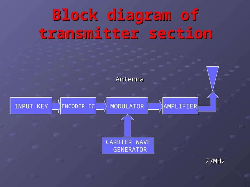
Block diagram of transmitter Block diagram of transmitter sectionsection
AntennaAntenna
27MHz27MHz
AMPLIFIERMODULATORENCODER ICINPUT KEY
CARRIER WAVE GENERATOR
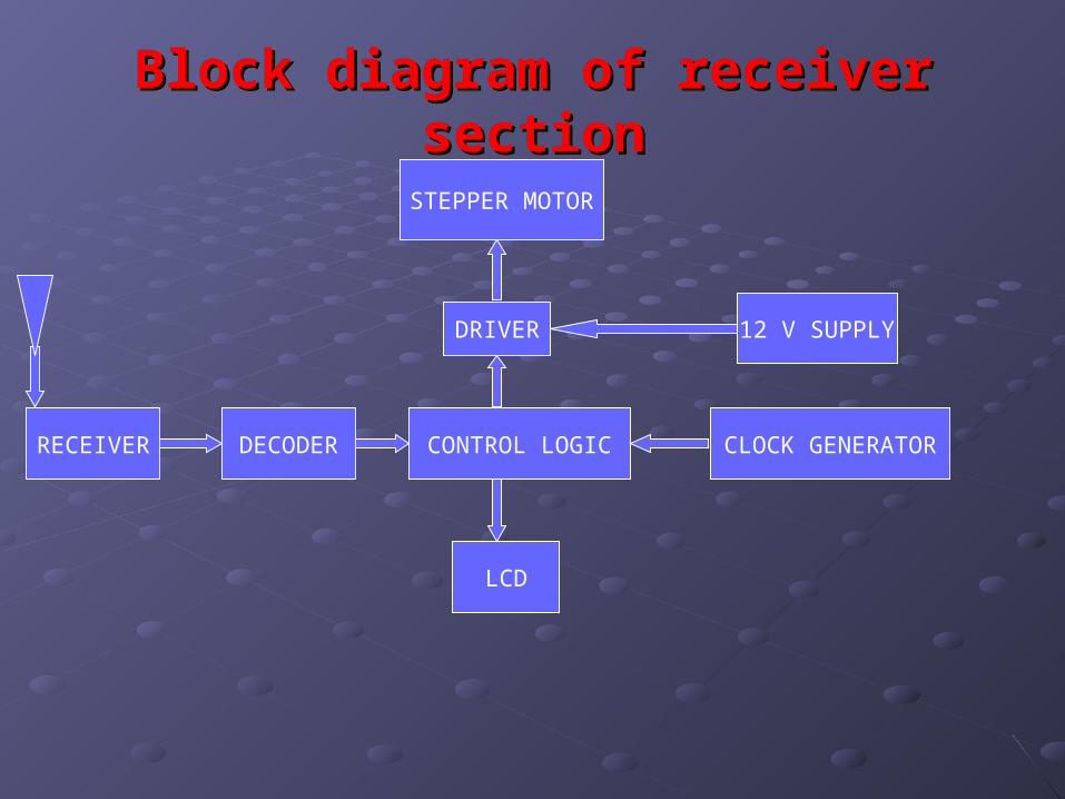
Block diagram of receiver sectionBlock diagram of receiver section
CLOCK GENERATORCONTROL LOGICDECODERRECEIVER
STEPPER MOTOR
DRIVER
LCD
12 V SUPPLY

PROJECT COMPONENTSPROJECT COMPONENTS
MICRO CONTROLLERAT89C51
TRANCEIVERMAX 232 N
ULN2803ADRIVER
REGULATORLM7805
STEPPER MOTOR
POTENTIOMETER TRANSFORMER
CLOCK GENERATORCD40106
LCDHD44780

FUTURE OF OUR PROJECTFUTURE OF OUR PROJECT
Places where we need precise position to Places where we need precise position to be displaced E.g.:be displaced E.g.:
1)Machine tools1)Machine tools
2)Disk drives (Hard disk, Floppy Drive)2)Disk drives (Hard disk, Floppy Drive)
3)Printers3)Printers
4)Robotics4)Robotics

THE ENDTHE END
THANKS YOU ALLTHANKS YOU ALL