storebest schwerlastregal "slr"
DESCRIPTION
12.000 kg Feldlast, 6 Meter Bauhöhe, 266 cm Achsmaß, Temperaturen von minus 5 Grad C! Unser Schwerlastregal SLR hält was es verspricht. Und das ohne aufwendiges Zusammenbauen mit Schrauben bei der Montage. Auch die Tragbalken können schraubenlos verstellt werden. Sie brauchen nur einen Sicherungsstift einrasten und alles ist sicher. Ein besonderer Vorteil für Sie ist die Konstruktion nach dem Baukastenprinzip. Sie können unser Grundregal, sowie das Depotregal in das SLR einbauen. Alle drei Systeme sind voll kompatibel miteinander.TRANSCRIPT
1
Ausgabe/ Is
sue/ E
ditio
n 0
7-2
008
ProjektbeispieleProject Examples
Exemples de projet
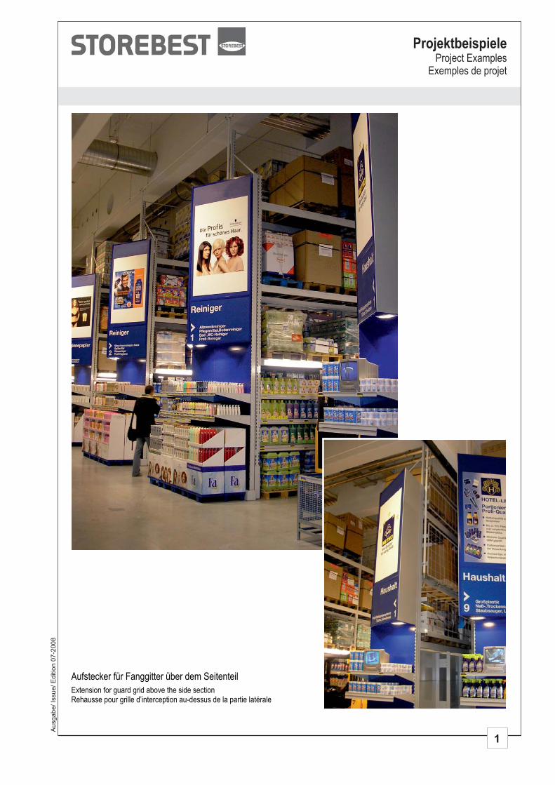
Aufstecker für Fanggitter über dem Seitenteil
Extension for guard grid above the side sectionRehausse pour grille d’interception au-dessus de la partie latérale
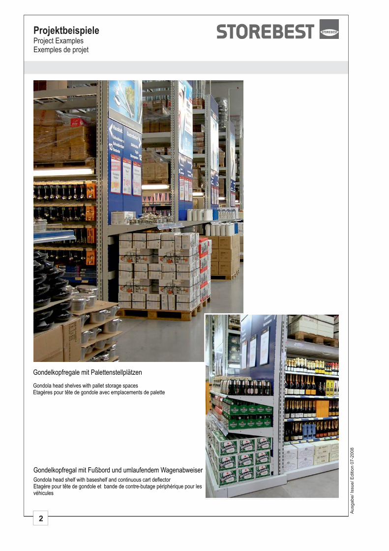
Gondelkopfregal mit Fußbord und umlaufendem Wagenabweiser
Gondola head shelf with baseshelf and continuous cart deflectorEtagère pour tête de gondole et bande de contre-butage périphérique pour lesvéhicules
Gondelkopfregale mit Palettenstellplätzen
Gondola head shelves with pallet storage spacesEtagères pour tête de gondole avec emplacements de palette
2
ProjektbeispieleProject ExamplesExemples de projet
Ausgabe/ Is
sue/ E
ditio
n 0
7-2
008
3
Ausgabe/ Is
sue/ E
ditio
n 0
7-2
008
ProjektbeispieleProject Examples
Exemples de projet
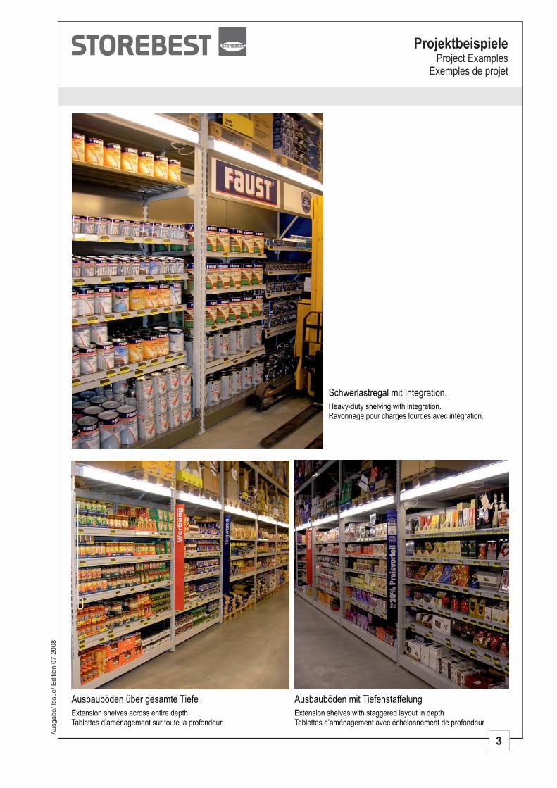
Schwerlastregal mit Integration.
Heavy-duty shelving with integration.Rayonnage pour charges lourdes avec intégration.
Ausbauböden über gesamte Tiefe
Extension shelves across entire depthTablettes d’aménagement sur toute la profondeur.
Ausbauböden mit Tiefenstaffelung
Extension shelves with staggered layout in depthTablettes d’aménagement avec échelonnement de profondeur
4
ProjektbeispieleProject ExamplesExemples de projet
Ausgabe/ Is
sue/ E
ditio
n 0
7-2
008
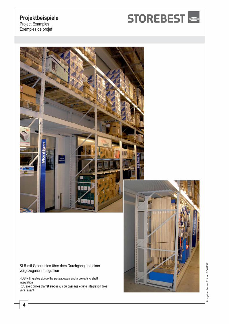
SLR mit Gitterrosten über dem Durchgang und einervorgezogenen Integration
HDS with grates above the passageway and a projecting shelfintegrationRCL avec grilles d'arrêt au-dessus du passage et une integration tiréevers l’avant
5
ProjektbeispieleProject Examples
Exemples de projet
Ausgabe/ Is
sue/ E
ditio
n 0
7-2
008
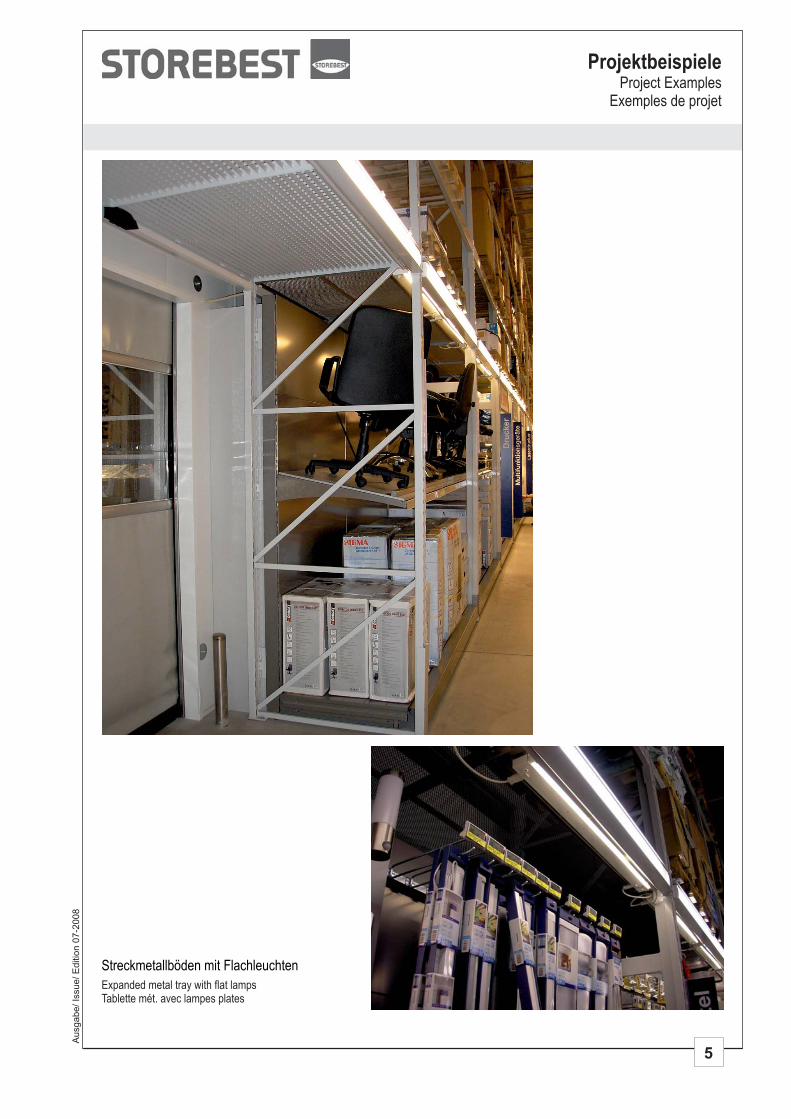
Streckmetallböden mit Flachleuchten
Expanded metal tray with flat lampsTablette mét. avec lampes plates
6
ProjektbeispieleProject ExamplesExemples de projet
Ausgabe/ Is
sue/ E
ditio
n 0
7-2
008
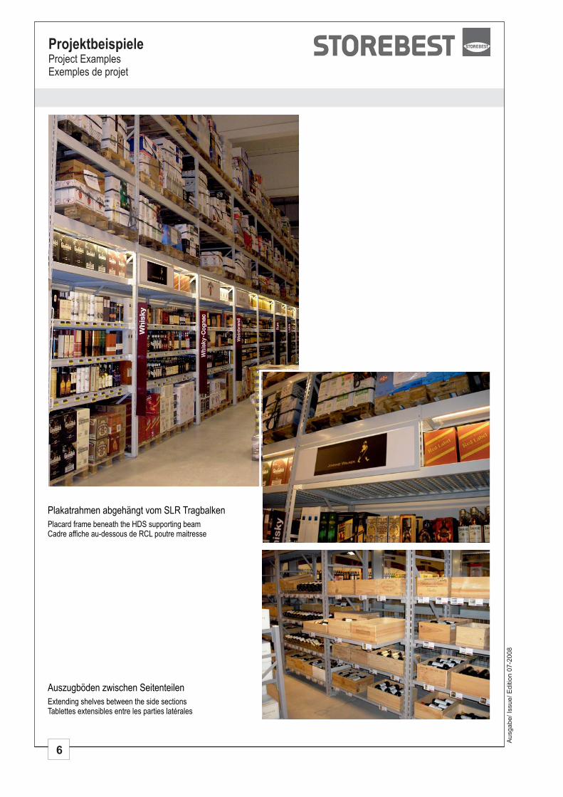
Auszugböden zwischen Seitenteilen
Extending shelves between the side sectionsTablettes extensibles entre les parties latérales
Plakatrahmen abgehängt vom TragbalkenSLR
Placard frame beneath the HDS supporting beamCadre affiche au-dessous de RCL poutre maitresse
Ausgabe/ Is
sue/ E
ditio
n 0
7-2
008
ProjektbeispieleProject Examples
Exemples de projet
7
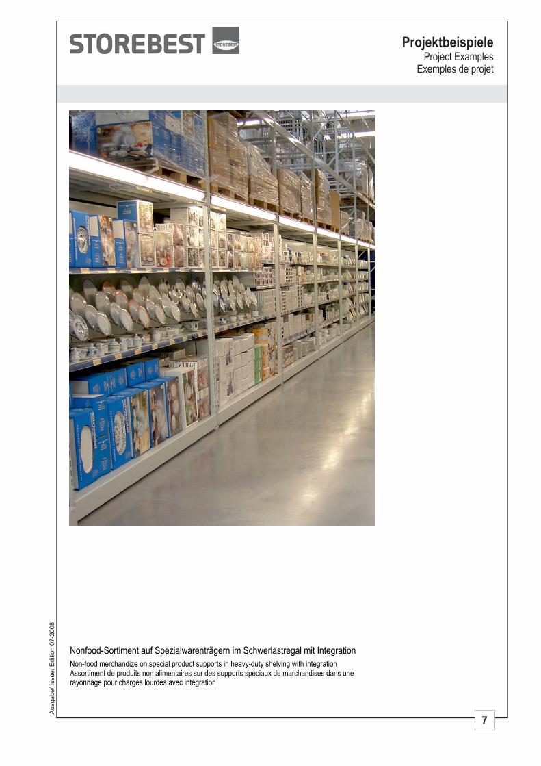
Nonfood-Sortiment auf Spezialwarenträgern im Schwerlastregal mit Integration
Non-food merchandize on special product supports in heavy-duty shelving with integrationAssortiment de produits non alimentaires sur des supports spéciaux de marchandises dans unerayonnage pour charges lourdes avec intégration
8
ProjektbeispieleProject ExamplesExemples de projet
Ausgabe/ Is
sue/ E
ditio
n 0
7-2
008
Aus
gabe
/ Iss
ue/ E
ditio
n 07
-200
839 Schwerlastregal SLR
39 Heavy -Duty Shelving HDS39 Rayonnage pour charges lourdes RCL
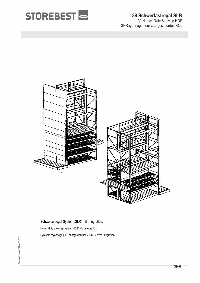
Schwerlastregal-System „SLR“ mit Integration.
Heavy-duty shelving system “HDS” with integration.
Système rayonnage pour charges lourdes « RCL » avec intégration.
39-01
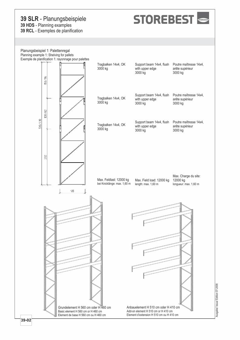
Anbauelement H 510 cm oder H 410 cmAdd-on elementElement d’extension
H 510 cm or H 410 cmH 510 cm ou H 410 cm
Planungsbeispiel 1: PalettenregalPlanning example 1: Shelving for palletsExemple de planification 1: rayonnage pour palettes
39 SLR - Planungsbeispiele39 HDS39 RCL
- Planning examples- Exemples de planification
Aus
gabe
/ Iss
ue/ E
ditio
n 07
-200
8
Tragbalken 14x4, OK3000 kg
Tragbalken 14x4, OK3000 kg
Tragbalken 14x4, OK3000 kg
Max. Feldlast: 12000 kgbei Knicklänge: max. 1,60 m
Support beam 14x4, flushwith upper edge3000 kg
Support beam 14x4, flushwith upper edge3000 kg
Support beam 14x4, flushwith upper edge3000 kg
Max. Field load: 12000 kglength: max. 1,60 m
Poutre maîtresse 14x4,arête supérieur3000 kg
Poutre maîtresse 14x4,arête supérieur3000 kg
Poutre maîtresse 14x4,arête supérieur3000 kg
Max. Charge du site:12000 kglongueur: max. 1,60 m
39-02
Grundelement H 560 cm oder H 460 cmBasic elementElement de base
H 560 cm or H 460 cmH 560 cm ou H 460 cm
Aus
gabe
/ Iss
ue/ E
ditio
n 07
-200
8
39-03
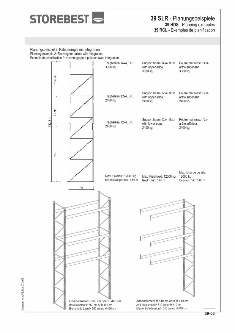
Tragbalken 14x4, OK3000 kg
Tragbalken 12x4, OK2400 kg
Tragbalken 12x4, UK2400 kg
Max. Feldlast: 12000 kgbei Knicklänge: max. 1,60 m
Support beam 14x4, flushwith upper edge3000 kg
Support beam 12x4, flushwith upper edge2400 kg
Support beam 12x4, flushwith lower edge2400 kg
Max. Field load: 12000 kglength: max. 1,60 m
Poutre maîtresse 14x4,arête supérieur3000 kg
Poutre maîtresse 12x4,arête supérieur2400 kg
Poutre maîtresse 12x4,arête inférieur2400 kg
Max. Charge du site:12000 kglongueur: max. 1,60 m
Planungsbeispiel 2: Palettenregal mit IntegrationPlanning example 2: Shelving for pallets with integrationExemple de planification 2: rayonnage pour palettes avec intégration
Grundelement H 560 cm oder H 460 cmBasic elementElement de base
H 560 cm or H 460 cmH 560 cm ou H 460 cm
Anbauelement H 510 cm oder H 410 cmAdd-on elementElement d’extension
H 510 cm or H 410 cmH 510 cm ou H 410 cm
39 SLR - Planungsbeispiele39 HDS
39 RCL- Planning examples
- Exemples de planification
Aus
gabe
/ Iss
ue/ E
ditio
n 07
-200
8
39-04
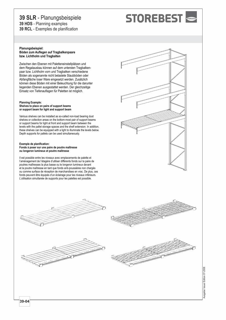
Planungsbeispiel:Böden zum Auflegen auf Tragbalkenpaarebzw. Lichtholm und Tragbalten
Zwischen den Ebenen mit Paletteneinstellplätzen unddem Regalausbau können auf dem untersten Tragbalken-paar bzw. Lichtholm vorn und Tragbalken verschiedeneBöden als sogenannte nicht belastete Staubböden oderAbfangfläche loser Ware eingesetzt werden. Zusätzlichkönnen diese Böden mit einer Beleuchtung für die darunterliegenden Ebenen ausgestattet werden. Der gleichzeitigeEinsatz von Tiefenauflagen für Paletten ist möglich.
Planning Example:Shelves to place on pairs of support beamsor support beam for light and support beam
Exemple de planification:Fonds à poser sur une paire de poutre maîtresseou longeron lumineux et poutre maîtresse
Various shelves can be installed as so-called non-load bearing dustshelves or collection areas on the bottom-most pair of support beamsor support beams for light at front and support beam between thelevels with the pallet storage spaces and the shelf extension. In addition,these shelves can be equipped with a light to illuminate the levels below.Depth supports for pallets can be used simultaneously.
Il est possible entre les niveaux avec emplacements de palette etl’aménagement de l’étagère d’utiliser différents fonds sur la paire depoutres maîtresses la plus basse ou le longeron lumineux devantet la poutre maîtresse en tant que fonds anti-poussières non chargésou comme surface de réception de marchandises en vrac. De plus, cesfonds peuvent être équipés d’un éclairage pour les niveaux inférieurs.L’utilisation simultanée de supports pour les palettes est possible.
39 SLR - Planungsbeispiele39 HDS39 RCL
- Planning examples- Exemples de planification
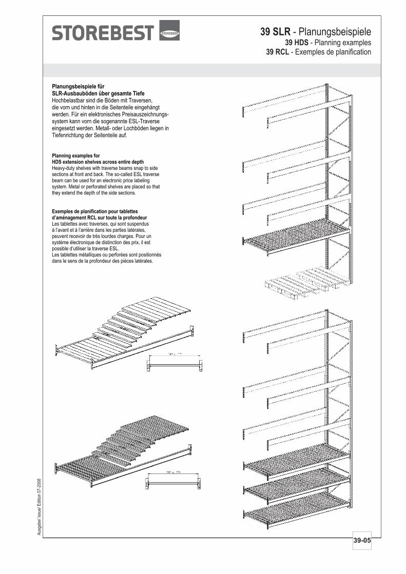
Planungsbeispiele fürSLR-Ausbauböden über gesamte TiefeHochbelastbar sind die Böden mit Traversen,die vorn und hinten in die Seitenteile eingehängtwerden. Für ein elektronisches Preisauszeichnungs-system kann vorn die sogenannte ESL-Traverseeingesetzt werden. Metall- oder Lochböden liegen inTiefenrichtung der Seitenteile auf.
Planning examples forHDS extension shelves across entire depth
Exemples de planification pour tablettesd’aménagement RCL sur toute la profondeur
Heavy-duty shelves with traverse beams snap to sidesections at front and back. The so-called ESL traversebeam can be used for an electronic price labelingsystem. Metal or perforated shelves are placed so thatthey extend the depth of the side sections.
Les tablettes avec traverses, qui sont suspendusà l’avant et à l’arrière dans les parties latérales,peuvent recevoir de très lourdes charges. Pour unsystème électronique de distinction des prix, il estpossible d’utiliser la traverse ESL.Les tablettes métalliques ou perforées sont positionnésdans le sens de la profondeur des pièces latérales.
Aus
gabe
/ Iss
ue/ E
ditio
n 07
-200
8
39-05
39 SLR - Planungsbeispiele39 HDS
39 RCL- Planning examples
- Exemples de planification
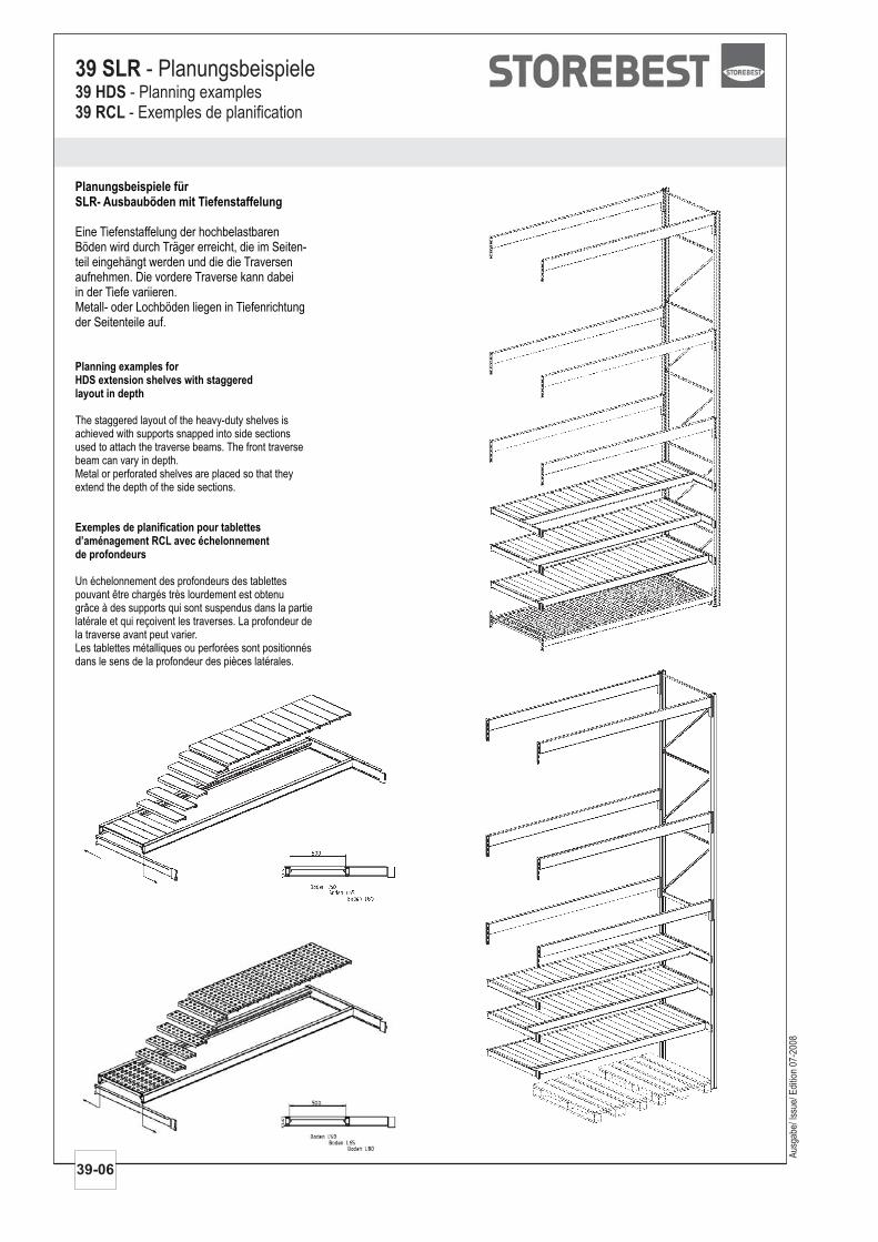
Planungsbeispiele fürSLR- Ausbauböden mit Tiefenstaffelung
Eine Tiefenstaffelung der hochbelastbarenBöden wird durch Träger erreicht, die im Seiten-teil eingehängt werden und die die Traversenaufnehmen. Die vordere Traverse kann dabeiin der Tiefe variieren.Metall- oder Lochböden liegen in Tiefenrichtungder Seitenteile auf.
Planning examples forHDS extension shelves with staggeredlayout in depth
Exemples de planification pour tablettesd’aménagement RCL avec échelonnementde profondeurs
The staggered layout of the heavy-duty shelves isachieved with supports snapped into side sectionsused to attach the traverse beams. The front traversebeam can vary in depth.Metal or perforated shelves are placed so that theyextend the depth of the side sections.
Un échelonnement des profondeurs des tablettespouvant être chargés très lourdement est obtenugrâce à des supports qui sont suspendus dans la partielatérale et qui reçoivent les traverses. La profondeur dela traverse avant peut varier.Les tablettes métalliques ou perforées sont positionnésdans le sens de la profondeur des pièces latérales.
Aus
gabe
/ Iss
ue/ E
ditio
n 07
-200
8
39-06
39 SLR - Planungsbeispiele39 HDS39 RCL
- Planning examples- Exemples de planification
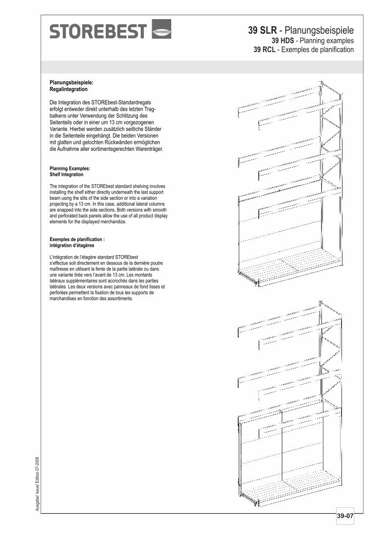
Planungsbeispiele:Regalintegration
Die Integration des STOREbest-Standardregalserfolgt entweder direkt unterhalb des letzten Trag-balkens unter Verwendung der Schlitzung desSeitenteils oder in einer um 13 cm vorgezogenenVariante. Hierbei werden zusätzlich seitliche Ständerin die Seitenteile eingehängt. Die beiden Versionenmit glatten und gelochten Rückwänden ermöglichendie Aufnahme aller sortimentsgerechten Warenträger.
Planning Examples:Shelf Integration
Exemples de planification :intégration d’étagères
The integration of the STOREbest standard shelving involvesinstalling the shelf either directly underneath the last supportbeam using the slits of the side section or into a variationprojecting by a 13 cm. In this case, additional lateral columnsare snapped into the side sections. Both versions with smoothand perforated back panels allow the use of all product displayelements for the displayed merchandize.
L’intégration de l’étagère standard STOREbests’effectue soit directement en dessous de la dernière poutremaîtresse en utilisant la fente de la partie latérale ou dansune variante tirée vers l’avant de 13 cm. Les montantslatéraux supplémentaires sont accrochés dans les partieslatérales. Les deux versions avec panneaux de fond lisses etperforées permettent la fixation de tous les supports demarchandises en fonction des assortiments.
Aus
gabe
/ Iss
ue/ E
ditio
n 07
-200
8
39-07
39 SLR - Planungsbeispiele39 HDS
39 RCL- Planning examples
- Exemples de planification
Artikel Masse cm Art.-Nr. Ausführung
Aus
gabe
/ Iss
ue/ E
ditio
n 07
-200
8
39-08
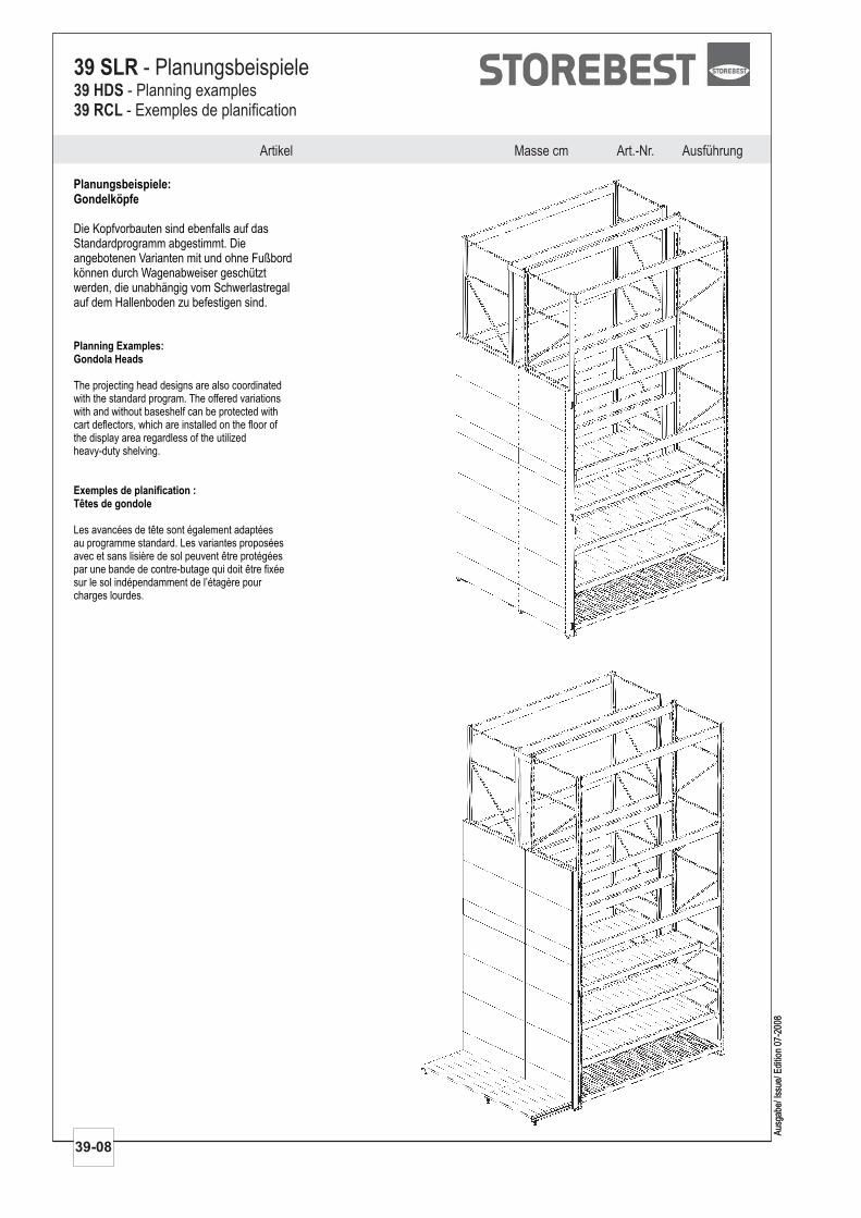
Planungsbeispiele:Gondelköpfe
Die Kopfvorbauten sind ebenfalls auf dasStandardprogramm abgestimmt. Dieangebotenen Varianten mit und ohne Fußbordkönnen durch Wagenabweiser geschütztwerden, die unabhängig vom Schwerlastregalauf dem Hallenboden zu befestigen sind.
Planning Examples:Gondola Heads
Exemples de planification :Têtes de gondole
The projecting head designs are also coordinatedwith the standard program. The offered variationswith and without baseshelf can be protected withcart deflectors, which are installed on the floor ofthe display area regardless of the utilizedheavy-duty shelving.
Les avancées de tête sont également adaptéesau programme standard. Les variantes proposéesavec et sans lisière de sol peuvent être protégéespar une bande de contre-butage qui doit être fixéesur le sol indépendamment de l’étagère pourcharges lourdes.
Aus
gabe
/ Iss
ue/ E
ditio
n 07
-200
8
39 SLR - Planungsbeispiele39 HDS39 RCL
- Planning examples- Exemples de planification
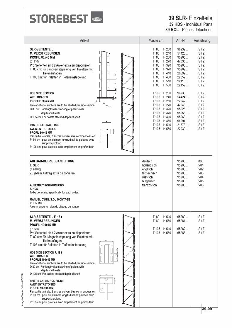
SLR-SEITENTEILM. VERSTREBUNGENPROFIL 80x45 MM
T 80 H 200 96239... S / ZT 80 H 240 54423... S / ZT 80 H 250 95905... S / ZT 80 H 270 47035... S / Z
Pro Seitenteil sind 2 Anker extra zu disponieren. T 80 H 320 95906... S / ZT 80 cm: für Längseinstapelung von Paletten mit T 80 H 370 95909... S / Z
Tiefenauflagen T 80 H 410 20599... S / ZT 105 cm: für Paletten in Tiefeneinstapelung T 80 H 460 22052… S / Z
T 80 H 510 22115… S / ZT 80 H 560 22159… S / Z
T 105 H 200 96238… S / ZT 105 H 240 54424… S / ZT 105 H 250 22042… S / ZT 105 H 270 42046… S / ZT 105 H 320 95926… S / ZT 105 H 370 95956… S / ZT 105 H 410 95963… S / ZT 105 H 460 96094… S / ZT 105 H 510 21573… S / ZT 105 H 560 22039… S / Z
(01310)
Two additional anchors are to be allotted per side section.
D 80 cm: For lengthwise stacking of pallets with
depth shelf rests
D 105 cm: For pallets stacked depth of shelf
Par partie latérale, 2 ancres doivent être commandées en plus.P 80 cm : pour empilement longitudinal de palettes avec
supports profondP 105 cm: pour palettes avec empilement en profondeur
HDS SIDE SECTION
WITH BRACES
PROFILE 80x45 MM
PARTIE LATERALE RCL
AVEC ENTRETOISES
PROFIL 80x45 MM
Masse cm Art.-Nr. AusführungArtikel
39 SLR- Einzelteile39 HDS
39 RCL- Individual Parts
- Pièces détachées
Aus
gabe
/ Iss
ue/ E
ditio
n 07
-200
8
AUFBAU-BETRIEBSANLEITUNGF. SLR
deutsch 95903... 000holländisch 95903... V01englisch 95903... V02
Zu jedem Auftrag extra disponieren. tschechisch 95903... V03russisch 95903... V04bulgarisch 95903... V05französisch 95903... V06
(F 78480)
To be generated specifically for each order.
A commander en plus de chaque demande.
ASSEMBLY INSTRUCTIONS
F. HDS
MANUEL D'UTILIS.DU MONTAGEPOUR RCL
39-09
SLR-SEITENTEIL F. 18 tM. VERSTREBUNGENPROFIL 100x45 MM
T 80 H 510 65280... S / ZT 80 H 560 65281... S / Z
T 105 H 510 65282… S / ZPro Seitenteil sind 2 Anker extra zu disponieren. T 105 H 560 65283… S / ZT 80 cm: für Längseinstapelung von Paletten mit
TiefenauflagenT 105 cm: für Paletten in Tiefeneinstapelung
(01320)
Two additional anchors are to be allotted per side section.D 80 cm: For lengthwise stacking of pallets with
depth shelf restsD 105 cm: For pallets stacked depth of shelf
Par partie latérale, 2 ancres doivent être commandées en plus.P 80 cm : pour empilement longitudinal de palettes avec
supports profondP 105 cm: pour palettes avec empilement en profondeur
HDS SIDE SECTION F. 18 tWITH BRACESPROFILE 100x45 MM
PARTIE LATER. RCL PR.18tAVEC ENTRETOISESPROFIL 100x45 MM

Aus
gabe
/ Iss
ue/ E
ditio
n 07
-200
8
Artikel Masse cm Art.-Nr. Ausführung
39-10
SCHWERLAST-ANKERDURCHMESSER 14 MM
L 10 44041... 000L 13 80028... 000L 18 80029... 000
L 10 cm: für Hallenböden B25 ohneDeckschichten.
L 13/ 18 cm: für Hallenböden B25 mitDeckschichten bis 30/ 80 mm.
Zur Befestigung des Seitenteils 2x, für denEckschutz 3x disponieren.
(35538)
L 10 cm: For display area floors B25 withoutcover layers/coatings.
L 13/ 18 cm: For display area floors B25 withcover layers/coatings up to 30/ 80 mm.
To attach side section 2x, allot 3x for thecorner protection.
HEAVY-DUTY ANCHORDIAMETER 14 MM
ANCRES CHARGES LOURDESDIAMETRE 14 MML 10 cm: pour sols de hall B25 sans
couche de surfaceL 13/ 18 cm: pour sols de hall B25 avec
couches de surface jusqu'à 30/ 80 mm.A commander pour fixer la partie latérale 2x,pour la protection des coins 3x.
LASTENVERTEILUNGSPLATTEF. SLR MIT INTEGRATIONVERZINKT
L 14 T 86 95037... 659L 14 T 111 15514... 659
Für Böden mit geringerer Tragfähigkeit.Einzusetzen, wenn unten Wagenabweiseroder Tragbalken geplant sind.
(04939)
For floors with low load bearing capacity. To be used, ifcart deflectors or support beams are allotted below.
Pour les sols de faible portée adm.A utiliser si des bandes de contre-butage inférieuresou des poutres maîtresse sont planifiés.
LOAD DISTRIBUTION PLATEFOR HDS WITH INTEGRATIONGALVANIZED
PLAQUE REPARTITION CHARGEPOUR RCL AVEC INTEGRATIONGALVANISEE
AUFSTECKERF. SLR F. 18 tPROFIL 100x45 MM
T 80 H 24 65261... S / Z
T 105 H 24 65259… S / ZT 105 H 36 53890… S / Z(02612)
EXTENSIONFOR HDS F. 18 tPROFILE 100x45 MM
REHAUSSEPOUR RCL PR. 18 tPROFIL 100x45 MM
AUFSTECKER F. SAEULEF. SLR F. 18 tPROFIL 100x45 MM
H 42 53217... S / Z
Nur zur Aufnahme dekorativer Elemente.(02614)
EXTENSION FOR COLUMNFOR HDS F. 18 tPROFILE 100x45 MM
REHAUSSE PR. COLONNEPOUR RCL PR. 18 tPROFIL 100x45 MM
39 SLR- Einzelteile39 HDS39 RCL
- Individual Parts- Pièces détachées
AusführungMasse cm Art.-Nr.Artikel
Aus
gabe
/ Iss
ue/ E
ditio
n 07
-200
8
39-11
39 SLR- Einzelteile39 HDS
39 RCL- Individual Parts
- Pièces détachées
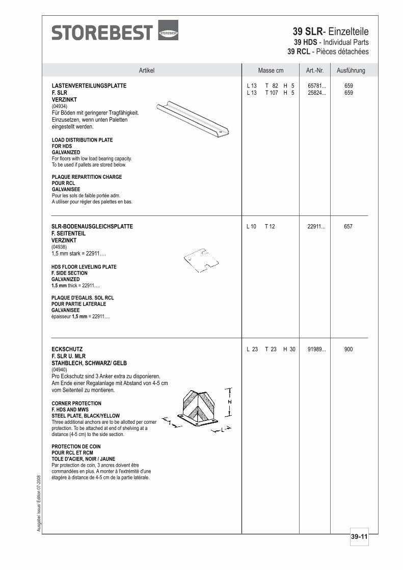
LASTENVERTEILUNGSPLATTEF. SLRVERZINKT
L 13 T 82 H 5 65781... 659L 13 T 107 H 5 25824... 659
Für Böden mit geringerer Tragfähigkeit.Einzusetzen, wenn unten Paletteneingestellt werden.
(04934)
For floors with low load bearing capacity.To be used if pallets are stored below.
Pour les sols de faible portée adm.A utiliser pour régler des palettes en bas.
LOAD DISTRIBUTION PLATEFOR HDSGALVANIZED
PLAQUE REPARTITION CHARGEPOUR RCLGALVANISEE
SLR-BODENAUSGLEICHSPLATTEF. SEITENTEILVERZINKT
L 10 T 12 22911... 657
1,5 mm stark = 22911….(04938)
thick = 22911….
épaisseur = 22911….
HDS FLOOR LEVELING PLATEF. SIDE SECTIONGALVANIZED1.5 mm
PLAQUE D'EGALIS. SOL RCLPOUR PARTIE LATERALEGALVANISEE
1,5 mm
ECKSCHUTZF. SLR U. MLRSTAHBLECH, SCHWARZ/ GELB
L 23 T 23 H 30 91989... 900
Pro Eckschutz sind 3 Anker extra zu disponieren.Am Ende einer Regalanlage mit Abstand von 4-5 cmvom Seitenteil zu montieren.
(04940)
Three additional anchors are to be allotted per cornerprotection. To be attached at end of shelving at adistance (4-5 cm) to the side section.
Par protection de coin, 3 ancres doivent êtrecommandées en plus. A monter à l'extrémité d'uneétagère à distance de 4-5 cm de la partie latérale.
CORNER PROTECTIONF. HDS AND MWSSTEEL PLATE, BLACK/YELLOW
PROTECTION DE COINPOUR RCL ET RCMTOLE D'ACIER, NOIR / JAUNE
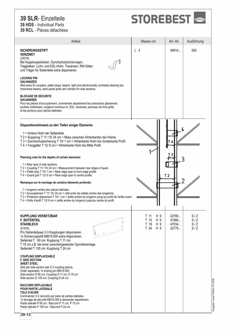
SICHERUNGSSTIFTVERZINKT
L 4 59910... 000
Bei Kupplungsstücken, Durchschubsicherungen,Tragbalken, Licht- und ESL-Holm, Traversen, RW-Gitter,und Träger für Seitenteile extra disponieren.
(35278)
Allot extra for couplers, pallet stops, beams, light and electronically controlled steering bar,transverse beams, back panel grids and carriers for side sections.
Pour les pièces d'accouplement, commander séparément les protections glissement,poutres maîtresses, longeron lumineux et ESL, traverses, panneau de fond grille,et les porteurs pour pièces latérales.
LOCKING PINGALVANIZED
BLOCAGE DE SECURITEGALVANISEE
Artikel Masse cm Art.-Nr. Ausführung
39-12
39 SLR- Einzelteile39 HDS39 RCL
- Individual Parts- Pièces détachées
T 2
T 3
T 4
Dispositionshinweis zu den Tiefen einiger Elemente:
1 = hintere Holm der SeitenteileT 2 = Kupplung T 11/ 15/ 24 cm = Mass zwischen Hinterkanten der HolmeT 3 = Durchschubsicherung T 10/ 1 cm = Hinterkante Holm bis Vorderkante ProfilT 4 = Fanggitter T 12/ 6 cm = Hinterkante Holm bis Mitte Profil
Planning note for the depths of certain elements:
Remarque sur le montage de certains éléments profonds :
1 = Rear spar of side sectionsT 2 = Coupling T 11/ 15/ 24 cm = Measurement between rear edges of sparsT 3 = Pallet stop T 10/ 1 cm = Rear edge spar to front edge profileT 4 = Guard grid T 12/ 6 cm = Rear edge spar to centre profile
1 = longeron arrière des pièces latéralesT 2 = Accouplement T 11/ 15/ 24 cm = côte entre les arêtes arrière des longeronsT 3 = Protection glissement T 10/ 1 cm = arête arrière du longeron jusqu'au profil de l'arête avantT 4 = Grille d'arrêt T 12/ 6 cm = arête arrière du longeron jusqu'au centre du profil
KUPPLUNG VERSETZBARF. SEITENTEILSTAHBLECH
T 11 H 9 22780... S / ZT 15 H 9 41990... S / ZT 18 H 9 47034... S / ZT 24 H 9 22779... S / Z
Pro Seitenteilpaar 2-3 Kupplungen disponieren.1x Sicherungsstift 68619.000 extra disponieren.Seitenteil T 80 cm: Kupplung T 11 cm,T 15 cm z.B. bei einer zwischengesetzten SprinkleranlageSeitenteil T 105 cm: Kupplung T 24 cm
(01975)
Allot per side section pair 2-3 coupling pieces.Order separately 1x locking pin 68619.000.Side section D 80 cm: Coupling D 11 cm, D 15 cmSide section D 105 cm: Coupling D 24 cm
Commander 2-3 raccords par paire de parties latérales.1x blocage de sécurité 68619.000 à demander séparément.Partie latérale P 80 cm : Raccord P 11 cm, P 15 cmPartie latérale P 105 cm : Raccord P 24 cm
COUPLING DISPLACEABLEF. SIDE SECTIONSHEET STEEL
RACCORD DEPLACABLEPOUR PARTIE LATERALETOLE D'ACIER
Aus
gabe
/ Iss
ue/ E
ditio
n 07
-200
8
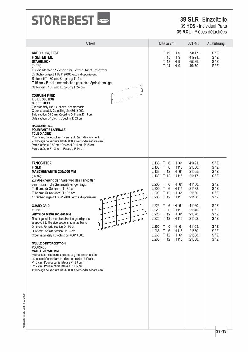
FANGGITTERF. SLRMASCHENWEITE 200x200 MM
L 133 T 6 H 61 41421... S / ZL 133 T 6 H 115 21530... S / ZL 133 T 12 H 61 21565... S / ZL 133 T 12 H 115 21417... S / Z
Zur Absicherung der Ware wird das Fanggittervon hinten in die Seitenteile eingehängt. L 200 T 6 H 61 41450... S / ZT 6 cm: für Seitenteil T 80 cm L 200 T 6 H 115 21538... S / ZT 12 cm: für Seitenteil T 105 cm L 200 T 12 H 61 21566... S / Z4x Sicherungsstift 68619.000 extra disponieren. L 200 T 12 H 115 21450... S / Z
L 225 T 6 H 61 41460... S / ZL 225 T 6 H 115 21540... S / ZL 225 T 12 H 61 21570... S / ZL 225 T 12 H 115 21502... S / Z
L 266 T 6 H 61 41463... S / ZL 266 T 6 H 115 21550... S / ZL 266 T 12 H 61 21588... S / ZL 266 T 12 H 115 21508... S / Z
(06992)
To safeguard the merchandize, the guard grid issnapped into the side sections from the back.
D 6 cm: For side section D 80 cm
D 12 cm: For side section D 105 cm
Order separately 4x locking pin 68619.000.
Pour assurer les marchandises, la grille d'interceptionest accrochée par l'arrière dans les parties latérales.P 6 cm : Pour la partie latérale P 80 cmP 12 cm : Pour la partie latérale P 105 cm4x blocage de sécurité 68619.000 à demander séparément.
GUARD GRID
F. HDS
WIDTH OF MESH 200x200 MM
GRILLE D'INTERCEPTIONPOUR RCLMAILLE 200x200 MM
AusführungMasse cm Art.-Nr.Artikel
Aus
gabe
/ Iss
ue/ E
ditio
n 07
-200
8
39-13
39 SLR- Einzelteile39 HDS
39 RCL- Individual Parts
- Pièces détachées
KUPPLUNG, FESTF. SEITENTEILSTAHBLECH
T 11 H 9 74417... S / ZT 15 H 9 41991... S / ZT 18 H 9 65239... S / ZT 24 H 9 49470... S / Z
Für die Montage 1x oben einzusetzen. Nicht umsetzbar.2x Sicherungsstift 68619.000 extra disponieren.Seitenteil T 80 cm: Kupplung T 11 cm,T 15 cm z.B. bei einer zwischen gesetzten SprinkleranlageSeitenteil T 105 cm: Kupplung T 24 cm
(01976)
For assembly use 1x above. Not moveable.Order separately 2x locking pin 68619.000.Side section D 80 cm: Coupling D 11 cm, D 15 cmSide section D 105 cm: Coupling D 24 cm
Pour le montage, utiliser 1x en haut. Sans déplacement.2x blocage de sécurité 68619.000 à demander séparément.Partie latérale P 80 cm : Raccord P 11 cm, P 15 cmPartie latérale P 105 cm : Raccord P 24 cm
COUPLING FIXEDF. SIDE SECTIONSHEET STEEL
RACCORD FIXEPOUR PARTIE LATERALETOLE D'ACIER
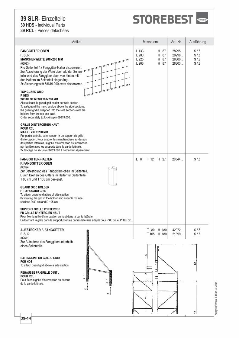
FANGGITTER OBENF. SLRMASCHENWEITE 200x200 MM
L 133 H 87 28295... S / ZL 200 H 87 28298... S / ZL 225 H 87 28300... S / ZL 266 H 87 28303... S / Z
Pro Seitenteil 1x Fanggitter-Halter disponieren.Zur Absicherung der Ware oberhalb der Seiten-teile wird das Fanggitter oben von hinten mitden Haltern im Seitenteil eingehängt.2x Sicherungsstift 68619.000 extra disponieren.
(06993)
Allot at least 1x guard grid holder per side section.To safeguard the merchandize above the side sections,the guard grid is snapped into the side sections with theholders from the top and back.Order separately 2x locking pin 68619.000.
Par partie latérale, commander 1x un support de grilled'interception. Pour assurer les marchandises au-dessusdes parties latérales, la grille d'interception est accrochéepar l'arrière avec les supports dans la partie latérale.2x blocage de sécurité 68619.000 à demander séparément.
TOP GUARD GRIDF. HDSWIDTH OF MESH 200x200 MM
GRILLE D'INTERCEP.EN HAUTPOUR RCLMAILLE 200 x 200 MM
FANGGITTER-HALTER L 8 T 12 H 27 28344... S / Z
Zur Befestigung des Fanggitters oben im Seitenteil.Durch Drehen des Gitters im Halter für SeitenteileT 80 cm und T 105 cm geeignet.
F. FANGGITTER OBEN(06994)
To attach guard grid at top of side section.By rotating the grid in the holder also suitable for sidesections D 80 cm and D 105 cm.
Pour fixer la grille d’interception en haut dans la partie latérale.En tournant la grille dans le support pour les parties latérales adapté pour P 80 cm et P 105 cm.
GUARD GRID HOLDERF. TOP GUARD GRID
SUPPORT GRILLE D’INTERCEPPR GRILLE D’INTERC.EN HAUT
AUFSTECKER F. FANGGITTERF. SLR
T 80 H 180 42072... S / ZT 105 H 180 21399... S / Z
Zur Aufnahme des Fanggitters oberhalbeines Seitenteils.
(02611)
To attach guard grid above a side section.
Pour fixer la grille d'interception au-dessusde la partie latérale.
EXTENSION FOR GUARD GRIDFOR HDS
REHAUSSE PR.GRILLE D'INT .POUR RCL
Artikel Masse cm Art.-Nr. Ausführung
39-14
39 SLR- Einzelteile39 HDS39 RCL
- Individual Parts- Pièces détachées
Aus
gabe
/ Iss
ue/ E
ditio
n 07
-200
8
AusführungMasse cm Art.-Nr.Artikel
Aus
gabe
/ Iss
ue/ E
ditio
n 07
-200
8
39-15
39 SLR- Einzelteile39 HDS
39 RCL- Individual Parts
- Pièces détachées
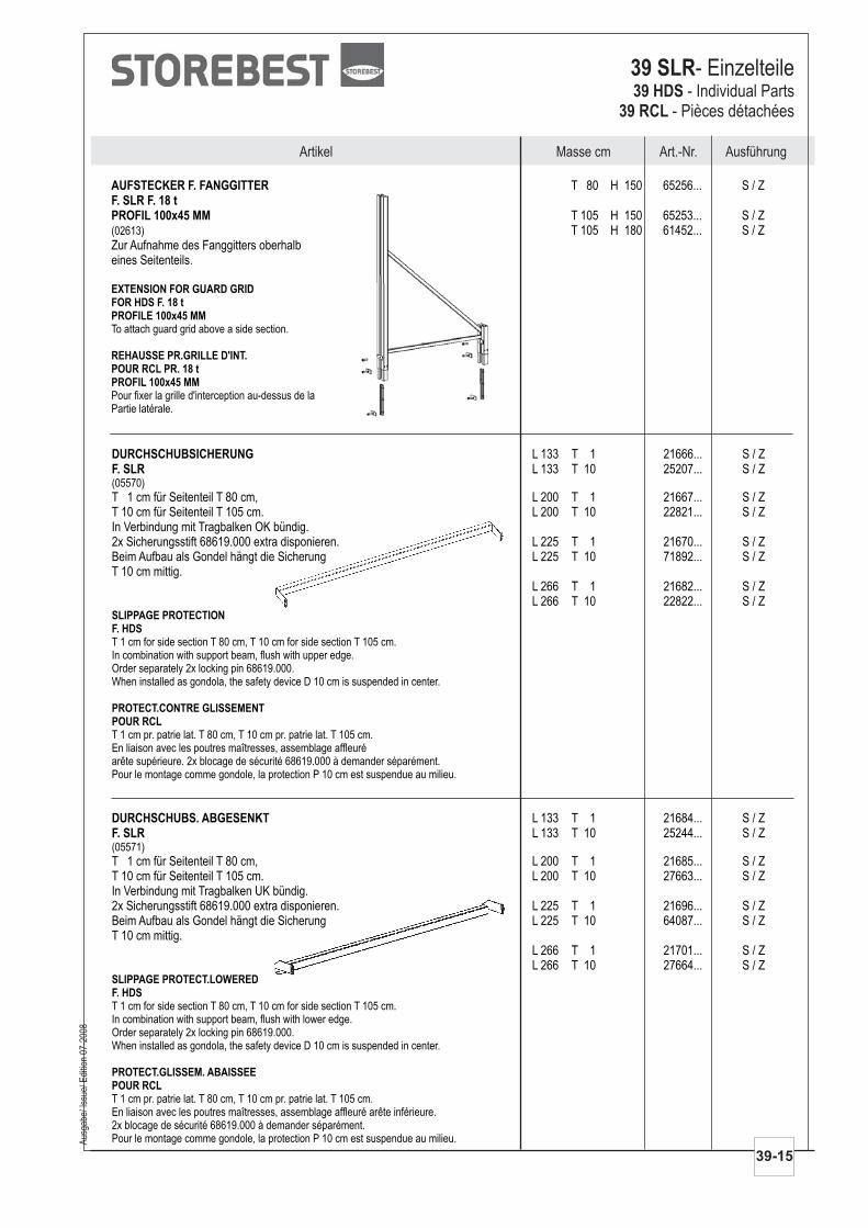
AUFSTECKER F. FANGGITTERF. SLR F. 18 tPROFIL 100x45 MM
T 80 H 150 65256... S / Z
T 105 H 150 65253... S / ZT 105 H 180 61452... S / Z
Zur Aufnahme des Fanggitters oberhalbeines Seitenteils.
(02613)
To attach guard grid above a side section.
Pour fixer la grille d'interception au-dessus de laPartie latérale.
EXTENSION FOR GUARD GRIDFOR HDS F. 18 tPROFILE 100x45 MM
REHAUSSE PR.GRILLE D'INT.POUR RCL PR. 18 tPROFIL 100x45 MM
DURCHSCHUBSICHERUNGF. SLR
L 133 T 1 21666... S / ZL 133 T 10 25207... S / Z
T 1 cm für Seitenteil T 80 cm, L 200 T 1 21667... S / ZT 10 cm für Seitenteil T 105 cm. L 200 T 10 22821... S / ZIn Verbindung mit Tragbalken OK bündig.2x Sicherungsstift 68619.000 extra disponieren. L 225 T 1 21670... S / ZBeim Aufbau als Gondel hängt die Sicherung L 225 T 10 71892... S / ZT 10 cm mittig.
L 266 T 1 21682... S / Z
(05570)
T 1 cm for side section T 80 cm, T 10 cm for side section T 105 cm.In combination with support beam, flush with upper edge.Order separately 2x locking pin 68619.000.When installed as gondola, the safety device D 10 cm is suspended in center.
T 1 cm pr. patrie lat. T 80 cm, T 10 cm pr. patrie lat. T 105 cm.En liaison avec les poutres maîtresses, assemblage affleuréarête supérieure. 2x blocage de sécurité 68619.000 à demander séparément.Pour le montage comme gondole, la protection P 10 cm est suspendue au milieu.
SLIPPAGE PROTECTIONF. HDS
PROTECT.CONTRE GLISSEMENTPOUR RCL
L 266 T 10 22822... S / Z
DURCHSCHUBS. ABGESENKTF. SLR
L 133 T 1 21684... S / ZL 133 T 10 25244... S / Z
T 1 cm für Seitenteil T 80 cm, L 200 T 1 21685... S / ZT 10 cm für Seitenteil T 105 cm. L 200 T 10 27663... S / ZIn Verbindung mit Tragbalken UK bündig.2x Sicherungsstift 68619.000 extra disponieren. L 225 T 1 21696... S / ZBeim Aufbau als Gondel hängt die Sicherung L 225 T 10 64087... S / ZT 10 cm mittig.
L 266 T 1 21701... S / ZL 266 T 10 27664... S / Z
(05571)
T 1 cm for side section T 80 cm, T 10 cm for side section T 105 cm.In combination with support beam, flush with lower edge.Order separately 2x locking pin 68619.000.When installed as gondola, the safety device D 10 cm is suspended in center.
T 1 cm pr. patrie lat. T 80 cm, T 10 cm pr. patrie lat. T 105 cm.En liaison avec les poutres maîtresses, assemblage affleuré arête inférieure.2x blocage de sécurité 68619.000 à demander séparément.Pour le montage comme gondole, la protection P 10 cm est suspendue au milieu.
SLIPPAGE PROTECT.LOWEREDF. HDS
PROTECT.GLISSEM. ABAISSEEPOUR RCL
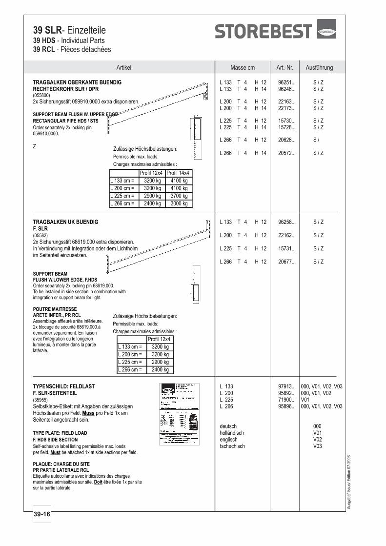
TRAGBALKEN UK BUENDIGF. SLR
L 133 T 4 H 12 96258... S / Z
L 200 T 4 H 12 22162... S / Z2x Sicherungsstift 68619.000 extra disponieren.In Verbindung mit Integration oder dem Lichtholm L 225 T 4 H 12 15731... S / Zim Seitenteil einzusetzen.
L 266 T 4 H 12 20677... S / Z
(05582)
Order separately 2x locking pin 68619.000.To be installed in side section in combination withintegration or support beam for light.
Assemblage affleuré arête inférieure.2x blocage de sécurité 68619.000.àdemander séparément. En liaisonavec l'intégration ou le longeronlumineux, à monter dans la partielatérale.
SUPPORT BEAMFLUSH W.LOWER EDGE, F.HDS
POUTRE MAITRESSEARETE INFER., PR RCL Zulässige Höchstbelastungen:
Permissible max. loads:
Charges maximales admissibles :
Profil 12x4
L 133 cm = 3200 kg
L 200 cm = 3200 kg
L 225 cm = 2900 kg
L 266 cm = 2400 kg
TYPENSCHILD: FELDLASTF. SLR-SEITENTEIL
L 133 97913... 000, V01, V02, V03L 200 95892... 000, V01, V02L 225 71900... V01
Selbstklebe-Etikett mit Angaben der zulässigen L 266 95896... 000, V01, V02, V03Höchstlasten pro Feld. pro Feld 1x amSeitenteil angebracht sein.
deutsch 000holländisch V01englisch V02tschechisch V03
(35955)
Self-adhesive label listing permissible max. loadsper field. be attached 1x at side sections per field.
Etiquette autocollante avec indications des chargesmaximales admissibles sur site. être fixée 1x par sitesur la partie latérale.
Muss
TYPE PLATE: FIELD LOAD
F. HDS SIDE SECTION
PLAQUE: CHARGE DU SITEPR PARTIE LATERALE RCL
Must
Doit
Zulässige Höchstbelastungen:
Permissible max. loads:
Charges maximales admissibles :
Profil 12x4 Profil 14x4
L 133 cm = 3200 kg 4100 kg
L 200 cm = 3200 kg 4100 kg
L 225 cm = 2900 kg 3700 kg
L 266 cm = 2400 kg 3000 kg
Artikel Masse cm Art.-Nr. Ausführung
39-16
39 SLR- Einzelteile39 HDS39 RCL
- Individual Parts- Pièces détachées
TRAGBALKEN OBERKANTE BUENDIGRECHTECKROHR SLR / DPR
L 133 T 4 H 12 96251... S / ZL 133 T 4 H 14 96246... S / Z
2x Sicherungsstift 059910.0000 extra disponieren. L 200 T 4 H 12 22163... S / ZL 200 T 4 H 14 22173... S / Z
L 225 T 4 H 12 15730... S / ZL 225 T 4 H 14 15728... S / Z
L 266 T 4 H 12 20628... S /Z
L 266 T 4 H 14 20572... S / Z
(055800)
Order separately 2x locking pin059910.0000.
SUPPORT BEAM FLUSH W. UPPER EDGE
RECTANGULAR PIPE HDS / STS
Aus
gabe
/ Iss
ue/ E
ditio
n 07
-200
8
AusführungMasse cm Art.-Nr.Artikel
Aus
gabe
/ Iss
ue/ E
ditio
n 07
-200
8
39-17
39 SLR- Einzelteile39 HDS
39 RCL- Individual Parts
- Pièces détachées
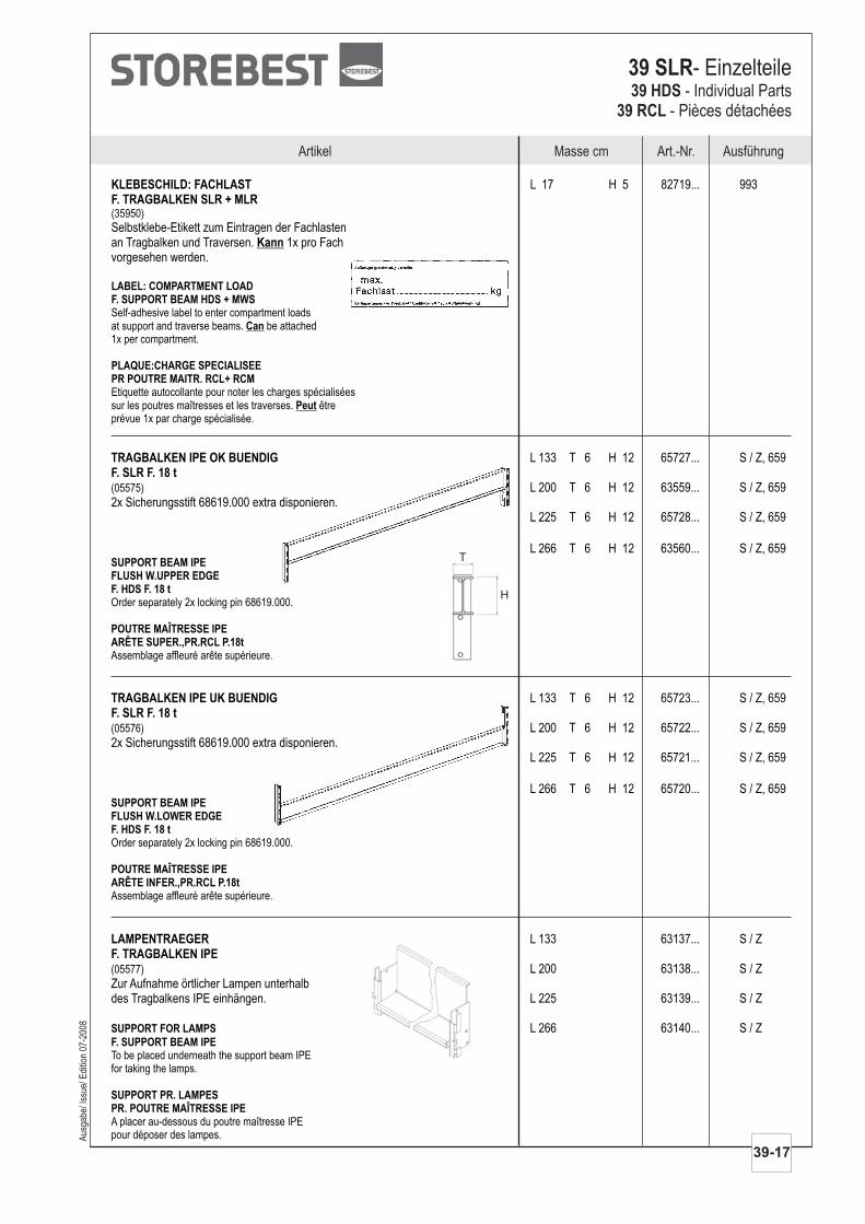
KLEBESCHILD: FACHLASTF. TRAGBALKEN SLR + MLR
L 17 H 5 82719... 993
Selbstklebe-Etikett zum Eintragen der Fachlastenan Tragbalken und Traversen. 1x pro Fachvorgesehen werden.
(35950)
Self-adhesive label to enter compartment loadsat support and traverse beams. be attached1x per compartment.
Etiquette autocollante pour noter les charges spécialiséessur les poutres maîtresses et les traverses. êtreprévue 1x par charge spécialisée.
Kann
LABEL: COMPARTMENT LOADF. SUPPORT BEAM HDS + MWS
PLAQUE:CHARGE SPECIALISEEPR POUTRE MAITR. RCL+ RCM
Can
Peut
TRAGBALKEN IPE OK BUENDIGF. SLR F. 18 t
L 133 T 6 H 12 65727... S / Z, 659
L 200 T 6 H 12 63559... S / Z, 6592x Sicherungsstift 68619.000 extra disponieren.
L 225 T 6 H 12 65728... S / Z, 659
(05575)
Order separately 2x locking pin 68619.000.
Assemblage affleuré arête supérieure.
L 266 T 6 H 12 63560... S / Z, 659SUPPORT BEAM IPEFLUSH W.UPPER EDGEF. HDS F. 18 t
POUTRE MAÎTRESSE IPEARÊTE SUPER.,PR.RCL P.18t
TRAGBALKEN IPE UK BUENDIGF. SLR F. 18 t
L 133 T 6 H 12 65723... S / Z, 659
L 200 T 6 H 12 65722... S / Z, 6592x Sicherungsstift 68619.000 extra disponieren.
L 225 T 6 H 12 65721... S / Z, 659
(05576)
Order separately 2x locking pin 68619.000.
Assemblage affleuré arête supérieure.
L 266 T 6 H 12 65720... S / Z, 659SUPPORT BEAM IPEFLUSH W.LOWER EDGEF. HDS F. 18 t
POUTRE MAÎTRESSE IPEARÊTE INFER.,PR.RCL P.18t
T
H
LAMPENTRAEGERF. TRAGBALKEN IPE
L 133 63137... S / Z
L 200 63138... S / ZZur Aufnahme örtlicher Lampen unterhalbdes Tragbalkens IPE einhängen. L 225 63139... S / Z
(05577)
To be placed underneath the support beam IPEfor taking the lamps.
A placer au-dessous du poutre maîtresse IPEpour déposer des lampes.
SUPPORT FOR LAMPS
F. SUPPORT BEAM IPE
SUPPORT PR. LAMPESPR. POUTRE MAÎTRESSE IPE
L 266 63140... S / Z

TIEFENAUFLAGEF. TRAGBALKEN, SLR
T 78 22819... S / ZT 80 21280… S / ZT 103 25271… S / Z
Zur Abstützung von eingestellten Paletten. T 105 25270… S / ZT 78 / 103 cm: beim Lichtholm und TragbalkenUK bündig. 3x pro Palette vorsehen.
(15966)
Used as support for stored pallets.D 78/ 103 cm: Flush with lower edge with supportbeam for light and support beam. Order 3x per pallet.
Pour étayer les palettes ajustées.P 78/ 103 cm : pour le longeron lumineuxet la poutre maîtresse arête inférieure. A commander 3x par palette.
DEPTH SUPPORTF. SUPPORT BEAM, HDS
SUPPORT PROFONDPR POUTRE MAITRESSE, RCL
FLUEGELSCHRAUBE M 8x12DIN 316
L 1 52596... 657
(35540)
WING SCREWDIN 316
VIS A AILETTESDIN 316
TIEFENAUFLAGE M. GEWINDEF. TRAGBALKEN, SLR
T 78 36073... S / ZT 80 36065… S / Z
Mit der Flügelschraube 52596.657 amTragbalken festsetzen. 3x pro Palette vorsehen.
(15976)
To be fastened to the support beam with thewing screw 52596.657. Order 3x per pallet.
A fixer à la poutre maîtresse avec lavis à ailettes 52596.657. A commander 3x par palette.
DEPTH SUPPORT WITH TREADFOR SUPPORT BEAM, HDS
SUPPORT PROFOND, FILETAGEPR POUTRE MAITRESSE, RCL
TIEFENAUFLAGE EINLEGEBOD.F. TRAGBALKEN SLRSTAHLBLECH
T 78 32596... S / ZT 80 20810... S / ZT 103 32595... S / ZT 105 20813... S / Z
Zur Aufnahme eines Einlegebodens.T 78 / 103 cm: beim Lichtholm und TragbalkenUK bündig.
(15959)
For accommodating a shelf for insertion.D 78/ 103 cm: Flush with lower edge with supportbeam for light and support beam.
Pour le soutien d'une tablette.P 78/ 103 cm : pour le longeron lumineuxet la poutre maîtresse arête inférieure.
DEPTH SUP. SHELF F.INSERTF. SUPPORT BEAM HDSSHEET STEEL
SUPPORT TRANSV.P.TABLETTEPR POUTRE MAITRESSE RCLTOLE D'ACIER
Artikel Masse cm Art.-Nr. Ausführung
39-18
39 SLR- Einzelteile39 HDS39 RCL
- Individual Parts- Pièces détachées
Aus
gabe
/ Iss
ue/ E
ditio
n 07
-200
8
AusführungMasse cm Art.-Nr.Artikel
Aus
gabe
/ Iss
ue/ E
ditio
n 07
-200
8
39-19
39 SLR- Einzelteile39 HDS
39 RCL- Individual Parts
- Pièces détachées
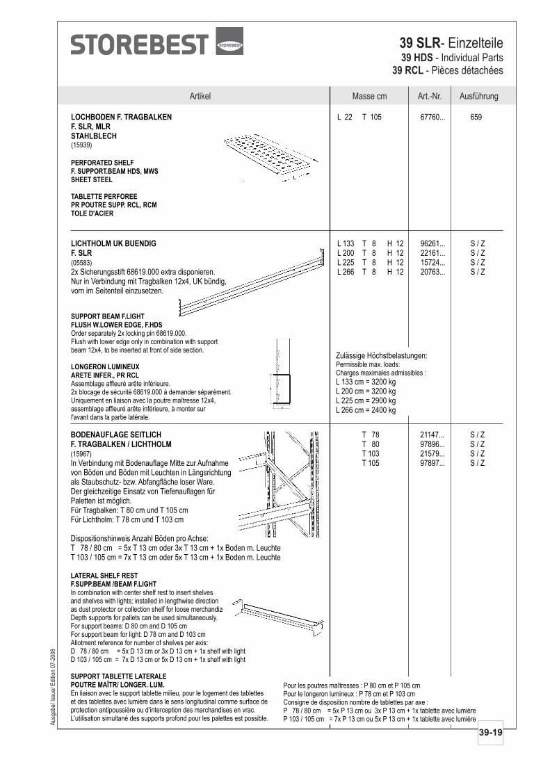
BODENAUFLAGE SEITLICHF. TRAGBALKEN / LICHTHOLM
T 78 21147... S / ZT 80 97896... S / ZT 103 21579... S / Z
In Verbindung mit Bodenauflage Mitte zur Aufnahme T 105 97897... S / Zvon Böden und Böden mit Leuchten in Längsrichtungals Staubschutz- bzw. Abfangfläche loser Ware.Der gleichzeitige Einsatz von Tiefenauflagen fürPaletten ist möglich.Für Tragbalken: T 80 cm und T 105 cmFür Lichtholm: T 78 cm und T 103 cm
Dispositionshinweis Anzahl Böden pro Achse:T 78 / 80 cm = 5x T 13 cm oder 3x T 13 cm + 1x Boden m. LeuchteT 103 / 105 cm = 7x T 13 cm oder 5x T 13 cm + 1x Boden m. Leuchte
(15967)
In combination with center shelf rest to insert shelvesand shelves with lights; installed in lengthwise directionas dust protector or collection shelf for loose merchandize.Depth supports for pallets can be used simultaneously.For support beams: D 80 cm and D 105 cmFor support beam for light: D 78 cm and D 103 cmAllotment reference for number of shelves per axis:D 78 / 80 cm = 5x D 13 cm or 3x D 13 cm + 1x shelf with lightD 103 / 105 cm = 7x D 13 cm or 5x D 13 cm + 1x shelf with light
En liaison avec le support tablette milieu, pour le logement des tabletteset des tablettes avec lumière dans le sens longitudinal comme surface deprotection antipoussière ou d’interception des marchandises en vrac.L’utilisation simultané des supports profond pour les palettes est possible.
LATERAL SHELF RESTF.SUPP.BEAM /BEAM F.LIGHT
SUPPORT TABLETTE LATERALEPOUTRE MAÎTR/ LONGER. LUM.
Zulässige Höchstbelastungen:
L 133 cm = 3200 kgL 200 cm = 3200 kgL 225 cm = 2900 kgL 266 cm = 2400 kg
Permissible max. loads:Charges maximales admissibles :
LICHTHOLM UK BUENDIGF. SLR
L 133 T 8 H 12 96261... S / ZL 200 T 8 H 12 22161... S / ZL 225 T 8 H 12 15724... S / Z
2x Sicherungsstift 68619.000 extra disponieren. L 266 T 8 H 12 20763... S / ZNur in Verbindung mit Tragbalken 12x4, UK bündig,vorn im Seitenteil einzusetzen.
(05583)
Order separately 2x locking pin 68619.000.Flush with lower edge only in combination with supportbeam 12x4, to be inserted at front of side section.
Assemblage affleuré arête inférieure.2x blocage de sécurité 68619.000 à demander séparément.Uniquement en liaison avec la poutre maîtresse 12x4,assemblage affleuré arête inférieure, à monter surl'avant dans la partie latérale.
SUPPORT BEAM F.LIGHTFLUSH W.LOWER EDGE, F.HDS
LONGERON LUMINEUXARETE INFER., PR RCL
Pour les poutres maîtresses : P 80 cm et P 105 cmPour le longeron lumineux : P 78 cm et P 103 cmConsigne de disposition nombre de tablettes par axe :P 78 / 80 cm = 5x P 13 cm ou 3x P 13 cm + 1x tablette avec lumièreP 103 / 105 cm = 7x P 13 cm ou 5x P 13 cm + 1x tablette avec lumière
LOCHBODEN F. TRAGBALKENF. SLR, MLRSTAHLBLECH
L 22 T 105 67760... 659
(15939)
PERFORATED SHELFF. SUPPORT.BEAM HDS, MWSSHEET STEEL
TABLETTE PERFOREEPR POUTRE SUPP. RCL, RCMTOLE D'ACIER

Artikel Masse cm Art.-Nr. Ausführung
39-20
39 SLR- Einzelteile39 HDS39 RCL
- Individual Parts- Pièces détachées
METALLBODENEINSEITIG U-PROFILSTAHLBLECH
L 100 T 10 49445... S / ZL 100 T 13 10530... S / Z
L 125 T 10 49494... S / ZL 125 T 13 46633... S / Z
L 133 T 10 49961... S / ZL 133 T 13 49962... S / Z
(15201)
METAL SHELF
ONE-SIDED U PROFILE
SHEET STEEL
TABLETTE METALLIQUEPROFIL U SUR UN COTETOLE D'ACIER
LOCHBODENEINSEITIG U-PROFILSTAHLBLECH
L 100 T 10 22008... S / ZL 100 T 13 22036... S / Z
L 125 T 10 22005... S / ZL 125 T 13 22007... S / Z
L 133 T 10 21979... S / ZL 133 T 13 22003... S / Z
(15969)
PERFORATED SHELF
ONE-SIDED U PROFILE
SHEET STEEL
TABLETTE PERFOREEPROFIL U SUR UN COTETOLE D'ACIER
METALLB. F. FLACHLEUCHTENEINSEITIG U-PROFILSTAHLBLECH
L 100 T 26 24304... S / ZL 125 T 26 24303... S / ZL 133 T 26 24301... S / Z
Flachleuchte, Leuchtstofflampe undVerbindungsleitung extra disponieren.
(12052)
Order flat lamp, fluorescent tube and connectinglead separately.
Lampe plate, tube fluo et cordon de raccordementà commander séparément.
METAL SHELF F. FLAT LAMPSONE-SIDED U-PROFILESHEET STEEL
TAB MET. PR.LAMPES PLATESPROFIL U UNILATERALTOLE D'ACIER
BODENAUFLAGE MITTEF. TRAGBALKEN / LICHTHOLM
T 78 21146... S / ZT 80 97905... S / ZT 103 21578... S / Z
In Verbindung mit Bodenauflage seitlich zur Aufnahme T 105 97903... S / Zvon Böden und Böden mit Leuchten in Längsrichtungals Staubschutz- bzw. Abfangfläche loser Ware.Für Tragbalken: T 80 cm und T 105 cmFür Lichtholm: T 78 cm und T 103 cm
(15968)
In combination with lateral shelf rest to insert shelves andshelves with lights in lengthwise direction; used as dust protectoror collection shelf for loose merchandize.For support beams: D 80 cm and D 105 cmFor connecting strip light element: D 78 cm and D 103 cm
En liaison avec le support tablette lateral, pour le logement des tabletteset des tablettes avec lumière dans le sens longitudinal comme surface deProtection antipoussière ou d’interception des marchandises en vrac.
CENTER SHELF RESTF.SUPP.BEAM/BEAM F.LIGHT
SUPPORT TABLETTE MILIEUPOUTRE MAITR/ LONGER.LUM.
Boden für Flachl.,Stecker hinten für Flachl.,Stecker hinten, EVG
Shelf for flat lamp, rear connector for flat lamp, rear connector, ECG
Tablette pr lampe plate, connect.arriere pr lampe plate, connect.arriere, Ballast el.
L 100 cm L 93 cm, 30 W : 62643.000 L 93 cm, 30 W : 62654.000
L 125 cm L 123 cm, 36 W : 62642.000 L 123 cm, 36 W : 62650.000
L 133 cm L 123 cm, 36 W : 62642.000 L 123 cm, 36 W : 62650.000
Aus
gabe
/ Iss
ue/ E
ditio
n 07
-200
8
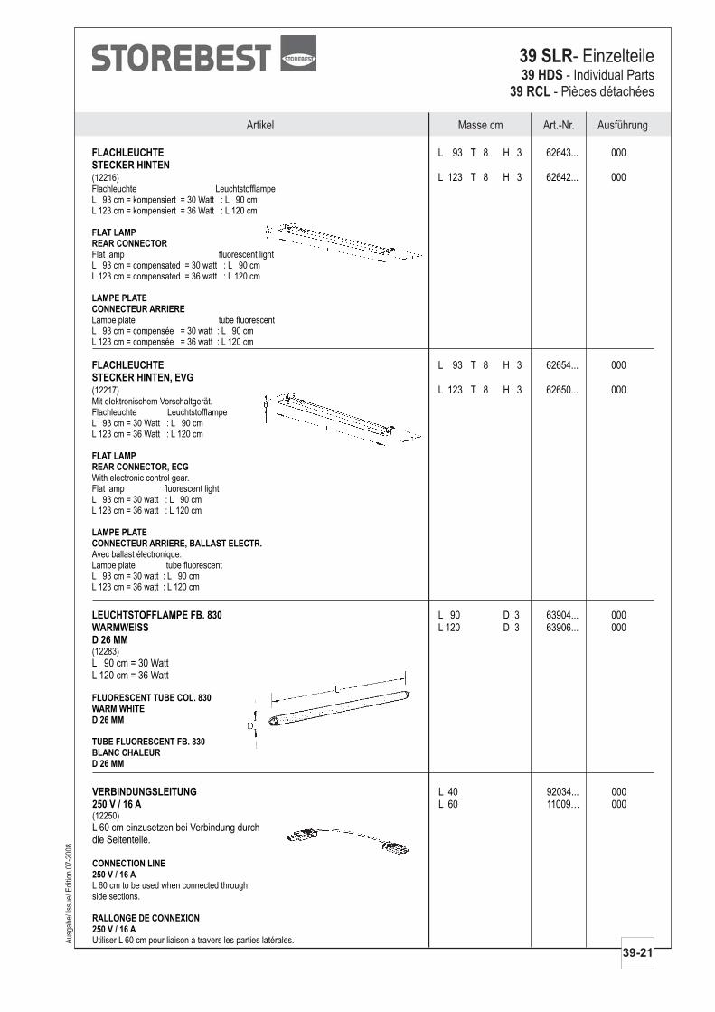
FLACHLEUCHTESTECKER HINTEN
L 93 T 8 H 3 62643... 000
L 123 T 8 H 3 62642... 000(12216)Flachleuchte LeuchtstofflampeL 93 cm = kompensiert = 30 Watt : L 90 cmL 123 cm = kompensiert = 36 Watt : L 120 cm
Flat lamp fluorescent lightL 93 cm = compensated = 30 watt : L 90 cmL 123 cm = compensated = 36 watt : L 120 cm
Lampe plate tube fluorescentL 93 cm = compensée = 30 watt : L 90 cmL 123 cm = compensée = 36 watt : L 120 cm
FLAT LAMPREAR CONNECTOR
LAMPE PLATECONNECTEUR ARRIERE
AusführungMasse cm Art.-Nr.Artikel
Aus
gabe
/ Iss
ue/ E
ditio
n 07
-200
8
39-21
39 SLR- Einzelteile39 HDS
39 RCL- Individual Parts
- Pièces détachées
FLACHLEUCHTESTECKER HINTEN, EVG
L 93 T 8 H 3 62654... 000
L 123 T 8 H 3 62650... 000(12217)Mit elektronischem Vorschaltgerät.Flachleuchte LeuchtstofflampeL 93 cm = 30 Watt : L 90 cmL 123 cm = 36 Watt : L 120 cm
With electronic control gear.Flat lamp fluorescent lightL 93 cm = 30 watt : L 90 cmL 123 cm = 36 watt : L 120 cm
Avec ballast électronique.Lampe plate tube fluorescentL 93 cm = 30 watt : L 90 cmL 123 cm = 36 watt : L 120 cm
FLAT LAMPREAR CONNECTOR, ECG
LAMPE PLATECONNECTEUR ARRIERE, BALLAST ELECTR.
LEUCHTSTOFFLAMPE FB. 830WARMWEISSD 26 MM
L 90 D 3 63904... 000L 120 D 3 63906... 000
L 90 cm = 30 WattL 120 cm = 36 Watt
(12283)
FLUORESCENT TUBE COL. 830WARM WHITED 26 MM
TUBE FLUORESCENT FB. 830BLANC CHALEURD 26 MM
VERBINDUNGSLEITUNG250 V / 16 A
L 40 92034... 000L 60 11009… 000
L 60 cm einzusetzen bei Verbindung durchdie Seitenteile.
(12250)
L 60 cm to be used when connected throughside sections.
Utiliser L 60 cm pour liaison à travers les parties latérales.
CONNECTION LINE250 V / 16 A
RALLONGE DE CONNEXION250 V / 16 A
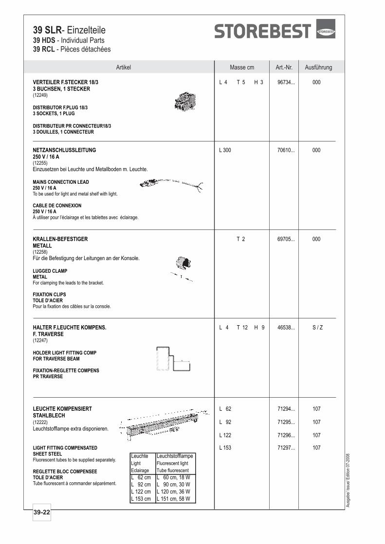
VERTEILER F.STECKER 18/33 BUCHSEN, 1 STECKER
L 4 T 5 H 3 96734... 000
(12249)
DISTRIBUTOR F.PLUG 18/33 SOCKETS, 1 PLUG
DISTRIBUTEUR PR CONNECTEUR18/33 DOUILLES, 1 CONNECTEUR
Artikel Masse cm Art.-Nr. Ausführung
39-22
39 SLR- Einzelteile39 HDS39 RCL
- Individual Parts- Pièces détachées
NETZANSCHLUSSLEITUNG250 V / 16 A
L 300 70610... 000
Einzusetzen bei Leuchte und Metallboden m. Leuchte.(12255)
To be used for light and metal shelf with light.
À utiliser pour l’éclairage et les tablettes avec éclairage.
MAINS CONNECTION LEAD250 V / 16 A
CABLE DE CONNEXION250 V / 16 A
KRALLEN-BEFESTIGERMETALL
T 2 69705... 000
Für die Befestigung der Leitungen an der Konsole.(12258)
For clamping the leads to the bracket.
Pour la fixation des câbles sur la console.
LUGGED CLAMPMETAL
FIXATION CLIPSTOLE D’ACIER
HALTER F.LEUCHTE KOMPENS.F. TRAVERSE
L 4 T 12 H 9 46538... S / Z
(12247)
HOLDER LIGHT FITTING COMPFOR TRAVERSE BEAM
FIXATION-REGLETTE COMPENSPR TRAVERSE
Aus
gabe
/ Iss
ue/ E
ditio
n 07
-200
8
LEUCHTE KOMPENSIERTSTAHLBLECH
L 62 71294... 107
L 92 71295... 107Leuchtstofflampe extra disponieren.
L 122 71296... 107
L 153 71297... 107
(12222)
Fluorescent tubes to be supplied separately.
Tube fluorescent à commander séparément.
LIGHT FITTING COMPENSATED
SHEET STEEL
REGLETTE BLOC COMPENSEETOLE D’ACIER
Leuchte Leuchtstofflampe
Light Fluorescent light
Eclairage Tube fluorescent
L 62 cm L 60 cm, 18 W
L 92 cm L 90 cm, 30 W
L 122 cm L 120 cm, 36 W
L 153 cm L 151 cm, 58 W
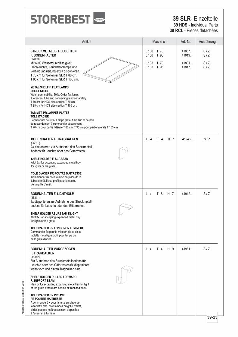
STRECKMETALLB. F.LEUCHTENF. BODENHALTER
L 100 T 70 41857... S / ZL 100 T 95 41819... S / Z
Mit 60% Wasserdurchlässigkeit. L 133 T 70 41831... S / ZFlachleuchte, Leuchtstofflampe und L 133 T 95 41817... S / ZVerbindungsleitung extra disponieren.T 70 cm für Seitenteil SLR T 80 cm,T 95 cm für Seitenteil SLR T 105 cm.
(12053)
Water permeability: 60%. Order flat lamp,fluorescent tube and connecting lead separately.T 70 cm for HDS side section T 80 cm,T 95 cm for HDS side section T 105 cm.
Perméabilité de 60%. Lampe plate, tube fluo et cordonde raccordement à commander séparément.T 70 cm pour partie latérale T 80 cm, T 95 cm pour partie latérale T 105 cm.
METAL SHELF F. FLAT LAMPSSHEET STEEL
TAB MET. PR.LAMPES PLATESTOLE D'ACIER
AusführungMasse cm Art.-Nr.Artikel
Aus
gabe
/ Iss
ue/ E
ditio
n 07
-200
8
39-23
39 SLR- Einzelteile39 HDS
39 RCL- Individual Parts
- Pièces détachées
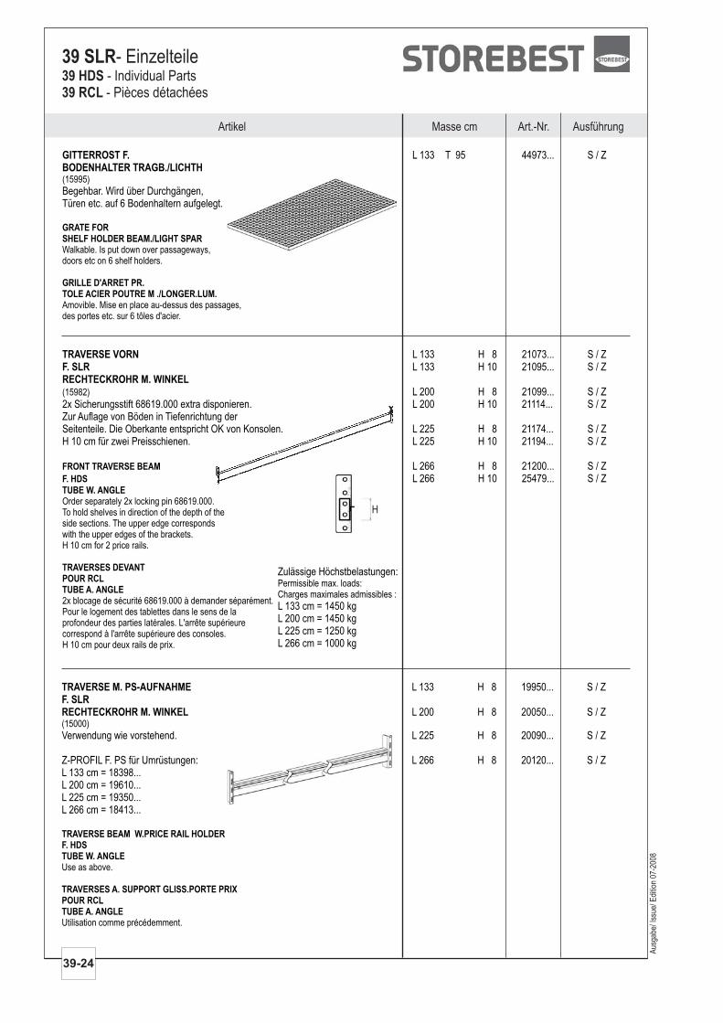
BODENHALTER F. TRAGBALKEN L 4 T 4 H 7 41946... S / Z
3x disponieren zur Aufnahme des Streckmetall-bodens für Leuchte oder des Gitterrostes.
(35310)
Allot 3x for accepting expanded metal trayfor lights or the grate.
Commander 3x pour la mise en place de latablette métallique profil pour lampe oude la grille d'arrêt.
SHELF HOLDER F. SUP.BEAM
TOLE D'ACIER PR POUTRE MAITRESSE
BODENHALTER F. LICHTHOLM L 4 T 8 H 7 41912... S / Z
3x disponieren zur Aufnahme des Streckmetall-bodens für Leuchte oder des Gitterrostes.
(35311)
Allot 3x for accepting expanded metal trayfor lights or the grate.
Commander 3x pour la mise en place de latablette métallique profil pour lampe oude la grille d'arrêt.
SHELF HOLDER F.SUP.BEAM F.LIGHT
TOLE D'ACIER PR LONGERON LUMINEUX
BODENHALTER VORGEZOGENF. TRAGBALKEN
L 4 T 4 H 9 41981... S / Z
Zur Aufnahme des Streckmetallbodens fürLeuchte oder des Gitterrostes 6x disponieren,wenn vorn und hinten Tragbalken sind.
(35312)
Plan 6x for accepting expanded metal tray for lightor the grate if there are beams at front and back.
…
A commande 6 x pour la mise en place dela tablette mét. pour lampes ou grille d'arrêt,si des poutres maîtresses sont disposéesà l'avant et à l'arrière.
SHELF HOLDER PULLED FORWARDF. SUPPORT BEAM
TOLE D'ACIER EN PREAVISPR POUTRE MAITRESSE
Artikel Masse cm Art.-Nr. Ausführung
39-24
39 SLR- Einzelteile39 HDS39 RCL
- Individual Parts- Pièces détachées
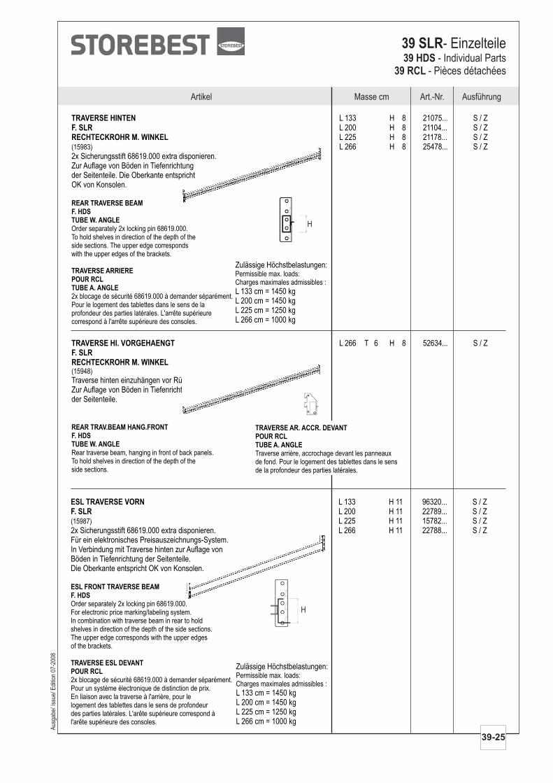
TRAVERSE VORNF. SLRRECHTECKROHR M. WINKEL
L 133 H 8 21073... S / ZL 133 H 10 21095... S / Z
L 200 H 8 21099... S / Z2x Sicherungsstift 68619.000 extra disponieren. L 200 H 10 21114... S / ZZur Auflage von Böden in Tiefenrichtung derSeitenteile. Die Oberkante entspricht OK von Konsolen. L 225 H 8 21174... S / ZH 10 cm für zwei Preisschienen. L 225 H 10 21194... S / Z
L 266 H 8 21200... S / ZL 266 H 10 25479... S / Z
(15982)
Order separately 2x locking pin 68619.000.To hold shelves in direction of the depth of theside sections. The upper edge correspondswith the upper edges of the brackets.H 10 cm for 2 price rails.
2x blocage de sécurité 68619.000 à demander séparément.Pour le logement des tablettes dans le sens de laprofondeur des parties latérales. L'arrête supérieurecorrespond à l'arrête supérieure des consoles.H 10 cm pour deux rails de prix.
FRONT TRAVERSE BEAM
F. HDS
TUBE W. ANGLE
TRAVERSES DEVANTPOUR RCLTUBE A. ANGLE
Zulässige Höchstbelastungen:
L 133 cm = 1450 kgL 200 cm = 1450 kgL 225 cm = 1250 kgL 266 cm = 1000 kg
Permissible max. loads:Charges maximales admissibles :
H
Aus
gabe
/ Iss
ue/ E
ditio
n 07
-200
8
GITTERROST F.BODENHALTER TRAGB./LICHTH
L 133 T 95 44973... S / Z
Begehbar. Wird über Durchgängen,Türen etc. auf 6 Bodenhaltern aufgelegt.
(15995)
Walkable. Is put down over passageways,doors etc on 6 shelf holders.
Amovible. Mise en place au-dessus des passages,des portes etc. sur 6 tôles d'acier.
GRATE FORSHELF HOLDER BEAM./LIGHT SPAR
GRILLE D'ARRET PR.TOLE ACIER POUTRE M ./LONGER.LUM.
TRAVERSE M. PS-AUFNAHMEF. SLRRECHTECKROHR M. WINKEL
L 133 H 8 19950... S / Z
Verwendung wie vorstehend.
Z-PROFIL F. PS für Umrüstungen:L 133 cm = 18398...L 200 cm = 19610...L 225 cm = 19350...L 266 cm = 18413...
L 200 H 8 20050... S / Z
L 225 H 8 20090... S / Z
L 266 H 8 20120... S / Z
(15000)
Use as above.
Utilisation comme précédemment.
TRAVERSE BEAM W.PRICE RAIL HOLDERF. HDSTUBE W. ANGLE
TRAVERSES A. SUPPORT GLISS.PORTE PRIXPOUR RCLTUBE A. ANGLE
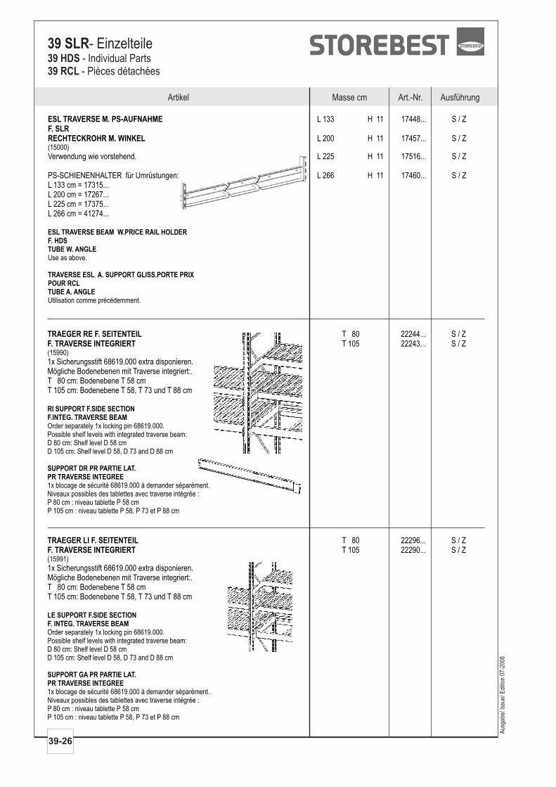
TRAVERSE HI. VORGEHAENGTF. SLRRECHTECKROHR M. WINKEL
L 266 T 6 H 8 52634... S / Z
Traverse hinten einzuhängen vor Rückwänden.Zur Auflage von Böden in Tiefenrichtungder Seitenteile.
(15948)
Rear traverse beam, hanging in front of back panels.To hold shelves in direction of the depth of theside sections.
REAR TRAV.BEAM HANG.FRONTF. HDSTUBE W. ANGLE
TRAVERSE HINTENF. SLRRECHTECKROHR M. WINKEL
L 133 H 8 21075... S / ZL 200 H 8 21104... S / ZL 225 H 8 21178... S / ZL 266 H 8 25478... S / Z
2x Sicherungsstift 68619.000 extra disponieren.Zur Auflage von Böden in Tiefenrichtungder Seitenteile. Die Oberkante entsprichtOK von Konsolen.
(15983)
Order separately 2x locking pin 68619.000.To hold shelves in direction of the depth of theside sections. The upper edge correspondswith the upper edges of the brackets.
2x blocage de sécurité 68619.000 à demander séparément.Pour le logement des tablettes dans le sens de laprofondeur des parties latérales. L'arrête supérieurecorrespond à l'arrête supérieure des consoles.
REAR TRAVERSE BEAMF. HDSTUBE W. ANGLE
TRAVERSE ARRIEREPOUR RCLTUBE A. ANGLE
H
Zulässige Höchstbelastungen:
L 133 cm = 1450 kgL 200 cm = 1450 kgL 225 cm = 1250 kgL 266 cm = 1000 kg
Permissible max. loads:Charges maximales admissibles :
AusführungMasse cm Art.-Nr.Artikel
Aus
gabe
/ Iss
ue/ E
ditio
n 07
-200
8
39-25
39 SLR- Einzelteile39 HDS
39 RCL- Individual Parts
- Pièces détachées
H
ESL TRAVERSE VORNF. SLR
L 133 H 11 96320... S / ZL 200 H 11 22789... S / ZL 225 H 11 15782... S / Z
2x Sicherungsstift 68619.000 extra disponieren. L 266 H 11 22788... S / ZFür ein elektronisches Preisauszeichnungs-System.In Verbindung mit Traverse hinten zur Auflage vonBöden in Tiefenrichtung der Seitenteile.Die Oberkante entspricht OK von Konsolen.
(15987)
Order separately 2x locking pin 68619.000.For electronic price marking/labeling system.In combination with traverse beam in rear to holdshelves in direction of the depth of the side sections.The upper edge corresponds with the upper edgesof the brackets.
2x blocage de sécurité 68619.000 à demander séparément.Pour un système électronique de distinction de prix.En liaison avec la traverse à l'arrière, pour lelogement des tablettes dans le sens de profondeurdes parties latérales. L'arête supérieure correspond àl'arête supérieure des consoles.
ESL FRONT TRAVERSE BEAMF. HDS
TRAVERSE ESL DEVANTPOUR RCL
Zulässige Höchstbelastungen:
L 133 cm = 1450 kgL 200 cm = 1450 kgL 225 cm = 1250 kgL 266 cm = 1000 kg
Permissible max. loads:Charges maximales admissibles :
TRAVERSE AR. ACCR. DEVANTPOUR RCLTUBE A. ANGLETraverse arrière, accrochage devant les panneauxde fond. Pour le logement des tablettes dans le sensde la profondeur des parties latérales.
Aus
gabe
/ Iss
ue/ E
ditio
n 07
-200
8
Artikel Masse cm Art.-Nr. Ausführung
39-26
39 SLR- Einzelteile39 HDS39 RCL
- Individual Parts- Pièces détachées
TRAEGER LI F. SEITENTEILF. TRAVERSE INTEGRIERT
T 80 22296... S / ZT 105 22290... S / Z
1x Sicherungsstift 68619.000 extra disponieren.Mögliche Bodenebenen mit Traverse integriert:.T 80 cm: Bodenebene T 58 cmT 105 cm: Bodenebene T 58, T 73 und T 88 cm
(15991)
Order separately 1x locking pin 68619.000.Possible shelf levels with integrated traverse beam:D 80 cm: Shelf level D 58 cmD 105 cm: Shelf level D 58, D 73 and D 88 cm
1x blocage de sécurité 68619.000 à demander séparément.Niveaux possibles des tablettes avec traverse intégrée :P 80 cm : niveau tablette P 58 cmP 105 cm : niveau tablette P 58, P 73 et P 88 cm
LE SUPPORT F.SIDE SECTIONF. INTEG. TRAVERSE BEAM
SUPPORT GA PR PARTIE LAT.PR TRAVERSE INTEGREE
TRAEGER RE F. SEITENTEILF. TRAVERSE INTEGRIERT
T 80 22244... S / ZT 105 22243... S / Z
1x Sicherungsstift 68619.000 extra disponieren.Mögliche Bodenebenen mit Traverse integriert:.T 80 cm: Bodenebene T 58 cmT 105 cm: Bodenebene T 58, T 73 und T 88 cm
(15990)
Order separately 1x locking pin 68619.000.Possible shelf levels with integrated traverse beam:D 80 cm: Shelf level D 58 cmD 105 cm: Shelf level D 58, D 73 and D 88 cm
1x blocage de sécurité 68619.000 à demander séparément.Niveaux possibles des tablettes avec traverse intégrée :P 80 cm : niveau tablette P 58 cmP 105 cm : niveau tablette P 58, P 73 et P 88 cm
RI SUPPORT F.SIDE SECTIONF.INTEG. TRAVERSE BEAM
SUPPORT DR PR PARTIE LAT.PR TRAVERSE INTEGREE
ESL TRAVERSE M. PS-AUFNAHMEF. SLRRECHTECKROHR M. WINKEL
L 133 H 11 17448... S / Z
Verwendung wie vorstehend.
L 200 H 11 17457... S / Z
L 225 H 11 17516... S / Z
PS-SCHIENENHALTER für Umrüstungen: L 266 H 11 17460... S / ZL 133 cm = 17315...L 200 cm = 17267...L 225 cm = 17375...L 266 cm = 41274...
(15000)
Use as above.
Utilisation comme précédemment.
ESL TRAVERSE BEAM W.PRICE RAIL HOLDERF. HDSTUBE W. ANGLE
TRAVERSE ESL A. SUPPORT GLISS.PORTE PRIXPOUR RCLTUBE A. ANGLE
AusführungMasse cm Art.-Nr.Artikel
Aus
gabe
/ Iss
ue/ E
ditio
n 07
-200
8
39-27
39 SLR- Einzelteile39 HDS
39 RCL- Individual Parts
- Pièces détachées
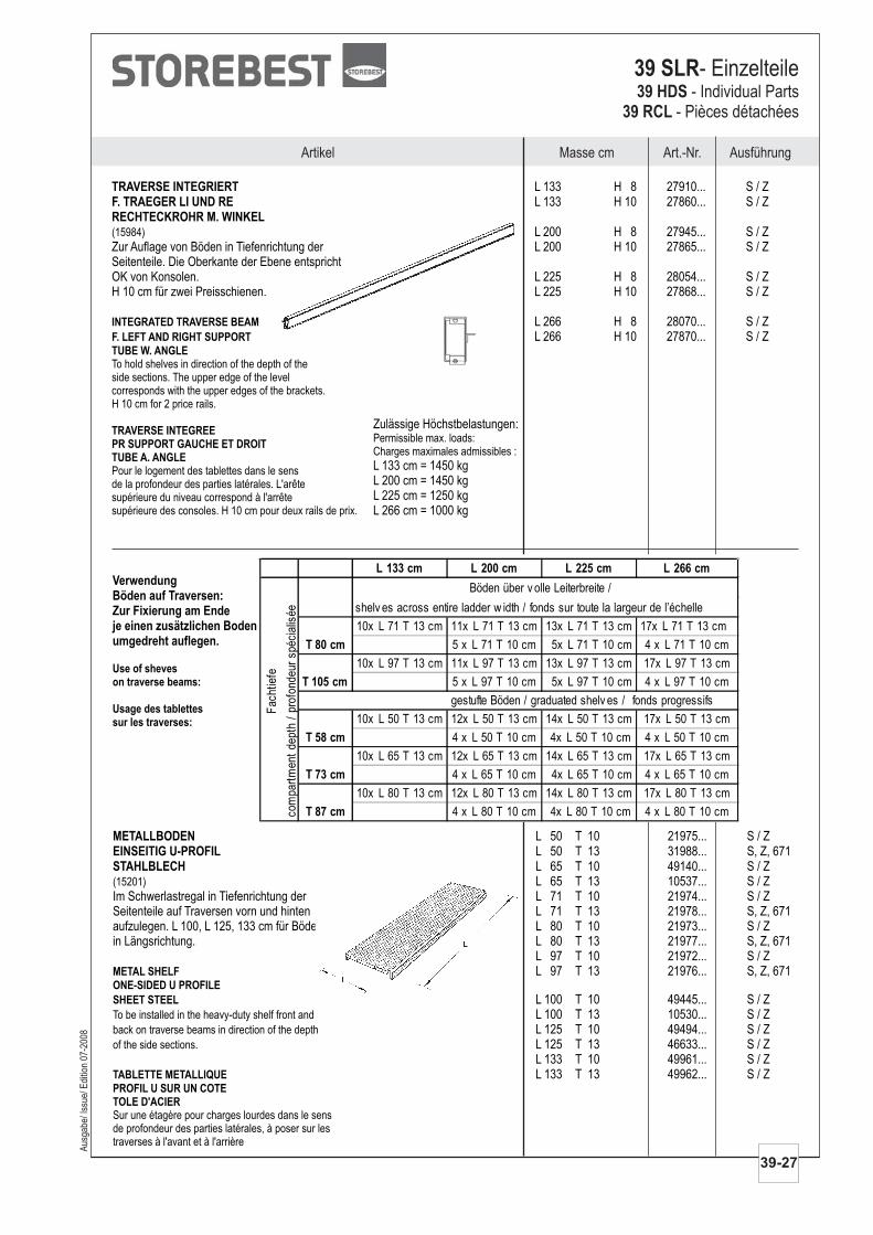
METALLBODENEINSEITIG U-PROFILSTAHLBLECH
L 50 T 10 21975... S / ZL 50 T 13 31988... S, Z, 671L 65 T 10 49140... S / ZL 65 T 13 10537... S / Z
Im Schwerlastregal in Tiefenrichtung der L 71 T 10 21974... S / ZSeitenteile auf Traversen vorn und hinten L 71 T 13 21978... S, Z, 671aufzulegen. L 100, L 125, 133 cm für Böden L 80 T 10 21973... S / Zin Längsrichtung. L 80 T 13 21977... S, Z, 671
L 97 T 10 21972... S / ZL 97 T 13 21976... S, Z, 671
L 100 T 10 49445... S / ZL 100 T 13 10530... S / ZL 125 T 10 49494... S / ZL 125 T 13 46633... S / ZL 133 T 10 49961... S / ZL 133 T 13 49962... S / Z
(15201)
To be installed in the heavy-duty shelf front and
back on traverse beams in direction of the depth
of the side sections.
Sur une étagère pour charges lourdes dans le sensde profondeur des parties latérales, à poser sur lestraverses à l'avant et à l'arrière
METAL SHELF
ONE-SIDED U PROFILE
SHEET STEEL
TABLETTE METALLIQUE
PROFIL U SUR UN COTETOLE D'ACIER
VerwendungBöden auf Traversen:Zur Fixierung am Endeje einen zusätzlichen Bodenumgedreht auflegen.
Use of sheveson traverse beams:
Usage des tablettessur les traverses:
L 133 cm L 200 cm L 225 cm L 266 cm
10x L 71 T 13 cm 11x L 71 T 13 cm 13x L 71 T 13 cm 17x L 71 T 13 cm
5 x L 71 T 10 cm 5x L 71 T 10 cm 4 x L 71 T 10 cm
10x L 97 T 13 cm 11x L 97 T 13 cm 13x L 97 T 13 cm 17x L 97 T 13 cm
5 x L 97 T 10 cm 5x L 97 T 10 cm 4 x L 97 T 10 cm
10x L 50 T 13 cm 12x L 50 T 13 cm 14x L 50 T 13 cm 17x L 50 T 13 cm
4 x L 50 T 10 cm 4x L 50 T 10 cm 4 x L 50 T 10 cm
10x L 65 T 13 cm 12x L 65 T 13 cm 14x L 65 T 13 cm 17x L 65 T 13 cm
4 x L 65 T 10 cm 4x L 65 T 10 cm 4 x L 65 T 10 cm
10x L 80 T 13 cm 12x L 80 T 13 cm 14x L 80 T 13 cm 17x L 80 T 13 cm
4 x L 80 T 10 cm 4x L 80 T 10 cm 4 x L 80 T 10 cm
Fac
htie
fe
com
part
men
tde
pth
/pr
ofon
deur
spéc
ialis
ée
T 87 cm
T 58 cm
T 73 cm
T 105 cm
gestufte Böden / graduated shelv es / fonds progressifs
T 80 cm
Böden über v olle Leiterbreite /
shelv es across entire ladder w idth / fonds sur toute la largeur de l’échelle
TRAVERSE INTEGRIERTF. TRAEGER LI UND RERECHTECKROHR M. WINKEL
L 133 H 8 27910... S / ZL 133 H 10 27860... S / Z
L 200 H 8 27945... S / ZZur Auflage von Böden in Tiefenrichtung der L 200 H 10 27865... S / ZSeitenteile. Die Oberkante der Ebene entsprichtOK von Konsolen. L 225 H 8 28054... S / ZH 10 cm für zwei Preisschienen. L 225 H 10 27868... S / Z
L 266 H 8 28070... S / ZL 266 H 10 27870... S / Z
(15984)
To hold shelves in direction of the depth of theside sections. The upper edge of the levelcorresponds with the upper edges of the brackets.H 10 cm for 2 price rails.
Pour le logement des tablettes dans le sensde la profondeur des parties latérales. L'arêtesupérieure du niveau correspond à l'arrêtesupérieure des consoles.
INTEGRATED TRAVERSE BEAM
F. LEFT AND RIGHT SUPPORT
TUBE W. ANGLE
TRAVERSE INTEGREEPR SUPPORT GAUCHE ET DROITTUBE A. ANGLE
H 10 cm pour deux rails de prix.
Zulässige Höchstbelastungen:
L 133 cm = 1450 kgL 200 cm = 1450 kgL 225 cm = 1250 kgL 266 cm = 1000 kg
Permissible max. loads:Charges maximales admissibles :
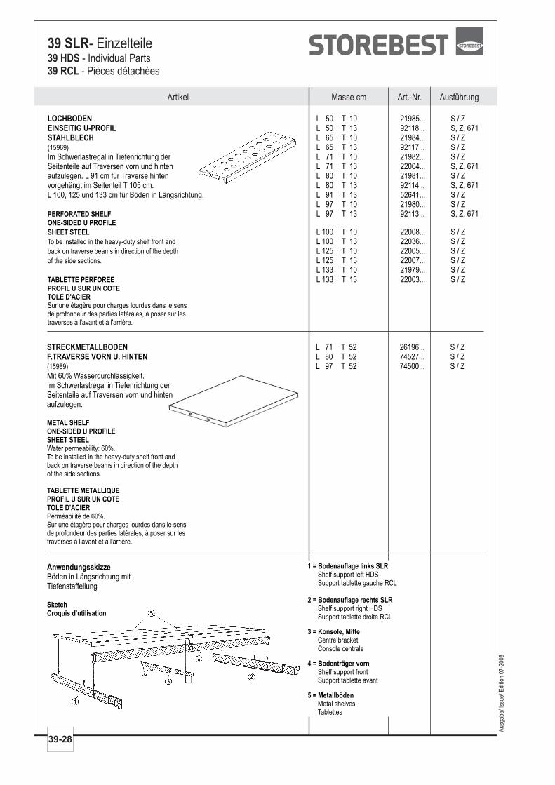
LOCHBODENEINSEITIG U-PROFILSTAHLBLECH
L 50 T 10 21985... S / ZL 50 T 13 92118... S, Z, 671L 65 T 10 21984... S / ZL 65 T 13 92117... S / Z
Im Schwerlastregal in Tiefenrichtung der L 71 T 10 21982... S / ZSeitenteile auf Traversen vorn und hinten L 71 T 13 22004... S, Z, 671aufzulegen. L 91 cm für Traverse hinten L 80 T 10 21981... S / Zvorgehängt im Seitenteil T 105 cm. L 80 T 13 92114... S, Z, 671L 100, 125 und 133 cm für Böden in Längsrichtung. L 91 T 13 52641... S / Z
L 97 T 10 21980... S / ZL 97 T 13 92113... S, Z, 671
L 100 T 10 22008... S / ZL 100 T 13 22036... S / ZL 125 T 10 22005... S / ZL 125 T 13 22007... S / ZL 133 T 10 21979... S / ZL 133 T 13 22003... S / Z
(15969)
To be installed in the heavy-duty shelf front and
back on traverse beams in direction of the depth
of the side sections.
Sur une étagère pour charges lourdes dans le sensde profondeur des parties latérales, à poser sur lestraverses à l'avant et à l'arrière.
PERFORATED SHELF
ONE-SIDED U PROFILE
SHEET STEEL
TABLETTE PERFOREE
PROFIL U SUR UN COTETOLE D'ACIER
Aus
gabe
/ Iss
ue/ E
ditio
n 07
-200
8
Artikel Masse cm Art.-Nr. Ausführung
39-28
39 SLR- Einzelteile39 HDS39 RCL
- Individual Parts- Pièces détachées
STRECKMETALLBODENF.TRAVERSE VORN U. HINTEN
L 71 T 52 26196... S / ZL 80 T 52 74527... S / ZL 97 T 52 74500... S / Z
Mit 60% Wasserdurchlässigkeit.Im Schwerlastregal in Tiefenrichtung derSeitenteile auf Traversen vorn und hintenaufzulegen.
(15989)
Water permeability: 60%.To be installed in the heavy-duty shelf front andback on traverse beams in direction of the depthof the side sections.
Perméabilité de 60%.Sur une étagère pour charges lourdes dans le sensde profondeur des parties latérales, à poser sur lestraverses à l'avant et à l'arrière.
METAL SHELFONE-SIDED U PROFILESHEET STEEL
TABLETTE METALLIQUEPROFIL U SUR UN COTETOLE D'ACIER
AnwendungsskizzeBöden in Längsrichtung mitTiefenstaffellung
SketchCroquis d’utilisation
1 = Bodenauflage links SLR
2 = Bodenauflage rechts SLR
3 = Konsole, Mitte
4 = Bodenträger vorn
5 = Metallböden
Shelf support left HDSSupport tablette gauche RCL
Shelf support right HDSSupport tablette droite RCL
Centre bracketConsole centrale
Shelf support frontSupport tablette avant
Metal shelvesTablettes
AusführungMasse cm Art.-Nr.Artikel
Aus
gabe
/ Iss
ue/ E
ditio
n 07
-200
8
39-29
39 SLR- Einzelteile39 HDS
39 RCL- Individual Parts
- Pièces détachées
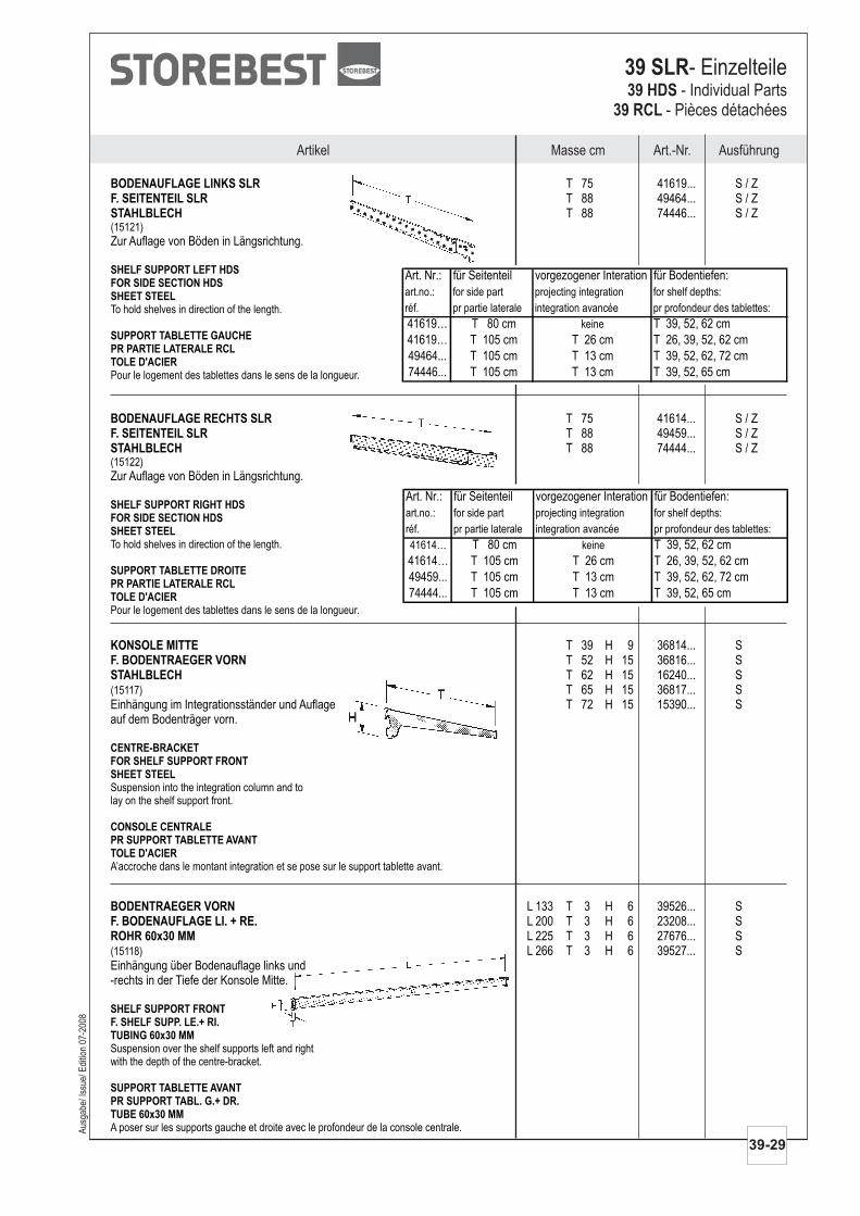
BODENAUFLAGE LINKS SLRF. SEITENTEIL SLRSTAHLBLECH
T 75 41619... S / ZT 88 49464... S / ZT 88 74446... S / Z
Zur Auflage von Böden in Längsrichtung.(15121)
To hold shelves in direction of the length.
Pour le logement des tablettes dans le sens de la longueur.
SHELF SUPPORT LEFT HDSFOR SIDE SECTION HDSSHEET STEEL
SUPPORT TABLETTE GAUCHEPR PARTIE LATERALE RCLTOLE D'ACIER
Art. Nr.: für Seitenteil vorgezogener Interation für Bodentiefen:
art.no.: for side part projecting integration for shelf depths:
réf. pr partie laterale integration avancée pr profondeur des tablettes:
41619… T 80 cm keine T 39, 52, 62 cm
41619… T 105 cm T 26 cm T 26, 39, 52, 62 cm
49464... T 105 cm T 13 cm T 39, 52, 62, 72 cm
74446... T 105 cm T 13 cm T 39, 52, 65 cm
BODENAUFLAGE RECHTS SLRF. SEITENTEIL SLRSTAHLBLECH
T 75 41614... S / ZT 88 49459... S / ZT 88 74444... S / Z
Zur Auflage von Böden in Längsrichtung.(15122)
To hold shelves in direction of the length.
Pour le logement des tablettes dans le sens de la longueur.
SHELF SUPPORT RIGHT HDSFOR SIDE SECTION HDSSHEET STEEL
SUPPORT TABLETTE DROITEPR PARTIE LATERALE RCLTOLE D'ACIER
Art. Nr.: für Seitenteil vorgezogener Interation für Bodentiefen:
art.no.: for side part projecting integration for shelf depths:
réf. pr partie laterale integration avancée pr profondeur des tablettes:
41614… T 80 cm keine T 39, 52, 62 cm
41614… T 105 cm T 26 cm T 26, 39, 52, 62 cm
49459... T 105 cm T 13 cm T 39, 52, 62, 72 cm
74444... T 105 cm T 13 cm T 39, 52, 65 cm
KONSOLE MITTEF. BODENTRAEGER VORNSTAHLBLECH
T 39 H 9 36814... ST 52 H 15 36816... ST 62 H 15 16240... ST 65 H 15 36817... S
Einhängung im Integrationsständer und Auflage T 72 H 15 15390... Sauf dem Bodenträger vorn.
(15117)
Suspension into the integration column and tolay on the shelf support front.
A’accroche dans le montant integration et se pose sur le support tablette avant.
CENTRE-BRACKETFOR SHELF SUPPORT FRONTSHEET STEEL
CONSOLE CENTRALEPR SUPPORT TABLETTE AVANTTOLE D'ACIER
BODENTRAEGER VORNF. BODENAUFLAGE LI. + RE.ROHR 60x30 MM
L 133 T 3 H 6 39526... SL 200 T 3 H 6 23208... SL 225 T 3 H 6 27676... SL 266 T 3 H 6 39527... S
Einhängung über Bodenauflage links und-rechts in der Tiefe der Konsole Mitte.
(15118)
Suspension over the shelf supports left and rightwith the depth of the centre-bracket.
A poser sur les supports gauche et droite avec le profondeur de la console centrale.
SHELF SUPPORT FRONTF. SHELF SUPP. LE.+ RI.TUBING 60x30 MM
SUPPORT TABLETTE AVANTPR SUPPORT TABL. G.+ DR.TUBE 60x30 MM
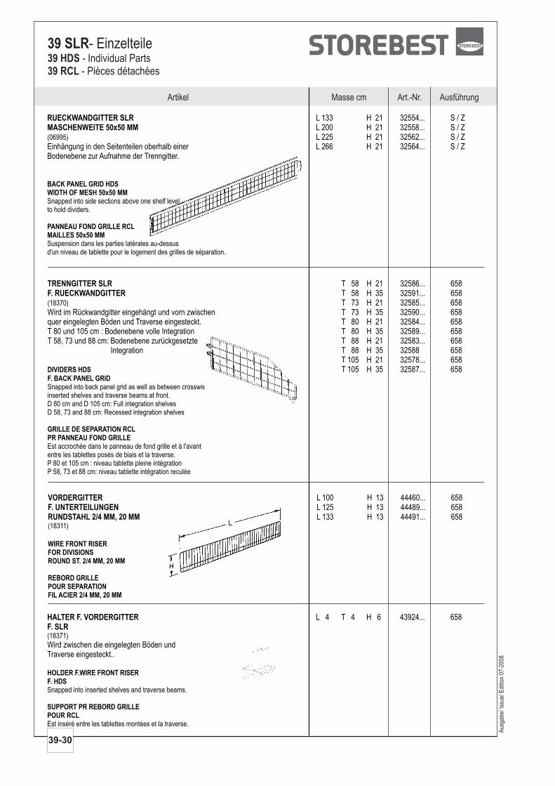
VORDERGITTERF. UNTERTEILUNGENRUNDSTAHL 2/4 MM, 20 MM
L 100 H 13 44460... 658L 125 H 13 44489... 658L 133 H 13 44491... 658
(18311)
WIRE FRONT RISERFOR DIVISIONSROUND ST. 2/4 MM, 20 MM
REBORD GRILLEPOUR SEPARATIONFIL ACIER 2/4 MM, 20 MM
TRENNGITTER SLRF. RUECKWANDGITTER
T 58 H 21 32586... 658T 58 H 35 32591... 658T 73 H 21 32585... 658
Wird im Rückwandgitter eingehängt und vorn zwischen T 73 H 35 32590... 658quer eingelegten Böden und Traverse eingesteckt. T 80 H 21 32584... 658T 80 und 105 cm : Bodenebene volle Integration T 80 H 35 32589... 658T 58, 73 und 88 cm: Bodenebene zurückgesetzte T 88 H 21 32583... 658
Integration T 88 H 35 32588 658T 105 H 21 32578... 658T 105 H 35 32587... 658
(18370)
Snapped into back panel grid as well as between crosswiseinserted shelves and traverse beams at front.D 80 cm and D 105 cm: Full integration shelvesD 58, 73 and 88 cm: Recessed integration shelves
Est accrochée dans le panneau de fond grille et à l'avantentre les tablettes posés de biais et la traverse.P 80 et 105 cm : niveau tablette pleine intégrationP 58, 73 et 88 cm: niveau tablette intégration reculée
DIVIDERS HDS
F. BACK PANEL GRID
GRILLE DE SEPARATION RCLPR PANNEAU FOND GRILLE
Artikel Masse cm Art.-Nr. Ausführung
39-30
39 SLR- Einzelteile39 HDS39 RCL
- Individual Parts- Pièces détachées
RUECKWANDGITTER SLRMASCHENWEITE 50x50 MM
L 133 H 21 32554... S / ZL 200 H 21 32558... S / ZL 225 H 21 32562... S / Z
Einhängung in den Seitenteilen oberhalb einer L 266 H 21 32564... S / ZBodenebene zur Aufnahme der Trenngitter.
(06995)
Snapped into side sections above one shelf levelto hold dividers.
Suspension dans les parties latérales au-dessusd'un niveau de tablette pour le logement des grilles de séparation.
BACK PANEL GRID HDSWIDTH OF MESH 50x50 MM
PANNEAU FOND GRILLE RCLMAILLES 50x50 MM
HALTER F. VORDERGITTERF. SLR
L 4 T 4 H 6 43924... 658
Wird zwischen die eingelegten Böden undTraverse eingesteckt..
(18371)
Snapped into inserted shelves and traverse beams.
Est inséré entre les tablettes montées et la traverse.
HOLDER F.WIRE FRONT RISERF. HDS
SUPPORT PR REBORD GRILLEPOUR RCL
Aus
gabe
/ Iss
ue/ E
ditio
n 07
-200
8
Masse cm Art.-Nr. AusführungArtikel
Aus
gabe
/ Iss
ue/ E
ditio
n 07
-200
8
39-31
39 SLR- Einzelteile39 HDS
39 RCL- Individual Parts
- Pièces détachées
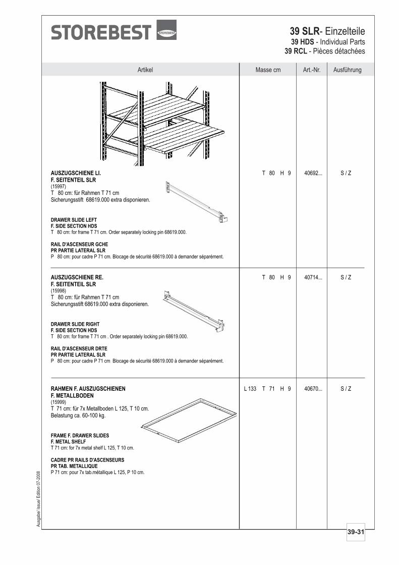
AUSZUGSCHIENE LI.F. SEITENTEIL SLR
T 80 H 9 40692... S / Z
T 80 cm: für Rahmen T 71 cmSicherungsstift 68619.000 extra disponieren.
(15997)
T 80 cm: for frame T 71 cm. Order separately locking pin 68619.000.
P 80 cm: pour cadre P 71 cm. Blocage de sécurité 68619.000 à demander séparément.
DRAWER SLIDE LEFTF. SIDE SECTION HDS
RAIL D'ASCENSEUR GCHEPR PARTIE LATERAL SLR
AUSZUGSCHIENE RE.F. SEITENTEIL SLR
T 80 H 9 40714... S / Z
T 80 cm: für Rahmen T 71 cmSicherungsstift 68619.000 extra disponieren.
(15998)
T 80 cm: for frame T 71 cm . Order separately locking pin 68619.000.
P 80 cm: pour cadre P 71 cm Blocage de sécurité 68619.000 à demander séparément.
DRAWER SLIDE RIGHTF. SIDE SECTION HDS
RAIL D'ASCENSEUR DRTEPR PARTIE LATERAL SLR
RAHMEN F. AUSZUGSCHIENENF. METALLBODEN
L 133 T 71 H 9 40670... S / Z
T 71 cm: für 7x Metallboden L 125, T 10 cm.Belastung ca. 60-100 kg.
(15999)
T 71 cm: for 7x metal shelf L 125, T 10 cm.
P 71 cm: pour 7x tab.métallique L 125, P 10 cm.
FRAME F. DRAWER SLIDESF. METAL SHELF
CADRE PR RAILS D'ASCENSEURSPR TAB. METALLIQUE
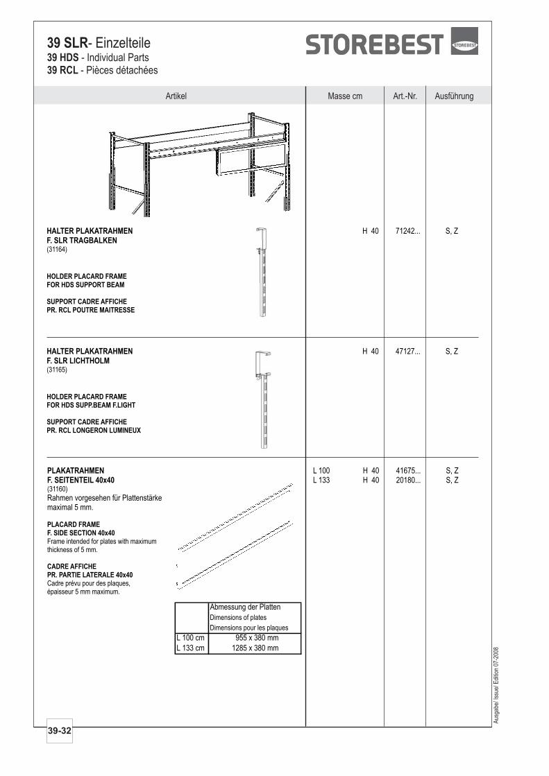
PLAKATRAHMENF. SEITENTEIL 40x40
L 100 H 40 41675... S, ZL 133 H 40 20180... S, Z
Rahmen vorgesehen für Plattenstärkemaximal 5 mm.
(31160)
Frame intended for plates with maximumthickness of 5 mm.
Cadre prévu pour des plaques,épaisseur 5 mm maximum.
PLACARD FRAMEF. SIDE SECTION 40x40
CADRE AFFICHEPR. PARTIE LATERALE 40x40
HALTER PLAKATRAHMENF. SLR TRAGBALKEN
H 40 71242... S, Z
(31164)
HOLDER PLACARD FRAMEFOR HDS SUPPORT BEAM
SUPPORT CADRE AFFICHEPR. RCL POUTRE MAITRESSE
HALTER PLAKATRAHMENF. SLR LICHTHOLM
H 40 47127... S, Z
(31165)
HOLDER PLACARD FRAMEFOR HDS SUPP.BEAM F.LIGHT
SUPPORT CADRE AFFICHEPR. RCL LONGERON LUMINEUX
Abmessung der Platten
Dimensions of plates
Dimensions pour les plaques
L 100 cm 955 x 380 mm
L 133 cm 1285 x 380 mm
Artikel Masse cm Art.-Nr. Ausführung
39-32
39 SLR- Einzelteile39 HDS39 RCL
- Individual Parts- Pièces détachées
Aus
gabe
/ Iss
ue/ E
ditio
n 07
-200
8
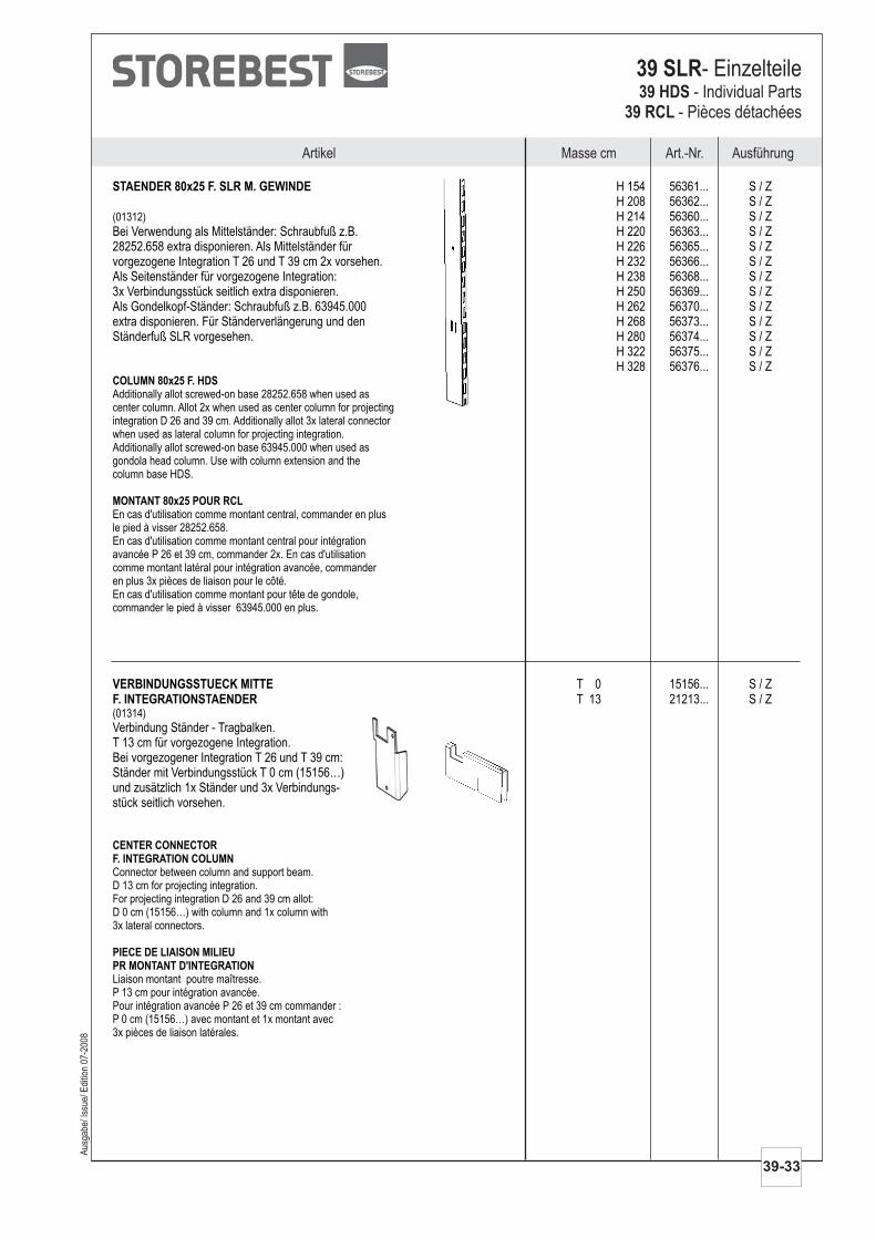
VERBINDUNGSSTUECK MITTEF. INTEGRATIONSTAENDER
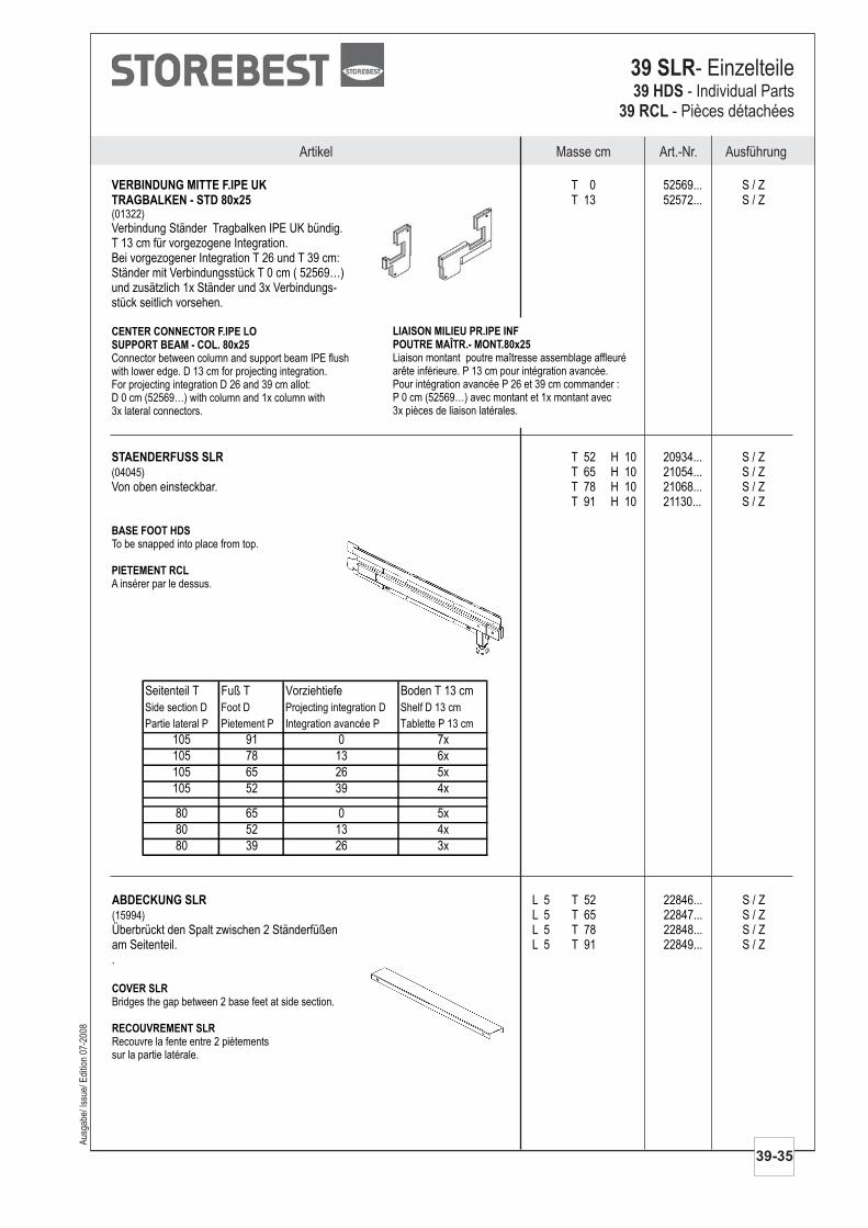
T 0 15156... S / ZT 13 21213... S / Z
Verbindung Ständer - Tragbalken.T 13 cm für vorgezogene Integration.Bei vorgezogener Integration T 26 und T 39 cm:Ständer mit Verbindungsstück T 0 cm (15156…)und zusätzlich 1x Ständer und 3x Verbindungs-stück seitlich vorsehen.
(01314)
Connector between column and support beam.D 13 cm for projecting integration.For projecting integration D 26 and 39 cm allot:D 0 cm (15156…) with column and 1x column with3x lateral connectors.
Liaison montant poutre maîtresse.P 13 cm pour intégration avancée.Pour intégration avancée P 26 et 39 cm commander :P 0 cm (15156…) avec montant et 1x montant avec3x pièces de liaison latérales.
CENTER CONNECTORF. INTEGRATION COLUMN
PIECE DE LIAISON MILIEUPR MONTANT D'INTEGRATION
Masse cm Art.-Nr. AusführungArtikel
Aus
gabe
/ Iss
ue/ E
ditio
n 07
-200
8
39-33
39 SLR- Einzelteile39 HDS
39 RCL- Individual Parts
- Pièces détachées
STAENDER 80x25 F. SLR M. GEWINDE H 154 56361... S / ZH 208 56362... S / ZH 214 56360... S / Z
Bei Verwendung als Mittelständer: Schraubfuß z.B. H 220 56363... S / Z28252.658 extra disponieren. Als Mittelständer für H 226 56365... S / Zvorgezogene Integration T 26 und T 39 cm 2x vorsehen. H 232 56366... S / ZAls Seitenständer für vorgezogene Integration: H 238 56368... S / Z3x Verbindungsstück seitlich extra disponieren. H 250 56369... S / ZAls Gondelkopf-Ständer: Schraubfuß z.B. 63945.000 H 262 56370... S / Zextra disponieren. Für Ständerverlängerung und den H 268 56373... S / ZStänderfuß SLR vorgesehen. H 280 56374... S / Z
H 322 56375... S / ZH 328 56376... S / Z
(01312)
Additionally allot screwed-on base 28252.658 when used ascenter column. Allot 2x when used as center column for projectingintegration D 26 and 39 cm. Additionally allot 3x lateral connectorwhen used as lateral column for projecting integration.Additionally allot screwed-on base 63945.000 when used asgondola head column. Use with column extension and thecolumn base HDS.
En cas d'utilisation comme montant central, commander en plusle pied à visser 28252.658.En cas d'utilisation comme montant central pour intégrationavancée P 26 et 39 cm, commander 2x. En cas d'utilisationcomme montant latéral pour intégration avancée, commanderen plus 3x pièces de liaison pour le côté.En cas d'utilisation comme montant pour tête de gondole,commander le pied à visser 63945.000 en plus.
COLUMN 80x25 F. HDS
MONTANT 80x25 POUR RCL
Artikel Masse cm Art.-Nr. Ausführung
39-34
39 SLR- Einzelteile39 HDS39 RCL
- Individual Parts- Pièces détachées
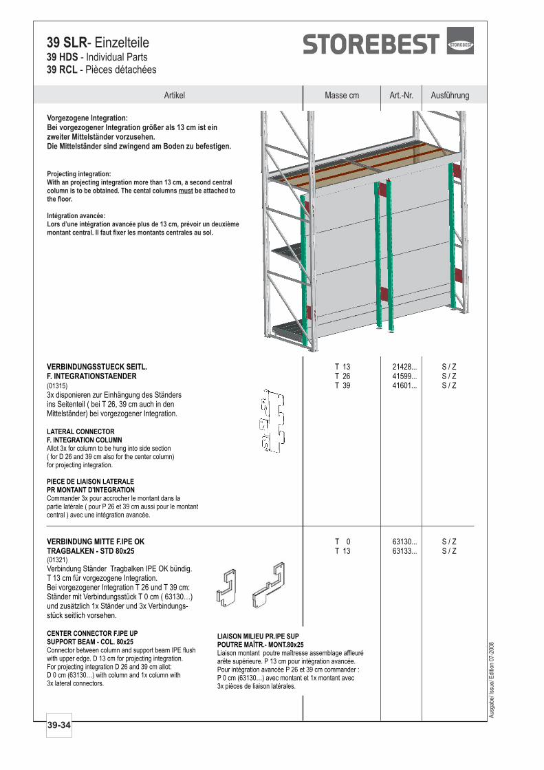
VERBINDUNGSSTUECK SEITL.F. INTEGRATIONSTAENDER
T 13 21428... S / ZT 26 41599... S / ZT 39 41601... S / Z
3x disponieren zur Einhängung des Ständersins Seitenteil ( bei T 26, 39 cm auch in denMittelständer) bei vorgezogener Integration.
(01315)
Allot 3x for column to be hung into side section( for D 26 and 39 cm also for the center column)for projecting integration.
Commander 3x pour accrocher le montant dans lapartie latérale ( pour P 26 et 39 cm aussi pour le montantcentral ) avec une intégration avancée.
LATERAL CONNECTORF. INTEGRATION COLUMN
PIECE DE LIAISON LATERALEPR MONTANT D'INTEGRATION
Vorgezogene Integration:Bei vorgezogener Integration größer als 13 cm ist einzweiter Mittelständer vorzusehen.Die Mittelständer sind zwingend am Boden zu befestigen.
Projecting integration:With an projecting integration more than 13 cm, a second centralcolumn is to be obtained. The cental columns be attached tothe floor.
Intégration avancée:Lors d’une intégration avancée plus de 13 cm, prévoir un deuxièmemontant central. Il faut fixer les montants centrales au sol.
must
VERBINDUNG MITTE F.IPE OKTRAGBALKEN - STD 80x25
T 0 63130... S / ZT 13 63133... S / Z
Verbindung Ständer Tragbalken IPE OK bündig.T 13 cm für vorgezogene Integration.Bei vorgezogener Integration T 26 und T 39 cm:Ständer mit Verbindungsstück T 0 cm ( 63130…)und zusätzlich 1x Ständer und 3x Verbindungs-stück seitlich vorsehen.
(01321)
Connector between column and support beam IPE flushwith upper edge. D 13 cm for projecting integration.For projecting integration D 26 and 39 cm allot:D 0 cm (63130…) with column and 1x column with3x lateral connectors.
CENTER CONNECTOR F.IPE UPSUPPORT BEAM - COL. 80x25
LIAISON MILIEU PR.IPE SUPPOUTRE MAÎTR.- MONT.80x25Liaison montant poutre maîtresse assemblage affleuréarête supérieure. P 13 cm pour intégration avancée.Pour intégration avancée P 26 et 39 cm commander :P 0 cm (63130…) avec montant et 1x montant avec3x pièces de liaison latérales.
Aus
gabe
/ Iss
ue/ E
ditio
n 07
-200
8
Masse cm Art.-Nr. AusführungArtikel
Aus
gabe
/ Iss
ue/ E
ditio
n 07
-200
8
39-35
39 SLR- Einzelteile39 HDS
39 RCL- Individual Parts
- Pièces détachées
ABDECKUNG SLR
Überbrückt den Spalt zwischen 2
.
L 5 T 52 22846... S / ZL 5 T 65 22847... S / Z
Ständerfüßen L 5 T 78 22848... S / Zam Seitenteil. L 5 T 91 22849... S / Z
(15994)
Bridges the gap between 2 at side section.
Recouvre la fente entre 2sur la partie latérale.
COVER SLR
RECOUVREMENT SLR
base feet
piètements
VERBINDUNG MITTE F.IPE UKTRAGBALKEN - STD 80x25
T 0 52569... S / ZT 13 52572... S / Z
Verbindung Ständer Tragbalken IPE UK bündig.T 13 cm für vorgezogene Integration.Bei vorgezogener Integration T 26 und T 39 cm:Ständer mit Verbindungsstück T 0 cm ( 52569…)und zusätzlich 1x Ständer und 3x Verbindungs-stück seitlich vorsehen.
(01322)
Connector between column and support beam IPE flushwith lower edge. D 13 cm for projecting integration.For projecting integration D 26 and 39 cm allot:D 0 cm (52569…) with column and 1x column with3x lateral connectors.
CENTER CONNECTOR F.IPE LOSUPPORT BEAM - COL. 80x25
LIAISON MILIEU PR.IPE INFPOUTRE MAÎTR.- MONT.80x25Liaison montant poutre maîtresse assemblage affleuréarête inférieure. P 13 cm pour intégration avancée.Pour intégration avancée P 26 et 39 cm commander :P 0 cm (52569…) avec montant et 1x montant avec3x pièces de liaison latérales.
STAENDERFUSS SLR T 52 H 10 20934... S / ZT 65 H 10 21054... S / Z
Von oben einsteckbar. T 78 H 10 21068... S / ZT 91 H 10 21130... S / Z
(04045)
To be snapped into place from top.
A insérer par le dessus.
BASE FOOT HDS
PIETEMENT RCL
Seitenteil T Fuß T Vorziehtiefe Boden T 13 cm
Side section D Foot D Projecting integration D Shelf D 13 cm
Partie lateral P Pietement P Integration avancée P Tablette P 13 cm
105 91 0 7x
105 78 13 6x
105 65 26 5x
105 52 39 4x
80 65 0 5x
80 52 13 4x
80 39 26 3x
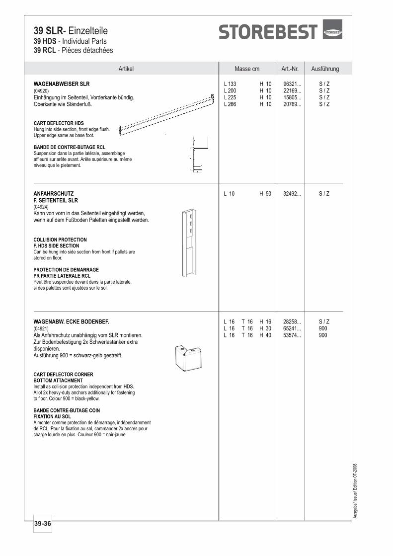
WAGENABWEISER SLR L 133 H 10 96321... S / ZL 200 H 10 22169... S / Z
Einhängung im Seitenteil, Vorderkante bündig. L 225 H 10 15805... S / ZOberkante wie Ständerfuß. L 266 H 10 20769... S / Z
(04920)
Hung into side section, front edge flush.Upper edge same as base foot.
Suspension dans la partie latérale, assemblageaffleuré sur arête avant. Arête supérieure au mêmeniveau que le pietement.
CART DEFLECTOR HDS
BANDE DE CONTRE-BUTAGE RCL
ANFAHRSCHUTZF. SEITENTEIL SLR
L 10 H 50 32492... S / Z
Kann von vorn in das Seitenteil eingehängt werden,wenn auf dem Fußboden Paletten eingestellt werden.
(04924)
Can be hung into side section from front if pallets arestored on floor.
Peut être suspendue devant dans la partie latérale,si des palettes sont ajustées sur le sol.
COLLISION PROTECTIONF. HDS SIDE SECTION
PROTECTION DE DEMARRAGEPR PARTIE LATERALE RCL
WAGENABW. ECKE BODENBEF. L 16 T 16 H 16 28258... S / ZL 16 T 16 H 30 65241... 900
Als Anfahrschutz unabhängig vom SLR montieren. L 16 T 16 H 40 53574... 900Zur Bodenbefestigung 2x Schwerlastanker extradisponieren.Ausführung 900 = schwarz-gelb gestreift.
(04921)
Install as collision protection independent from HDS.Allot 2x heavy-duty anchors additionally for fasteningto floor. Colour 900 = black-yellow.
A monter comme protection de démarrage, indépendammentde RCL. Pour la fixation au sol, commander 2x ancres pourcharge lourde en plus. Couleur 900 = noir-jaune.
CART DEFLECTOR CORNERBOTTOM ATTACHMENT
BANDE CONTRE-BUTAGE COINFIXATION AU SOL
Artikel Masse cm Art.-Nr. Ausführung
39-36
39 SLR- Einzelteile39 HDS39 RCL
- Individual Parts- Pièces détachées
Aus
gabe
/ Iss
ue/ E
ditio
n 07
-200
8
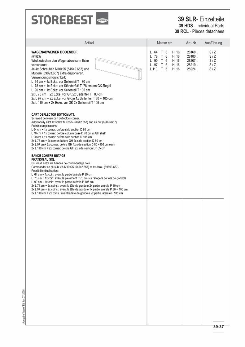
Aus
gabe
/ Iss
ue/ E
ditio
n 07
-200
8
Masse cm Art.-Nr. AusführungArtikel
39-37
39 SLR- Einzelteile39 HDS
39 RCL- Individual Parts
- Pièces détachées
WAGENABWEISER BODENBEF. L 64 T 6 H 16 28168... S / ZL 78 T 6 H 16 28180... S / Z
Wird zwischen den Wagenabweisern Ecke L 90 T 6 H 16 28207... S / Zverschraubt. L 97 T 6 H 16 28219... S / ZJe 4x Schrauben M10x25 (54542.657) und L 110 T 6 H 16 28224... S / ZMuttern (69893.657) extra disponieren.Verwendungsmöglichkeit:L 64 cm + 1x Ecke: vor Seitenteil T 80 cmL 78 cm + 1x Ecke: vor Ständerfuß T 78 cm am GK-RegalL 90 cm + 1x Ecke: vor Seitenteil T 105 cm2x L 78 cm + 2x Ecke: vor GK 2x Seitenteil T 80 cm2x L 97 cm + 2x Ecke: vor GK je 1x Seitenteil T 80 + 105 cm2x L 110 cm + 2x Ecke: vor GK 2x Seitenteil T 105 cm
(04923)
Screwed between cart deflectors corner.Additionally allot 4x screw M10x25 (54542.657) and 4x nut (69893.657).Possible applications:L 64 cm + 1x corner: before side section D 80 cmL 78 cm + 1x corner: before column base D 78 cm at GH shelfL 90 cm + 1x corner: before side section D 105 cm2x L 78 cm + 2x corner: before GH 2x side section D 80 cm2x L 97 cm+ 2x corner: before GH 1x side section D 80 +105 cm each2x L 110 cm + 2x corner: before GH 2x side section D 105 cm
Est vissé entre les bandes de contre-butage coin.Commander en plus 4x vis M10x25 (54542.657) et 4x écrou (69893.657).Possibilité d'utilisation :L 64 cm + 1x coin: avant la partie latérale P 80 cmL 78 cm + 1x coin: avant le piètement P 78 cm sur l'étagère de tête de gondoleL 90 cm + 1x coin: avant la partie latérale P 105 cm2x L 78 cm + 2x coins : avant la tête de gondole 2x partie latérale P 80 cm2x L 97 cm + 2x coins : avant la tête de gondole 1x partie latérale P 80 + 105 cm2x L 110 cm + 2x coins : avant la tête de gondole 2x partie latérale P 105 cm
CART DEFLECTOR BOTTOM ATT.
BANDE CONTRE-BUTAGEFIXATION AU SOL
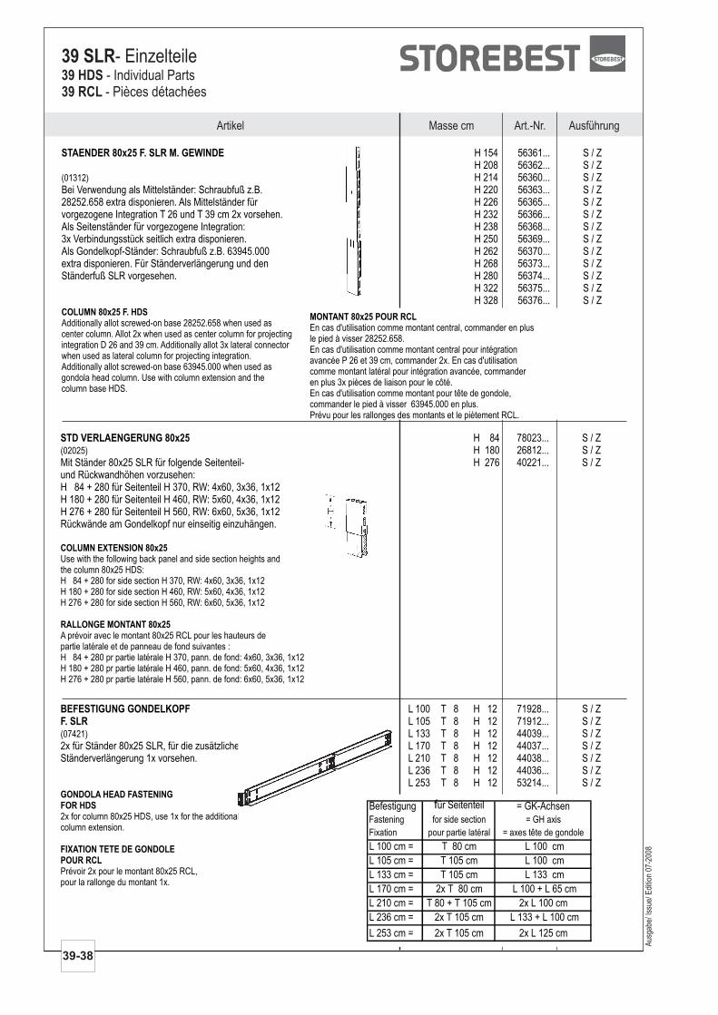
STAENDER 80x25 F. SLR M. GEWINDE H 154 56361... S / ZH 208 56362... S / ZH 214 56360... S / Z
Bei Verwendung als Mittelständer: Schraubfuß z.B. H 220 56363... S / Z28252.658 extra disponieren. Als Mittelständer für H 226 56365... S / Zvorgezogene Integration T 26 und T 39 cm 2x vorsehen. H 232 56366... S / ZAls Seitenständer für vorgezogene Integration: H 238 56368... S / Z3x Verbindungsstück seitlich extra disponieren. H 250 56369... S / ZAls Gondelkopf-Ständer: Schraubfuß z.B. 63945.000 H 262 56370... S / Zextra disponieren. Für Ständerverlängerung und den H 268 56373... S / ZStänderfuß SLR vorgesehen. H 280 56374... S / Z
H 322 56375... S / ZH 328 56376... S / Z
(01312)
Additionally allot screwed-on base 28252.658 when used ascenter column. Allot 2x when used as center column for projectingintegration D 26 and 39 cm. Additionally allot 3x lateral connectorwhen used as lateral column for projecting integration.Additionally allot screwed-on base 63945.000 when used asgondola head column. Use with column extension and thecolumn base HDS.
COLUMN 80x25 F. HDS
Artikel Masse cm Art.-Nr. Ausführung
39-38
39 SLR- Einzelteile39 HDS39 RCL
- Individual Parts- Pièces détachées
Aus
gabe
/ Iss
ue/ E
ditio
n 07
-200
8
STD VERLAENGERUNG 80x25 H 84 78023... S / ZH 180 26812... S / Z
Mit Ständer 80x25 SLR für folgende Seitenteil- H 276 40221... S / Zund Rückwandhöhen vorzusehen:H 84 + 280 für Seitenteil H 370, RW: 4x60, 3x36, 1x12H 180 + 280 für Seitenteil H 460, RW: 5x60, 4x36, 1x12H 276 + 280 für Seitenteil H 560, RW: 6x60, 5x36, 1x12Rückwände am Gondelkopf nur einseitig einzuhängen.
(02025)
Use with the following back panel and side section heights andthe column 80x25 HDS:H 84 + 280 for side section H 370, RW: 4x60, 3x36, 1x12H 180 + 280 for side section H 460, RW: 5x60, 4x36, 1x12H 276 + 280 for side section H 560, RW: 6x60, 5x36, 1x12
A prévoir avec le montant 80x25 RCL pour les hauteurs departie latérale et de panneau de fond suivantes :H 84 + 280 pr partie latérale H 370, pann. de fond: 4x60, 3x36, 1x12H 180 + 280 pr partie latérale H 460, pann. de fond: 5x60, 4x36, 1x12H 276 + 280 pr partie latérale H 560, pann. de fond: 6x60, 5x36, 1x12
COLUMN EXTENSION 80x25
RALLONGE MONTANT 80x25
BEFESTIGUNG GONDELKOPFF. SLR
L 100 T 8 H 12 71928... S / ZL 105 T 8 H 12 71912... S / ZL 133 T 8 H 12 44039... S / Z
2x für Ständer 80x25 SLR, für die zusätzliche L 170 T 8 H 12 44037... S / ZStänderverlängerung 1x vorsehen. L 210 T 8 H 12 44038... S / Z
L 236 T 8 H 12 44036... S / ZL 253 T 8 H 12 53214... S / Z
(07421)
2x for column 80x25 HDS, use 1x for the additionalcolumn extension.
Prévoir 2x pour le montant 80x25 RCL,pour la rallonge du montant 1x.
GONDOLA HEAD FASTENINGFOR HDS
FIXATION TETE DE GONDOLEPOUR RCL
Befestigung für Seitenteil = GK-Achsen
Fastening for side section = GH axis
Fixation pour partie latéral = axes tête de gondole
L 100 cm = T 80 cm L 100 cm
L 105 cm = T 105 cm L 100 cm
L 133 cm = T 105 cm L 133 cm
L 170 cm = 2x T 80 cm L 100 + L 65 cm
L 210 cm = T 80 + T 105 cm 2x L 100 cm
L 236 cm = 2x T 105 cm L 133 + L 100 cm
L 253 cm = 2x T 105 cm 2x L 125 cm
MONTANT 80x25 POUR RCLEn cas d'utilisation comme montant central, commander en plusle pied à visser 28252.658.En cas d'utilisation comme montant central pour intégrationavancée P 26 et 39 cm, commander 2x. En cas d'utilisationcomme montant latéral pour intégration avancée, commanderen plus 3x pièces de liaison pour le côté.En cas d'utilisation comme montant pour tête de gondole,commander le pied à visser 63945.000 en plus.Prévu pour les rallonges des montants et le piètement RCL.
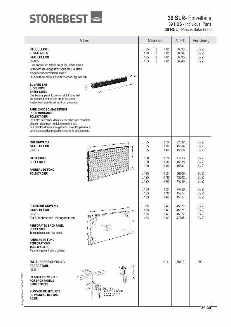
Aus
gabe
/ Iss
ue/ E
ditio
n 07
-200
8
Masse cm Art.-Nr. AusführungArtikel
39-39
39 SLR- Einzelteile39 HDS
39 RCL- Individual Parts
- Pièces détachées
STOSSLEISTEF. STAENDERSTAHLBLECH
L 65 T 3 H 12 86693... S / ZL 100 T 3 H 12 86694... S / ZL 125 T 3 H 12 86695... S / ZL 133 T 3 H 12 86948... S / Z
Einhängbar im Ständerschlitz, wenn keineStänderfüße eingesetzt sondern Paletteneingeschoben werden sollen.Rückwände mittels Aushebsicherung fixieren.
(04472)
Can be snapped into column slot if base feetare not used and pallets are to be stored.Fasten back panels using lift-out preventer.
Peut être accrochée dans les encoches des montantssi aucun pietement ne doit être utilisé et sides palettes doivent être glissées. Fixer les panneauxde fonds avec des protections contre le soulèvement.
BUMPER BARF. COLUMNSSHEET STEEL
PARE-CHOC SOUBASSEMENTPOUR MONTANTSTOLE D'ACIER
RUECKWANDSTAHLBLECH
L 65 H 24 92812... S / ZL 65 H 36 45634... S / ZL 65 H 60 45866... S / Z
L 100 H 24 17233... S / ZL 100 H 36 45635... S / ZL 100 H 60 45641... S / Z
L 125 H 24 36266... S / ZL 125 H 36 45642... S / ZL 125 H 60 45636... S / Z
L 133 H 24 74726... S / ZL 133 H 36 45977... S / ZL 133 H 60 45637... S / Z
(06101)
BACK PANEL
SHEET STEEL
PANNEAU DE FOND
TOLE D'ACIER
LOCH-RUECKWANDSTAHLBLECH
L 65 H 60 45670... S / ZL 100 H 60 45671... S / ZL 125 H 60 45672... S / Z
Zur Aufnahme der Hakengarnituren. L 133 H 60 47785... S / Z(06501)
To snap hook sets into place.
Pour le logement des crochets.
PERFORATED BACK PANELSHEET STEEL
PANNEAU DE FONDPERFORATIONSTOLE D'ACIER
RW-AUSHEBSICHERUNGFEDERSTAHL
H 4 35113... 000
(06261)
LIFT-OUT PREVENTERFOR BACK PANELSSPRING STEEL
BLOCAGE DE SECURITEPR PANNEAU DE FONDACIER
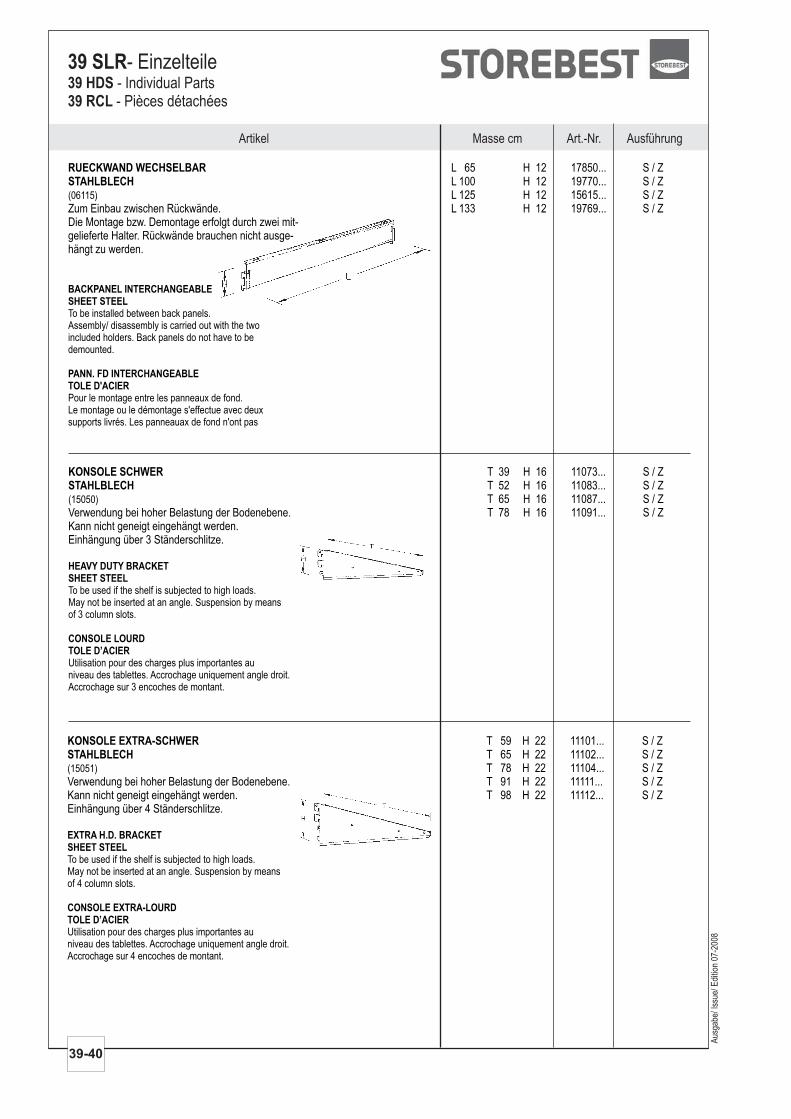
Artikel Masse cm Art.-Nr. Ausführung
39-40
39 SLR- Einzelteile39 HDS39 RCL
- Individual Parts- Pièces détachées
RUECKWAND WECHSELBARSTAHLBLECH
L 65 H 12 17850... S / ZL 100 H 12 19770... S / ZL 125 H 12 15615... S / Z
Zum Einbau zwischen Rückwände. L 133 H 12 19769... S / ZDie Montage bzw. Demontage erfolgt durch zwei mit-gelieferte Halter. Rückwände brauchen nicht ausge-hängt zu werden.
(06115)
To be installed between back panels.Assembly/ disassembly is carried out with the twoincluded holders. Back panels do not have to bedemounted.
Pour le montage entre les panneaux de fond.Le montage ou le démontage s'effectue avec deuxsupports livrés. Les panneauax de fond n'ont pas
BACKPANEL INTERCHANGEABLESHEET STEEL
PANN. FD INTERCHANGEABLETOLE D'ACIER
KONSOLE SCHWERSTAHLBLECH
T 39 H 16 11073... S / ZT 52 H 16 11083... S / ZT 65 H 16 11087... S / Z
Verwendung bei hoher Belastung der Bodenebene. T 78 H 16 11091... S / ZKann nicht geneigt eingehängt werden.Einhängung über 3 Ständerschlitze.
(15050)
To be used if the shelf is subjected to high loads.May not be inserted at an angle. Suspension by meansof 3 column slots.
Utilisation pour des charges plus importantes auniveau des tablettes. Accrochage uniquement angle droit.Accrochage sur 3 encoches de montant.
HEAVY DUTY BRACKETSHEET STEEL
CONSOLE LOURDTOLE D’ACIER
KONSOLE EXTRA-SCHWERSTAHLBLECH
T 59 H 22 11101... S / ZT 65 H 22 11102... S / ZT 78 H 22 11104... S / Z
Verwendung bei hoher Belastung der Bodenebene. T 91 H 22 11111... S / ZKann nicht geneigt eingehängt werden. T 98 H 22 11112... S / ZEinhängung über 4 Ständerschlitze.
(15051)
To be used if the shelf is subjected to high loads.May not be inserted at an angle. Suspension by meansof 4 column slots.
Utilisation pour des charges plus importantes auniveau des tablettes. Accrochage uniquement angle droit.Accrochage sur 4 encoches de montant.
EXTRA H.D. BRACKETSHEET STEEL
CONSOLE EXTRA-LOURDTOLE D’ACIER
Aus
gabe
/ Iss
ue/ E
ditio
n 07
-200
8
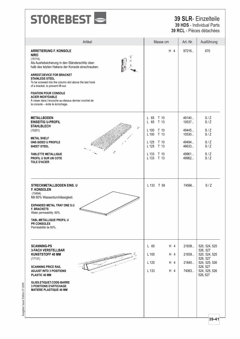
Masse cm Art.-Nr. AusführungArtikel
Aus
gabe
/ Iss
ue/ E
ditio
n 07
-200
8
39-41
39 SLR- Einzelteile39 HDS
39 RCL- Individual Parts
- Pièces détachées
ARRETIERUNG F. KONSOLENIRO
H 4 97216... 670
Als Aushebsicherung in den Ständerschlitz ober-halb des letzten Hakens der Konsole einschrauben.
(15114)
To be screwed into the column slot above the last hookof a bracket, to prevent lift-out.
À visser dans l’encoche au-dessus dernier crochet dela console – évite le écrochage.
ARREST.DEVICE FOR BRACKETSTAINLESS STEEL
FIXATION POUR CONSOLEACIER INOXYDABLE
METALLBODENEINSEITIG U-PROFILSTAHLBLECH
L 65 T 10 49140... S / ZL 65 T 13 10537... S / Z
L 100 T 10 49445... S / ZL 100 T 13 10530... S / Z
L 125 T 10 49494... S / ZL 125 T 13 46633... S / Z
L 133 T 10 49961... S / ZL 133 T 13 49962... S / Z
(15201)
METAL SHELF
ONE-SIDED U PROFILE
SHEET STEEL
TABLETTE METALLIQUE
PROFIL U SUR UN COTE
TOLE D'ACIER
STRECKMETALLBODEN EINS. UF. KONSOLEN
L 133 T 59 74566... S / Z
Mit 60% Wasserdurchlässigkeit.(15494)
Water permeability: 60%.
Perméabilité de 60%.
EXPANDED METAL TRAY ONE S.UF. BRACKETS
TABL.METALLIQUE PROFIL UPR CONSOLES
SCANNING-PS3-FACH VERSTELLBARKUNSTSTOFF 40 MM
L 65 H 4 21838... 520, 524, 525526, 527
L 100 H 4 21839... 520, 524, 525526, 527
L 125 H 4 21840... 524, 525, 526526, 527
L 133 H 4 74063... 524, 525, 526526 527
(17131)
SCANNING PRICE RAIL
ADJUST INTO 3 POSITIONS
PLASTIC 40 MM ,
GLISS.ETIQUET.CODE-BARRE3 POSITIONS D'AFFICHAGEMATIERE PLASTIQUE 40 MM
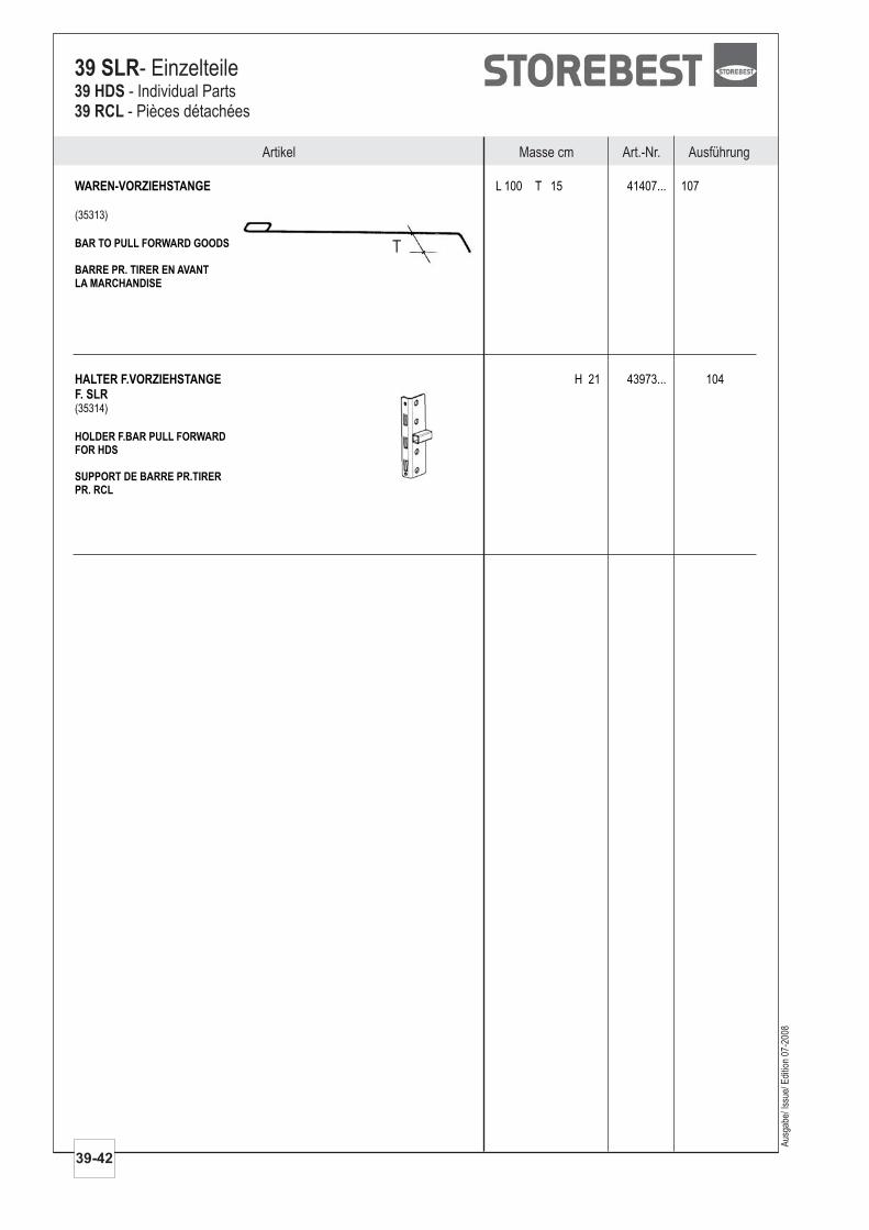
Artikel Masse cm Art.-Nr. Ausführung
39-42
39 SLR- Einzelteile39 HDS39 RCL
- Individual Parts- Pièces détachées
Aus
gabe
/ Iss
ue/ E
ditio
n 07
-200
8
WAREN-VORZIEHSTANGE L 100 T 15 41407... 107
(35313)
BAR TO PULL FORWARD GOODS
BARRE PR. TIRER EN AVANTLA MARCHANDISE
T
HALTER F.VORZIEHSTANGEF. SLR
H 21 43973... 104
(35314)
HOLDER F.BAR PULL FORWARDFOR HDS
SUPPORT DE BARRE PR.TIRERPR. RCL