stress analysis on transmission gears of a …ziraatdergi.akdeniz.edu.tr/_dinamik/144/283.pdf ·...
TRANSCRIPT
AKDENİZ ÜNİVERSİTESİ ZİRAAT FAKÜLTESİ DERGİSİ, 2008, 21(2), 155–160
155
STRESS ANALYSIS ON TRANSMISSION GEARS OF A ROTARY TILLER USING FINITE ELEMENT METHOD
Mehmet TOPAKCIa H. Kursat CELIK Deniz YILMAZ Ibrahim AKINCI Akdeniz University, Faculty of Agriculture, Department of Agricultural Machinery, Antalya, Turkey
Accepted 12 August 2008
Abstract Rotary tiller is one of the tillage tools which gets own motion from tractor power take off (PTO) and it had
been designed for blend to soil. Soil traffic is decreased to great extent with this tool by blending the soil. Using of rotary tiller is increasing nowadays in our country because of its many benefits. Rotary tiller construction has a gear box that changes motion direction with 90 degrees from tractor PTO, transmission gears for rotation velocity and a rotor shaft which placed as horizontal to soil for blending. There are cutter blades on rotor shaft for breaking into pieces and blend to soil. Especially, on cutter blade and transmission gears, deformations occur because of high vibration, pointless high power, impact effect of soil parts, design-manufacturing error and wrong using conditions. Especially for construction and transmission parts, stress distributions should be determined well for understand failure reasons. In this study, transmission gear train of a rotary tiller which was designed and manufactured by a local manufacturer was modeled as three-dimensional in a parametric design software and structural stress distributions on transmission gears were simulated using a finite element method software according to its operating condition. After evaluating of simulation results, stress distributions on gears show that gears working without failure according to yield stress of gear’s materials. Additionally, working safety coefficient of gears calculated by reference simulation results. Keywords: Rotary Tiller, Stress Analysis, Finite Elements Method
Toprak Frezesi İletim Dişlilerinde Sonlu Elemanlar Metodu ile Gerilme Analizi Özet
Hareketini traktör kuyruk milinden alan toprak frezesi, toprağı parçalayarak karıştıran ve tarla trafiğinin azaltılmasında önemli bir yere sahip olan toprak işleme aletlerinden biridir. Ülkemizde, birçok yararlı özelliklerinden dolayı kullanımı her geçen gün artmaktadır. Toprak frezesi, traktör kuyruk miline bağlanan bir şaft ile aldığı hareketi ve gücü, yapısında bulunan dişli kutusu aracılığı ile 90° değiştirerek, kesici bıçakların bağlandığı rotor miline iletir. Toprak frezesi ile çalışma sırasında; özellikle kesici bıçaklar ve iletim dişlileri üzerinde yüksek titreşimler, dengelenemeyen kuvvet dağılımları, toprak parçalarının etkisi, tasarım-imalat hataları ve yanlış kullanımdan kaynaklanan deformasyonlar ve zorlanmalar meydana gelir. Tasarım sırasında toprak frezesi konstrüksiyonunun ve iletim elemanlarının üzerine gelen kuvvet dağılımlarının belirlenmesi, hasarların önüne geçilmesi bakımından çok önemlidir. Bu çalışmada, yerel bir firma tarafından tasarımı ve imalatı gerçekleştirilmiş bir toprak frezesine ait hareket iletim dişlileri üç boyutlu-parametrik modellenmiş ve çalışma koşullarındaki mukavemet analizleri, sonlu elemanlar yöntemi kullanılarak simüle edilmiştir. Gerçekleştirilen simülasyon sonrası dişliler üzerindeki eşdeğer gerilme dağılımları gösterilmiştir. Dişliler imal edildikleri malzeme akma mukavemeti değerine göre değerlendirilmiş ve dişlilerin hasara uğramadan çalıştığı gösterilmiştir. Ek olarak, her bir dişlinin malzeme akma mukavemeti değeri esas alınarak, uygulanan kuvvet altında güvenli çalışma katsayıları belirlenmiştir. Anahtar Kelimeler: Toprak Frezesi, Gerilme Analizi, Sonlu Elemanlar Yöntemi
1. Introduction
a Corresponding author: M. Topakcı, e-mail: [email protected]
Rotary tiller is a tillage machine which is used in arable field and fruit garden
in agriculture. Rotary tiller has a huge capacity for cutting, mixing to topsoil and
Stress Analysis on Transmission Gears of a Rotary Tiller Using Finite Element Method
156
preparing the seedbed preparation directly. Additionally, a rotary tiller has more mixing capacity seven times than a plough (Ozmerzi, 2002).
The rotary tiller is attached to three point linkage system of a tractor and it is driven by the tractor PTO (Power Take Off). The motion direction is changed as 90 degrees from tractor PTO to second gear box by horizontal shaft. The rotor shaft gets its motion from second gear box.
Rotary tiller’s elements work under miscellaneous forces because of high vibration, pointless high power, impact effect of soil parts, design-manufacturing errors and wrong using conditions in tillage operation. Therefore, undesired stress distributions occur on its elements. If the elements cannot compensate to the operating forces, these elements become useless because of breaking or high deformation failure. Especially blades and transmission elements have to be durable against to operating forces. Predicting to stress distributions is so important for the designers and manufacturers to generate good working designs and products without failure. Machine manufacturers, which want to prevent for probable errors of their own machines, use materials, which have high safety coefficient, or they use high weight machine elements. Although these prevention methods can be safety, weight and cost of products rise.
Helping with developed technologies and design software which integrated in new generation computers, designs are getting easier and reliable. Designers can design own products in virtual screen and they can evaluate working condition of the products
by simulating techniques using the computers. Today three-dimensional (3D) modeling and finite elements method applications are getting so widespread in the industry. Many of 3D modeling and finite elements application samples can be seen on different engineering disciplines (Gunay, 1993).
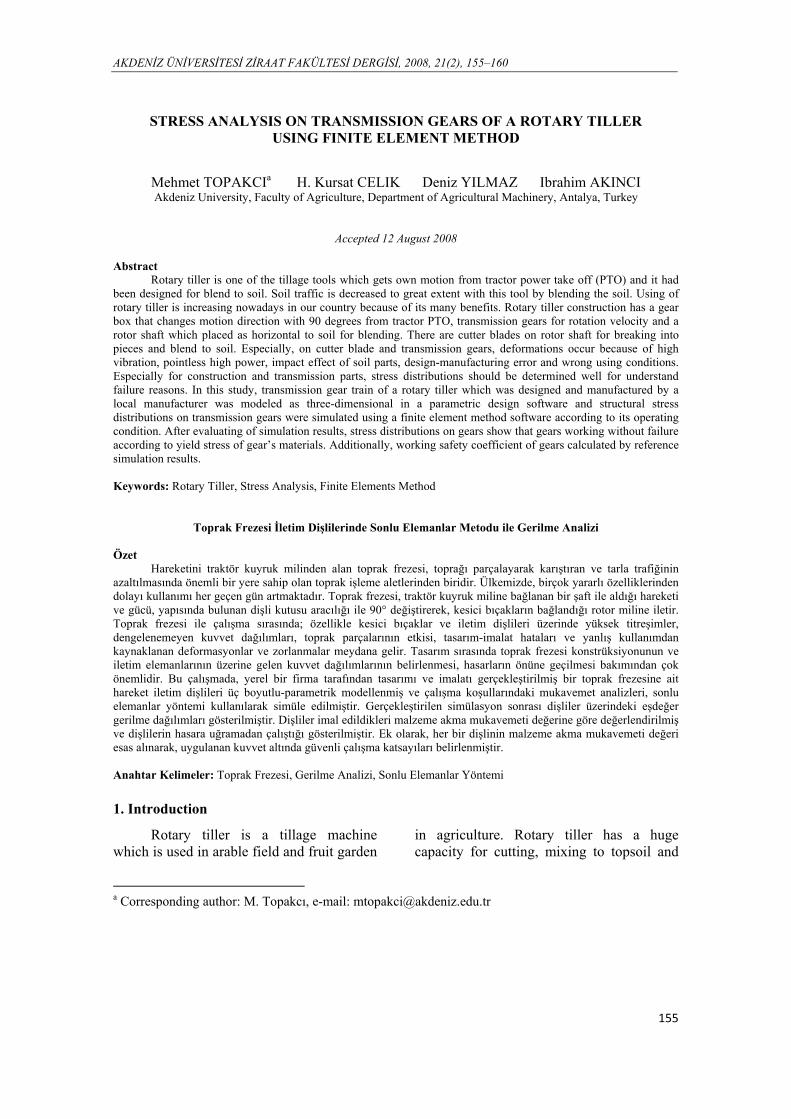
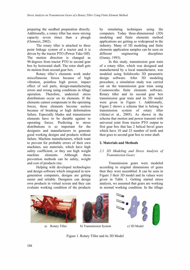
In this study, transmission gear train of a rotary tiller, which was designed and manufactured by a local manufacturer, was modeled using Solidworks 3D parametric design software. After 3D modeling procedure, a simulation study was carried out on the transmission gear train using Cosmosworks finite elements software. Rotary tiller and its second gear box transmission gear train and its 3D model were given in Figure 1. Additionally, Figure 2 shows a schema that is belong to transmission system of rotary tiller (Akinci et al., 2005). As shown in the schema that motion and power transmit with universal joint from tractor PTO output to first gear box that has 2 helical bevel gears which have 10 and 23 number of teeth and then goes to second gear box to rotor shaft.
2. Materials and Methods 2.1 3D Modeling and Stress Analysis of
Transmission Gears
Transmission gears were modeled according to original dimensions of gears then they were assembled. It can be seen in Figure 3 their 3D model and its values were given in Table 1. Getting started stress analysis, we assumed that gears are working in normal working condition. In the tillage
Figure 1. Rotary Tiller and its 3D Model
a) Rotary Tiller b) Transmission System c) 3D Model
M. TOPAKCI, H. K. CELIK, D. YILMAZ, I. AKINCI
157
Figure 2. Schema of Transmission System of Rotary Tiller
Figure 3. Assembled Gear Train
operation with rotary tiller, required tractor PTO power was taken as 49.5 kW and tractor PTO revolution was 540 min-1. According to tractor PTO power and transmission ratios, moments of gears have been accounted. Table 1. Values of Transmission Gears
Values of Transmission Gears GEAR I
GEARII
GEARIII
Module [mm] 6 6 6 Number of teeth [ - ] 31 43 38 Face width [mm] 38 38 38 Axel diameter [mm] 55 82 55 Moments [Nm] 373.00 263.56 292.40
In simulation, two analyses generated for each two gear pairs (Gear I-II and Gear II-III) on working condition. Analyses have been generated in 3D, static and linear assumptions in Cosmosworks finite elements software. Isotropic material properties were used in simulation and properties of gear’s material was given at Table 2 (Kutay, 2003). While assembling, it was noted that working gear’s tooth in contact, paired just at single contact condition with each others. Because, experiments show that maximum stresses and failures on gears occur on gear’s surface
Stress Analysis on Transmission Gears of a Rotary Tiller Using Finite Element Method
158
contact zone and tooth root on single contact condition (Curgul, 1993).
Table 2. Material Properties of Gears Material DIN C45 Elastic modulus [GPa] 211 Tensile strength [MPa] 700 Yield strength [MPa] 500 Poisson’s ratio [ - ] 0.30 Density [kg/m3] 7850 2.2 Stress Analysis Between on Gear I and
Gear II
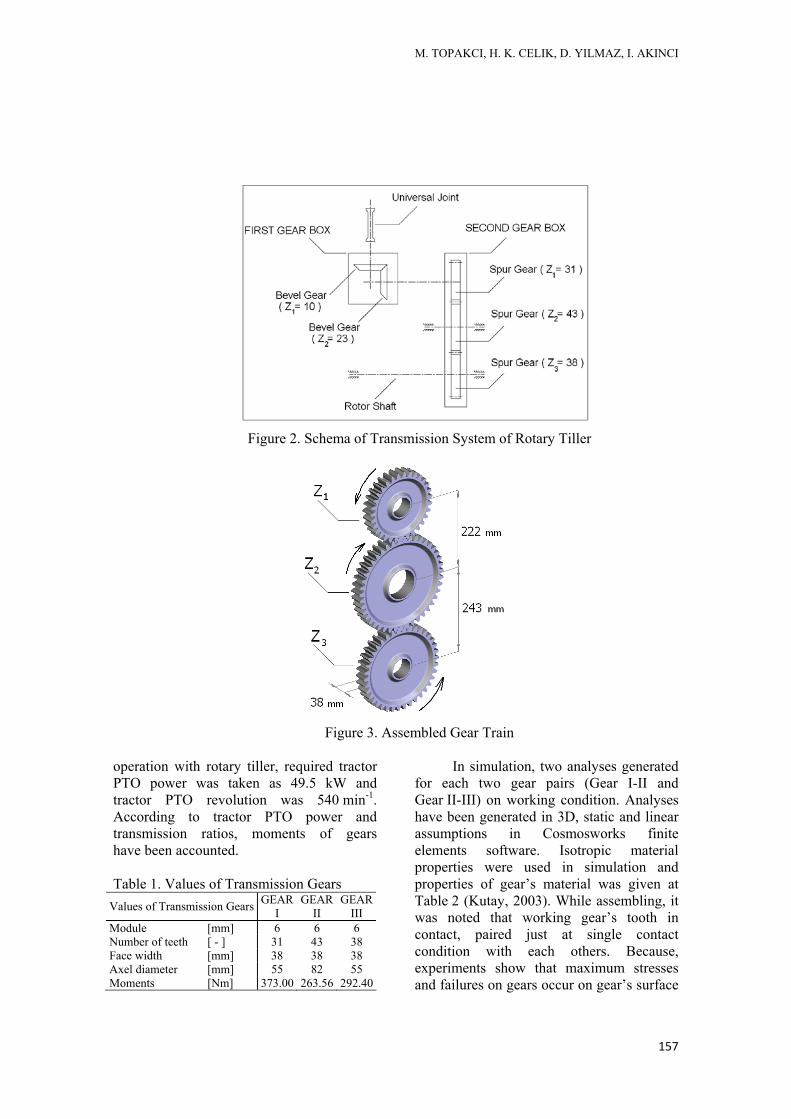
After assembling of Gear I and Gear II, boundary condition was applied. Gear II fixed from bearing of its shaft. Accounted moment value was applied at direction of rotation axis to Gear I and its mesh construction can be seen in Figure 4.
Cosmosworks meshing functions have been used to map the meshing. Higher-order (Second-order) parabolic solid tetrahedral element which has four corner nodes, six mid-side nodes, and six edges attached by meshing function for high quality mesh construction (CosmosWorks, 2006).
After meshing operation, 342160 total elements and 489339 total nodes obtained for meshed Gear I and Gear II in total.
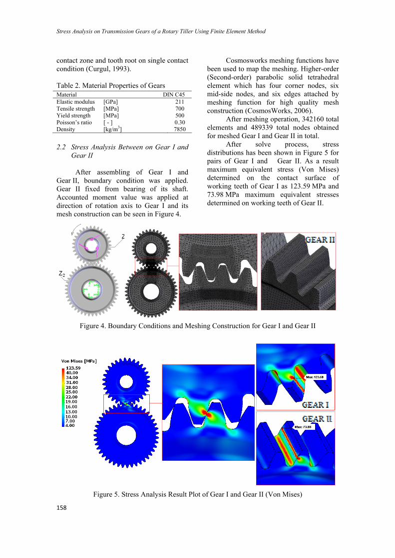
After solve process, stress distributions has been shown in Figure 5 for pairs of Gear I and Gear II. As a result maximum equivalent stress (Von Mises) determined on the contact surface of working teeth of Gear I as 123.59 MPa and 73.98 MPa maximum equivalent stresses determined on working teeth of Gear II.
Figure 4. Boundary Conditions and Meshing Construction for Gear I and Gear II
Figure 5. Stress Analysis Result Plot of Gear I and Gear II (Von Mises)
M. TOPAKCI, H. K. CELIK, D. YILMAZ, I. AKINCI
159
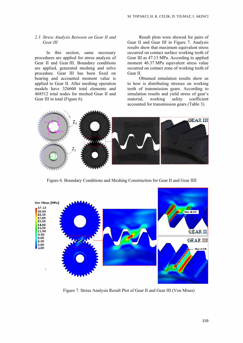
2.3 Stress Analysis Between on Gear II and Gear III
In this section, same necessary
procedures are applied for stress analysis of Gear II and Gear III. Boundary conditions are applied, generated meshing and solve procedure. Gear III has been fixed on bearing and accounted moment value is applied to Gear II. After meshing operation models have 326600 total elements and 468512 total nodes for meshed Gear II and Gear III in total (Figure 6).
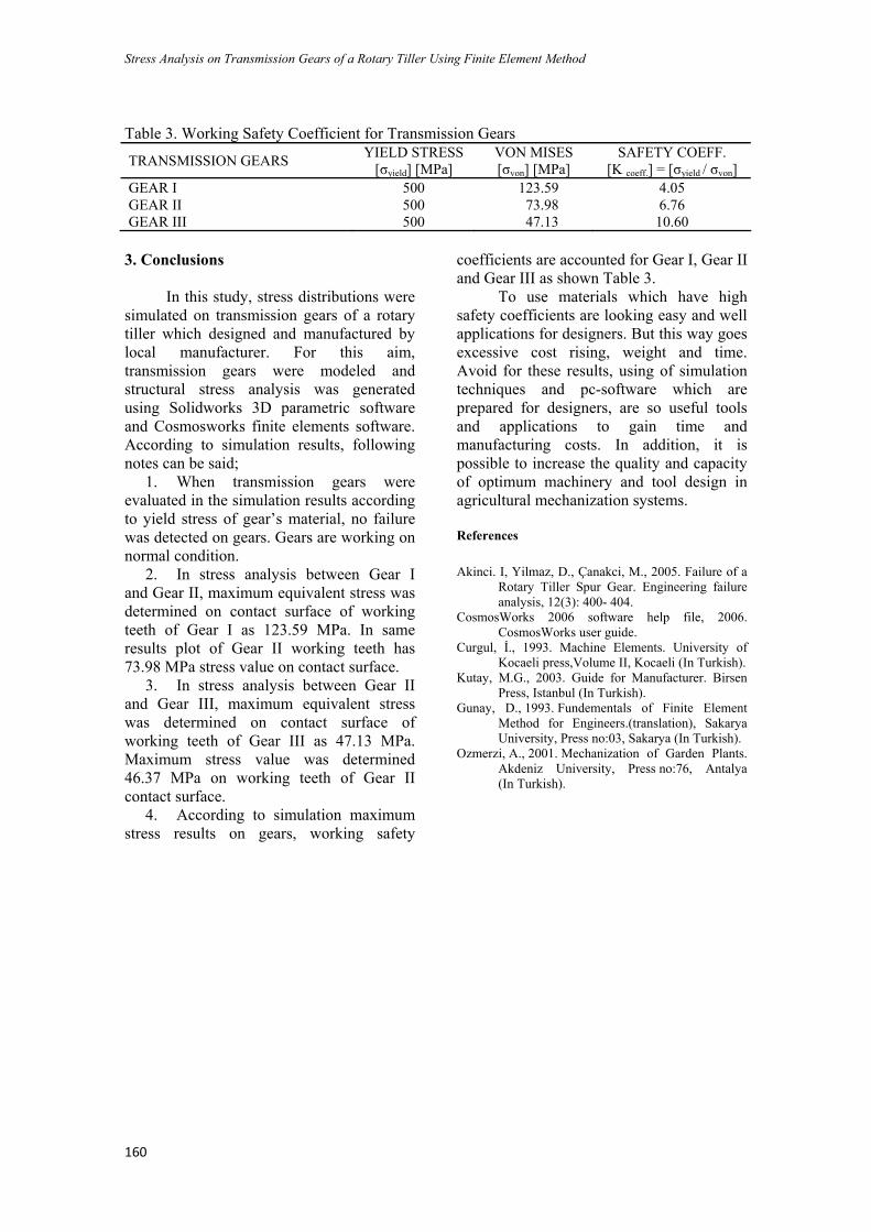
Result plots were showed for pairs of Gear II and Gear III in Figure 7. Analysis results show that maximum equivalent stress occurred on contact surface working teeth of Gear III as 47.13 MPa. According to applied moment 46.37 MPa equivalent stress value occurred on contact zone of working teeth of Gear II.
Obtained simulation results show us to how is distributing stresses on working teeth of transmission gears. According to simulation results and yield stress of gear’s material, working safety coefficient accounted for transmission gears (Table 3).
Figure 6. Boundary Conditions and Meshing Construction for Gear II and Gear IIII
Figure 7. Stress Analysis Result Plot of Gear II and Gear III (Von Mises)
Stress Analysis on Transmission Gears of a Rotary Tiller Using Finite Element Method
160
Table 3. Working Safety Coefficient for Transmission Gears
TRANSMISSION GEARS YIELD STRESS [σyield] [MPa]
VON MISES [σvon] [MPa]
SAFETY COEFF. [K coeff.] = [σyield / σvon]
GEAR I 500 123.59 4.05 GEAR II 500 73.98 6.76 GEAR III 500 47.13 10.60 3. Conclusions
In this study, stress distributions were simulated on transmission gears of a rotary tiller which designed and manufactured by local manufacturer. For this aim, transmission gears were modeled and structural stress analysis was generated using Solidworks 3D parametric software and Cosmosworks finite elements software. According to simulation results, following notes can be said;
1. When transmission gears were evaluated in the simulation results according to yield stress of gear’s material, no failure was detected on gears. Gears are working on normal condition.
2. In stress analysis between Gear I and Gear II, maximum equivalent stress was determined on contact surface of working teeth of Gear I as 123.59 MPa. In same results plot of Gear II working teeth has 73.98 MPa stress value on contact surface.
3. In stress analysis between Gear II and Gear III, maximum equivalent stress was determined on contact surface of working teeth of Gear III as 47.13 MPa. Maximum stress value was determined 46.37 MPa on working teeth of Gear II contact surface.
4. According to simulation maximum stress results on gears, working safety
coefficients are accounted for Gear I, Gear II and Gear III as shown Table 3.
To use materials which have high safety coefficients are looking easy and well applications for designers. But this way goes excessive cost rising, weight and time. Avoid for these results, using of simulation techniques and pc-software which are prepared for designers, are so useful tools and applications to gain time and manufacturing costs. In addition, it is possible to increase the quality and capacity of optimum machinery and tool design in agricultural mechanization systems. References Akinci. I, Yilmaz, D., Çanakci, M., 2005. Failure of a
Rotary Tiller Spur Gear. Engineering failure analysis, 12(3): 400- 404.
CosmosWorks 2006 software help file, 2006. CosmosWorks user guide.
Curgul, İ., 1993. Machine Elements. University of Kocaeli press,Volume II, Kocaeli (In Turkish).
Kutay, M.G., 2003. Guide for Manufacturer. Birsen Press, Istanbul (In Turkish).
Gunay, D., 1993. Fundementals of Finite Element Method for Engineers.(translation), Sakarya University, Press no:03, Sakarya (In Turkish).
Ozmerzi, A., 2001. Mechanization of Garden Plants. Akdeniz University, Press no:76, Antalya (In Turkish).