structural engineering stage 03 report
TRANSCRIPT

STRUCTURAL ENGINEERING STAGE 03 REPORT
KINGSTON COUNCIL –
KINGFISHER LEISURE CENTRE
STRUCTURAL ENGINEERING -
STAGE 03 REPORT
July 2020

STRUCTURAL ENGINEERING STAGE 03 REPORT
KINGSTON COUNCIL – KINGFISHER LEISURE CENTRE
STRUCTURAL ENGINEERING STAGE 03 REPORT
July 2020
Prepared for Royal Borough of Kingston upon Thames
Fairfield Road
Kingston Upon Thames
KT1 2PY
Prepared by Ridge and Partners LLP
Partnership House
Moorside Road
Winchester
Hampshire
SO23 7RX
Tel: 01962 834400
Contact Aftaab Deader
Senior Structural Engineer

STRUCTURAL ENGINEERING STAGE 03 REPORT
VERSION CONTROL
PROJECT NAME: Kingston Council – Kingfisher Leisure Centre
PROJECT NUMBER: 5012853
DOCUMENT REFERENCE: 5012853-RDG-XX-XX-DOC-S-9001
DOCUMENT STATUS: S3 – SUITABLE FOR REVIEW & COMMENT
REV DATE DESCRIPTION AUTHOR CSE ICSE
- 6 JULY
2020
INITIAL ISSUE M A Deader
MEng(Hons) CEng MICE
M A Deader
MEng(Hons) CEng MICE
J McCulloch
BEng(Hons) MSc CEng MICE
A 24 JULY
2020
REVISED TO SUIT CLIENT
COMMENTS
M A Deader
MEng(Hons) CEng MICE
M A Deader
MEng(Hons) CEng MICE
J McCulloch
BEng(Hons) MSc CEng MICE
STRUCTURAL ENGINEERING STAGE 03 REPORT
CONTENTS
EXECUTIVE SUMMARY 1
1. INTRODUCTION 2
1.1. Client brief/ requirements 2
1.2. Existing Structure 2
2. ENVISAGED SEQUENCE OF WORKS 4
2.1. Separation of roof structures 4
2.2. Temporary Stability of swimming pool roof 6
2.3. Long-term temporary works 9
2.4. Installation of the new roof 10
3. PROPOSED ROOF STRUCTURE 12
3.1. Design Philosophy 12
4. DESIGN DEVELOPMENT 13
4.1. Information required 13
STRUCTURAL ENGINEERING STAGE 03 REPORT
Project: 5012853 1
EXECUTIVE SUMMARY
Ridge and Partners LLP have carried out a visual inspection on a space-frame structure which forms the roof
of the swimming pool at Kingfisher Leisure Centre in Kingston, London. This report relates to the replacement
strategy of the roof which is severely corroded and in need of replacement.
The steel space-frame structure has an overall column free area over 1000m² and is supported on central
columns on each edge and corner columns which are offset from the roof corners by circa 2m. The top chords
of the structure consist of square hollow sections (SHS) tied with steel tied rods to the bottom chords which
are typically circular hollow sections (CHS).
At the connection and node intersections there is significant corrosion of the ‘knuckle’ joints and some areas
this is considered at risk of immediate collapse. After several further investigations it has been proposed that
it would be more economical and potentially less complicated to replace the swimming pool roof rather than
attempting to refurbish the connections.
In the short- term the client wishes to open up part of the building and this can be done by separating the ‘dry
side’ area from the swimming pool roof by re-routing of ductwork in that location, weatherproofing the
junction between the two areas and providing adequate protection for the occupants of the building from any
potential collapse of the swimming pool roof.
The existing scaffolding in the swimming pool forms a crash deck and has not been completed. It is proposed
that a crash deck will be required for the remaining roof structure which can be formed by additional
scaffolding or proprietary propping which may be quicker to install, thereby reducing the safety risk to
occupants and workers. This will also create a working platform for future dismantling of the existing roof.
The next stage involves creating a series of trusses which will span over the roof and connect into the existing
roof to allow for sequential removal of the space frame members from below. Once the existing space frame
has been completely removed the trusses can be lowered into the position of the old roof structure to form
the permanent works. The new roof structure will connect into and utilise the existing columns. The roof can
then be made weathertight with any necessary roof plant installed and the temporary propping internally can
be removed.
Further development of the proposals will require engaging with contractors and specialist suppliers to enable
a construction sequence to be established as well as potential timescales for completion.

STRUCTURAL ENGINEERING STAGE 03 REPORT
Project: 5012853 2
1. INTRODUCTION
1.1. Client brief/ requirements Royal Borough of Kingston have approached Ridge and Partners LLP to provide a strategy for re-opening of
the ‘dry side’ of Kingfisher leisure centre. In the context of this report the ‘dry side’ refers to the part of the
building to the North of the swimming pool area.
It was noted in the previous investigation of the structure that the roof purlins from the dry side are connected
to the space frame structure of the swimming pool. Any proposal would need to consider a way of separating
the 2 areas to allow waterproofing of the dry side and temporary protection in case of partial or complete
collapse of the swimming pool roof.
Subsequent to this, a safe method of removal of the existing roof structure needs to be determined, taking
into consideration safety of workers and the public and a solution which would facilitate the removal of the
temporary birdcage scaffold.
1.2. Existing Structure The swimming pool roof comprises a space frame structure formed of SHS and CHS sections with tie rods
connecting the top and bottom chords. The wall thickness of the CHS and SHS sections is unknown, however
some assumptions have been made and a finite element model of the structure has been constructed.
The swimming pool side walls consist of reinforced concrete which is assumed to be ground bearing but may
be piled. The walkways around the edge of the swimming pool are suspended in-situ RC concrete slabs
supported off assumed concrete beams and columns. The steel superstructure is then assumed to be fixed
down to the concrete columns below ground.
It is not clear if the concrete substructure exists only in the swimming pool area or the rest of the building as
well. It is clearly visible on the West side of the building as the plant room forms part of the under-croft area
below the walkway around the swimming pool edge (see indicative section below).
Figure 1 - Typical section through west side of swimming pool area (not to scale)
The ‘dry area’ is assumed to be a steel-framed structure and the columns between the dry area and the
swimming pool support both structures. The first floor slab soffit is visible from the underside of the balcony
STRUCTURAL ENGINEERING STAGE 03 REPORT
Project: 5012853 3
and appears to be an in-situ RC concrete slab with either concrete downstand beams or steel beams encased
in concrete. The construction of these cannot be verified at this stage.
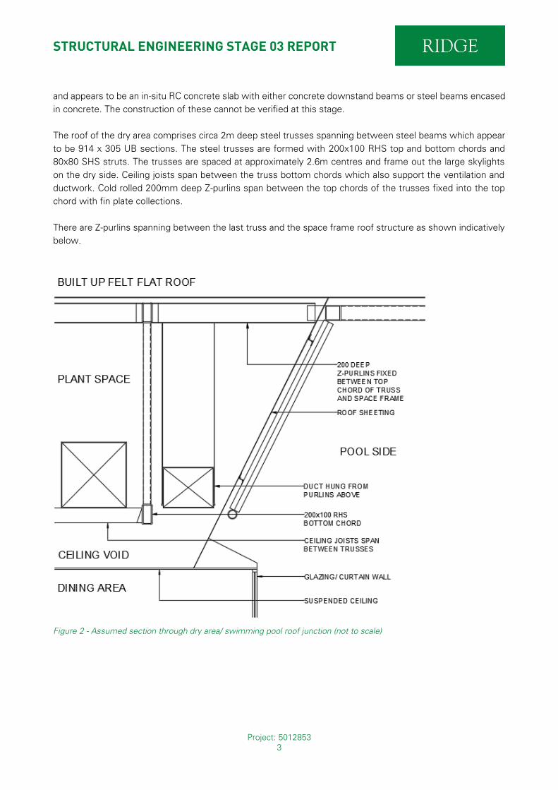
The roof of the dry area comprises circa 2m deep steel trusses spanning between steel beams which appear
to be 914 x 305 UB sections. The steel trusses are formed with 200x100 RHS top and bottom chords and
80x80 SHS struts. The trusses are spaced at approximately 2.6m centres and frame out the large skylights
on the dry side. Ceiling joists span between the truss bottom chords which also support the ventilation and
ductwork. Cold rolled 200mm deep Z-purlins span between the top chords of the trusses fixed into the top
chord with fin plate collections.
There are Z-purlins spanning between the last truss and the space frame roof structure as shown indicatively
below.
Figure 2 - Assumed section through dry area/ swimming pool roof junction (not to scale)

STRUCTURAL ENGINEERING STAGE 03 REPORT
Project: 5012853 4
2. ENVISAGED SEQUENCE OF WORKS
The works required to stabilise the roof and separate the dry side from the swimming pool need to be
undertaken in several stages. These are as follows:
1. Isolation of the dry side roof from the swimming pool roof by providing support for the roof Z-purlins
from the dry side. The existing duct which is hung from the underside of the purlins would need to
be relocated.
2. Weatherproofing the dry side roof from the pool side roof, including providing impact protection for
the glazing/ curtain walling between the 2 areas.
3. Temporary stability of the swimming pool roof to enable construction workers to safely work within
the swimming pool area for erection of long-term temporary works related to the replacement of the
roof structure
4. Removal of the existing roof structure and installation of the new roof.
Each of the items above will be addressed in the following sections.
2.1. Separation of roof structures The cold rolled purlins which are fixed between the trusses and space frame structure of the roof need to be
separated from the pool side. This can be done by fixing a bracket to the underside of the Z-purlin or a member
fixed down to the bottom chord of the adjacent truss. However, this would require the duct to be raised up
to prevent a clash with the new diagonal member.
A second option which would potentially be simpler and cheaper would be to relocate the duct and then
remove the purlin at the truss location. The face of the truss would then allow for fixing of cold rolled purlins
or sheet material to enable weatherproofing. A cursory inspection of the truss area suggests that there may
be enough space to move the duct further in-board, away from the swimming pool roof – but it would need
to be verified by the M&E consultants following the validation exercise which was recently carried out. Initial
discussions suggest this may be feasible.
Access to the space will need to be carefully considered. A timber joist ‘platform’ above the proposed stud
wall can be installed from underneath the area by removal of ceiling finishes. An access door can then be
provided between the truss and the separation line, construction workers can then weatherproof that area
using the timber platform for access and then once complete go back through the access hatch door into the
plant space. Then any minor works required to finish off/ seal can be done from the dry side roof.
Weatherproofing of the roof should be done in consultation with a specialist and is outside the scope of this
report although it is expected that this will consist of a single ply fully adhered membrane or built-up felt (to
be confirmed after specialist consultation). The water would need to be re-directed to suitable outlets at the
ends of the roof (see fig. 3).

STRUCTURAL ENGINEERING STAGE 03 REPORT
Project: 5012853 5
Figure 3 - Google maps view of building showing separation line in dashed red line
The glazed screen/ curtain walling between the swimming pool and dry side must be protected by a barrier/
wall which sufficiently robust in case of accidental impact from a member falling from height. Due to the
position of the proposed separation wall it is not expected that it will be subject to a direct impact from any
falling members but only a glancing blow.
Therefore, in this instance it is considered that it will be sufficient to provide an 18mm plywood sheathed stud
wall and joists which are restrained against movement due to a new angle fixed to the underside of the
adjacent truss. The stud wall can also be resin fixed into the concrete balcony below, providing further
resistance against movement. A final protective measure would be to provide hoarding on the inside face of
the glazing (see fig. 4).

STRUCTURAL ENGINEERING STAGE 03 REPORT
Project: 5012853 6
Figure 4 - Proposal for weatherproofing dry side (Final Details TBC)
2.2. Temporary Stability of swimming pool roof Currently there is a birdcage scaffold adjacent to the balcony at the entrance to the swimming pool, coming
from the dry area. This has been installed as a temporary ‘crash deck’ solution in case of full or partial collapse
of the roof structure. The connection nodes in this area were identified as being particularly badly corroded
and at risk of severance therefore the scaffold structure was installed as a temporary protection measure.
It is understood that the client wishes to remove this due to the ongoing hire costs. However, we advise that
the scaffold remains in place otherwise it would need to be replaced with another form of propping which
could potentially be more expensive. However, it is also recommended that the scaffold structure is extended
further into the building to create a larger crash deck. An assessment could be made for the worst-case areas
and birdcage scaffold areas located in those locations only if cost is to be minimised.
The scaffold will take time to erect and there is an inherent risk for scaffold workers whilst constructing the
crash decks. However, this will allow for safe access for future workers, inspectors and surveyors, especially
if passages are created within the scaffold structure to allow visitors to walk safely through the birdcage
STRUCTURAL ENGINEERING STAGE 03 REPORT
Project: 5012853 7
constructions. The scaffold designer needs to take into consideration the possible weight of the structure if it
did collapse and we can also liaise with and advise on these loads.
The creation of the crash deck would also enable the second phase of works to begin which would involve
supporting the roof structure from above e.g. hanging the top chord members from a temporary structure
over the roof whilst also allowing for safe access for workers to de-construct the roof structure from the
underside. The downside of erecting a scaffold over the entire floor area would be time and speed and the
longer the workers spend inside the swimming pool the greater the risk they are exposed to.
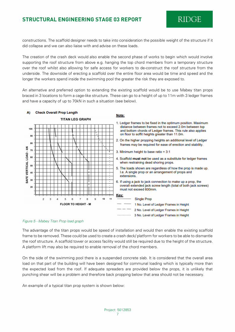
An alternative and preferred option to extending the existing scaffold would be to use Mabey titan props
braced in 3 locations to form a cage-like structure. These can go to a height of up to 11m with 3 ledger frames
and have a capacity of up to 70kN in such a situation (see below).
Figure 5 - Mabey Titan Prop load graph
The advantage of the titan props would be speed of installation and would then enable the existing scaffold
frame to be removed. These could be used to create a crash deck/ platform for workers to be able to dismantle
the roof structure. A scaffold tower or access facility would still be required due to the height of the structure.
A platform lift may also be required to enable removal of the chord members.
On the side of the swimming pool there is a suspended concrete slab. It is considered that the overall area
load on that part of the building will have been designed for communal loading which is typically more than
the expected load from the roof. If adequate spreaders are provided below the props, it is unlikely that
punching shear will be a problem and therefore back propping below that area should not be necessary.
An example of a typical titan prop system is shown below:

STRUCTURAL ENGINEERING STAGE 03 REPORT
Project: 5012853 8
Figure 6 - Titan Propping system with mid-height ledger frames (image courtesy: Mabey Hire)
It is important that there are temporary stability measures in place especially as the fabrication of the steel
trusses for the new roof could be on a long lead-in time.
The load takedown of the structure is as follows (estimated):
Self-weight of roof = 729kN
Dead load of finishes and cladding = 557kN
Services = 348kN (conservative)
Imposed Loads = 835kN
Total Load = 2469kN
Equivalent area load = 2469 / (34m x 36m) = 2.02kN/m² (Say 2.00kN/m² as loads are conservative).
Each node in the bottom chord is spaced at 2.8m c/c therefore the expected load per node = 2.00 x 2.8 x 2.8
/2 = 7.8kN. However, the spacing of the props may need to be reduced to ensure the top decking can span
the distance between props. Typically, the propping supplier will provide the props, ledger frames and primary
secondary beams at the top of the props for hire but the plywood decking would need to be bought outright
by the client because it is bespoke on each project. Access stairs and/ or a lifting platform may also be required.
It is considered that if the crash deck is located close the underside of the bottom chord (circa 150mm below)
then the acceleration of the roof downwards due to gravity will be negligible and the impact force will be equal
to the force through each node.
To enable the final design of the propping (and the temporary support structure over the top of the building),
a full measured survey of the building will be required due to the complexity of the swimming pool floor and
different levels/ steps. This is a service that Ridge can provide for an agreed fee.

STRUCTURAL ENGINEERING STAGE 03 REPORT
Project: 5012853 9
2.3. Long-term temporary works In the longer term, to enable eventual replacement of the roof structure, it is proposed to create a series of
structural frames to span over the top of the existing roof from which the existing roof structure could be
‘hung’ using tensile cables. The roof finishes/ sheeting would need to be penetrated in places to allow the
tensile cables to wrap around the top chord members which could be done simply by drilling holes through
the top sheeting. This would however require workers to walk on top of the roof, therefore it is important that
the crash deck is in place for this to occur.
The tensile cables will need to be fixed to lugs on the underside of the trusses using swaged fixings. It is
proposed to fix the tensile cables to a clamped fixed to the top chord of the roof with a lug on top. This will
consist of 2 plates bolted together with a neoprene/ rubber gasket in between to prevent the lug from sliding.
The tensile cables are expected to be 8-10mm thick stainless steel or galvanised cables and will require a
turnbuckle for pre-tensioning.
The structure which will span over the top of the existing roof can be in the form prefabricated steel girder
trusses which could subsequently be used as part of the permanent works once the old roof structure has
been fully removed (see image below). This will minimise wastage of materials and reduce time delays due
to any steel fabrication which may be subsequently required. It is proposed to make the support frame 4m
longer than the existing structure lengthways and 1m higher to clear the top of the existing roof lights (TBC).
Figure 7 - Proposed steel frame spanning over the top of the existing structure (existing columns and walls not shown)
STRUCTURAL ENGINEERING STAGE 03 REPORT
Project: 5012853 10
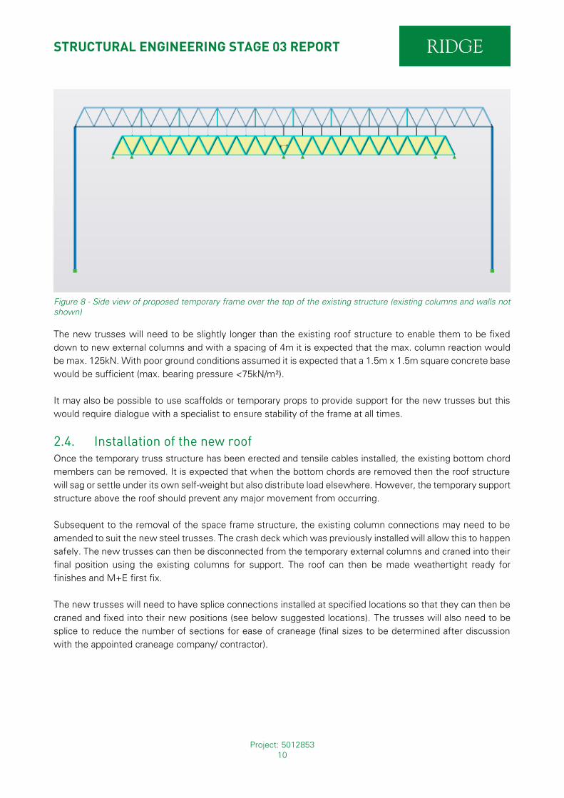
Figure 8 - Side view of proposed temporary frame over the top of the existing structure (existing columns and walls not shown)
The new trusses will need to be slightly longer than the existing roof structure to enable them to be fixed
down to new external columns and with a spacing of 4m it is expected that the max. column reaction would
be max. 125kN. With poor ground conditions assumed it is expected that a 1.5m x 1.5m square concrete base
would be sufficient (max. bearing pressure <75kN/m²).
It may also be possible to use scaffolds or temporary props to provide support for the new trusses but this
would require dialogue with a specialist to ensure stability of the frame at all times.
2.4. Installation of the new roof Once the temporary truss structure has been erected and tensile cables installed, the existing bottom chord
members can be removed. It is expected that when the bottom chords are removed then the roof structure
will sag or settle under its own self-weight but also distribute load elsewhere. However, the temporary support
structure above the roof should prevent any major movement from occurring.
Subsequent to the removal of the space frame structure, the existing column connections may need to be
amended to suit the new steel trusses. The crash deck which was previously installed will allow this to happen
safely. The new trusses can then be disconnected from the temporary external columns and craned into their
final position using the existing columns for support. The roof can then be made weathertight ready for
finishes and M+E first fix.
The new trusses will need to have splice connections installed at specified locations so that they can then be
craned and fixed into their new positions (see below suggested locations). The trusses will also need to be
splice to reduce the number of sections for ease of craneage (final sizes to be determined after discussion
with the appointed craneage company/ contractor).

STRUCTURAL ENGINEERING STAGE 03 REPORT
Project: 5012853 11
Figure 9 - Suggested splice locations (shown as dashed red line)

STRUCTURAL ENGINEERING STAGE 03 REPORT
Project: 5012853 12
3. PROPOSED ROOF STRUCTURE
3.1. Design Philosophy The existing roof structure was analysed to determine the existing column loads and the proposed structure
has been designed to emulate that as far as possible whilst enabling easier and quicker installation. The new
roof structure distributes the load to the existing columns in a similar way by using primary and secondary
trusses which means that the client does not need to replace the existing columns.
Furthermore, the trusses can be pre-fabricated in sections and craned into position quickly, whereas the space
frame structure requires significant temporary propping and bespoke connection details for the nodes. This
increases the costs for the steel fabricator and labour costs associated with time spent on site.
Finally, the new roof structure should be easier to maintain and externally the roof profile will be identical so
that there will be no subsequent planning issues. A screenshot of the proposed roof structure is shown below:
Figure 10 – Proposed final roof structure

STRUCTURAL ENGINEERING STAGE 03 REPORT
Project: 5012853 13
4. DESIGN DEVELOPMENT
4.1. Information required In order to develop the above scheme and strategy further, dialogue and discussion will be required with the
following disciplines/ specialists (note this list is not exhaustive):
• Main Contractor
• Propping supplier
• Steel fabricator
• Tensile cable manufacturer
The main contractor will need to liaise with sub-contractors and suppliers to determine a construction
programme based on the above proposals. They will also need to determine the craneage and access
requirements, taking into consideration public safety and maximum reach of the cranes. We are able to provide
an indicative programme to advise overall timescales for the project.
It is expected that the contract will be design and build with Ridge structures novated across to the
contractor’s design team or potentially a 2-stage tender with early contractor input and novation of Ridge
structural team at the 2nd stage. This would help to reduce potential conflicts at a later stage as the contractor
would be involved with design input at an early stage.
For the final install it is envisaged that at least 2 cranes will be required to enable lowering of the new roof
structure into place. As there are 7 main trusses which need to be installed, it is expected that they could be
lowered in pairs and they would remain tied to each other via secondary truss members. These would act to
restrain the 2 trusses. However, it is likely that the trusses will need to be lowered in sections and therefore
splice connections will be required at the locations where the segments are to be separated.
The exact dimensions of the roof will require a measured survey (usually instructed by the appointed steel
fabricator) to ensure that the new roof structure will be able to fit within the existing size constraints.
A measured survey of the existing structure will be required to ensure that the proposed temporary columns
can be positioned appropriately without causing a clash with building elements. This is particularly important
in the plant area to the West of the leisure centre where the temporary posts will need to penetrate through
the roof of the plant area and be fixed down to the floor of the plant room. Extending the trusses over the top
of this area would be uneconomic and unfeasible due to the size of the trusses required.
Trial pits or window samples will need to be taken around the edges of the swimming pool building to
determine the ground conditions which will enable final design of the foundations for the temporary columns.
We have a Geo-Environmental team within Ridge and can provide a fee quote for this service if required. Our
current cost estimates are based on assumptions of the ground conditions which will need to be verified at
the detailed design stage.