structural intelligence in flexible materials
TRANSCRIPT

CHAPTER 3STRUCTURAL INTELLIGENCE IN FLEXIBLE MATERIALS
Edward Allen, John Ochsendorf, and Mark West
Experiments in fabric-cast structures at the Centre for Architectural Structures and Technology (CAST) Winnipeg, Canada, 2012
WEST (Fabric Formwork Book) PRINT.indd 59 06/09/2016 15:41
Taylor & Francis: Not for Distribution

The natural world is filled with lessons in structural design. The strength of a doubly curved eggshell, the bending resistance of folded leaves, and the shape of cantilevered tree branches, are all instructive for designers as models for how to shape materials into elegant and efficient structural forms. Fabric-formed concrete elements have the potential to explore and capitalize on many of the same principles that enable structures in nature, due to the inherent structural “intelligence” of the mould’s flexible membrane. This chapter describes basic concepts of structural form, identifies inspirational precedents, and suggests areas for future exploration. The organic shaping of structures has been explored at length by others, in particular, D’Arcy Thompson (Thompson 1917) On Growth and Form and Frei Otto’s work on Finding Form (Otto and Rasch 1996). Two fundamental concepts are useful for the fabric formwork designer: funicular forms and force flow in solids. Both have been used by fabric formwork designers and both offer a powerful starting point for the future of more efficient and beautiful concrete structures.
Funicular formsThe term funicular, as it is used here, means “tension-only” or “compression-only” for a given loading. This is typically considered as the shape taken by a hanging chain for a given set of loads. Because flexible materials such as chains, ropes, and textiles offer no resistance in bending or compression, they can only form funicular structures that most efficiently follow the flow of tension forces. The most efficient way to resist a force is through axial tension, and the second most efficient mode of structural resistance is axial compression. Bending, the method of resistance used in frame structures, is relatively inefficient, at least in terms of the amount of material required for the structure. The relative virtues of different structural systems and geometries, and the choice of one system over another, involve multiple factors, but in terms of pure material consumption the answer is clear – funicular forms are extraordinarily efficient. A key symmetry in nature is the mirrored, inverse, relationship of tension and compression: if a flexible hanging chain (a funicular tension structure) has each of its links welded together, and is then flipped upside-down (inverted), it will stand as a funicular compression arch. The same strategy can be deployed in three dimensions using a hanging sheet of fabric loaded with a thin layer of wet concrete that is allowed to harden (see Chapter 11). Once inverted, the hard concrete acts as a funicular compression vault supporting its self-weight. This makes an architectural structure whose spatial surface is the shape of its own structural resistance to gravity. The earliest example of this kind of form-finding for an ideal arch in compression can be traced to the English scientist Robert Hooke (1635–1703) who, in 1676, first articulated this symmetry: “Ut pendet continuum flexile, sic stabit contiguum rigidum inversum” (“As hangs the flexible line, so but inverted will stand the rigid arch”) (Heyman 1997). The form of the ideal arch depends on the applied loading. For a chain of constant weight per unit length, the shape of a hanging chain acting under self-weight is a catenary (Figure 3.1). But if the load is uniformly distributed horizontally (as in a suspension bridge), the ideal arch would take the form of a parabola, which is slightly different. The chain or cable assumes different geometries according to the loading. Thus, even a simple two-dimensional arch has infinite possible forms that act in pure compression, depending on the distribution of weight and the rise of the arch. A simple experiment with string and small weights can be used to explore the families of funicular forms that are possible. The flexible string will immediately solve the structural form problem for any loading pattern by adjusting its shape accordingly. To continue the analogy with Hooke’s hanging chain, a three-dimensional web of hanging chains, technically called a cable net, can describe a variety of dome shapes. This is essentially how Robert Hooke envisioned the primary masonry dome of St Paul’s Cathedral in London in his collaboration with architect Christopher Wren (1632–1723) – a cubico-parabolical conoid form which is the ideal form of a compressive dome with zero hoop
40 Fabric Formwork
Figure 3.1 Hooke’s hanging chain and the inverted rigid catenary arch, as depicted by Poleni (1748)
WEST (Fabric Formwork Book) PRINT.indd 60 06/09/2016 15:41
Taylor & Francis: Not for Distribution

forces (Heyman 1998). However, many more forms are possible for shells. Three-dimensional funicular systems are considerably more complex than two-dimensional arches because of the multiple load paths that are possible through a three-dimensional surface. Unlike a two-dimensional arch, a three-dimensional shell can carry a wide range of different loadings, through membrane behavior, without introducing bending. When flat fabric sheets are used to form three-dimensional funicular structures, the geometric possibilities become even more interesting. The warp and weft threads of a woven fabric form a kind of a cable net. By the shearing action of the warp and weft threads, a flat woven sheet can, to a certain extent, produce smooth double curvatures without buckling (see Figure 4.2, p. 53). However, deeper curvatures will start to produce buckles in the sheet. Concentrated tension forces in the sheet will tend to produce pull-buckles along the principal lines of force, as seen in Figure 3.2. (For more on pull-buckles see Chapter 4, pp. 60–3.) These buckled shapes have the potential to create structurally useful corrugations (see Chapter 11: Hanging sheet moulds, pp. 220–3). Such flat-sheet behaviors introduce a new vocabulary for thin-shell structures, waiting to be explored by architects, engineers, and builders. Engineer Heinz Isler (1926–2009) derived such forms from hanging physical models to provide stiffening corrugations near the edges of his compressive shells in concrete (Chilton 2000). Structural designers can take inspiration from any number of sources, but Robert Hooke’s powerful axiom provides a clear path forward. The tensile capacity of the formwork membrane and the compressive capacity of concrete perfectly complement each other, while the very act of casting provides the geometric inversion that can “flip” a convex tension-net geometry into a concave compression shell geometry. By minimizing bending forces, designers can build more efficiently and can make better use of limited resources. By understanding and exploring the infinite possibilities for even highly constrained design problems, designers can continue to discover new structural forms for centuries to come.
Flow of forces in solidsLeaving the discussion of funicular shells, we turn our attention to the shaping of structural members, such as columns, beams, and walls. Concealed within the volume of each loadbearing piece of material – concrete, wood, steel, glass, stone, brick, even the soil beneath the foundations – is an orderly and predictable pattern of pushes and pulls. Each pattern is established by the forces that are applied to the piece of material and the shape of the piece itself, in such a way that the piece does its share of the work of supporting the bridge or building with minimal work. When the applied forces change, due to a change in the direction or intensity of the wind, or a relocation of the loads on the building floor or bridge deck, all the patterns of pushing and pulling change instantly to
41Structural Intelligence in Flexible Materials
Figure 3.2 Flat-sheet funicular vault forms: a) pull-buckles form corrugated ribs radiating from a shell’s corner supports; b) buckles form corrugated ribs radiating from the shell’s primary supports (see Chapter 11: Hanging sheet moulds, p. 220, and Figures 11.37–40, pp. 220–3, in particular)
WEST (Fabric Formwork Book) PRINT.indd 61 06/09/2016 15:41
Taylor & Francis: Not for Distribution
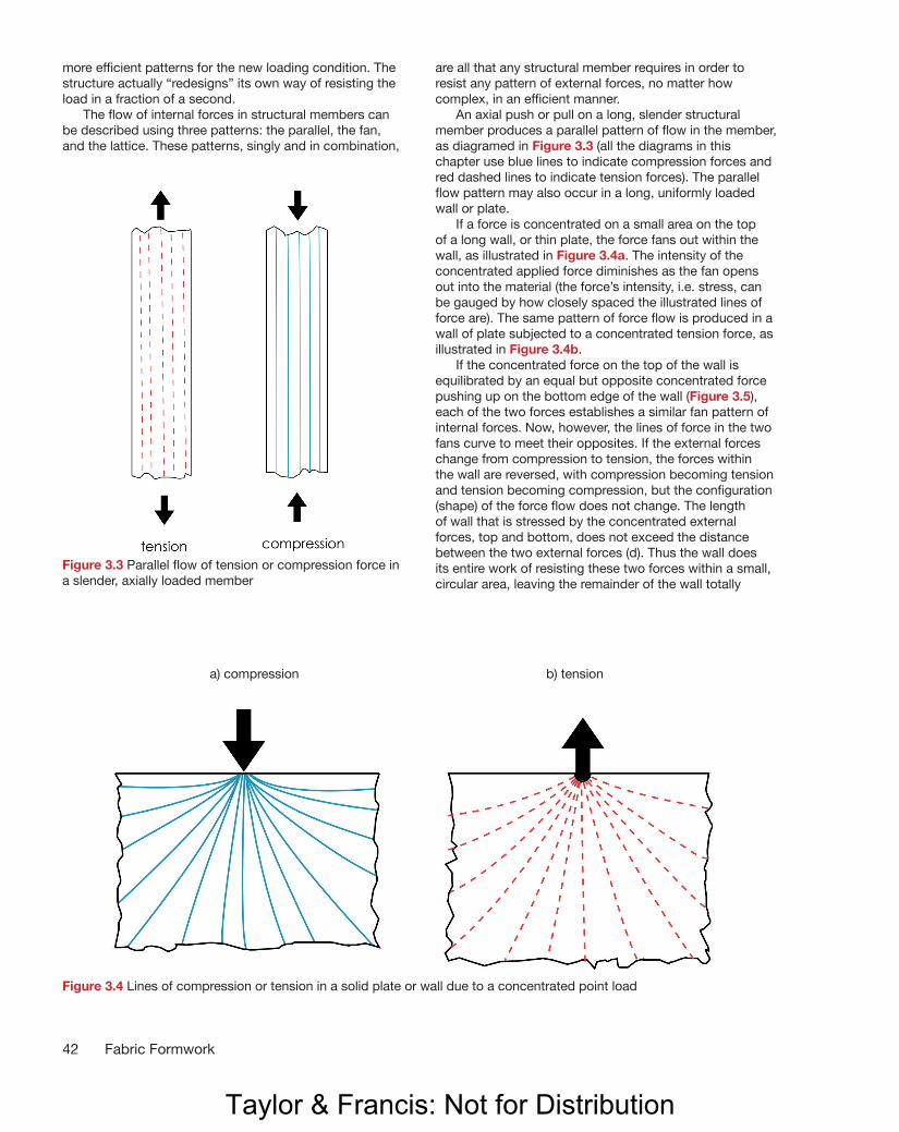
more efficient patterns for the new loading condition. The structure actually “redesigns” its own way of resisting the load in a fraction of a second. The flow of internal forces in structural members can be described using three patterns: the parallel, the fan, and the lattice. These patterns, singly and in combination,
are all that any structural member requires in order to resist any pattern of external forces, no matter how complex, in an efficient manner. An axial push or pull on a long, slender structural member produces a parallel pattern of flow in the member, as diagramed in Figure 3.3 (all the diagrams in this chapter use blue lines to indicate compression forces and red dashed lines to indicate tension forces). The parallel flow pattern may also occur in a long, uniformly loaded wall or plate. If a force is concentrated on a small area on the top of a long wall, or thin plate, the force fans out within the wall, as illustrated in Figure 3.4a. The intensity of the concentrated applied force diminishes as the fan opens out into the material (the force’s intensity, i.e. stress, can be gauged by how closely spaced the illustrated lines of force are). The same pattern of force flow is produced in a wall of plate subjected to a concentrated tension force, as illustrated in Figure 3.4b. If the concentrated force on the top of the wall is equilibrated by an equal but opposite concentrated force pushing up on the bottom edge of the wall (Figure 3.5), each of the two forces establishes a similar fan pattern of internal forces. Now, however, the lines of force in the two fans curve to meet their opposites. If the external forces change from compression to tension, the forces within the wall are reversed, with compression becoming tension and tension becoming compression, but the configuration (shape) of the force flow does not change. The length of wall that is stressed by the concentrated external forces, top and bottom, does not exceed the distance between the two external forces (d). Thus the wall does its entire work of resisting these two forces within a small, circular area, leaving the remainder of the wall totally
42 Fabric Formwork
Figure 3.4 Lines of compression or tension in a solid plate or wall due to a concentrated point load
a) compression b) tension
Figure 3.3 Parallel flow of tension or compression force in a slender, axially loaded member
WEST (Fabric Formwork Book) PRINT.indd 62 06/09/2016 15:41
Taylor & Francis: Not for Distribution

43Structural Intelligence in Flexible Materials
Figure 3.5 Circular fanning pattern produced by two equal and opposing concentrated forces in a solid wall or plate
d
d
unaffected. The third pattern of flow, the lattice, occurs primarily in the web portions of beams. If the depth of a beam is everywhere proportional to the bending moment, the flow lines of compressive and tensile force are parallel. If, however, the depth is not proportional to the bending moments – for example, in a rectangular, uniformly loaded beam (Figure 3.6) – then the force flow lines are diverted to create static equilibrium at every point in the beam. This
establishes a lattice pattern, in which longitudinal forces veer off by diffusing themselves in opposing tensile and compressive forces. This expenditure is the means by which the resistance of the beam is made proportional to the applied bending moment. In concrete beams, areas between lines of principal stresses can be removed, following the concepts of strut and tie models in concrete (Schlaich et al. 1987).
Figure 3.6 Lattice pattern of tension and compression forces within the depth of a uniformly loaded, rectangular beam
WEST (Fabric Formwork Book) PRINT.indd 63 06/09/2016 15:41
Taylor & Francis: Not for Distribution

44 Fabric Formwork
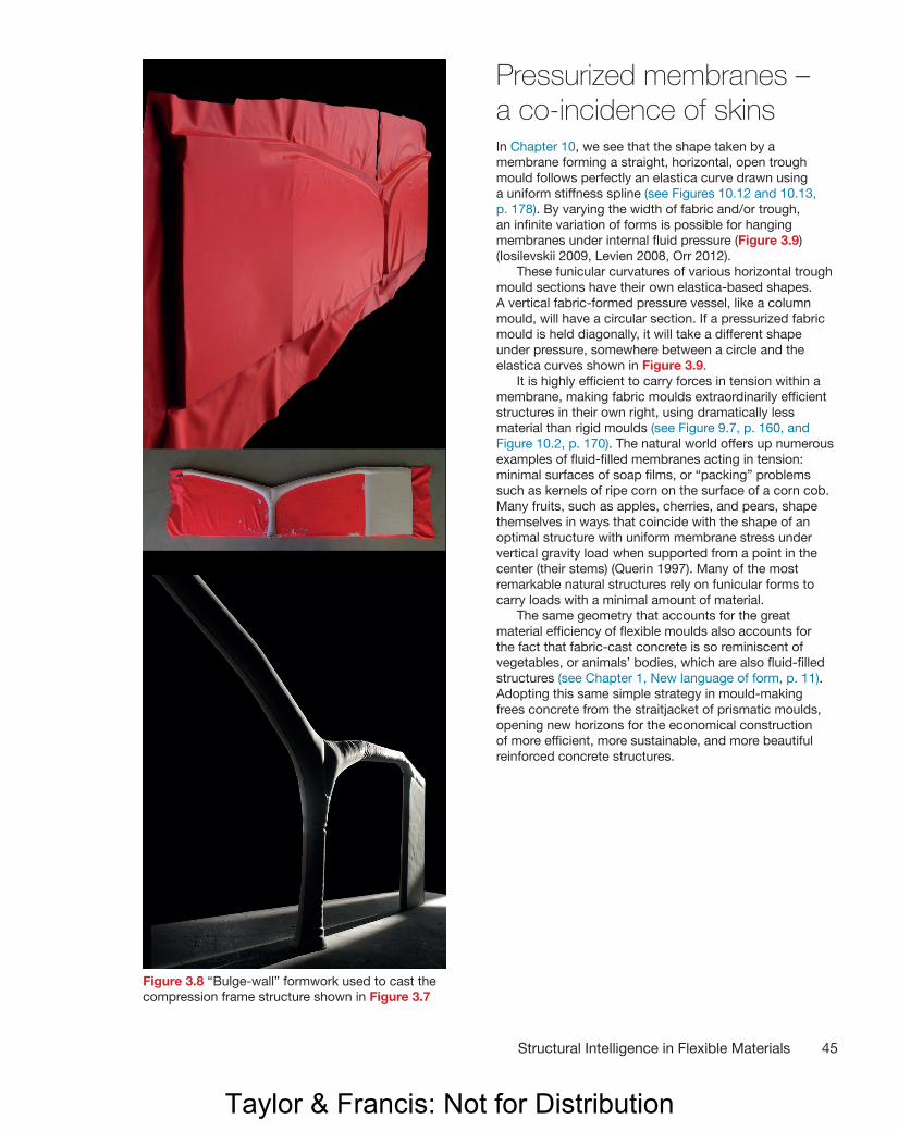
Following curved force flows in fabric-formed structuresThese descriptions demonstrate how the flow of forces through structural material nearly always describes three-dimensional curvatures. As mentioned at the start of this chapter, natural structures that grow material in response to stress concentrations reflect these curvatures in their shapes. It is difficult to build curved structures that follow efficient structural shapes, using conventional, rigid, prismatic building materials. But flexible moulds allow us to construct curved shapes that can more closely follow the theoretical force flow though a structure as a means of reducing the volume of materials consumed in our constructions. Engineering research into more efficiently shaped fabric-formed reinforced concrete beams has begun to explore the full complexity of this strategy (Lee (2010), Orr et al. (2011), Orr et al. (2012), Orr (2012). (See also Figures 10.4, 10.5, and 10.20–32, pp. 172 and 184–91.) Flexible self-forming funicular moulds can even “self-construct” optimized structural shapes automatically (see Chapter 11 generally, and in particular Figures 11.61–81, pp. 236–48). The great structural designer Pier Luigi Nervi (1891–1979), who is most famous for his elegant and efficient structures based on the curvature of force flows, wrote about the prospects for more beautiful (and rational) concrete structures: “One must not forget that all these promising developments are made possible by the progressive liberation of reinforced concrete from the fetters of wooden forms. Until these bonds are totally removed, the architecture of concrete structures is bound to be … an architecture of wooden planks” (Nervi 1956). Flexible moulds present a profoundly different regime from that of conventional, rigid mould construction. Figures 3.7 and 3.8 illustrate one example of a simple strategy for casting a structure that follows force flows in pure compression. By shaping concrete to be placed exclusively in compression, the need for reinforcing steel may be reduced to a minimum. Here a “bulge-wall” technique (see Chapter 8, p. 145 and Figures 12.3–11, pp. 252–7) is used to form what might be called a “compression frame” structure. The hanging chain model (inverted) in Figure 3.7 shows a schematic design for a series of funicular thin-shell vaults (the white strings) (see Chapter 11: Hanging sheet moulds, pp. 220–7 for construction of funicular vaults). These are supported by shallow compression arches that branch into, and guide, the flow of compression force into integrally cast supporting columns (sketched in yellow chalk). The “bulge-wall” formwork for a plaster model of the supporting compression frame structure is shown in Figure 3.8. Note that the thrust of the end-bay arches is received by an integrally cast shear wall.
Figure 3.7 A hanging chain model (top) “draws” the shape of a funicular compression frame structure when inverted (middle). The plaster model (bottom, and Figure 3.8) illustrates the structure cast to this structurally efficient shape
WEST (Fabric Formwork Book) PRINT.indd 64 06/09/2016 15:41
Taylor & Francis: Not for Distribution
45Structural Intelligence in Flexible Materials
Pressurized membranes – a co-incidence of skinsIn Chapter 10, we see that the shape taken by a membrane forming a straight, horizontal, open trough mould follows perfectly an elastica curve drawn using a uniform stiffness spline (see Figures 10.12 and 10.13, p. 178). By varying the width of fabric and/or trough, an infinite variation of forms is possible for hanging membranes under internal fluid pressure (Figure 3.9) (Iosilevskii 2009, Levien 2008, Orr 2012). These funicular curvatures of various horizontal trough mould sections have their own elastica-based shapes. A vertical fabric-formed pressure vessel, like a column mould, will have a circular section. If a pressurized fabric mould is held diagonally, it will take a different shape under pressure, somewhere between a circle and the elastica curves shown in Figure 3.9. It is highly efficient to carry forces in tension within a membrane, making fabric moulds extraordinarily efficient structures in their own right, using dramatically less material than rigid moulds (see Figure 9.7, p. 160, and Figure 10.2, p. 170). The natural world offers up numerous examples of fluid-filled membranes acting in tension: minimal surfaces of soap films, or “packing” problems such as kernels of ripe corn on the surface of a corn cob. Many fruits, such as apples, cherries, and pears, shape themselves in ways that coincide with the shape of an optimal structure with uniform membrane stress under vertical gravity load when supported from a point in the center (their stems) (Querin 1997). Many of the most remarkable natural structures rely on funicular forms to carry loads with a minimal amount of material. The same geometry that accounts for the great material efficiency of flexible moulds also accounts for the fact that fabric-cast concrete is so reminiscent of vegetables, or animals’ bodies, which are also fluid-filled structures (see Chapter 1, New language of form, p. 11). Adopting this same simple strategy in mould-making frees concrete from the straitjacket of prismatic moulds, opening new horizons for the economical construction of more efficient, more sustainable, and more beautiful reinforced concrete structures.
Figure 3.8 “Bulge-wall” formwork used to cast the compression frame structure shown in Figure 3.7
WEST (Fabric Formwork Book) PRINT.indd 65 06/09/2016 15:41
Taylor & Francis: Not for Distribution

46 Fabric Formwork
Figure 3.9 Elastica curves, from uniform stiffness splines, describing cross-sections of a variety of horizontal open trough vessels (Orr 2012, after Josilevskii 2009)
Materials Savings in Flexible Fabric Moulds The remarkable reduction in the amount of material needed to construct a fabric mould, when compared with conventional, rigid, panelized moulds, is explained by two fundamental factors:
1. A flexible fabric, or membrane, resists imposed forces in pure tension, which is the single most efficient way to resist a force. Rigid moulds resist force through bending – a far less efficient mode of structural resistance.
2. A flat, rigid mould is a zero-deflection structure, which means it must work very hard to keep everything as flat as possible. This requires a high degree of stiffness, which inevitably leads to formwork structures of much greater depth, and hence greater material volume and weight. A flat, rigid mould fights against the forces imposed by the wet concrete, but a flexible mould actually uses those forces to produce the most efficient mould shape possible. We can say that flat formwork panels dream of having the curves of a pressurized fabric mould-wall.
These two factors make curved, tension membrane formworks extraordinarily efficient in terms of material use: hundreds of times less material (measured either in terms of weight or volume) is required to construct a robust fabric mould compared to conventional panelized moulds. (Other efficiencies are discussed in Chapter 10.) This stunning efficiency leads to some dramatically different logistical possibilities. For example, the column formworks for the Casa Dent columns (shown in Figures 8.29, 8.30, and 8.38d, pp. 150–1 and 155) were flown from Winnipeg, Canada, to the Island of Culebra, Puerto Rico, as checked luggage. These three duffel bags contained the fabric moulds for 13 individually sculptured columns, plus several spares. After casting, the moulds were flown back, again as checked luggage, for use in future projects.
WEST (Fabric Formwork Book) PRINT.indd 66 06/09/2016 15:41
Taylor & Francis: Not for Distribution
ReferencesChilton, J. 2000. The Engineer’s Contribution to ContemporaryArchitecture: Heinz Isler. London: Thomas Telford Publishing.
Heyman, J. 1997. The Stone Skeleton: Structural Engineering of Masonry Architecture. Cambridge: Cambridge University Press, p. 172.
Heyman, J. 1998. “Hooke’s Cubico-parabolical Conoid.” Notes and Records of the Royal Society of London, 52: 39–50.
Iosilevskii, G. 2009. “Shape of a Soft Container Under Hydrostatic Load.” Journal of Applied Mechanics, 77 (1).
Lee, D. 2010. “Study of Construction Methodology and Structural Behaviour of Fabric-formed Form-efficient Reinforced Concrete Beam.” PhD diss., University of Edinburgh.
Levien, R. 2008. “The Elastica: A Mathematical History.” Electrical Engineering and Computer Sciences University of California at Berkeley, Technical Report No. UCB/EECS-2008-103. 23 August. Last accessed on November 12, 2015 at http://www.eecs.berkeley.edu/Pubs/TechRpts/2008/EECS-2008-103.html.
Nervi, P.L. 1956. Structures. New York: F.W. Dodge, p. 101.
Orr, J. 2012. “Flexible Formwork for Concrete Structures.” PhD diss., Department of Civil Engineering and Architecture, University of Bath.
Orr, J.J., Darby, A.P., Ibell, T.J., Evernden, M.C., and Otlet, M. 2011. “Concrete Structures Using Fabric Formwork.” Structural Engineer, 89: 20–26.
Orr, J.J., Evernden, M., Darby, A.P., and Ibell, T.J. 2012. Proceedings of the Second International Conference on Flexible Formwork, 27–29 June 2012, University of Bath.
Otto, F. and Rasch, B. 1996. Finding Form: Towards an Architecture of the Minimal. Stuttgart: Edition Axel Menges.
Poleni, G. 1748. Memorie istoriche della Gran Cupola del Tempio Vaticano. Padua.
Querin, O. 1997. “Evolutionary Structural Optimisation: Stress Based Formulation and Implementation.” PhD diss.,University of Sydney.
Schlaich, J., Schäfer, K., and Jennewein, M. 1987. “Toward a Consistent Design of Structural Concrete.” PCI Journal, Special Report, 32 (3).
Thompson, D. 1917. On Growth and Form. Cambridge: Cambridge University Press.
Further readingAdriaenssens, S., Block, P., Veenendaal, D., and Williams, C. (eds). 2014. Shell Structures for Architecture: Form Finding and Optimization. London and New York: Routledge.
Allen, E. and Zalewski, W. 2009. Form and Forces: Designing Efficient, Expressive Structures. Hoboken, NJ: John Wiley and Sons.
Engel, H. 2007. Structural Systems. Stuttgart: Hatje Cantz.
47Structural Intelligence in Flexible Materials
WEST (Fabric Formwork Book) PRINT.indd 67 06/09/2016 15:41
Taylor & Francis: Not for Distribution