study of the influence of variation in distances between ... · aprograma de pós-graduação em...
TRANSCRIPT
DOI: http://dx.doi.org/10.1590/1980-5373-MR-2015-0205Materials Research. 2016; 19(1): 202-206 © 2016
* e-mail: [email protected]
1. INTRODUCTIONResearch in the field of low pressure plasma has gained
emphasis, mainly due to to its versatility and the various results obtained in the modification of material physical‑chemical properties 1. However, large scale use is limited mainly because of the high cost of vacuum installations, and its restricted use on high vapor pressure materials such as living tissues 2, 3. As a result, several alternative atmospheric or subatmospheric pressure plasma techniques, such as corona plasma, microwave, microhollow cathode discharge (MHCD), plasma torch and dielectric barrier discharge (DBD) 4.
The DBD technique consists of applying voltage pulses in the range of 5 to 40 kV and at 0,05 to 80 kHz frequencies 4, 5 between two electrodes, at least one of which being coated with dielectric material. At the moment that rupture tension is reached, several micro-discharges spread onto the dielectric surface, yielding filamentary regime DBD plasma. When these micro‑discharges are more numerous, homogeneous and distributed, diffuse regime DBD plasma is achieved 6.
The aim of this paper was to produce a detailed study of DBD plasma behavior when altering the distance between the electrodes in the DBD equipment, as well as of the resulting plasma species. Plasma species is one of the key parameters,
because it influences the amount of species obtained as well as the energy consumed during the treatment of materials, such as film deposition 7, 8, surface sterilization 9, polymers surface treatment 9, dental and skin treatments 10. This knowledge is of utmost importance not only to obtain better results in respective treatments, but also to offer minimal risk to the operator and user when used in biomedical applications.
2. MATERIALS AND METHODS2.1 Experimental Device and Operations
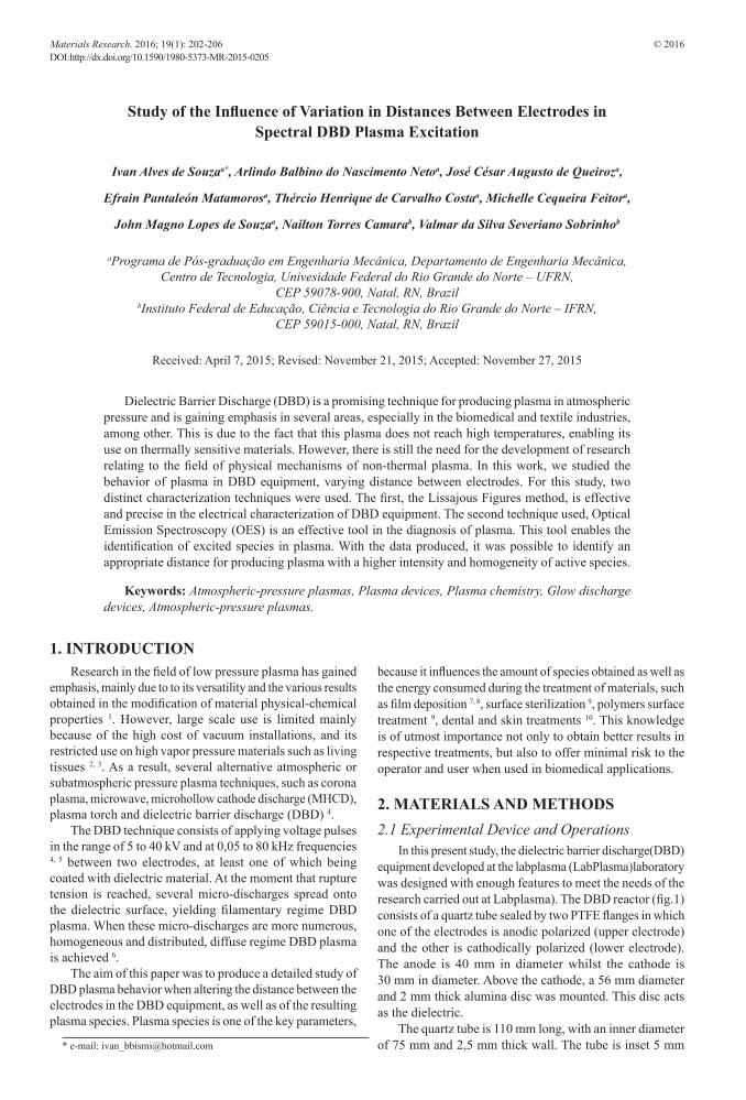
In this present study, the dielectric barrier discharge(DBD) equipment developed at the labplasma (LabPlasma)laboratory was designed with enough features to meet the needs of the research carried out at Labplasma). The DBD reactor (fig.1) consists of a quartz tube sealed by two PTFE flanges in which one of the electrodes is anodic polarized (upper electrode) and the other is cathodically polarized (lower electrode). The anode is 40 mm in diameter whilst the cathode is 30 mm in diameter. Above the cathode, a 56 mm diameter and 2 mm thick alumina disc was mounted. This disc acts as the dielectric.
The quartz tube is 110 mm long, with an inner diameter of 75 mm and 2,5 mm thick wall. The tube is inset 5 mm
Study of the Influence of Variation in Distances Between Electrodes in Spectral DBD Plasma Excitation
Ivan Alves de Souzaa*, Arlindo Balbino do Nascimento Netoa, José César Augusto de Queiroza,
Efrain Pantaleón Matamorosa, Thércio Henrique de Carvalho Costaa, Michelle Cequeira Feitora,
John Magno Lopes de Souzaa, Nailton Torres Camarab, Valmar da Silva Severiano Sobrinhob
aPrograma de Pós-graduação em Engenharia Mecânica, Departamento de Engenharia Mecânica, Centro de Tecnologia, Univesidade Federal do Rio Grande do Norte – UFRN,
CEP 59078-900, Natal, RN, BrazilbInstituto Federal de Educação, Ciência e Tecnologia do Rio Grande do Norte – IFRN,
CEP 59015-000, Natal, RN, Brazil
Received: April 7, 2015; Revised: November 21, 2015; Accepted: November 27, 2015
Dielectric Barrier Discharge (DBD) is a promising technique for producing plasma in atmospheric pressure and is gaining emphasis in several areas, especially in the biomedical and textile industries, among other. This is due to the fact that this plasma does not reach high temperatures, enabling its use on thermally sensitive materials. However, there is still the need for the development of research relating to the field of physical mechanisms of non‑thermal plasma. In this work, we studied the behavior of plasma in DBD equipment, varying distance between electrodes. For this study, two distinct characterization techniques were used. The first, the Lissajous Figures method, is effective and precise in the electrical characterization of DBD equipment. The second technique used, Optical Emission Spectroscopy (OES) is an effective tool in the diagnosis of plasma. This tool enables the identification of excited species in plasma. With the data produced, it was possible to identify an appropriate distance for producing plasma with a higher intensity and homogeneity of active species.
Keywords: Atmospheric-pressure plasmas, Plasma devices, Plasma chemistry, Glow discharge devices, Atmospheric-pressure plasmas.
Study of the Influence of Variation in Distances Between Electrodes in Spectral DBD Plasma Excitation.2016; 19(1) 203
deep in the teflon pieces. To ensure movement of the anode, a 0,1 mm precision ratchet was constructed. This piece allows a variance of distance between the electrodes of up to 100 mm, including during operation, without any risk of electrical accidents to the operator. In this configuration, the electric field generated by the difference in potential applied between the electrodes is homogenous, which guarantees that the generated plasma occupies all the volume delimited by the area immediately below the anode up to the dielectric surface that coats the lower electrode (cathode). In other words, the electrons that are accelerated by a uniform field acquire great energy and collide with gas molecules that occupy that region, promoting collisions that provoke excitation and/or ionization featuring a volume discharge (VD).
The plasma was generated using a high voltage pulsed DC source, with a 200 µs pulse width, obtaining better efficiency in plasma production in comparison to AC sources 11. The source used permits the variation of applied voltage from 0 to 20 kV, and 200 Hz to 1,0 kHz frequency. To generate plasma inside the reactor it is necessary to identify the better distance and voltage between the electrodes, as well as the frequency. The parameters used in this study are shown in Table 1. In each stage, two parameters was fixed whilst a third was variable. As a result, electrical responses, discharge configuration and plasma species generated were analyzed. The total energy consumed and potency of the system were determined from Lissajous Figures built with the assistance of an oscilloscope. The plasma configuration was recorded by photos taken during each discharge application, and the
plasma species were identified with the aid of an Optical Emission Spectrometer.
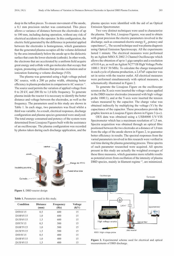
Two very distinct techniques were used to characterize the plasma. The first, Lissajous Figures, was used to obtain with great precision the electric parameters involved in the discharge, such as consumed electric energy Eel, potency and capacitance CT. The second technique used was plasma diagnosis using Optical Emission Spectroscopy. All the experiments lasted 1 minute. The electrical measures were performed by an Agilent MSO‑X 2002 2 Channel Oscilloscope which allows the obtention of up to 1 giga samples and a resolution of 0.014 µs, as well an Agilent N2771B High Voltage Probe 1000:1 30 kV 50 MHz. To calculate the charge transported in each cycle of plasma production, a 2,47nF capacitor was set in series with the reactor outlet. All electrical measures were performed simultaneously with optical measures, as schematically illustrated in Figure 2.
To generate the Lissajous Figure on the oscilloscope screen at the X‑axis were inserted the voltage values applied in the DBD reactor electrodes (measured with high voltage probe 1000:1), and at the Y‑axis were inserted the tension values measured by the capacitor. The charge value was obtained indirectly by multiplying the voltage (V) by the capacitance of the capacitor. These procedures provide the graphic known as Lissajous Figure shown in Figure 3 (a‑c).
OES data was obtained using a USB4000 UV‑VIS Spectrometer which has a maximum resolution of 1,5 nm. Spectra acquisition was obtained through an optical fibre positioned between the two electrodes at a distance of 1,0 mm from the edge of the anode shown in Figure 2, to guarantee better efficiency in results. The spectral responses from the varied parameters involved in this research were verified in real time during the plasma generating process. Three spectra of each parameter researched were acquired. All spectra present in this study are actually the weighted averages of these three measures, which guarantee more reliable results as potential errors from oscillation of the intensity of plasma DBD species, mainly in filament regime 12, are minimized.
Table 1. Parameters used in this study.
Condition Distance (mm)
Frequency (Hz)
Voltage (KV)
D5F6V15 0,5 600 15D10F6V15 1,0 600 15D15F6V15 1,5 600 15D5F5V15 0,5 500 15D10F5V15 1,0 500 15D15F5V15 1,5 500 15D5F4V15 0,5 400 15D10F4V15 1,0 400 15D15F4V15 1,5 400 15
Figure 1. DBD reactor design
Figure 2. Experimental scheme used for electrical and optical measurements of DBD discharge.

Souza et al.204 Materials Research
3. RESULTS AND DISCUSSION3.1 Analysis
When analyzing the lines obtained from OES, we observed that the most intense were N2 (357 nm) and N2 (337 nm) followed by three peaks all in the UV region. These results are consistent with those obtained in literature 13. When applying a potential difference of 15 kV between electrodes during 200 µs (pulse width) in frequencies of 400, 500 and 600 Hz, spectra for electrical and optical measurements were obtained
as shown in Figures 3 (a‑c) and 3 (d‑e), respectively. Analysis shows that in the shortest distance between the electrodes the highest spectral intensity occurred. However, it was also verified that the energy per cycle Eel in this condition is higher. In other words, a higher density of active species was obtained due to higher energy consumption. If, on the one hand, energy consumption is a negative factor in industrial applications, on the other the spectra intensity reflects the density of active species which is important for surface modifications.
Figure 3. (a ‑ c) Lissajous Figures (loading curves) varying distances between electrodes at 400,500 and 600Hz frequencies, (d ‑ e) spectra intensities obtained in experiments.
Study of the Influence of Variation in Distances Between Electrodes in Spectral DBD Plasma Excitation.2016; 19(1) 205
Therefore, a parameter that provides an indication of active species density per energy consumed can be very important in evaluating the performance efficiency of a DBD device. Since the major species for air atmospheric discharge are in the range of 300 nm to 420 nm, corresponding to N2 spectra lines (C3Πu-B
3Πg) 14, the integral spectra intensity can
be provided by the value in equation 1 15, 16, obtained from the area under the curve shown in Figure 3 (d‑e). As such, the Is/Eel ratio provides the DBD reactor efficiency in active plasma species production. Table 2 demonstrates the Eel, Is and Is/Eel values for all three distances and frequencies studied. Observations show that in the case of the shortest distance between electrodes the device was at its highest efficiency (Is/Eel)
17, the only exception being when a 500 Hz frequency
was used. In this case, the highest efficiency occurred at a distance of 1,0 mm.
( )420
s300
I I dλ λ= ∫ (1)
4. DISCUSSIONRegarding reactor capacitance in relation to distance,
variations in capacitance are expected whenever there are changes in distances between electrodes. In fact this event is observed when we verify the dQ/dV inclination for total capacitance. These calculations were made for the three distances studied in 400, 500 and 600 Hz frequencies. These values are shown in Table 3. These results are in full accordance with equation 2 18. As the dielectric thickness is constant, the increase in distance between electrodes causes the decrease in the total capacitance of the reactor.
dQdV
=TC (2)
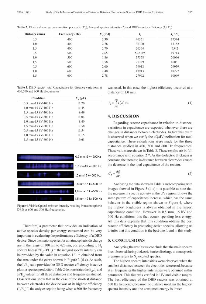
Analyzing the data shown in Table 3 and comparing with images showed in Figure 3 (d‑e) it is possible to note that the increase in spectra activity in the UV region follows the same pattern of capacitance increase, which has the same behavior in the visible region shown in Figure 4, where the highest brightness is always obtained in the largest capacitance condition. However in 0,5 mm, 15 kV and 600 Hz conditions this fact occurs spending less energy. All this data explains that this condition obtains the best reactor efficiency in producing active species, allowing us to infer that this condition is the best one found in this study.
5. CONCLUSIONSAnalyzing the results we conclude that the main spectra
lines observed during dielectric barrier discharge at atmospheric pressure refers to N2 excited spectra.
The highest spectra intensities were observed when the smallest distances between the electrodes were used, because at all frequencies the highest intensities were obtained in this parameter. This fact was verified in UV and visible ranges. The best efficiency of the DBD reactor was obtained at 600 Hz frequency, because the distance used has the highest spectra intensity and the consumed energy is lower.
Table 2. Electrical energy consumption per cycle (Eel), Integral spectra intensity (Is) and DBD reactor efficiency (Is / Eel)
Distance (mm) Frequency (Hz) Eel (mJ) Is Is / Eel
0,5 400 2,30 40351 175441,0 400 2,76 36300 131521,5 400 2,70 20364 75420,5 500 2,65 522389 197131,0 500 1,86 37378 200961,5 500 1,58 25329 160310,5 600 2,00 59918 299591,0 600 2,40 43913 182971,5 600 2,78 27992 10069
Table 3. DBD reactor total Capacitance for distance variations at 400,500 and 600 Hz frequencies
Condition CT (pF)0,5 mm‑15 kV‑400 Hz 11,701,0 mm‑15 kV‑400 Hz 11,451,5 mm‑15 kV‑400 Hz 9,490,5 mm‑15 kV‑500 Hz 11,041,0 mm‑15 kV‑500 Hz 8,401,5 mm‑15 kV‑500 Hz 7,580,5 mm‑15 kV‑600 Hz 11,541,0 mm‑15 kV‑600 Hz 11,151,5 mm‑15 kV‑600 Hz 9,61
Figure 4. Visible Optical emission intensity resulting from atmospheric DBD at 600 and 500 Hz frequencies.
Souza et al.206 Materials Research
6. REFERENCES1. Alves C Jr, Guerra CL No, Morais GH, Silva CF and Hajek
V. Nitriding of titanium disks and industrial dental implants using hollow cathode discharge. Surface and Coatings Technology. 2005; 194(2):196‑202. http://dx.doi.org/10.1016/j.surfcoat.2004.10.009.
2. Kanazawa S, Kogoma M, Okazaki S and Moriwaki T. Glow plasma treatment at atmospheric pressure for surface modification and film deposition. Nuclear Instruments & Methods in Physics Research. Section B, Beam Interactions with Materials and Atoms. 1989; 37–38:842-845.
3. Yokoyama T, Kogoma M, Moriwaki T and Okazaki S. The mechanism of the stabilisation of glow plasma at atmospheric pressure. Journal of Physics. D, Applied Physics. 1990; 23(8):1125-1128.
4. Napartovich AP. Overview of atmospheric pressure discharges producing nonthermal plasma. Plasmas and Polymers. 2001; 6(1):1-14.
5. Eliasson B and Kogelschatz U. Nonequilibrium volume plasma chemical processing. IEEE Transactions on Plasma Science. 1991; 19(6):1063-1077. http://dx.doi.org/10.1109/27.125031.
6. Pietsch GJ. Peculiarities of Dielectric Barrier Discharges. Contributions to Plasma Physics. 2001; 41(6):620-628.
7. Haiyan H, Qian G, Xiwen Z and Gaorong H. Cold deposition of large‑area amorphous hydrogenated silicon films by dielectric barrier discharge chemical vapor deposition. Thin Solid Films. 2011; 519(15):5038-5042.
8. Da Ponte G, Sardella E, Fanelli F, Van Hoeck A, d’Agostino R, Paulussen S, et al. Atmospheric pressure plasma deposition of organic films of biomedical interest. Surface and Coatings Technology. 2011; 205(Suppl 2):S525‑S528. http://dx.doi.org/10.1016/j.surfcoat.2011.03.112.
9. Kostov KG, Rocha V, Koga‑Ito CY, Matos BM, Algatti MA, Honda RY, et al. Bacterial sterilization by a dielectric barrier discharge (DBD) in air. Surface and Coatings Technology. 2010; 204(18):2954‑2959. http://dx.doi.org/10.1016/j.surfcoat.2010.01.052.
10. Daeschlein G, Scholz S, Ahmed R, Majumdar A, Von Woedtke T, Haase H, et al. Cold plasma is well‑tolerated and does not disturb skin barrier or reduce skin moisture. JDDG: Journal der Deutschen Dermatologischen Gesellschaft. 2012; 10(7):509-515. http://dx.doi.org/10.1111/j.1610‑0387.2012.07857.x.
11. Shuhai L and Neiger M. Excitation of dielectric barrier discharges by unipolar submicrosecond square pulses. Journal of Physics. D, Applied Physics. 2001; 34(11):1632-1638.
12. Souza IA. Descarga em barreira dielétrica: construção de um reator DBD e caracterização mediante análises ópticas e elétricas do plasma produzido. [Dissertation]. Natal: Universidade Federal do Rio Grande do Norte; 2013.
13. Qiu X, Mellinger A, Wirges W and Gerhard R. Spectroscopic study of dielectric barrier discharges in cellular polypropylene ferroelectrets. Applied Physics Letters. 2007; 91:132905.
14. Staack D, Farouk B, Gutsol A and Fridman A. DC normal glow discharges in atmospheric pressure atomic and molecular gases. Plasma Sources Science & Technology. 2008; 17(2):025013.
15. Rajasekaran P, Mertmann P, Bibinov N, Wandke D, Viöl W and Awakowicz P. Filamentary and homogeneous modes of Dielectric Barrier Discharge (DBD) in air: investigation through plasma characterization and simulation of surface irradiation. Plasma Processes and Polymers. 2010; 7(8):665-675. http://dx.doi.org/10.1002/ppap.200900175.
16. Kuchenbecker M, Bibinov N, Kaemlimg N, Wandke D, Awakowicz P and Viöl W. Characterization of DBD plasma source for biomedical applications. Journal of Physics. D, Applied Physics. 2009; 42(4):045212.
17. Souza IA, Nascimento IO, Nascimento Neto AB, Nascimento LA, Souza JM, Costa TH, et al. Estudo da eficiência de um reator de descarga por barreira dielétrica (DBD), na produção das espécies ativas do segundo sistema positivo do N2. HOLOS. 2015; 3:44-53.
18. Mahoney J, Zhu W, Johnson VS, Becker KH and Lopez JL. Electrical and optical emission measurements of a capillary dielectric barrier discharge. The European Physical Journal. 2010; 60(3):441-447.