mestrado integrado em engenharia mecânica aerodynamics · mestrado integrado em engenharia...
TRANSCRIPT
Mestrado Integrado em Engenharia Mecânica Aerodynamics
1st Semester 2012/13
Exam “1ª época”, 18 January 2013 Name : Time : 8:00 Number: Duration : 3 hours 1st
Part : No textbooks/notes allowed 2nd
Part : Textbooks allowed
1st Part
Indicate if the sentences are true (T) or false (F) in the empty squares. For each theme, any
combination of true and false is possible. The classification of each answer is the following:
Correct answer 0.25 marks.
Empty square 0 marks.
Incorrect answer -0.15 marks
1. The Reynolds-Averaged Navier-Stokes equations
require a turbulence model to match the number of unknowns with the number of
equations.
allow the determination of instantaneous velocity components.
cannot be applied to flows including separation.
are appropriate for the calculation of flows at low Reynolds numbers.
2. The aerodynamic centre of a lifting foil
is the location around which the pitching moment is maximum.
can only be determined for an ideal fluid.
requires a linear variation of the lift coefficient with the angle of attack to exist.
can never coincide with the pressure centre.
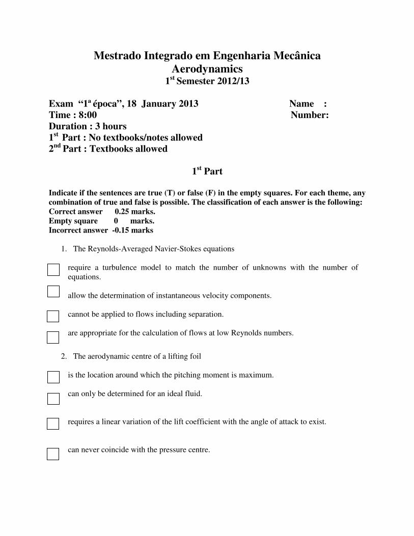
3. The figure below presents the neutral stability curves of laminar boundary
profiles.
Ri corresponds to the transition
Region D corresponds to the unstable region of velocity profile
Region C is typical of adverse pressure gradient flows
The variable plotted in the vertical axe
applied to the velocity profile
4. The figure below illustrates the lift and drag coefficients of an airfoil whitout high
devices and with four different flaps (plain
angle of attack α.
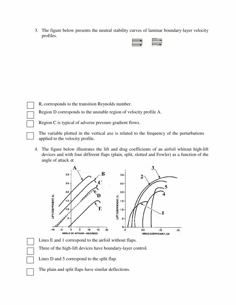
Lines E and 1 correspond to the airfoil without flaps.
Three of the high-lift devices have boundary
Lines D and 5 correspond to the split
The plain and split flaps have similar deflections
The figure below presents the neutral stability curves of laminar boundary
corresponds to the transition Reynolds number.
Region D corresponds to the unstable region of velocity profile A.
Region C is typical of adverse pressure gradient flows.
ble plotted in the vertical axe is related to the frequency of the perturbations
applied to the velocity profile.
The figure below illustrates the lift and drag coefficients of an airfoil whitout high
devices and with four different flaps (plain, split, slotted and Fowler) as a function of the
correspond to the airfoil without flaps.
lift devices have boundary-layer control.
to the split flap.
have similar deflections.
The figure below presents the neutral stability curves of laminar boundary-layer velocity
is related to the frequency of the perturbations
The figure below illustrates the lift and drag coefficients of an airfoil whitout high-lift
as a function of the
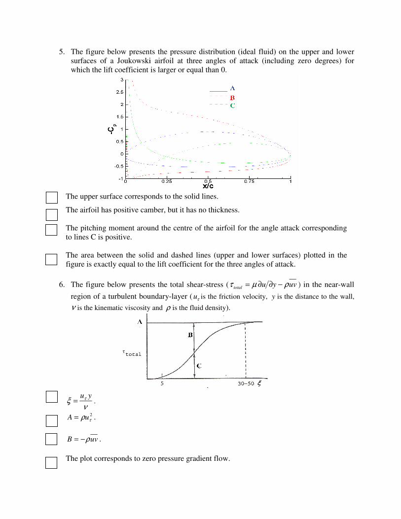
5. The figure below presents the pressure distribution (ideal fluid) on the upper and lower
surfaces of a Joukowski a
which the lift coefficient is larger or equal
The upper surface corresponds to the solid lines
The airfoil has positive camber, but it has no t
The pitching moment around the centre of the airfoil for the angle attack corresponding
to lines C is positive.
The area between the solid and dashed lines (upper and lower surfaces) plotted in the
figure is exactly equal to the lift coefficient for the three angles of attack.
6. The figure below presents the total shear
region of a turbulent boundary
ν is the kinematic viscosity
ν
ξ τ yu= .
2
τρuA = .
uvB ρ−= .
The plot corresponds to zero pressure gradient
The figure below presents the pressure distribution (ideal fluid) on the upper and lower
Joukowski airfoil at three angles of attack (including zero degrees)
which the lift coefficient is larger or equal than 0.
The upper surface corresponds to the solid lines.
The airfoil has positive camber, but it has no thickness.
The pitching moment around the centre of the airfoil for the angle attack corresponding
The area between the solid and dashed lines (upper and lower surfaces) plotted in the
equal to the lift coefficient for the three angles of attack.
The figure below presents the total shear-stress ( uvyutotal ρµτ −∂∂= )
region of a turbulent boundary-layer ( τu is the friction velocity, y is the distance to the wall
is the kinematic viscosity and ρ is the fluid density).
The plot corresponds to zero pressure gradient flow.
The figure below presents the pressure distribution (ideal fluid) on the upper and lower
irfoil at three angles of attack (including zero degrees) for
The pitching moment around the centre of the airfoil for the angle attack corresponding
The area between the solid and dashed lines (upper and lower surfaces) plotted in the
) in the near-wall
is the distance to the wall,
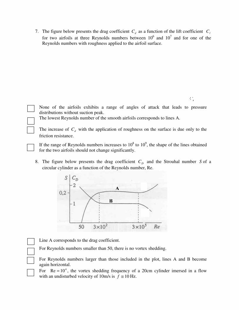
7. The figure below presents the drag coefficient
for two airfoils at three Reynolds number
Reynolds numbers with roughness applied to the airfoil surface
None of the airfoils exhibits a range of angles of attack that leads to pressure
distributions without suction peak.
The lowest Reynolds number of the smooth airfoils corresponds to lines
The increase of dC with the application of roughness on the surface is due only to the
friction resistance.
If the range of Reynolds numbers
for the two airfoils should not change significantly
8. The figure below presents the drag coefficient
circular cylinder as a function of the
Line A corresponds to the drag coefficient
For Reynolds numbers smaller than
For Reynolds numbers larger than those included in the plot,
again horizontal.
For 410Re = , the vortex shedding frequency of a 20cm cylinder imersed in a flow
with an undisturbed velocity of 10m/s is
The figure below presents the drag coefficient dC as a function of the lift coefficient
for two airfoils at three Reynolds numbers between 106 and 10
7 and for one of the
Reynolds numbers with roughness applied to the airfoil surface.
one of the airfoils exhibits a range of angles of attack that leads to pressure
ibutions without suction peak.
number of the smooth airfoils corresponds to lines A
with the application of roughness on the surface is due only to the
numbers increases to 108 to 10
9, the shape of the lines
for the two airfoils should not change significantly.
The figure below presents the drag coefficient DC and the Strouhal
circular cylinder as a function of the Reynolds number, Re.
s to the drag coefficient.
numbers smaller than 50, there is no vortex shedding.
numbers larger than those included in the plot, lines A and
, the vortex shedding frequency of a 20cm cylinder imersed in a flow
with an undisturbed velocity of 10m/s is 10≅f Hz.
as a function of the lift coefficient lC
and for one of the
one of the airfoils exhibits a range of angles of attack that leads to pressure
A.
with the application of roughness on the surface is due only to the
the shape of the lines obtained
Strouhal number S of a
and B become
, the vortex shedding frequency of a 20cm cylinder imersed in a flow
Mestrado Inte
Exam “1ª época”, 18 January 2013 Name :Time : 8:00 Number:
Duration : 3 hours 1st
Part : No textbooks/notes allowed2nd
Part : Textbooks allowed
1. The figure above presents the aerodynamic
zero angle of attack, assume that the friction resistance coefficient of the airfoil may be
estimated from a zero pressure gradient flat plate boundary
number (with identical boundary
transition from laminar to turbulent flow is instantaneous, i.e. critical
equal to transition Reynolds number
×= − /s,m1051.1 25
arν
Mestrado Integrado em Engenharia MecânicaAerodynamics
1st Semester 2012/13
época”, 18 January 2013 Name :8:00 Number:
o textbooks/notes allowed extbooks allowed
2nd Part
The figure above presents the aerodynamic coefficients of a NACA 63009
zero angle of attack, assume that the friction resistance coefficient of the airfoil may be
estimated from a zero pressure gradient flat plate boundary-layer at the same Reynolds
number (with identical boundary-layers on the two sides of the airfoil).
transition from laminar to turbulent flow is instantaneous, i.e. critical Reynolds
Reynolds number.
transitioncritical ReRe == ,kg/m2.1 3
arρ
grado em Engenharia Mecânica
época”, 18 January 2013 Name : 8:00 Number:
NACA 63009 airfoil. For
zero angle of attack, assume that the friction resistance coefficient of the airfoil may be
layer at the same Reynolds
ers on the two sides of the airfoil). Assume that
Reynolds number
For angle of attack equal to zero
a) In conditions of natural transition
boundary-layer.
b) Is it possible to estimate the
forced at the leading edge for both sides of the airfoil
answer.
c) For the flow with natura
supplemented by an eddy
The flow solver available includes the standard
model. Which model is the best choice to perform the calculation?
justification to your answer
d) Estimate the minimum relative roughness
friction drag coefficient
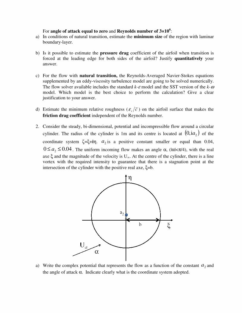
2. Consider the steady, bi-dimensional, potential and incompressible flow
cylinder. The radius of the cylinder is 1m and its centre is located at
coordinate system ζ=ξ+
04.00 2 ≤≤ a . The uniform incoming flow makes an angle
axe ξ and the magnitude of the velocity is
vortex with the required intensity to guarantee that there is a stagnation point at the
intersection of the cylinder with the
a) Write the complex potential that represents the flow as a function of the constant
the angle of attack α. Indicate clearly what is the coordinate system adopted.
angle of attack equal to zero and Reynolds number of 3×10⁶:
In conditions of natural transition, estimate the minimum size of the region with laminar
Is it possible to estimate the pressure drag coefficient of the airfoil when transition is
forced at the leading edge for both sides of the airfoil? Justify quantita
natural transition, the Reynolds-Averaged Navier-
eddy-viscosity turbulence model are going to be solved numerically.
The flow solver available includes the standard k-ε model and the SST version of
model. Which model is the best choice to perform the calculation?
your answer.
Estimate the minimum relative roughness ( crε ) on the airfoil surface that makes the
independent of the Reynolds number.
dimensional, potential and incompressible flow
cylinder. The radius of the cylinder is 1m and its centre is located at
+iη. 2a is a positive constant smaller or equal than 0.
The uniform incoming flow makes an angle α, (|α|<π/4),
and the magnitude of the velocity is U∞. At the centre of the cylinder, there is a line
vortex with the required intensity to guarantee that there is a stagnation point at the
intersection of the cylinder with the positive real axe, ξ=b.
Write the complex potential that represents the flow as a function of the constant
Indicate clearly what is the coordinate system adopted.
region with laminar
coefficient of the airfoil when transition is
quantitatively your
Stokes equations
viscosity turbulence model are going to be solved numerically.
version of the k-ω
model. Which model is the best choice to perform the calculation? Give a clear
) on the airfoil surface that makes the
around a circular
cylinder. The radius of the cylinder is 1m and its centre is located at ( )2i,0 a of the
is a positive constant smaller or equal than 0.04,
/4), with the real
At the centre of the cylinder, there is a line
vortex with the required intensity to guarantee that there is a stagnation point at the
Write the complex potential that represents the flow as a function of the constant 2a and
Indicate clearly what is the coordinate system adopted.
b) Determine the range of angles of attack ( minα and maxα ) that guarantees the existence of a
stagnation point (( ) ( )
11
11,
== pCpCηξ ) with a real coordinate smaller or equal than -0.985 and an
absolute value of the imaginary coordinate of that same point below 0.2 (( )
985.01
1−≤
=pCξ
and ( ) 2.01
1 <=pCη ). Select the value of 2a that leads to the largest value of maxα .
Consider the Karmán-Treftz conformal mapping given by
( ) ( )( ) ( )
96.1andiwith =+=−−+
−++= kyxz
bb
bbkbz
kk
kk
ζζ
ζζ
that transforms the cylinder into an airfoil.
c) Determine the value of 2a that leads to the highest lift coefficient at zero degrees angle of
attack ( )( )0formax
=αlC and determine the equation that relates lC to α for that value
of 2a .
d) For the value of 2a of the previous question and zero lift angle, determine the maximum
and minimum values of the pressure coefficient in the transformed (airfoil) plane and
its location.
3. A finite wing of a glider has an aspect ratio of Λ=14, a mean chord of 1.5m, no twist and
its section is a NACA 63009 airfoil ( lC and dC given in the figure of problem 1). Assume
that the circulation along the span is elliptic and that the drag coefficient of the glider is
equal to the drag coefficient of the wing.
a) For the wing section, determine the pitching moment coefficient around the centre of the
airfoil and the location of the pressure centre.
b) If the glider is flying at constant speed in a region without wind, estimate the minimum
loss of altitude for each km flown.
c) In the conditions of question b), estimate at what angle of attack is the wing operating.
d) In the conditions of question b), determine the relation between the weight and the speed
of the glider.