study of use, durability, and cost of corrugated steel … , \ . l . study of use, durability, and...
TRANSCRIPT

-
,.' REPORT
, \ . l .
STUDY OF USE, DURABILITY, AND CGSr OF CORRUGATED stEEL PIPE ON liHE,
I ,MISSOURI HIGHWAY AND {'RANSPORtA11'ON '. '< DEPARtMENTS HIGHWAY SYSTEM ' .
MI~SOURI STATE LIBRARY .. .
, "J ~
'r::. " FEB '08 2002
~i DOCUMENTS DIVISION 'f, •
This study
Transportation
ABSTRACT
reviewed the Missouri
Department ' s policy of
Highway
culvert
and
type
selection, durability of culvert pipe, and costs of
replacement or rehabilitation of corrugated metal pipe . A
literature search , survey of adjoining States , and results
of Department investigations and field trials are included .
Zinc - coated corrugated steel pipe (CSP) was found to be
much less durable than /reinforced concrete pipe (RCPJ .
Current field reports indicate CSP is being replaced as
early as 20 years of age due to rusting out of the lower
portion of the flowline (invert).
It is recognized that CSP has a lower initial installed
cost than Rep. However , CSP is e x pected to be replaced one
to four times during the anticipated life of an Rep .
At this time, it is concluded that in order for CSP to
be an equal alternate to RCP for culverts under roadways
carrying high volumes of traffic, the pipe should have an
expected life of at least 100 years.
Costs for culvert replacement were found to be
increasing annually and becoming a major item in the
Department ' s budget.
personnel placed 37 , 583
In 1986 , the Department ' s own
linear feet of C$P at a cost of
$968,890 and CSP were replaced or lined by contract on
94 . 653 miles of roadway at a cost of $450,094 .
MISSOURI STATE LlB.RARY
FEB Oe 2002
DOCUMENTS DIViSiON
Various coatings f o r CSP were considered that ext e nd
the service life of esp . However , no coating was found that
extended the life and durability of CSP to the extent
it is comparable to RCP .
that
The Department is reviewing its policy on materials
used for crossroad pipe culverts .
STUDY OF USE, DURABILITY, AND COST
OF CORRUGATED STEEL PIPE ON THE
MISSOURI HIGHWAY AND TRANSPORTATION
DEPARTMENT ' S HIGHWAY SYSTEM
STUDY NUMBER MR 87-1
Prepared By
MISSOURI HIGHWAY AND TRANSPORTATION DEPARTMENT
DIVISION OF MATERIALS AND RESEARCH
MAY 1987
TABLE OF CONTENT S
I n troduction
Conclusions a nd Recommendations ... .• • . .. ••• .• • • ...•..
Scope ........ . . . . . . . .... . . . . .. . . . ..• . . . . •..... .. ..•..
Discussion
Appendices
- iv -
Page
1
3
5
6
38
Table
I.
II.
III.
IV .
V.
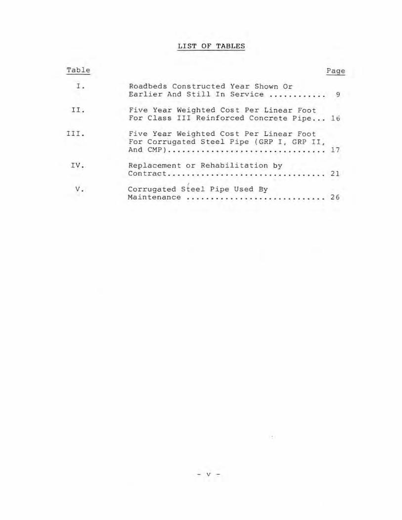
LIST OF TABLES
Roadbeds Constructed Year Shown Or Earlier And Still In Service ... .. . .. .. .. 9
Five Year Weighted Cost Per Linea r Foot For Class III Reinforced Concrete Pipe .. . 16
Five Year Weighted Cost Per Linear Foot For Corrugated Steel Pipe (GRP I, GRP II , And eMP) ....... . . .. ...... ... ............. 17
Replacement or Rehabilitation by Contract ....... . ............... .. . .. . .. .. 21
, Corrugated Steel Pipe Used By Main te nan ce ................... ...• ... ... 26
- v -

Figure
1.
2 .
3 .
LIST OF FI GURES
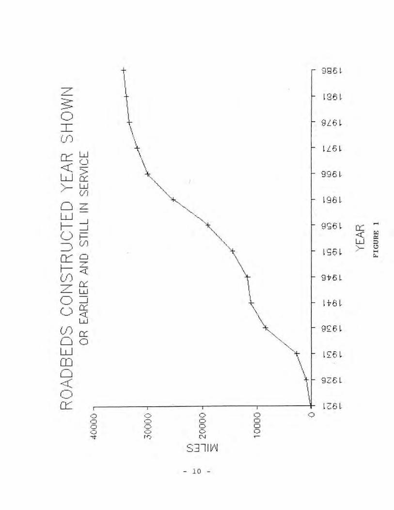
Roadbeds Constructed Year Shown Or Earlier And Still In Service ....... ... . . 10
Roadbeds Constructed Year Shown Or Earlie r And Still In Service By System ......... . .. . .. . .... ...... ..... . .. 11
Culvert Pipe Purchased . .... .•.... ....... 27
- vi -

LIST OF APPENDICES
Appendix
A Design Policy 38
B Roadbed Life ......................... .. . 44
c Pipe Quantities Used By Maintenance 46
D Pipes Replaced Or Rehabilitated By Contract .. . .......... . . ... ... ... . . . .. ... 49
E Culvert Survey Of Crossroad Replacements Or Rehabilitation .... ........... ......... 66
F Culver t Pipe , References ...... ... ...... . .. 78
G Extracts From Selected References ... .... 82
H Survey Of Surrounding States ! Usage Of Corruga ted Metal Pipe ... ..... . .... . . . 102
- vii -

INTRODUCTION
The Department ' s current policy for selection of type
of culvert pipe to be used has been in effect for many years
and is contained in Chapter IX , Section 9-10 of the Surveys
and Plans Design Manual . A copy of that policy is shown in
Appendix A. Briefly , the policy allows corrugated metal
pipe for all entrances but restricts the use of corrugated
metal pipe for crossroad installation to roadways with less
than 400 ADT regardles~ of surface and roadways with more
than 400 ADT that do not have a concrete or asphaltic
concrete surface .
Corrugated metal pipe has only been permitted for
culvert installations in those areas that when the need for
replacement occurs, it is not detrimental to or does not
seriously impede the flow of traffic . Examples are
entrances, approaches and crossroad culverts on those
facilities with lower traffic volumes and which do not have
a high type paveme n t surface . On the remai nder of the
highway system , only those culvert materials which will give
the greatest known life expectancy are permitted . For
culverts and storm water conveyance,
concrete .
that material is
There were several reasons for the development of the
current design policy .
integrity of the facility .
The first being to maintain the
It was thought that if a culvert
pipe had to be replaced under a high traffic volume roadway
- 1 -

there would be an unacceptable disruption of traffic .
Second , in many cases , the initial lanes of construction may
ultimately serve as part of a multi - lane facility and the
culvert pipe needs to have as long a life as possible .
Third , when an existing highway facility is no longer needed
by the Department it is normally relinquished to local
governmental agencies such as counties or cities where it
continues to serve for many years.
Due to the necessi~y for replacement of corrugated
steel pipe by contract and due to the increasing quantity of
corrugated steel pipe being purchased and installed by the
Department ' s own forces this study was initiated to review
the use , durability , a nd cost of zinc-coated corrugated
stee"l pipe .
- 2 -
It is
corrugated
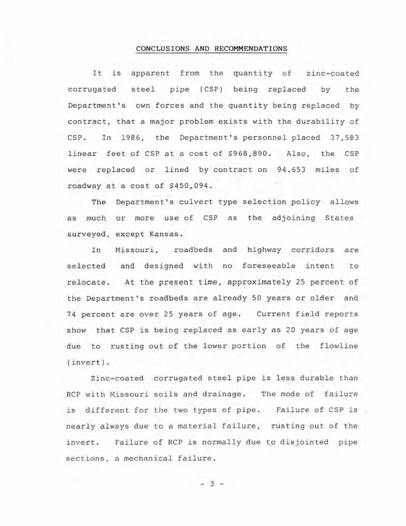
CONCLU S I ONS AND RECOMMENDAT IONS
apparent from
steel pipe
the
(CSP)
quantity of
being replaced
zinc-coated
by the
Department ' s own forces and the quantity being replaced by
contract, that a major problem exists with the durability of
CSP. In 1986 , the Department ' s personnel placed 37 , 583
linear feet of CSP at a cost of $968 , 890. Also, the CSP
were replaced or lined by contract on 94 . 653 miles of
roadway at a cost of S450~094 .
The Department ' s culvert type selection policy allows
as much or more use of CSP as the adjoining States
surveyed, except Kansas .
In
selected
relocate.
Missouri , roadbeds and highway corridors are
and designed with no foreseeable intent to
At the present time, approximately 25 percent of
the Department ' s roadbeds are already 50 years or older and
74 percent are over 25 years of age. Current field reports
show that CSP is being replaced as early as 20 years of age
due to rusting out of the lower portion of the flowline
(invert) .
Zinc - coated corrugated steel pipe is less durable than
RCP with Missouri soils and drainage .
is different for the two types of pipe .
nearly always due to a material failure ,
The mode of failure
Failure of CSP is
rusting out of the
invert . Failure of Rep is normally due to disjointed pipe
sections , a mechanical failure .
- 3 -
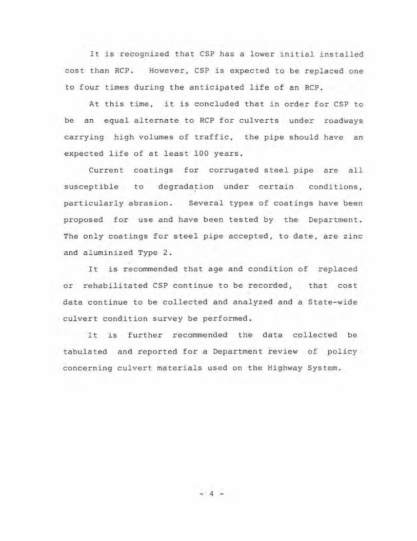
It is recognized that CSP has a lower initial installed
cos t than RCP . However , CSP is expected to be replaced one
to four times during the anticipated life of an RCP .
At this time , it is concluded that in order for CSP to
be an equal alternate to Rep for culverts under roadways
carrying high volumes of traffic , the pipe should have an
expected life of at least 100 years.
Current coatings for corrugated steel pipe are all
susceptible to degradation under certain , conditions,
particularly abrasion . Several types of coatings have been
proposed for use and have been tested by the Department .
The only coatings for steel pipe accepted, to date, are zinc
a nd aluminized Type 2 .
It is recommended that age and condition of replaced
or rehabilitated CSP continue to be recorded , that cost
data continu e to be collec t ed and analyzed and a State-wide
culvert condition survey be performed .
It is further recommended the data collected be
tabulated and reported for a Department review of policy
concerni ng culvert materials used on the Highway System .
- 4 -

SCOPE
The proposed method of study was to review the
Department's current design policy, determine the age of the
roadbed of the Department's existing highway system, review
the economics of concrete and corrugated steel pipe placed
by con trac t • review some recent contracts that required
lining or replacing the corrugated steel pipe , review the
quantity and cost of corrugated steel pipe being purchased
and placed by the Departmen t ' s own forces , conduct a
telephone survey of six adjoining states , and conduct a
literature search of research pertaining to concrete and
corrugated steel pipe .
Field data of corrugated steel pipe was obtained by
District personnel and the Materials and Research Division ' s
Field Office .
Quantities and cost were obtained from various
Divisions within the Department .
- 5 -

DISCU SS I ON
Cur rent Design Polic y - The Department ' s current policy
for selection of type of culvert pipe to be used has been in
effect for many years . The policy allows corrugated metal
pipe (CMP) under a l l entrances , unde r roadways with less
than 400 average daily traffic (ADT) regardless of surface
type , and under roadways with more than 400 ADT that do not
have a portland cement co ncrete or asphaltic concrete
surface. A copy of the Department ' s curren~ design policy
is contained in the Surveys a nd Plans Design Manual , Chapter
IX , Section 9 - 10 and is shown in Appendix A.
The Department ' s design policy also requires that when
Group I or II pipe is specified , the hydraulic design is to
be based on CMP . Due to CMP having a higher roughness
coefficient a nd lower full flow capacity t ha n rei nforced
concrete pipe (Rep). basing the hydraulic design on CMF
results in a larger diameter pipe than if the hydraulic
design were based on RCP . The size , shape , and direction of
corrugations, i.e., annular or helical, will also affect the
coefficient of roughness . Coatings such as bituminous or
polymer materials cannot be used to lower the coefficient of
roughness for CMP because the coating will be lost first
leav ing
CMP .
the hydraulic condition controlled by the uncoated
Corrugated metal pipe in this report means zinc - coated
co rrugated steel pipe (CSP) , aluminized Type 2 - coated
- 6 -

corrugated steel pipe, or corrugated aluminum alloy pipe.
Pipe is specified as Group I when corrugated metallic - coated
steel pipe, RCP, or vitrified clay pipe is allowed. Pipe is
specified as Group II when corrugated metallic-coated steel
pipe, Rep, or aluminum alloy pipe is allowed . Zinc - coated
corrugated steel pipe is almost always furnished when CMP is
specified or when Group I or II pipe is allowed. Data in
this report pertains to CSP and CMP will only be used when
referring to policy or specifications.
Corrugated metal pipe is permitted only for culvert
installations in those areas that when the need for
replacement occurs, it is not considered to be detrimental
to or does not seriously impede the flow of t ra ffic .
Examples are all entrances, approaches , and crossroe.d
culverts on those facilities with lower traffic volumes and
which do not have a high type pavement surface (portland
cement concrete or asphaltic concrete). On the remainder of
the highway system, only those culvert materials with the
longest known life are permitted . For culverts and storm
water conveyance, that material is portland cement concrete,
at this time .
There were several reasons for current design policy.
The first being to maintain the integrity of the facility .
It was thought that if a culvert pipe had to be replaced
under a high type pavement surface there would be an
unacceptable disruption of traffic . Second, in many cases,
- 7 -
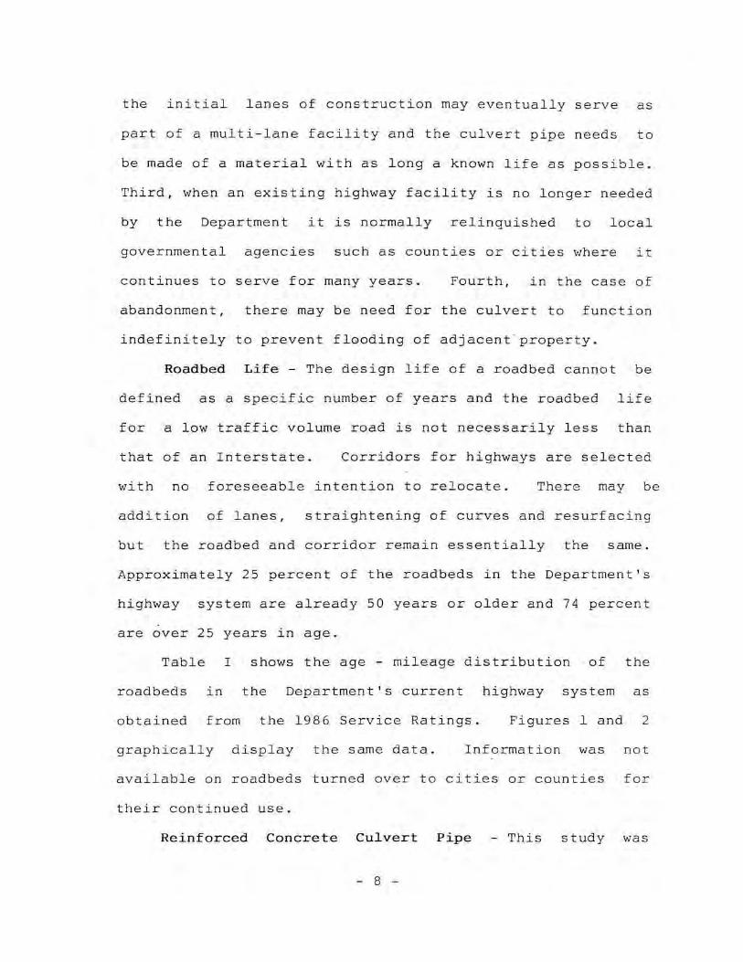
the initial lanes of construction may eventually serve as
part of a multi-lane facility and t he culvert pipe needs to
be made of a material with as long a known life as possible .
Third, when an existing highway facility is no longer needed
by the Depar t ment it is normally relinquished to local
governmental agencies such as counties or cities where it
continues to serve for many years . Fourth, in the case of
abandonment , there may be need for the culvert to function
indefinitely to prevent f100di n g of adjacent " property .
Roadbed Li fe - Th e design life of a roadbed cannot be
defined as a specific number of years and the roadbed life
for a low traffic volume road is not necessarily less than
that of an Interstate . Corridors for highways are selected
with no foreseeable intention to relocate . There may be
addition of lanes , straightening of curves and resurfacing
but the roadbed and corridor remain essentially the same .
Approximately 25 percent of the roadbeds in the Department ' s
highway system are already 50 years or older and 74 percent
are over 25 years in age .
Table I shows the age - mileage distribution of the
roadbeds in the Department ' s current highway system as
obtained from the 1986 Service Ratings . Figures land 2
graphically display the same data . Information vIas not
available on roadbeds turned over to cities or counties for
their continued use .
Reinfo r ced Concrete Culve r t Pi p e - This study was
- 8 -

INTERSTATE
YEAR MILES PERCENT
1921 1926 1931 1936 7.0 .3
'" 1941 7.6 .3 1946 9.' .4 1951 46. 8 2 . 0 1956 285 .7 12.3 1961 652 . 1 28.2 1966 1317 . 6 56 . 9 1971 1703.1 73.6 1976 2132.5 92.2 1981 2215.3 95.7 1986 2313.8 100 . 0
TABLE I
ROA08EOS CONSTRUCTED YEAR SHOWN OR EARLIER ANO STILL IN SERVICE
PRIMARY SUPPLEMENTARY.
HILES PERCENT HILES PERCENT
25.9 .3 86.2 .4 551. 7 7.2 334.9 1.4
1741.9 22.7 942, 6 3.8 3491.5 45.5 4967.1 20.2 3977.3 51.9 7099. 1 28.9 4215.2 55.0 7517.1 30.6 4489.4 58. 6 9944.7 40 . 5 4762.4 62.1 13972.0 56.8 5314.7 69 . 3 19432.1 79.1 59 13 . 7 77 . 1 22846.2 92.9 6489.2 84.6 23822 .3 %.9 7121.8 92. 9 24226.0 98.6 7404.3 96.6 244 18.2 99.3 7667.3 100.0 24579.5 100.0
TOTAL
MILES PERCENT
112. 1 .3 886.5 2 . 6
2684.5 7.8 8465.6 24.5
11084 .0 32.1 11741.6 34.0 14480.9 41.9 19020.1 55.0 25399.0 73.5 30077 . 5 87.0 32014 . 5 92.6 33480.3 %.9 34037.8 98.5 34560.5 100.0
"7
o ::r:: (I)
w O:::u <.,.- ':::-1., ?
WiY >-~ OL W-I 1--1 Or---. (f) .-J
0:::0 z I- <.1; 1J) cr:. Zw Ocr! C) <I;
w (f) a: 00 W m o -::( 0 0:::
\ "
0 0 0 0 ..".
\ '.
\ ~~ ,
~ '\
.::> 0 0 0 c :. 0 C'.) 0 r"r;, C~
S3llV,1
- 10 -
\
l \ \
"'",'+
\ 0 o 0 0 0 ~
1861
- ' 61 tiL
IL61
1961
1'061
9,,61
ItO I
9£61
1>:61
IZ61

f-7'
' ~ ~
;~ w U c.:: w CL
100
80
50
40
20
F:U,ilDBEDS COf\l STRUCTED YEAR c: H 11 \l\ / I\ I '..-! \J ~' .
OR E,ll,RLlER ,t,I~D STILL IN SERVICE , /_-X-~><- )( -~
I T /7'~~~»' ---+-
.. / /0"//
~ = ....,.
/ / 0 / /
/.;z("/ I ~ __ e--'"~_.£f// I
.~--e-- / / ~ . ....- I + / II i/
/ } ! , / ' ' ! ' I
.' / I
./ );,-_¥ / (lI ./ .
1/ l/ ;.
•
. I /
.1"/ / j ' / / o r\l""- r~..)( / * , 14
(\.J OJ ~
'D GI ,01 ~
Jr J 0> ~
u) <£)
'0 -d- -d-0> iJl ,'" ~ ~ ~
tL' ill lD (1) 01 U, ill (£1 I'- !,-. OJ OJ en r)";. 0> ,." OJ ", ,,, ,]') ~ - ~ ~ - ~ ~ ~
YE.A,R FIGURE 2
II' ITER
PRII·,~
supp

initiated to review the use and cost of zinc-coated
corrugated steel pipe . However, the economics and years of
satisfactory service expected from culverts by the
Department must necessarily include some reference to Rep as
it is the standard against which all other culverts are
currently measured .
Although they had been used since the mid 19th century
as sanitary sewers, irrigation pipes, and storm sewers , Rep
began to be used extensively as highway culverts with the
great e xpansio n of the nation ' s highway system, about 1915 .
Specific chemical and physical factors which can be
detrimental to concrete pipe are 1) acids,
chlorides, 4) freeze-thaw weathering, 5)
2) sulfates, 3)
abrasion, and 6)
structural failure . Locations in Missouri where these
conditions are severe enough to result in durability
problems for Rep used as highway culverts are rare .
Missouri does have acidic flow (low pH) in some areas
that ove r a long period of time does erode Rep .
of loss of service life is not yet known .
The degree
Sulfates, chlorides , and freeze-thaw weathering have
not been detrimental to Rep culverts on the Department ' s
highway system . Freeze-thaw action may be detrimental to
the culvert as mentioned later in this section, however, it
is not considered detrimental to the concrete material .
The abrasive action of aggregate particles over any
material causes erosion . However, in Rep abrasive wear is
- 12 -
minimal and is not a cause for concern on the Department ' s
highway system .
Reinforced concrete pipe used as highway culverts in
not exhibited failure of the concrete have Missouri
material. Any Rep installation rated as failed has been due
to disjointed pipe sections sometimes accompanied by
faulting and infiltration or exfil tration. This may be
caused by freeze -thaw action, high velocities at the outlet
causing undercutting of t~e pipe ,
settlement.
or differential fill
Proper compaction, modern day longer lengths of Rep
sections ,
failures .
and end protection for the culve rt have minimized
Installations on steep slopes or unstable soils
may, in special cases, necessitate the pipe sections being
mechanically tied together .
Research reports by some other State highway agencies
indicate that Rep can be expected to have a service life in
excess of 100 years .
a service life of
The Department ' s experience indicates
100+ years . Life predictions are
typically based on material condition and age of the pipe at
the time of inspection . Reinforced concrete pipe has been
extensively used as a highway culvert for approximately 75
years and since there is generally very little material
deterioration, the true life expectancy cannot yet be
accurately predicted . However , there is every reason to
believe that the useful life of Rep is much in excess of 100
- 13 -
years .
The Ohio Department of Tra nsportation in its Culvert
Durability Study , Report No. ODOT/L&D/82-1 dated
Jan uary 1 982 , developed service life p r ediction curves for
RCP based on pH of the flow and slope of the pipe . From
Figure 30 of that report , a n RCP o n a one percent slope with
a pH of 3 . 0 would have a service life of 80+ years . With a
pH of 7 . 0 a nd slope of one perce n t , the service life would
be expec t ed to be a lmost indefi n ite (mul t iple hundreds of
year s) .
In addition to having a lo ng s e rvice life, RCP can
ge nerally be reclaimed and reused if location o r size of an
installation needs to be changed .
Mode of Failure of RCP a nd CSP - These twa tvnes .. of
highway culvert are of totally dissimilar materials without
a commo n characteristic except they are both designed to
carry wat e r from one point to a nother . It should be noted
that the two types of culverts deteriorate and fail in
different ma nne r s .
As already stated, RCP is affected by certain
chemicals , freeze - thaw action , and physical or structural
disjointing . In Missouri , under the Department ' s current
design practices , Rep failures have been minimized . The
service life of RCP may be shortened by the low pH of
drainage in parts of the State but low pH is virtually the.
only environmental agent that affects RCP as a material .
- 14 -

Steel, as a material, and the coatings used for culvert
pipe are attacked by water and a variety of other
environmental agents . Corrugated steel pipe fails primarily
by rusting through the lower flow lin e section of the pipe
(invert) . The protective coating over the steel is removed
by water , abrasion , delamination, low or high pH drainage ,
or a variety of other reasons, allowing the base steel to be
exposed . The steel then rusts and eventually is penetrated , ,
nearly always in the invert . The causes and mechanics of
steel corrosion are not addressed in this study .
Review of Economics - Unit bid prices for Group I,
Group II, CMP and Class III RCP pipe installed by contract
for each of the past five years, 1982 through 1986, were
reviewed and a weighted average of the five years inclusive,
was calculated for each size .
The five year weighted costs per linear foot for Class
III RCP through 36 inch diameter are shown in Table II . The
corresponding values for CSP are shown i n Table III . Over
91 percent of all the Class III Rep and CSP installed by
contract in the five year period were 36 inch diameter or
less .
Costs of pipe over 36 inch diameter were not included
in the tables because of the limited u sage of those sizes .
With small quantities, consideration of the actual
installation conditions would greatly affect bid prices and
those conditions were not available for this study .
- 15 -

TABLE II
5 YEAR WEIGHTED COST PER LINEAR FOOT FOR
CLASS III REINFORCED CONCRETE PIPE
Diameter Total We ighted Weighted Average (inches) Linear Feet Cost Cost/Foot
12 91,648 $1,680 , 368 . 11 $18 . 34
15 81 , 648 $1,625,313 . 91 $19.91
18 105,759 $2,385 , 410.41 $22 . 56
21 12 , 353 $355,136 . 77 $28.75
24 58 , 054 $1 , 673 , 746 . 63 $28.83
27 2,928 $101,633.86 $34 . 71
30 33,815 $1,226 , 652 . 48 $36 . 28
33 16 $560 . 00 $35 . 00
36 31 , 772 $1,588,704 . 74 $50.00
Grand Total 417,993 $10,637,526 . 91 $25 . 45
NOTE: All original data obtained from 1982 through 1986 Unit Bid Prices issued by Missouri Highway and Transportation Department. Average low bid prices and annual quantity in linear feet were base figures.
- 16 -

TABLE I II
5 YEAR WEIGHTED COST PER LINEAR FOOT FOR
CORRUGATED STEEL PIPE (GRP I, GRP II & C.M.P . I
Diameter Total Weighted Weighted Average (inches) Linear Feet Cost Cos t /Foot
12 21,632 $325 , 635 . 18 $15 . 05
15 56 , 283 $848,670 . 25 $15 . 08
18 61 , 041 $1,034,100 . 02 $16 . 94
21 2,970 $56,108 . 25 $18.89
24 24 , 065 $49 4, 948 . 37 $20 . 57
27 0 0 0
30 9,468 $222 , 772 . 75 $23 . 53
33 0 0 0
36 8,703 5260,111. 52 $29 . 89
Grand To t al 184 , 162 $3 , 242 , 346 . 34 $17 . 61
NOTE : Al l original data obtained from 1982 through 1986 Unit Bid Prices is sued by Misso uri Highway and Transportatio n Department . Average low bid prices a nd annual quantity in linear feet were base figu r es.
- 17 -

The costs of the pipe are discussed here on a size
basis even though they are not hydraulically equivalent.
As expected, the initial installed cost of CSP was less
than Class III RCP in all sizes. In the sizes 12 through 36
inch diameter, the initial installed cost of CSP was 60 to
82 percent of the RCP with an average of 69 ' percent . A
similar calculation of all Class III RCP and CSP placed by
contract in 1986 showed a weighted average initial installed ,
cost of CSP to be 78 percent of RCP .
Standard economic formulas may be used to attempt to
equate the present worth of RCP and CSP . However, these
formulas require bidding of both types of pipes for the same
installation, hydraulically sizing each type of pipe,
assuming a service life for each type of culvert for that
location, and assuming an inflation factor and rate of
return on money for the analysis period . This type of
economic analysis could not be performed on the Department ' s
culverts because 1) the life of CSP is too variable
and would require a different analysis period for each
installation , 2) where pipe are bid as alternates, the
Department sizes the pipe on the basis of CSP which
generally oversizes the Rep, and 3) selecting an inflation
factor or interest rate is beyond the scope of this study .
Another problem with any economic prediction attempting
to equate the two types. of pipe is , it has to be assumed the
Department would have the money and manpower to replace the
- 18 -

culverts at time of failure . The Department neither loans
nor borrows money, therefore , all expenditures are on a ~pay
as you go " basis . The current financial and manpower
problems with replacement of CSP discussed elsewhere in this
report highlight this problem.
Regardless of the manipulation of data or economic
projections , the data previously collected by the Department
and the data collected to date in 1987, shows clearly that
CSP can be expected to be replaced from one to fo ur times
during the anticipated service life of RCP,
least 100 years .
which is at
The cost of repeated replacements cannot yet be
estimated with any degree of accuracy. The cost of
replacement of any pipe will be greater than the initial
installed cost because replacement requires c utting the
pavement surface , excavating the existing fill, and
generally more traffic control . The height of existing fill
above the culvert pipe and type of material in the fill
directly impact the replacement costs .
The project discussed later in this report which was
let only for the purpose of replacing CSP had a weighted
cost per linear foot approximately three times that of CSP
on projects where grading, paving, etc., are included.
Those costs do not reflect the cost and inconvenience to the
traveling public , the i mpaired roadway surface, and the
increased safety hazards involved in culvert failure .
- 19 -

Replaceme nt Or Re ha bilitatio n By Con trac t - Many of the
CSP and pipe arch (PA) installations are being re placed or
lined with a polyethylene pipe as a part of a contract
project . In 1986 , five contracts for rehabilitation or
replacement of CSP and PA were let . Four of these contracts
totaling 75 . 613 miles of roadway were primarily to resurface
the roadway . However, they included 14 , 253 linear feet of
CSP and PA to be replac ed or rehabilitated at an added cost
of $365,897 . 80 .
The fifth contract was let solely for the purpose of
replacing 1,384 linear feet o f CSP on 19 . 04 miles of r oadway
at a cost of $84 , 196 . 50 .
No attempt has been made to identify or quantify
contracts which only included replacement of a portion of
the CSP or PA and contracts let prior to 1986 are not
treated in this report .
There are currently at least 30 miles of roadway
scheduled for contract letting including replacement or
rehabilitation of CSP or PA .
Following is a brief description of the five contracts
let in 1986 which typify the type of work that can be
expected to i ncrease in the future .
i n Table IV .
The data is summarized
Project 9 - 5- 68 -270, Route 68 , Dent County was let
to contract in January 1986 . It was primarily a
widening and resurfacing project . The origina l CSP were
- 20 -

TABLE IV
REPLACEtlENT OR REHABIL lTATION BY CONTRACT
Weighted Total Cost of Age of Linear Cost of Cost/Ft . Lining or Total CSP CSP or PA Feet of Lining or of Lining ReplaCing CSP and PA Cost
Route Lined or CSP or PA Replacing or Replacing or PA and End To tal Cost of as Percent of and Replaced Lined or CSP or PA CSP or PA Sections Project Total Project County (yrs.) Replaced (S) (.1.> (S) (S) ( %)
68 Dent 52-54 2824 $ 53,549 . 50 $18.96 $ 63 , 371.50 S 730 , 744 . 61 9
8 Cra\~[or d 49 1786 $ 32,490.00 SlB.19 $ 49 , 140.00 $1,111,559.21 4
~ 19 Gasconade 49-56 4809 S122 , 427.00 S2S.46 S 99,099.00 $2 , 102 , 088 . 46 5
~
Itl2 Oregon 35-36 4834 $ 90 , 942.50 $18 . 81 $113 ,419. 30 S 925 , 133.63 12
T St. Charles 37-51 1384 $ 84 , 196 . 50 $60 . 84 $ 84,196 . 50 S 84,196.50 100

badly deteriorated with a high percentage of the pipe
having the invert totally rusted out . The original
pipe could not be extended due to its condition and
needed replacement . The CSP were originally installed
on this project in 1932 - 34. Two crossroad CSP had
been replaced prior to this project by the Department ' s
Maintenance personnel .
This project was 9.633 miles long and required
2 , 824 linear feet of pipe. The 2,824 linear feet of
CSP was placed at a cost of $53,549 . 50 or a weight ed
average cost of $18 . 96 per linear foot . Total cost of
the pipe installation ,
$63,371.50.
including end sections , was
In addition to the cost of total replacement by age
54 years , replacing the pipe created another problem .
It is very difficult to recompact a cut trench without
getting some settlement at a later date .
installations have now settled and
Most of these
there is a
depression in the roadway surface which is noticeable
to the traveling public .
Project F-8 - 1(9) Secs A and B, Route 8, Crawford
County was let to contract in June 1986. It was
primarily a resurfacing project . The project was
16.596 miles long . The CSP were originally installed
on this project in 1937 . No record of maintenance
replacement prior to 1986 was available .
- 22 -
This project required lining of 580 linear feet of
CSP and replacement of 1,206 feet of CSP . Lining was
performed by inse r ting a smooth wall polyethylene pipe
into the deteriorated esp . Lining of the 580 linear
feet was completed at a cost of $10 , 282.00 or a
weighted average cost of $17 . 73 per foot. The 1,206
linear feet of CSP was replaced at a cost of $22 , 208 . 00
or a weighted average cost of $18 . 41 per linear foot .
Total cost of the pipe lining and pipe installation ,
including end sections , was $49 , 140 . 00
Lining of the crossroad pipe provided an
alternative to closing the road to through traffic
where high fill or other co nditions made replacement
difficult. However , the plastic lin i ng reduces the
opening in the pipe and can only be used where its
hydra ulic capacity is adequate.
Projects F- 19-3(5) Secs A and B, F-19-2(9) Secs A
and B, and RS-68l(5), Route 19 , Gasconade County were
let to contract in November 1986 . They were primarily
resurfacing projects . These projects were 37 . 891 miles
long. The esp on these projects \.,rere originally
installed between 1930-37 . No record of replacement
prior to 1986 by Maintenance was available .
These projects required lining of 1 , 675 linear feet
of CSP at a cost pf $40,868.00 or a weighted average
cost of $24 . 40 per linear foot . It is interesting to
- 23 -
note the bid prices for these projects, which is the
second time polyethylene lining was specified,
increased from S16 . 00 to S23 . 00 per foot for 14 inch
diameter liner and from S22 . 00 to S34 . 00 per foot for
20 inch d iameter liners . Bid prices from more projects
would be requ ired to establis h the level of cost o f
polyethylene lin ing.
There was 3 , 134 linear feet of CSP replaced with
CSP on these projects at a cost of $81,559 . 00 or a
we ighted average cost of $26 . 02 per linear foot . Total
cost of the pipe installation,
was $99,099.00.
includ i ng end sections ,
Project RS-BHS - I098(2) Secs A and B, Route 142 ,
Oregon County was let to contract in November 1986 .
The project was primarily a resurfacing project . The
project was 11 . 493 miles long .
The project required replacement of all the CSP and
PA within the project limits . The CSP and PA were
originally installed in 19 50 and 1951 .
There wa s 4,834 linear feet of CSP and PA replaced
at a cost of $90,942 . 50 or a weighted average cost of
S18.81 per linear foot. Total cost of the pipe
installation , i nc lud ing end sections , was $113 , 419 . 30 .
Project 6-S-T-787, Route T , St . Charles-Warren
Counties was let to contract in July 1986 . This
project was let solely for the purpose of replacing
- 24 -
CSP . The project was 19 . 04 miles long .
The project required 1 , 384 linear feet of pipe at a
cost of S29,544 . 00 for the CSP and placement . However,
the total cost of the project including mobilization,
repair of the pavement, etc., have to be included in
the CSP cost since the project was solely foe
replacement of esp . The total cost of the project was
$84,196 . 50 or a weighted average cost per linear foot
foe the CSP of $60 . 84.
Replacement Or Rehabilitation By Maintenance Personnel
Maintenance of CSP is increasing in frequency and cost. The
CSP deteriorates at variable rates , however, the large
quantity of CSP placed between 1930 and 1965 have
deteriorated to the point where they are now requiring
replac~ment by Maintenance personnel or by contract .
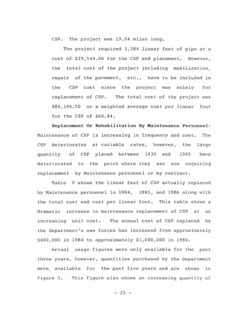
Table V shows the linear feet of CSP actually replaced
by Maintenance personnel in 1984 , 1985 , and 1986 along with
the total cost and cost per linear foot . This table shows a
dramatic increase in maintenance replacement of CSP at an
increasing unit cost . The an nual cost of CSP replaced by
the Department ' s ow n forces has increased from approximately
$400 , 000 in 1984 to approximately $1 , 000,000 in 1986 .
Actual u sage figures were only a vailable for the past
three years , however , quantities purchased by the Department
were available for the past five years and are shown in
Figure 3 . This figure also shows an increasing quantity of
- 25 -

TABLE V
CORRUGATED STEEL PIPE USED BY MAINTENANCE
Linear Feet of Price Per
Year CSP Used Linear Foot Total Cost
1984 16 , 902 $23 . 33 $394 , 32 4
1985 21 , 889 $23.74 $519 , 645
1986 37,583 $25.78 $968 , 890
- 26 -

,-, al (ll ~
0 W U) "" <1- (0
, OJ
::r:: ~
u et: ~
U) 0]
il c;, - n::: M
W ..;( OJ
W '" " il >- '" "<t H
<Xl "' il ~
<J) -~ et: W n ..... -.. <Xl ,-~ (ll
-1 -~ U
'" ( 0]
OJ ~
0 0 0 0 0 0 0 0 CJ CJ CJ CJ 0 0 CJ 0 CJ 0 a 0 0 0 0 0 0 'Co ", .". ", N -
133.::1 H-d3t-J Il - 27 -
CSP being purchased. A small , fairly constant quantity of
RCP is purchased each year.
The Department purchases and places approximately 1,500
linear feet of RCP per year . Most of the RCP is being used
in District 7 to replac e CSP that has failed due to acidic
drainage conditions.
In addition to the replacement of CSP, it is common
practice in some maintenance areas to rehabilitate CSP by
placing concrete in the invert where the metal has rusted
out . No cost data or number of pipe rehabilitated in this
manner are available at this time .
Culvert Replaceme nt Survey - In January of 1987, the
Division of Materials and Research, as a result of rising
concerns about culvert age and condition at the time of
replacement, r equested that the Districts gather and provide
certain information on crossroad pipe being replaced either
by Maintenance or by contract. The p u rpose of the survey is
to establish the condition and age of the culverts replaced.
The location , route , county, si ze and year of installation
are recorded and the information received from January 1,
1987 through May 1 2 , 1987, is attached as Appendix E.
An analysis of the information reveals that during this
period , based on 515 reports from Districts 1, 3 , 4, 5 , 6,
8 , 9 and 10 , the newest CSP replaced was 20 years of age and
the oldest was 59 years \ ... ith an average age of 46 . 6 years.
The data also indicates the CSP being replaced have partial
- 28 -
or totally mi s sing inverts. It does not reveal at what age
the inverts rusted o ut. This survey is an ongoing project
and information is still being compiled.
This survey also does not reveal the pipe with missing
inverts that are not immediately scheduled for replacement
due to availability of money and manpower .
reports it has a large percentage of CSP
One District
that have the
inverts missing but are not being replaced unti l the
workload and financial condition allow.
Research - As a portion of this report, a literature
search was performed. A list of the pUblications reviewed
is attached as Appendix F . Some quotes
publications are attached as Appendix G.
from selected
To briefly
summarize the results of these reports as o ne author states
in a 1984 report , " . . . it can be ant icipated tha t \ .. i th
proper care the primary and Interstate roadways could well
be in service 100 years from no w. " Durability problems
exist with all protective coatings now commonly used on
CSP and no nat ionally acceptable relationship betvJeen
culvert service life and corrosion parameters has been
developed.
Most researchers give a life e xpectancy of 100+ years to
reinforced concrete pipe . The Department ' s e xperiences
i ndicate a li fe expectancy of 100+ years for RCP. Loosening
and faulting of end joints was the primary type of failure .
Zinc - coated corruga t ed steel pipe has been around a long
- 29 -

time and has been the subject of many studies to determine
why it fails and to t ry to predict life expectancy in
differe n t enviro nments . Zi nc-coated steel is affected by
water , low pH ,
anaerob i c bacteria ,
low electrical resistivity of soils,
abrasive material, chlorides, sulfates ,
and many other factors . Predictions of life expectancy are
generally based on only part of the enviro nmental factors
and therefore the predictive procedures sho uld be considered
local i n nature. For i n stance , California uses pH and
electrical resistivity to predict life expectancy . This
method of trying to predict e xpected life has been the
subject of several States ' research and at least in the
reports rev i ewed , the States have not been able to make the
Californ ia method correlate \",ith actual experience . The pH
and electrical resistivity are important factors in setting
the stage for corrosion but are not the only factors and in
some cases are not considered sign ificant . Wisconsin found
bacteria to be a contributing factor in corrosion in 31
percent of the study sites . Maine and Ohio found little , if
any , correlation between electric resistivity and actual
condition . Utah found that approximately 14 pH tests were
necessary in the field to obtai n the true pH value within ±
1/2 unit . They also found the Department of Agriculture iso
maps to not be accurate enough to use . They recommended pH
be a lab test , not a field test . Neither California or
Wisconsin gave weight to abrasion which is co nsidered a
- 30 -

major factor by New York .
Coatings The Department has checked various types of
coatings over the years in an attempt to find a coating that
would increase the life expectancy of a corrugated steel
pipe to a point where it would approach that of RCP . To
obtain faster results, pipes with various coatings have been
placed in an area in District 7 known to have an acidic
runoff and in areas in Districts 8 and 9 with abrasive type
runoff .
The following discussion of various pipe coatings is a
general summary of Department observation a nd research
performed by others. In general, all the coatings have a
durability problem when exposed to abrasion.
"Epoxy Coated Corrugated Steel Pipe : B~oxy coatings
are affected by direct sunlight. The Department tested
epoxy coated CSP in an area with severe exposure (pH 3 . 0 ±
o . 3) . The acidic test section was abandoned as a failure
after five years of exposure . The invert was approximately
one-half gone and the top inside coating was brittle and
blistered with the deterioration beginning at the cut edges
of the individual sheets and at areas where exposed to
direct sunlight .
Bituminous Coated and Bituminous Coated a nd Paved CSP :
Bituminous
adhesion,
coated pipe
abrasion, and
is reported as
salts . Life
subject to poor
e xpectancy of the
coating ranges from 0 to 7 years. Bituminous coated and
- 31 -

paved is subject to the same problems as bituminous c oated
but if the paving extends far enough around the pipe more
life is gained - eight years according to Mai ne , at 30 years
accordi ng to New York 100 percent would have failed , and
Ohio ga ve a median life of 10+ years for paving that was
overtopped by flow . Kansas DOT has reported only 12 percent
of inside bituminou s coatings were good in three and seven
year old pipe .
The Depar t ment ' s i nves t iga t ion in 1965 concluded that
plain bituminous coating added t wo years of life and coating
and paving added about five years . The use of bituminous
coating or pavi ng was discontinued by the Departme nt .
Asbestos Bonded Bit uminous Coated and Paved Pipe : This
pipe was reported by Ohio DOT to be performing
satisfactorily after 12 years . This coating appears to be
the best of the coatings reported on esp .
to abrasion and high salt concentrations .
service life was made i n these reports .
Missouri has a test i nstallation of
It is susceptible
No prediction of
this type pipe
placed in 1974 in an acidic drainage area . The latest
inspection in December of 1986 shows the exterior coating is
deteriorating to t he e x te n t that small pieces are loose
enough to be pulled up from the asbestos . The asbestos is
now starting to debo nd from the pipe . Within four years
after i nstallation , the bituminous coating was severely
cracked , both inside and out , wit h the cracks varying in
- 32 -

width from minute to 1 /8 i nch or more . The invert itself is
apparently
amount of
starting to rust at the edges where
debonding has occurred. The small
a slight
amount of
debonding is apparently the r esult of abrasion or mechanical
damage . Asbesto s bonded coating is no longer available due
to enviro nme nta l control s .
Polymer Coated Corrugated Metal Pipe : New York DOT
reported polymer coatings as particu l a rly susceptible to
abrasive flow. Polymer coatings are immune to acidic flow
and when the coating is not broken or pe netrated it offers
protec tion to the CSP . It is report ed that problems due to
d elaminat io n d u ring fabri cati o n stil l e xist .
of service life were made .
No es tima tes
The Depar tme nt has o ne po l ymer tes t installation in a
non - a bras ive , acidic drainage . It is a r iveted pipe and at
age six months all rivets were gone from the invert and
approx imately 1/8 inch of the e xposed inlet edg e of the
me tal sheet was gone . Delamination start ed at that point .
After 15 years the deterioration has advanced a nd metal loss
and delamination increases with each annual inspection .
Current fabricating practice would probably be a lock seam
pipe to protect aga ins t e xposed rivets and cut edges .
Aluminum Coated Corrugated Steel Pipe :
se vera l aluminum coated culverts were installed ,
and reported in 1981 with re sults a s follows :
In 1952 ,
e valuated
"Overall performance of pipe c ulverts is based on small
- 33 -

sample size and test data havi ng wide variability which
may have con tributed to inco nsisten t fi ndings .
However , statistical a nalyses of measured a nd s ubjected
data as obtained f rom 28 year old pipe indicated
overal l performa nce of a luminum coated corrugated steel
pipe culverts was equal to or better than zinc-coated
corrugated steel pi pe culverts . "
The Departme n t has accepted this pipe as equal to
zinc - coated steel.
Alumi num- Zinc Alloy Coated Pipe : Bethlehem Steel
reports based on laboratory tests and limited field
i nstallations , s t ate t h is coating is equal to or better than
z i nc galva n izing . The coating is a mixture of approximately
55 percent aluminum and 45 percent zinc and appears to have
the same prob l ems as zi nc - coated pipe .
service life was reported .
No prediction of
Mi ssouri has not yet had this coating proposed for test
or use .
Survey Of Mos t Adjoining States - A telepho ne survey
of six of the ad join ing States was made to ascertain what
policy for culve r t type selection , culvert design life, and
roadbed design life is being used by those States . The
survey form as completed by t he telepho ne solicitor for each
of the States is shown in Appendix H. A summary of the
responses of each of the states, Arkansas , Illinois, Iowa ,
Kansas , Nebraska and Oklahoma , is as fo l lows :
- 3 4 -

Arkansas requires concrete for all c rossroad
drainage structures under all interstate and primary
routes and allows a n alternate of concrete and steel
under secondary routes , side roads, and entrances .
They do not have a set number of years as design life
expectancy
structures .
for either the roadbed or
They have trial installations of
drainage
polymer
coated steel and corrugated polyethylene pipe . The
FHWA in Arkansas has told them polymer coated steel
pipe is not an equal alternate to concrete.
Illinois requires concrete for all crossroad
drainage structures under high type pavement . They
allow an alternate of concrete or corrugated metal
under entrances, minor s ide road s and 10\'" type
pavements . They consider a roadbed design life to be
at least 50 years .
Iowa requires concrete for all crossroad drainage
structures under interstate and primary routes .
Secondary roads are a county responsibility and t he
counties generally follow Iowa DOT specifications a nd
procedures. Iowa allows an alternate of concrete or
corrugated steel under all e ntrances and secondary side
roads . They do not have a set number of years as
design life expectanc y for either the roadbed or
culverts .
Kan sas allows concrete a nd corrugated metal as
- 35 -

equal alternates for all drainage except only concrete
is specified for six counties in Southeast Kansas ,
locations where water stands in the culvert , or where
continuous flow is expected . They do not have a set
number of years for design life e xpectancy for either
the roadbed or drainage structures . Kansas found
bituminous coated pipe to have no significant benefit .
Nebraska requires concrete for all crossroad
drainage structures under interstate routes, all
concrete pavements , and all asphaltic concrete
pavements with a 20 year projected traffic of 800 ADT
or greater. Asphaltic concrete pavements in the · sand
hills " may have either concrete or steel pipe
regardless of traffic . Alternate materi a ls arc allowed
on entrances . They do not have a set number of years
as design life e xpectancy for eit her the roadbed or
culverts .
Oklahoma req u ires concrete for all crossroad
drainage structures . They allow either concrete or
corrugated metal for entrances. Oklahoma does not have
a set number of years as design life expectancy for
either the roadbed or culverts . In special
enviro nments , they may allow bituminous coated or
polymer coated steel pipe for entrances but not as
crossroad.
Only one of the adjoining States, Illinois, has a
- 36 -

design life for the roadbed which one could assume would
also apply to drainage structures . Kansas allows corrugated
metal to be used as crossroad drainage in more situations
than the other States. As stated by Nebraska in relation to
their "sand h ills , " corrosion of steel is not a problem in
granular well drained soils where corrosive drainage is not
present .
- 37 -

APPENDIX A
DESIGN POLICY
- 38 -

(
(
CHAPTER IX HYDRAULICS AND DRAINAGE
SECTION 9-10 NON-HYDRAULIC ASPECTS OF DRAINAGE DESIGN
9-) 0. \ GENERAL Drainage structures are located and designed /0 adequately handle runoff across improvements and to handle runoff from the improvement The location of cuJvcns i ~ covered in Chapter IV of this Manual The hydrauliC design of culverts and othel drainage faci lities is discussed in preceding sections In rhis section criteri~ peltaining to the selection of culver[ and storm sewer material and appurtenances are presented .
9- 10 2 lyr ES Permissible culvert types are concre le box, remforced concrete pipe, vitrified clay pipe , corrug3 red metal pipe. cor rugated aluminum alloy pipe, and cOHugared metal pipe-arch In general. there are IWO merhods of ~pecifying the permissible culvert Iypes dependent upon !he design traffic and rhe surface type . TIle first method is· to specify one particular culvert type and Ihe second melh od is ro specify a group of culvert Iypes as deH:·ibed in succeeding sections. The final selection of the structure type is based on requirements in the Standard Specifications, on good engineering judgmen ' , and economy with consideration of 5ervice and maintenance cosrs
(I) ROADWAYS WITH LESS mAN 400 ADT AND ENTRANCES, Permissible types of culvelts acceplable for use under all loadway~ with less than 400 ADT and all ent rances regardless of traffic or pavemen l surface type are concre te box, reinforced concrete pipe, corr ugated metal pipe, cOJlugated aluminum alloy pipe . and cOIJugared melal pipe·arch. Concrete box structures are considered for structures larger 'han 60 inches in diameter The most economical sr.ucture type may be used Corruga ted metal pipe arch suuctures in sizes 8 -S and larger are used where necessary because of limited allowable srruc ture height The T ype 8 ·1 through 8-4 corrugated melal pipe arch is nor acceptable A ballery of round pipe 0' $Ingle elliptical reinforced concrete pipe may be conside·ed in lieu of B· I through 8 -4 cOfluga ted melal pipe arch Twelve· and fift een ·rnch pipes ale nOI u~ed for cro~sroad culverts. cxcep r whe:e the use of an I S-inch pipe will creale an umightly or implaclicable drainage condllion lJeveted · ends ale specified for co rrugated melal pipes la.ger rhan 4S·inch dianleler COllugared metal pipe·arches are not beveled In general. Ihe bevel ohould nOI be flatter .han 2'1 nor should 'he skew exceed I S degrees If these controls are exceeded. special con$ideration i~ given to Ihe use of headwalls. dplap. 'or slope pavement fa stiffen the strUClure against uneven loading from the embankment and Ihe dynamic forces of the walel Proposed designs fOl .hese conditions are ~ubmlHed to Ihe ~bln Office for approval
- 39 -
In general. full circle pipes are specified on the plans by "Groups" These groups give the contraclor the permissive option of furnishing anyone or a comb ination of the ptpe Iypes within Ihe specified group One group of pipe (Group II) is provided for crossroad culvens for roads with design ADT of less !han 400 and for side drainage such as under enl/ances legaldless of the tramc Concrcte pipe is used fo r locations where high acidity or alkallllllY of soil s or waters or other cOHosive elements are plesent. The pennissi\'e pipe Iypes in Group II are (I) reinforced conClele. (2) corrugated melal. (3) cOHug:lIed aluminum aUoy When Group II pipe is specified hyd.aultc design computations should be based on corrugated meTal pipe In, special cases as described in a subsequent seclion "here one pipe type has a peculiar advan1age over olhc. pipe types, the particu lar pipe Type may be speciiied in lieu of $pecify ing groups
(2) ROADWAYS WITH 400 OR MORE ADT WITH SUR F ACE TYPE OTHER THAN ASPHALTIC CONCRETE OR PORTLAND CEJl.I ENT CONCRETE. Permissible types of culve ll s accepTable for use unde! roadway~ with 400 ADT or mOle with surface Iypc orher than asphaltic concrele O! portland cement conCICle arc concre te box. reinforced concrete pipe. cOllugated mel~~ pipe, and vjllified clay pipe (exII:! stlen gl h) Box culveils mspecified only when it is mOle economlC3l ro bUIld Ihe box than it is to prov.de an equivalenr p.pe cui vel •
in general. full circle pipes are spec. lied on Ihe plans by "Group" The gTOUp designation gives 'he COntraCfOl .he permi5sive opl ioll of furnishing anyone o r a combinaTion of Ihe pipe types wilhin Ihe specified group One group of pipes (Group [) i5 prOvided . The permissive pipe Iype~ in Group I a!e ( I) reinforced con'crete. (~) co. ruga red metal. (3) vi r" fied clay (exIra ~Irenglh) When Group I pipe is specified hydraulic design compura.ions should t.e based on corrugated mela] pipe In spec.al rases as described in a subsequenr secrion where one pipe Iype has a peculiar advantage over other pipe Iypes. the paflicular Iype may be ~pecified In lieu ot speCIfYing Ihe group 12" and 15" pipes ale nOI used e.'(cepl as outlers from drop inlets Elhplrcal reinforced concrele prpe may be used in special case~. u~ually fOl SIOfTn sewer ~. \\ltere necessary b\!cau$e or' Ijntil~d allowable "Tucture height
(3) ROADWAYS WITH SU RFACE TYPE OF ASPHALTiC CONC RETE O R PORTLAND CE~IENT CONC RETE PelmiSSlblc types 01 culveJls accepTable fOI use under roadways wrrh sur(ace type of a~ph a l"c concrere or ponland cemenl conClete are conClete bOx. and reinforced concrete 01 vlfllfled day pipe lextra stlength)
Rev J·16·81

The type of pipe to be used is specified on the plans The plans usually specify reinfOlced concrete pipe for all pipe strUClures excep t enHance pipe Villified day pipe is used only for se ..... ers · Box culvells are specified only when it is more economical to build the box than it is to provide an equivalent pipe culvetl
12" and 15" pipes are not used except as ou tlets from dlop inlets and in stonn sewer systems. The requirements fOl using reinforced conctete pipe or vitdfied day pipe for structures may be waived if conditions warrant. such as poor st ructute fou ndation conditi ons. high fi lls. simplificarion of handling traffic. etc Corrugated metal pipe is specified fOl rhe portion of med ian out le t pipes outside the edge of pavement ..... here such pipes are located on high fiUs requiring a break in nowline grade Details fOl such Installations ale illustrated on Figure 9-10 I Corrugated metal pipe may also be specified 10 drain dlop inlels in to crosstoad drainage structures when such installat ion necessitates a steep flowline grade and when the pipe will not extend under the pavement.
(4) ENTRANCE PIPE Permiss1ble Iypes of pipe used fo r enHances are d~ribed in Section 9-10 2(1) and ale usually specified by respective group Flared end sections ale not lequired .
(5) SIDE ROAD APPROACH STRUCTURES Permissible rype~ of st ructures acceptable fOI use under side road approaches ar e dependent on traffic volume 0 1
pavemenr surface type as described in Sec 9· 10.2(1) thru Sec 9·10 2(3) Flared end sections are required where the side road design liafflc exceeds 750 vpd
(6) OUTER ROADWAY DRA fNAGE STRUCTURES. Permi ssible types of culvert pipe acceptable for use under outer roadways ate dependent on tr affic volu me o r pavement surface type as described in Sec . 9-102(1) thru Sec 9-10.2(1) excep t that con rinuous drainage stlUctures extending under outer road ..... ays :ue designed to the same standard as required for Ihe portion of The slI ucture under the main roadway Since a conrin uous drainage structure usuall y increases the standard fo r the portion under the outer roadway. it is usually mOle economical to use independent structures Where contlnuous SlTuc tures ale used. the runoff between the outer roadway and lhe main roadway is usually carried into Ihe clOssroad structure by drop inleTS and p ipe Whete the crossload structure is a relatively small pipe. the drop inlet is consl1ucted in the crossroad structure
Flared end sections ale specified at both ends of pipe stiUclures 66" or le~5 in diameter regard less o f the pipe Iype In special cases where low clearance exists and rhe structure ic essentially at rig/II angles on loads with less than <l00 ADT . pipe alches with thled end sec tions may be speCified
- 40 -
(7) MULTIPLE OPENING INSTALLATIONS Multiple openin g structures. erlher boxes or pipe,. ale used only as required whe re the allowable st ructure height is restricted Where multiple pipes are constructed. the pipes ate separated by 3 distance of 1/2 their OUTSIde dIameter. or a minimum of one foot. whichever is greater Multiple box SU UCIUles reqUire special deSigns by the DiviSion of Bridges Whe re such designs 3re reqUired. the DiviSIOn of Bridges is furni shed with the culvert section. grade across the st ructute, typical sectIon. and any othe r necessary information FOI dtainage ateas 1.000 acres and und er which requi re a structure destgned by the Bridge Division (multiple box, etc). Ihe Disltrct shall also make the necessary_ anal ysis and provide 10 rhe Bridge DiviSIOn the drainage area. The mag.nitude of rhe discharge. frequency. and \lcsign highwaler for placement on the plans fo r each structure
(8) INSTALLATIONS FOR SPECIAL SITU ATIONS FOI installations on a project which normally would require Group I. or II. pipe options (Sec Secliom 9- 10 J(I) and Q 10 2(2). special conoitions may exist which would Justify Ihe specifying of a single pipe type Justification fo r the selec tion of:l. single pipe type includes, but is not limHeo to. unstable foundation. high embankmenTS. high erosrve forces. 01 other peJlinem reasons When anyone Of a combinal ion oj these factors exist. the culveJl pipe type best sui led 10 resist such destructive forces i~ seleCTed and specified When a single pipe Iype is specified. In heu of a group . the leasom fOI such se lection ale induded in the Ic. tter of tlansmillal of the plans
(9) STORM SEWERS PermiSSible srorm sewer types are conctete box. tctnfOlced COnCtCle pipe and vitlifred clay pipe (extra suength). Stolm sewers are considered to be special insfallations and the paJlicular type of stlucWre necessalY for [he pa rticular !ocallon is selected and specified on rhe plans
9·10 3 BOX CULV ERTS
(I) BOX CU LVERT STAN DARD PLA NS Box culver t standard plans fot all load ways are tabulated in the "Table of Gellera! Design Oat:!" in Chapter IV
(2) BOX CU LVERT SHAPE The most economical bmr culvert shape is approximately square. or a span slightly less Ihan the height Hydraulic factors will conllol the required shape of rhe box culvert Box culve" sizes 3le indicaled on the plans as span .'( height
(1) SMA LL BOX CULVERTS Small box culvellS based on DraW ing 701 10 of the Standald Plans ale used only 3S required 10 meet unusual conditions since p'pe structures aTe usually more eCOnOJlllcai
Rev 4-16·81

(
(
9· 10 <1 PIPE HEADWALLS Type S pipe headwalls may be used in lieu of drop inlets for med ian pipes fo r medians 60-feet wide or wider. Details for Type S pipe headwalls are snown on Drawing 604 as, of the Standard Plans
9-10.5 FLARED END SECTIONS. Flared end sections are required for crossroad pipe structures where the design traffic exceeds 750 vpd as tabulated in Section 4-04, "Basic Design Data " Drawing 732 00 of the Standard Plans shows details for flared end sections Whclc flared end sections are used on skewed pipe, the section is placed on the same line as the pipe , and the fill slope is warped 10 fit.
9-106 FLOODGATES Floodgates arc specified fOI
rhe outlet ends of pipes where required to prevent fl oodwalcr [10m backing th rough the pipe. Type I flO Odgates [or mounting on concrete structu res wiJl requi re a special (rem Numbel and special provision Type' 2 flood gates shall be installed on corrugated metal pipe . The hydraulic head is to be specified on the plans If the hydraulic head is not specified on the plans. Ihe heighl of fill above the pipe will be considered Ihe hydlaul ic head. The number of fl oodgates i~ listed on the plans in accordance with pipe sizes
9.10.7 REINFORCED CONCRETE P IPES.
(I) CLASSES OF STRENGTH. Reinfo'ced conc rete pipe is available and is !'pecified on the plans as anyone of five classes designaled as Class I, I/. III, IV, or V Class V pipe is the sirongest design
(2) USE OF VARIOUS CLASSES. aan I and Class II reinforced conclere pi pe is used only for sewers in trenches outside loadbed and streel limits . Class I pipe is provided in 60" to IDS·· diamere·~. inclUSIVe, and is used in trenches ten fee l or less in depth Class II pipe is provided in sizes from 12" to t08" diametelS. inclUSIve . and is used in trenches 15 feet or less in deplh Deepel Trenches reqUire Class III. IV. 01 V pipe Class III , IV. or V pipe is used fOI aU olher drainage st luctures and are provided In ~i zes r,om 12" to 108" diameters. inclusive
0) SE LECTION OF PIPE CLASS AND BEDDING TIle seleCTIOn of a proper class and beddi ng fOI leinforced concrele pipe :n a specific location involves a de tailed ~lUdy and analysis of the cond itions aT the culver t loc:1Iion. and a comparative cost analysis of lhe various combinations which will sat isfy The requirements for the particular inSTallaTion Usually more than one combinalion will meel The requiTement s When the culvell pipe is specifie d on The plans by Group I. or 11. Ihe con rractor ~elec l s fhe class of pipe and class of bedding
- 41
commensurate wllh Ih e Ins'.allation condi1! ons When lein fo . ced conclete culvel1 pipe is specified on the plans. the mOST economical combination of class of pipe and class of bedding is selected. with consideiallon gIven 10 selvice and minim izing the numbel of bid items The Older of p,e feTence for using the five classes of reinfo rced conClete pipe is (I ) Class I, (2) Class II. (3) Class II I. (4) Class IV. and (5) Class V The ordel of preference for using the fO Ul classes o f bedding is (I) Class C. (2) Class B. (3) Class 81 . and (4) Class A The proper proceduTe is to use Ihe lowest class of pipe in combination WiTh the lowest possible class of bedding consislenl with the lequirements of the pa;Ticular instal lation
(4) SPECI FYI NG PIPE CLASS AND BEDDI NG ON PLANS When reinforced concreT e pipe is pe'mined as an optIon by Specifying Gr oup I , Of II . culvell pipe on the plans. neilher The class of .emfOJced concrete pipe nor the class of beddin~ is specified When reinforced conc rete pipe IS specified on the plans. the clas~ of reinforced concrete pipe is specified and Ihe class of bedding is specified if a bedding other Than Class C is used
(5) PA YMENT FOR BEDDING When reinfOiced concrete pipe is pe rmitted as an opuon by specifymg G roup I. or " . culvert pipe on Ihe pl:Jns. payment for special bedding is not ind uded and Ihe Class 3 Excavation includes only that quanllly necessary fo r a mrnimum installation Wher e o1:elfill herghts are 34 feel or mo'e . nei Ther the excavaTion required fo r impetfect rrench and conclete cradle nor The concrete ror the cradle will be al lowed fOI paymenT When leinfotced conclete pipe is specified on rhe plans. Ihe Class 3 Excavarlon 15 compureel TO include the excavation fo r the specrfred beading Payment for all cl asses of bedding is incl uded in The bid pnce fo r Class 3 Ex cavation . except Class A bedd in~ whe'e seP <l:,ate payment is made for The concre fe
9-10 8 FILL SETTLH.·tEN TS FlU settlements can sell ously a.ffect concrete box st luct ure s by opening joi nts and cracks sufficiently to allow rhe frll around the culve rt /0 infiltrate into Ihe cul ven . Ihe.eby Cleating voids which can cause Ihe wadbea TO fai l [n aleas subjec i TO lal ge ~ e "lemenls . other ~rruc tur e Iypes a:e co nside!ed 01 Ihe box culvert is deSIgned 10 wllhstand rhe serrlement . This requiI es special box culvefl de~igns and whe re box culverts are to be so designeo . the Division of B,idges is furnished wjlh full info . marion. including culvert Sec tions. gl3des. and an licipaled <;(! \Tlemen t . Box culverts with special colla rs ar ound joinTS ha ve been successfully designed and used in 31eas subjec r to lar bre fr ll se rr lemen ts Since such s tructures a'c expeml '·c. rt i~ someTimes mOle economIcal 10 usc o' her ~Iructu'e Iypes such as nexible pIpe
g · lO g CAi\'lBER IN CULVERTS (ambel as used in cuJvefl design is deiined as Ihe d' ~tance the ~'enllat po rilon
Rev ':"16,81

of crossroad structures i~ constructed above final flow-line grade to compens:lIc fo r anticipated settlemenl. Typical details for cambering culverts are shown on Drawing 726 .30 of the Standald Plans A structure designed with proper camber will se ttle to near flowline grade and elevation when it reaches final seulement. All culverts, except those on non·yielding founda ti ons, are cambered at a minimum rate of 001 foot per foot of overftll Cambers of 0 I foot or less are not shown on plans. Where the fin settlement is known , culverts are designed with a camber equal to the an ticipated se ttlement. The camber is shown on the culvert section at the roadbed shoulders by amount and fl ow-Hne elevation as illustrated in Chapter IV.
9·10. 10 CULVERT EXTENSIONS. AU culvert exte nsions. both boxes and pipes. are extended with st lUctures mee ting current design requirements and standards, regardless of the type of standard of the existing structure. Pipe collars as detailed on Drawing 60440 of the Standard Plans are used to connect different types of pipe, and conc rete pipe to concrete pipe Box culverts are extended in accordance with details shown on Drawing 7033S of Ihe Standard Plans and Figure 9- 10.2 Additional Hils on existing box culverts m3Y require a structural analysis of the existing structure by the Division of Bridges If so" lhe Division of Bridges is fu rnished a print of the completed culvert sec tion and the st andard to which the existing slmcture waS designed. if known, for their use in making the analysis
9- )0.1 I OVERFILL HEIGHTS
(1) MINIMUM FILL HEIGHTS. The minimum allowable fill or cover for all structu res is one foot at the shoulder line , with the following excepti ons: The minimum fill for structural-plate pipe structures is labulated in Figure 9-107 In addition, the minimum clearance from the top of st ructures to the bottom of bases is six inches. Excep tions are special box culverts designed to carry traffic on the top slab. Where low type surfaces are used. the minimum fi ll at the shoulder on the inside of super-eleva led curves is 18 inches Minimum fiU heights for vitrified cl ay pipe (ext ra slJ ength) are 4 feet for Ihe 8" through 21" diameters and 3 feet for the 24" through 36" diameters Overfill heights which are less than Ihose indicated as allowable for anyone pipe Iype are not considered as justification fo r the el imination of specifying pipe types by "Groups" provided o ther criteria are satisfactory .
(2) DESIGN FILL HEIGHTS. ]f any quest ion developes regarding the fin heigh ts 10 be used, and where the fil l heigh t is between values labulated for design, the design fill height is laken to the next incremen t requiring the higher design Pipe culverts are designed th roughout
- 42 -
the ir length for the maximum design condilion except in Ihe case of structural plate pipe Box culver t extension s and box cu lverts in secti ons are designed for the hei~1 of fill over individual sections in accord ance wilh details shown on Figu re 9-102 Box culverts are designed for all fill heighTS Design fill heigh ts for al l pipe culverts specified by "Groups" are shown on th e "B" shee ts The allowable overfill heights for cOllugated meta] pipe-a rches and structural plate pipes are tabulated in Figures 9· \0 6 and 9-10 7, respectively These overfill heights Indicate both a minimum and a maximum . nelthel of which should be exceeded The column headed "STandald" under gage fOl pipe-arches in Figure 9· 10 6 lefels 10 Ihe gage le'luhed for the particular structure by the Standard Specifications If overfill heights exceed the lange shown . a diffelent gage may be necessary and a special design is requested ftOm the Main Office A special deSign is also le'lueSled fOI pipe-arches of a size nOI liSTed in FigUie 9 10 6 If a different gage is necessary, the plans specify fhe gage required Where overfill helghrs are glealel than shown in the figure , conside ration should be given 10 :ound pipe The gage for structural plate pipe is speci fIed on the plans and may be changed thr oughout the lengrh of the sTructUie. where economically feasible. depe nden l on the fill heights in accordance with Figure Q·]O 7
(3) MAXIMUM FILL HEIGHTS
(a) BOX CU LVERTS If The fI ll height excee.:ls the values tabulaled on the Standard Plan s. special deSIgn s ale • required. In such cases, the Dist rict furnishes the Di\'ISIOn
of Bridges with one copy of FOTm SP·8 and one pTinr showing the completed culvert seel ion A form is submitted fo r each section of the culvell requinng special design . The Division of Bridges adds the design da ta to the form and '(elurns it to the Di str ict for thei r use in computing quantities An example of a com pie led Form SP·8 is shown on Figu re 9·10 3 (see also Chapter IV)
(b) PIPES. Design ove rfIll hei gh ts which al e in excess of those indicated as allo ..... able fOI anyone pipe type are not considered as juslification fOI the eliminalLon of specifying pipe types by "Groups" provided o ther criteria are sat isfactOiY
9- 10.12 CU LVERT GRADES (iOssroad drainage structures are usually placed on a glade eljual 10 Ihe natural ditch grade or the di tch grade 10 which the culvert is being placed ContlOlllng grades for stolm and saniTary sewers are given in preceding sections ErOSIon may be a problem at the outlet end of culvetls on Sleep glades. which some limes can be leduced by breaking the grade through the culve rt Grade breaks can be used TO reduce stlucture excavation Drop stlUc lU res can be used at Ihe inlet end of cu lverts TO reduce The grade Through The culve rt Drop structure s ar e used with discreITon because
Rev 4·16·8 1

of the ponding upstream. and because of the unstable condition that may be created by the ponding. The grade for pipes for median drop inlets is broken in accordance with the requirements and details illustrated on Figure 9· 10.1.
9·10.13 CULVERT LENGTHS
(I) GENERAL. Culvert lengths are detennined graphically by scaling from the culvert sections. The lengths are obtained by intersection of the structure with slope lines as shown on the culvert Standard Plans, and as described in the following sections. Precise lengths are not computed. In questionable cases a longer length is used. Skewed slopes used for culvert sections are shown on Figure 9·10.4. Intennedi3te values are interpolated.
(2) BOX CULVERTS. The length of box culvertS is the distance between headwalls, and is scaled to the next higher foot. Headwalls are designed sloped along the flow-line grade. Box culverts over 75 feet long, and extensions, are built in sections, and the sections are designed to meet the requirements shown on Figure 9-10.2. The minimum length fo r box culverts is two feet greater than the roadbed width measured normal to the centerline of the roadbed.
(3) PlPES. The length of pipe culverts with headwalls is two feet longer than the distance between headwalls. Pipe headwalls are designed on a flat grade. regardless of the grade of the pipe. The length of pipe culverts not beveled and without headwalls is the distance between the slope lines at the flow line. Metal pipe lengths are scaled to the next higher even foot. Other pipe lengths are scaled to the next higher foo t. The length of metal pipes with beveled ends is two feet longer than the
- 43 -
distance between the intersection of the slope lines and the centerline of the pipe scaled to the next higher even foot. Pipe bends and special connections are not listed as a pay item on the plans. The plans do include notes to the effect that such items are required and that their costs are included in other items. The plans include , usually on the culvert sections, sufficient dimensions and detail to fabricate pipe with bends or special connections.
9·10.14 CLASS 3 EXCAVATION. Class 3 Excavation is measured and computed in accordance with detail s shown in Figure 9·10.5, supplemented by Figure 9-10.1 and applicable Standard Plans. Since the Standard Specifications provide for lhe payment of plan quantities of Class 3 Excavation. care is exercised in computing the quantities. Each structure is checked carefully on the field checks, and appropriate notes are made to insure that the quantities are as accurate as possible. A common error is to compute only the quantities below the ditch flow line where the struct ure approaches or exceeds the width of the natural ditch. Class 3 Excavation is computed to include the removal of only that part of an ex.isting structure within the normal limits of Class 3 Excavation The plans include a removal item for the removal of the portion or portions of ex.isting structures outside the nonnal limits of Class 3 Excavation. Care is exercised to avoid duplicate payment fo r the same excavation. such as computing Class 3 Excavation where channel change quantities or roadway excavation has been computed .
9-10.15 CONNECTIONS. The plans provide for connecting new structures to existing structures. and connecting different types of new structures . The plans do not include an item for the connection of pipes to existing manholes, box culverts, drop inlets, or sewer pipes. The plans do include the pipe collar item for con nec ting different types of pipe or different sizes of pipes. Details for pipe collars are shown on Drawing 604.40, of the Standard Plans.
Rev. 4-16·81

APPENDIX B
ROADBED LIFE
- 44 -

a. .? .:::. ";":\, !" .... c ~ r> ,\ ' ~ "r."'I ";"OX I ~ v V ' ,n . ,,'{ "l' : "
n q APq 14. l QR 7 t h . "
HPfl l);\FA n A~~ TS ~ n A~q F~ HA S n F ~ ~ f~ PLA: E ! T l~ ~ S T ~u r~ l~ " ~
S YS T F!-A __ L.F"IGII-J~·_~c~n,,", u .. t:; ~ T. __ _ ____ _ TMTS --~ 6 .. QQ1 C')NST 19 16 ,,\ir: PPTntt T NTS 7.<;73 [ O,,"," T 1'1 1. , ANf" PR!,nQ
! N.r'L Q .. 4 00 __ ::lJ"t'5 : . L94 f> . . ~~ . tH'I f) :> r "-'T S 46 . Al1 CI1 "'I ~ T lQC;l A",n pprn rJ
I~T~ ?~ ~ . ~ ~ 4 [~ ~S T l O~~ AN~ ~pr~Q
I'I"!"S . ____ 65 2.~_1~ . _i fl ~C; "" _lO fd AN" nOT m'
TNT<; 1 . ~t7.64 0 C O ~ $ T 19,c,6 A /I.li' PRTOP
PIT S ,!.7n 1.1 0 ~ CONST LO"' 1 AN D D~rl)"
p,!"!"$ 2 . 1JZ .. ~..3.Z CQ~'S T_ .l9 1 t> A~~ ~D. IIJ P
!~T S ??1 ~ . 1?~ cn~sT t oa l !i ~Jr'l oprno I NT S ? ~1' . "" ~? ~ ' ~I~ T , 0Q A .A " '"'
too r rR
PRY PRY PRL PP T oU! P P.T P RT po , PPT 0 F'~
PPI PP T P RI POI
"lIP p S l)Po S IloD supp sup p S OP 0 '; I}P O
S 1)0 0
S IIPD $ ' !PP $ 1100
SUP p S I) DD
SIIPD
?~ . n ' 6 C ~~ST 192 1 4 ~~ oRIOP 5~ 1 . 6h 4 cnNST tq?b 4N~ P RIOQ
.1 • 7 .4-L ... 8 9Z. __ CQ ~S; _!..cD.L ~.N..J)_ ?,_ p !nR
1 , 4 Q l.4 7e cn ~S T lq J6 d\in PAroo ' , Q7"' . '~ O r O ~ST 19 4 1 l~' pp r00 (· , 2)~ . T'i4 C C "IST 1'14 A ANn OP! (tR 4 .. 4 Rq-:-i o ·t - - r: "'';'15 ~q i; l~ ~ "J; - P p tr)R. 4. 767 .44 n CONS T l q~h A~n oPTOR ~ ., ] t4 ... 691_ C D' J_ST .. !9ft l I\"JI) oQ!OQ "' , c'11 . 6 .... (,. ~n " S T l ?"~ 1'.\11') DP!f)Q 6 ,4 0Q -l .tl:") en "IST 107 1 ,\N f) P R TOR' 7.\ 71. 7 95 r:: rHJ S T \9"'6 ~"J"I Pp 1' f"!Q
·7 .-404·. 7"f')~-·C'1""'S·T -!. 9Bt ·-AW) -op t r)Q: 7 . 6~ 7. 7A6 CO NST 1?~6 AN~ 0 Q! r)R
.~ f. . • 7:'1 r: ml ST 1 9 2 1 HI'"'I oQT f) °.
3)4 . ~7Q CO NST 1<') Z6 !'. 'W of;!fn~
__ ~~? ~ C;?~ r.rl ~<;; T J q~! ,0, "' j pq r I)D ~
It . Of.,7 .1 2fl en NS T 'Q~ b AN':' OP!OR 7 , OOQ . t ? t. cn"' 'i T 1 q4 1 " "J1) C1 Q. ! f"J~
7 , "'_17. 0 "!2 CON<; ....... 1. q.~6~. A ~n p~r l)Q.
Q . '7 l.4 . 7"?9 Cntll o;; T ! 9'lt A ~I" op I O~
11 . "71 . 0Q 5 r rHJ<:;T tQ")6 <\ N"'1 PO Tf"J" .1 Q, !--~~. ~.! (, <; _~ ~ "j)~T 1 9"-.1 .. J\ 'l ~1 o~r f) q
2 2 . ~4" . 2 0 4 CONST l W,f, ~ ~ry OR!nO
7 "'. 317. . 2'<; 4 C n ~~ 'S T 197 1 A " '~ pO IOQ
L~ . 2:26 . 02:0 CD"} ')T 1 976 .. ,\ ,}I"'I oqrO R. 2 4,~JR.~ 'l 't crl~ST lOAl II"-!"! OR!r.R "1 •• <;""t'J • (. c; ., r '1 'J~'" lflP ') !I. " 0 p DTn::>
_ A .e::: _

APPENDIX C
PIPE QUANTITIES USED BY MAINTENANCE
•
- 46 -

n.' _______ 1 t,_q -!, ~ ___ . __ .. __ 4 . ,, ____ . __ . _________ ,
"' ") 0 °'1 7 . ,", 7t.. . n
·1 t. ') . 1") .... . 0
n·, ., ~, ~ .. (.' e, • ,O ? . J ~
n ? 4- '1 " . r'l 1 , " 11. n
(F! I , "i!.<: · 0
0., l • "l l. , . 0
I n "' . ?! 1 . 0
" ... q ~7 . ::
" I
0"
", :v·
OQ
t il 1 • • 1"'\ <":: . "" ------'-----'-------_._ . ....
47

'" '1 1. , • elf''' , r
." (';" , • ("1 L,r • I'.
"' 01 < , 1 "' ? • • )
- -- .. ------- ----------.--- -
... f". ~(:' O"' <) .... ~ T~ / , '17 ! C' -'
v ;:~'tl r.r <:: ~ " I -J. <; 1 9 *
1,) (' <::. 0
:., <4 4", .. ')
, • ' l 1 .:; .. '
-----_.-B6 t n '. '>4 ,"1 . '1 ---'-----------------_._ ._--------
Pipe quantities used by Maintenance in the years 1984, 1985 and 1986 .
*Object Code 517 is eMP . Object Code 518 is Rep.
- 48 -
APPENDIX D
PIPES REPLACED OR REHABILITATED BY CONTRACT
- 49 -

ITEMIZED PROPOSAL 9 - 5-68-210 RTE 6 8 CO DENT
l I UNIT PRICE ITEM
UNIT QUANTITY
I
18 IN. PIPE CULV ER T GROUP I
125- J l. H I . OQZ 18 250 19929 ~OO
, ''" , <N "
24 I N . PIPE CI,.LVEil. T GPOUP I
12 5- i>1 .2( 510 23 580 121)25 ~80
, , '" " 1 '0 ' N . P ' P< <UL V,"T ,
12<;-0 1. 3C 156 " 100 4 519 ~.u
po",." I ,. 1'1 . t> ' P1:: Cl:l ... E~ T GROUP I
, 12 5 - 0 1 . 3~ ' 0 31 ,., 151 5 f oO
I PER U N FT
I " " . PIPE " OFO" "
~OO , 1 ~5-02 . l~ " 0 15 000 110100
U ' " I " 'N . 'fPE RT " l" , 7Z5 - 1)2 . U .. 18 2" '39
'" ' '" " 19 I~J . FLjQEC ENO S;:CTlCN
1) 2 - -10 . l ~ ,,' 5400 ~OO
,
0'" ,
I " ". 'L"" " " 01'0. ! 132 - (10 . 2~ 2b ., 000 2 '.>22 . 00
'0, "c, , 30 I N . Flt,U;:O "' · !O ,
I 9
1
1:i? - OO . ) : a '" 000 1400 . JO
I I
,0, " c> I I ,
- 50 -

ITEMIZED PROPOSAL
i I ITEM I DESCRIPTION UNIT
QUANTITY
36 IN. FUR ED END seC TI ON
1 732-00.36 Z
. '00 """ TYP E , .w ULCH
Z 80Z - 30 .00 ZI
DIOQ oI.CIl F
S EEe I NG
3 805 -1 0 . VO Zl
D"" ACJP:
• TOTAL FOR PROJEC T
I
I I
- 51 -
I I ,
<1-5-68-270 RTE 68 CO OENT
UNIT PRI CE i DOll.AIIS CTS :
250 000 1 I ,
675.000
6" 000
I I
I I I , I
I
AMOUNT OO~V.AS cr'
'500 loo
14115 00
IItl1S 00
130';4 f 61
,
I
, ! I

ITEMIZED PROPOSAL
~ I ITEM I DESCRIPTION
QUANTITY I UN IT
TVP !: In Od J iOC r ~A<lJ( t::<
I 61b- l 0 . 41 60
. 1>1;11. EA'''' . " !),H LIlATI ON . , 6 11 - 10.00 , . P;': R L U~P SU Jot
TEHPORH.Y °A\'E~E 'lr JII "'RKI~G
, 622-1 ::1 . 1]0 •• l
PER ~[L i
Al TEftNA Te A. " ". INS EftflQN LIN !;;!;
; 700 - QQ . 14 ' 93
PER L t ~I .. t= T .. ,\LT E;l. N.lr e a. L {N I NG FO~ " "'II. CUL VE:H P IP E , 1 00- <JQ . 'H 19'
P!: R LIN . FT.
" r N. P I P", CULV<:R G~')UP I
6 72~ -C l . li '" PER lI Ii FT
I" : f'l. ;> f PF. CUt V Eil: r GR!.JUP t 1
1 nS - 02 . 1 >} , ' p;:'!. l {I'll "
,
I" I "; .. F l,l, .~EO ~ '; ;! ,) = 1.. rr ,,;:.
, l1.'! - O"l . l ~ " 'EO :: 0\(1<4 I
TV;>,,! 2 " ry" . ) "Ul CH
1 5 . 0
PER "' COlE
- 52 -
I , , ,
, I I
i !
,
F- !l-ll q , S=C ,\ jHe a cn CR,\ .... F ORO
UNIT PRICE , AMOUNT
OO~l"~S I crs , OOllAI'IS cr~
I , 11 2S0 I 67' jOO
I , I I I
l ~.:)oo.OI)O l l COOO:OO
I I !
1<' 51000 I
f-
1l!> 2 50
I I
I I
1 6 . DOll )018 . 00
I ,
Loa 1 I
1!l1000
, I
<'>2!oIo . JO
I , I
2'Z ~ OOI) ')24 . ,),)
I
I ) ' '' ~ OOO " 2')0 . :') ·)
I , I

ITEMIZED PROPOSAL
~ I 'TEM
! DESCRIPTION OUANTlTV , I I UNIT
P1l: [M E LI OU [ e A$;>HAlT " " o. 'C )0
I 10 0 3-11).10 )90
P!: ;l. ,> ALL ')N
F IEL D LAB OR AT OR I ES
z bO t-l 0 . CO I
>E' LW'IP SU:1 ";UAR:J KA[L ; "tP F. ,
] 60~ -I O. 1'J '00
P ER LIN Fr r :: K~[~Al secT r I N
• 6 06 - 3C . OO Z
PER '" "'(:1 .'tOC!(, LI .'HN;;
" 6H- l 'J . OO 00
PER cu ' 0 .:o~s nu-:TIuN :;){GNS
0 '!I l ':' -l O. r. 'i (j t d
PC:R. 5 :,) " TVI' : III Od.J :': C r "A~";:~
., 1:> 1 ~ - li~ . 47 " ?=K EACH ;
TE,"'P ;iL\I(Y .. J.V" .. F."' T "'A ~ K. ·, (,.
I , b.!~ -\ f) . :jC ' oJ
I I P ER "IL E I
I ~U ~~INAr !:: , • ,. INCH
I I 1>..'; !:'t rr o ~: L[N:II
<) l OO - 'l'l . 1 4 t 120
I 1 " .1 , PER L IN . ,
- 53 -
F-a-l l 'HS EC J 'H E a co (R..\wfORO
I U NI T PRICE , AMOUNT
DOLL,o,RS m OOLV,IlS ,., '-
I ILoa : 4':':1 . 00 I , I !
I I ,
3J)3 Lc: I )J31 . 600
I I
""oF 1 3 1'500 I
! 1
, I
60 :) .000 1 2.:10 . 00
I I ,
1 1 8 .00 0 100O . UO
I I I ,
J '0' 28 • .,) . 0 ')
I ,
1 1 t . 25<) 6 15. Jo.3
, l l') ~OCll 'l I Z. iJ
,
I -1 :' . 00J l <;l) . nv
I ,
I I
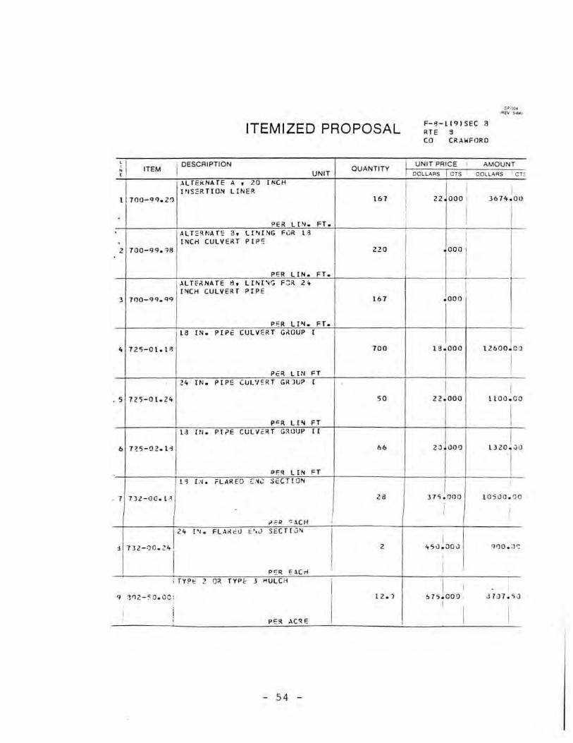
ITEMIZED PROPOSAL F- !l - li9I SEC a FI T E 3 CO (R,!,WFORO
i I ITEM 1 OESCRIPTION QUANTITY
UNIT PAIC E AMOUNT UNIT DOllARS '" DOLL ARS . c r ~
'!'LfEk NAT E , , '0 (~CH
I ,
!fI S:=R TtON LIN ER. I I I 1 00 - 99 . Z!'J 161
I zz aoo l )6H . OU
I . '" l I .~ . FT . , ,
ALT : !HIAE' " ll~{.'~G F v ll. " , . INCH CU LVERT PIP : ! , TOO-99. Qa no
, 0 00 I P'OA LIN . FT .
.\UfrtNATE ., U "; [ 'o'-; F::; il.. " I INCH CULV ER T PIP E 1 1I'lO- 99. QQ 161 . 000
P ER LI .... FT. 18 IN. P IP ': CU LvERT G~OUP I
12.600 10;) , 7 2 'S- Ot . t ll 100 1 8 . 000
I I P':~ L iN FT .- IN • PIP!: CU l'/ !: R T GR)U;:> I I i . , 72S - 0 1. l" 50 lZ~OOO tl 00 . CO
P":R L" FT I ' ld HI. PPE CU l Y': R T G!U)UP " I
6 nS- 02 . li 66 ZJ 000 t lZO~ .)lJ
I>f'q LIN FT I I " I.'l . FLAIl- EO [ .".: :ii:CTf ON I
1 1)l - OO. H " )T 'i . I} O O 1 0500 . ')0 ; , ,
"~II: "' ,!,eM
" '" . F L .\i( eLI t ' , J SECT I ON I ,
1Jl - ·1O·" 1 , 4'i 1l . 00 ') 91) 0 . :1':
p~q E.!..(n I i ry~ !:: ! 0 ' TYPe 1 MULCH
i I , . , 1" 2. - :"O . oc~
I 1 2. .1 ~ 1 :' . 000 J 1iJ l . 'iJ
I i ! I I P ER. :.CqE
- 54 -

ITEMIZED PROPOSAL F-19- 3 1 5 I SEC "-ATE 1 q CO GASCONADE
-r ITEM I DESCRIPTION QUANTITY
UNIT PRic e I AMOUNT 11 UNIT DO~V.I'IS m I OOLL""S l eTS
MOBIL IZATI ON
20 0 00 100 1 618-\ 0 4 '::0 1 20000 0 0 0
I PER l U."II> SU:04 ,
TE IoIP'1IUA,Y ?Av E"'EtH .'04A KK I NG
2 bZZ -1 O .. GO 9. ' 60 00 0 552 . ,) -)
P eR; Jo4IL = ~L T:il.NA TE " 14 1 N. IN SER TI ON LI .'I E.:t
J 7 0C- QQ.14 101 $8 "r°o Z~6J1t _JO
PC;iI: lPl " ~l T':O,'IA 1' ;o " l on:. I WieR. (i"
"[a" LIN!:"
4 7CC- <lQ . ZC '2 Z l OS.'JC
p~ ~ LI N or I .lL TEil'NA T ", 1::' : l ( !H'I'; i- U . l , N.
1000 I CUlV ::"T 1' 1"= , 1 0 ~ - q~ . ?~ 1 . 158
P':'l. LIN FT I I "L TF. II "f.l Te " L PH ~IG "" lit .:' IN . CU LV ER. T PIP!:
b l eO- 'N .QO ., 000
P <: 'l. LI .'II FT
" IN. ?IP ':: CU lV E'l.T Gaou • I -
7 l i:!5- ·H . li h ZlZ 26 . 001) )l11 2 . J:J
I ! ,., LI ~I " I
" [ 'I. C'J;>.·~U-:. .... r : I ; !: T ~L 0' 1 1' _
Is Le) B 1~5 -1 -:: . 1Z " Jo l e . )"
?E~ UN or l " n .. " L,I, :l",v .: ,cc ,
I ,
9 . n1-.:'· ~ .L ·'l 1 " 12 0 000 : 6 l Zr.. . O':
I I I ,
". " .tC-i i I --
- 55 -

ITEMIZED PROPOSAL
~ ITEM I
UNIT QUANTITY
622-10 . 0u 9.b
H'" I Id I .'. "'" n " OU' I
Z 125- 0 1. 18 '" ;>ER UN FT
I lZ l' . . "EHL ' "
1:25-1 0 .1 2 55
", " NFT
I " l" . , "'" s> c w.
I 7) ?-t:O . l a b
Po. "'"
, ro r :'l FO::l "R a J ~c r
-\
I , ,
- 56 -
F-19- 3 15 I SEC a RTE 19 CO GASCONADE
~ I I
,
" ODD
1
, .. ",.
,"flO ~,
,
516 100
'b'O) "
I
I I I I
I , I I I
• , . , I I ,
I I I I

ITEMIZED PROPOSAL F-19- 2f9 I SEC A~ B
ATE 1'1 CO GASCO NA DE
1; ITEM I DESCRIPTION QUANTITY I UNIT PRICE I AMOUNT
UNIT OOll-'''S m I OO U.AA$ m RElOCA TlNG Tc",pmU,lW TRAFFIC I <JassJoo BARRIER
1 6 11-S0.10 1. 314 I
1 '00
I P=R UN FT , ,
TE .,,!p aR ARY P AVE~ t: NT MAR KI NG
bbO 10.::; 2 622-10 . 00 11 60 . 000
P'=1l. ~IL E
AL TeRN'\ Te " " [ .'1 . r"fSERT!ON lINER , 700 - <:19 .14 '"' 23 0110 5 bd 1 CO
Pe R LI' FT ALTcJ: \jATE " z.:. [>1 . ! 'IS:RTt CN LI NER
• 7 (!fJ - 9 Q . z·) 1b " 000 ZS8 4 . 0tJ
I P : :l LIN FT I
At. YERf! AT;: 0> : L INI /IG F:1R I d I N. cut. V E ~ T P [ I>E , 7 00 - 99 . <)~ ';1 000
, PER Ll N FT I
ALT;:;;;;t NAT '= " LINI NG F ') ~ Z't IN. eUlvE;!,T PI?E
• 700-0Q . qq ,. 000
PER li_ FT
" 1 N. P IP E CUL VER r GROUP 1 ! 1 1£5- "1 . 1 8 6(3 Z~ . ,)UO lS 30fl . cr,
I I P~ R LI N FT I
;: " [ 'o. PIP': CU L" ':II. T ';ROUP I
zq lcoo , ,
8 725 - <: 1 . 24 "' I .! -:'h . )('
I I
I ,
PER LP.I FT
Z " tN . C :l .~:Uj ';Ar t:O ~ ': TAL P{"t:
101000 I • 72'i- l : . 1O;: " 16 v . ,) :'}
I I I I P <;R LI N FT I , ,
57

ITEMIZED PROPOSAL F-I Q-2f'HSEC At.8 RTE 19 CO ~ASCONAOE
~ ITEM DESCRIPTION UNIT PRIce AMOUNT
QUANTITY UNIT DOLLARS en DOU .... RS '" 18 IN. flARED END SeCTION
, 73Z-00.18 " "0 000 3360 00
PER EACH
" IN. FLARED ENLl SECTION
2 7J Z- I)O . Z~ Z 1;' 0 00 Z'O CO
?ER EACH SOOD t ~G
J 'Ol- l O. :lO ZOO to 000 lZOO 00
P~ R 50 YO $EC'O PIG
, ~C'i-l J . CC 11 . 7 '00 0 00 Ie 5]0 co
P"R l.C~t:
, SU6T: TAL ~IJA;)W ':' '' 5421,,) 116
• cR I :>o;e .... Il • J- '.i381( AT S TATI ON D2+oid
'iPEC IAl '.tOR" I ;lRI OGE S !
150 0 1 00 T 202-i:' . 5('\ , 15 0 0 OOoJ
PcoR LU~" SUH t l.Sr .... l T 'tC: ""'J Al ( 3 '11O-;"RT ;
, Zr: ?-3~ • .) ~ , l .J ll " . OO()
I 1 :::;0 . ('')
PEA. LU "" SUH I z... .'IS PHJ.L r (<: 1". :'1 '
000 ] I I.'I S PHAlTr r. CC ~C~ c T ~ 1 ~'1-1 0 J '
',40J·" ""1 " · Z·: I TV I':: , "I X I .7 " 0 10. 00
I I I p !: q TON I
. 58 .
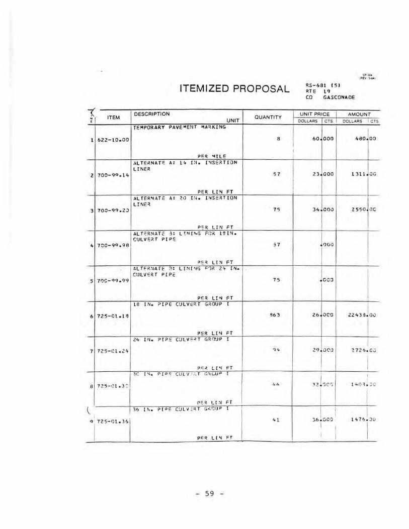
ITEMIZED PR OPOSAL ~S - 68 1 1 5 1 RTE 1 q CO GASCONADE
~. I DESCRIPTION UNIT PAlce AMOUNT ITEM aUANTlTY
UNIT DOtl,O.QS '" OOll,,\.AS I C TS
TEMPOR ARY PAVE wENT ~A::tK ING I l 622 - 10 . 00
, .0 000 480 100 I I
'" "lIL E '\l T e~ N,HJ: " " [,'1 • ['1SEiI. TI.J N
U NH , 700- 9<1. 1 4 " .n . ooo l ) l1 • .1C
'" UN FT ~LT E A~.\Te " " 1:'1. P.Se:.U ( ON L!NE ~
3 100- 9~ . 2J 15 " 00' 1: 55 0 00
P'i'R LI N F T AL r ::R!<IAT C: " L!f.I [~G F~tI. l!
ITEMIZED PROPOSAL RS - 68 1 ( 5 1 RTE 1 q CO GASCONADE
1 ITEM I DESCRIPTION QUANTITY UNIT PRICE I AMOUNT
• UNIT OOll..olilS '" OOllA Ii S l eTS
18 I N. FLARED E ~O SEC TI ON
so.o 1"0 1 13Z-00 . 18 ., 120 000
PER eACH
" [N. FLAR ED END SECTI J III
2 732-00 . 210 , >;, oeo 87. 00
PER ElCH ) 0 ... FLA ~E O E"IO SE C n O N
) 13 Z- 00 .. 3 0 2 2 30 oe o <60 on
PER '! .\CH
" [ .'11. F L,), U') ", ,'40 SEC T I ON
68010c 4 13 Z- CO . J6 2 1 . C.IJCa
' ER ';.l. CH I , SIJ ~ r OT Al ~tJAO"':'Y 4Z:l4 SJ66
I
I , '! II. TOG!: NO. K-~36 ~ " ~ TATIO~
SQ+52 . 75
S? ,=C IA L WO RK 18 11 IDt;rn
7 202-1 0 . 5;:; I A'JOC 4 Cc. ? 8000 . 00
I I PER lU.'1 P su .... I I
" Sl> \ol~l r ~. I:/o\O ""A l r ~R I 9": ES I
110J'JCIJ , lCl -1 C . ) 9 I l uCO . JC
[ ! ;>1'; "- lUi'll' :;U" I
l AS ?HAl _ ~:' ''' PI
loc looo : ,
. ' 4 SPHALTIC C a~CRET= 1 "'.:J- 1? o. ,
q 40 3-1 : . 3 1 1 lC - l D I TYP E , UI ~ I •• 80 . ce
I I I I I
PF. R 7 0 N ' I · 1
- 60 -

ITEMIZED PROPOSAL RS - SHS- I O~8 1 2 t .. t s RT E H Z CO OREGON
, I DESCRIPTION UNIT PRICE AMOUNT , ITEM QUANTIT Y • UNIT • OOlu\~S '" OOLLAflS '" TYPE III OBJEC T MARl( Ell:
150 100 1 6 16 -1 0 ."" 1 0 15 000
I PER E4.CH
, IoIAR'4tNG LI GH T, TY PE 8
, 6 1 6- 1 0 . 'i~ " . 00 OilO 5000 '0
<
'ER S:ACH T E ~P JR ARY TRAFF I C I'AIUI.[fR
1 617-50 • .)0 18 1 " 0110 '+344 00
' ER L" FT ~O:: L ·J C.lfI~l'; TE"IPORAR Y TRAF lC U.il.U E ~ , ~l,,-o;O .l C
,,, 11. 5 0~ 62 .. 4 " ' ER LJ"f FT
"'B fU U. 11k
11 ou~ l co ') 6 111-1 J . Vl 1 IJ }OO . OOO
PE II: LU /IIP ') u~ I T i: "' ;>" fU~Y i'AVE "l eN T _ S ~"G • • ['I • • SO LI D wHIr E IH PEI
6 021-05 .1\ 2 10C ;)00 '00 00
, PER 10 0 FT
PA v" .... e .... T S fR I Pf. R"; '40 V.1. l I AP< .
T 6Zl- 1v . C:'> , 15C . COO )ot) . o')
PER FlO ., I T ;;' I""J ~.lR Y ., ... - ' I ,tr,~
1 ao I ',)-)0 } 07 0 \ 01 ' , " 22 -~ ; . r:C 1 1 • '5 'f P 1: ~ )4t l E ,
, U t ' j. P ( "'c~lV~-l G~mJP
1,J9()O I I
'1'25-Cl ." ' ~ . 3C)8 )8 l l!UZ ':' I
I I 'ER LI_ FT I
- 61 -
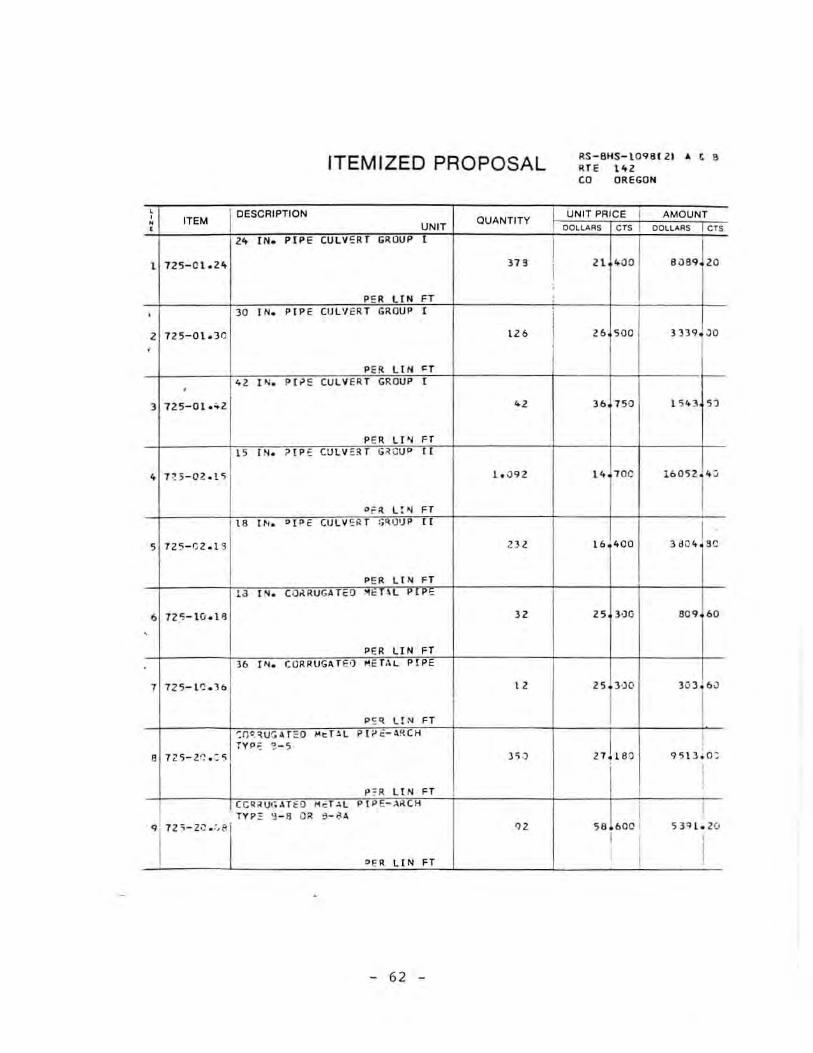
ITEMIZED PROPOSAL
, I DESCRIPTION , ITEM OUANTITY • • UNIT ,. IN. PIP E CULV:R r GRIJUP I
I 125-Cl~H ". P!: R UN FT
, ) 0 [ N. PIPE CULV ERT GROUP I
2 1l5-0 1 ~)" IZ6 ,
PER UN <T
" I'<l . Ph'!: CULVER T GROUP I ,
) 72:'; - 0 1 . .. 2 " PER Lr. FT
IS I .... . 7 IP E CJ lV :=. ;tr G;!CUI> II
41 H - OZ . l ') 1. 0 Ql
Of:!. L :~ F T
" I ~, . "I PE CU lV '::>!. T l;II!)')!>
, 12'5- t;2. 1 S '" PE lt LIN FT
" t ~. C O~RU(,rre!l ~i:T \L PI' .
6 1 2 '5- tv .l ~ JZ
,
'ER LIN FT 36 '". CORRUG:. Te'l !'Ie T;\ L PIPE
1 7Z5- 1 ~ . 3b lZ
pc:q UN FT -:n ':. ~ u :; J,r ~o l'I t:T!.l P t "'~-.1~CH
TVP" '!- s , nS-l0 . ':: S 3 'j ·)
P;R LI N FT
CCI:I.:IUt,.H fD I"I cT.l.l Pt >E-.l.~ (H
TV!> :;: 'J - 9 OR :1 - 0:1 "
'1"'-'0""1 .,
'ER LIN FT
- 62 -
I I , ,
RS-8HS- l OQS I 2 1 0\ t 8 U E H Z CO OREGO N
UN IT PRICE I AMOUNT OOLLARS '" I OOLL.<oA S '"
Z! '00 8USq LO
Z6 '00 )J)q JO
)6 750 1 $ 10 ) "
\4.70C 16052 1"
16 ' 00 3 <10 4 I "
" ]')0 '''ro
" ) ,) 0 ''' ] 6 '
2lLs!) I , Q'513. 0:
I , I I
56 . boe I 53 '11.20 I
I I

ITEM IZED PROPOSAL II.S-8 H5- 109 8 12 1 It. , 6 ATE 10\ 2 CO OREGON
• I DESCAIPTION UNIT PRICE , ITEM QUANTITY
AMOUNT • • I UNIT OO~ I"A RS m oot.L..II "'s I CTS
CORRUGAT ED META L PI P E-ARCH
39/:1 8 100 TYP E 9-1 0 OR 8 - 1JA
1 7l 5-2!l . l O '0 " 600
I P<; R U N "
, , 18 Hh FLAR'EO '" SEe Tro ...
, 13Z-t;C .1 8 108 80 OOU 8640 oc ,
,,, F. i CI-i z; ! N . Fl '\"I ED ;:'NO SEcr ION
) 132-0.:1 . 2<" '6 " 6 000 2 11b 00
P:' II. :: ol,C H
" r.. Fl,\II.E O = ~ o S~CT rOf,
• 132- CC . :\.1 • '51 600 1030]" ,,, 'E lCH
" I ~ . FL'\~ C:D '"0 " " 10,'
70 JOO 5 7 1Z- C'J . 36 , '" DC:)
." fACH
" I "l . Fl AII.EO :l'iO SEc rr ON
6 132 - (,0 . 42 , 7ZC 000 ""1'0 Pt R ':;:ACH
" ~lJ,R!:O '! N:: 'SEC TI ON
3326L" , 7)Z-1r: . 0 'l '6 lO'r" ;>"'11. EACH I.
~I~ FL A"I€,) 10 ... 0 ~;:C ON
5 4 5 1600 l. 16Z1,.o , 1 3Z - ! :1. w' '1 • p~~ :: ACH I ,
-' V' F l AJ>. ~O 'NO Sferr o",
oeo l ! ,
" H Z-I C. t ,} • 728 ZGllZ loc ,
I ,
'" FAC H I I
- 63 -

ITEMIZED PROPOSAL 6-$-T-7117 RTE T CQ ST. CHARLES AND WARREN
i I ITEM I DESCRIPTION
aUANTITY UNIT PRICE I AMOUNT
UNIT OOlLA RS CTS I OOU .... RS CT~
RE/'IO VAL OF I"'PROVE"'E N S
I 1 202-20.10 1 3000 000 30001 00
I PE R LUI''''' SU,", i
CLASS ) E){CAVATI::JN
.2 206-30 . 00 1. 0 46 17 000 171'8 2 00
PER CU YO TYPE 1 OR TTPE Z AGGREGATE FOR
31000 BASE 17 tN. THIC!(' . ) )04-00. n 53' 1 599 00
PER SQ vo ASPHALT CEI'IENT
"jooo t 9 I TU"'tHOUS PAVE~ EN TJ 85-100
" 4 0 t-l O.ll OR AC-l0 .. , , Z)6.S0
> ~ PE R TON >
MINERAL AGGREGAT:
4lZ51oo (BITUMINOUS PAVe~ eH TJ GRADe C
'i 401-20.10 TO " 000
PER TON I PR (:-!F.-LIQU1 O A ~ PH ALT ~c 10 UR
3100) 0; 1 0 1 00 " C " •• 408-1(' .10 170 ,
I >
PER GALL ON ,
CCNSTRUCTI0'i S IGNS
7 f!l!>-ll) . O!, 176 25.000 't 4 00 . 0 0
i >
PER SO FT >
:.oOS ll HAT ( ON I 8 !t 18-1 C. 1'J1l 1 23000 .. 000 -!JOO ') . "J ·'"
I I
P Elt lU!'4P SUM I I j l Z !N . ?(P E (UlV f"R T GrillUP II
nIeoo i "
q 7 .::<; - rZ.ll l 2 ~ l 42~1t . ) O
i ,
, I I !>'!:R l.[N FT I ,
- 64 -
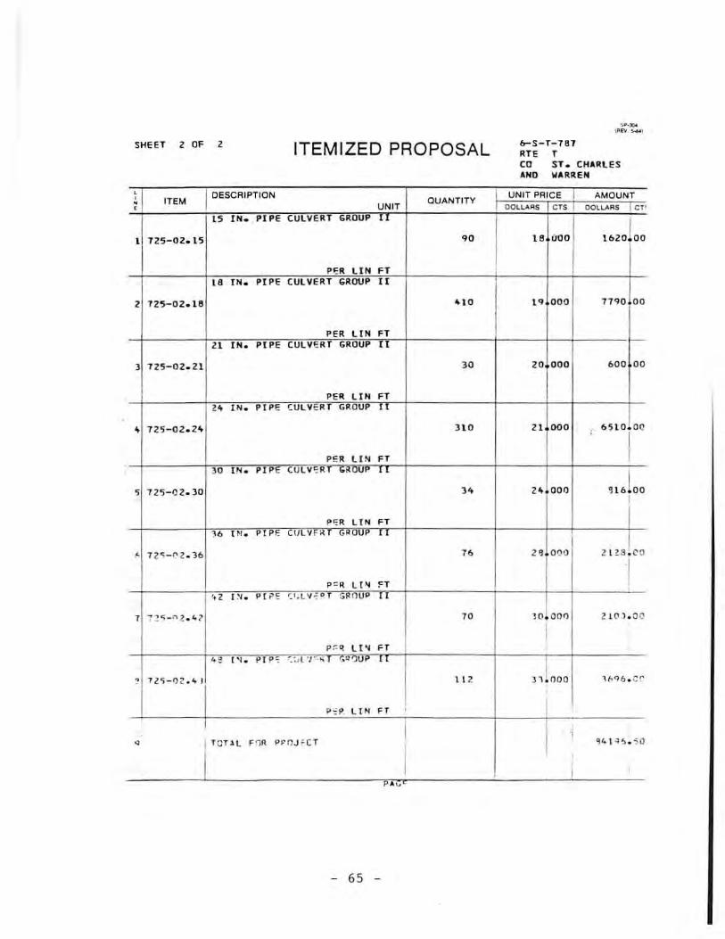
SHEET 2 OF 2 6-S-T-7B 1 ATE T ITEMIZED PROPOSAL CO ST. CHARLES AND WARREN
! I ITEM ! oeSCRIPTlON OUANTITY
UNIT PRIce I AMOUNT . , UNIT OOll .... RS '" I OOUARS j CT'
l5 IN. PIPE CULVE RT GROUP 11
l 725- 02.1 5 .0 16 000 1620 00
P"'R LIN FT L8 I N. PIPE CULVERT GROU P II
2 725- 02 . HI ..0 l' 000 7 7QO 00
PER LIN FT 2l IN. PI PE CULVE AT GROUP II
3 725-0 2. Zl 3 0 20 000 bOO 00
PER LIN FT .- IN • PIPE ( Ul VERT GROUP 11
65 10 L o ... 725-0 2 . 2,,", ]LO Zl 000 , I
P!'OR LI~ FT I 30 IN. PIP E CULV ";R <uu.
2 ..1 000
,
, 72'3 - 02 . )0 ). ~ 1 61oo !
pr:R. LIN FT I ,. I N. P[P F. CtJLV < G'OUP II I " 7 2 ')- ..... 2. )6 Tb " 000 2 123 . C" 0
i P"'1. LIN n I ,
t.2 [ ~I . PI ;>!:' '::' . l'/ ':: " 1" G nup I I
T ":" .~"-"l ." l TO JO . OO f') 2 1(1 l . O;)
I p;:: ~ LIN FT
, , ., 1 ' 1. P I p ~ .. ;, t "I , ," .u, " I , 72') - 1) 2 .4 I H2 n i noa V'Q6 . ;:: ....
p -: ~ LIN FT , , , I I I
" , I Te T l L F '1R p f' nJ ~ C T ~41 .; ~ . S u
I I , I
, , , pI " f.
- 65 -

APPENDIX E
CULVERT SURVEY OF CROSSROAD
REPLACEMENTS OR REHABILITATION
- 66 -
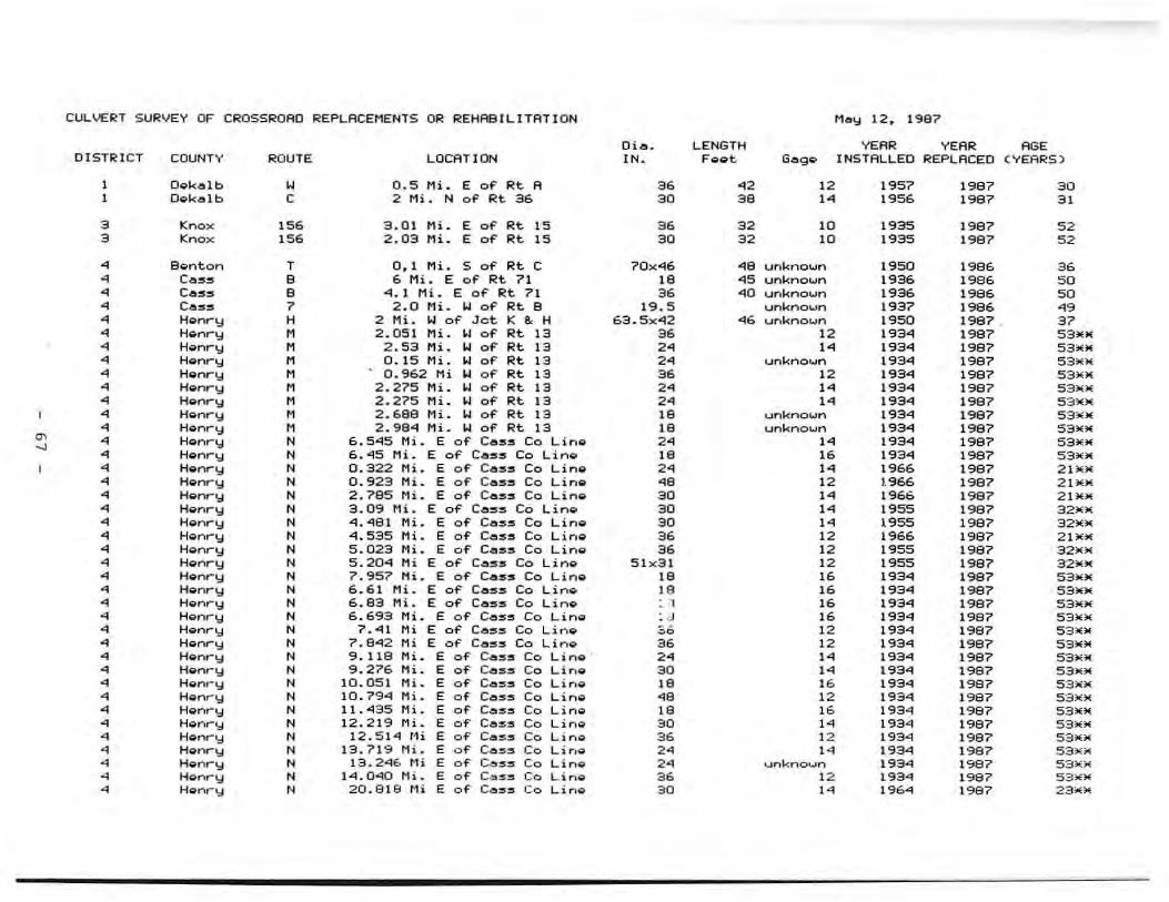
CULVE~T SURVEY OF CROSSROAD REPLACEMENTS OR REHABILITATION Me" 12, 1987
Dia. LENGTH YEAR VEAR AGE OIST~ICT COUNTY ROUTE LOCATION IN . Foe t. Gage INSTALLED REPLACED (YEARS)
1 Oekalb " 0.5 Mi. E of Rt. A 36 .2 12 1957 1987 30 1 Oek.olb C 2 Mi. N of Rt. 36 30 38 ,. 1956 1987 31
3 Knox 156 3.01 Mi. E of Rt. IS 36 32 10 1935 1987 52 3 Knox 156 2.03 Mi. E of Rt. 15 30 32 10 1935 1987 52
• Bon ton T 0.1 Mi. S of Rt C 70x"'l6 "18 unknown 1950 1986 36 • Cess 8 6 Mi. E of Rt 71 18 '"15 unkno .... n 1936 1986 50 • Cess 8 '"1.1 Mi. E of Rt 71 3. "'10 unkno .... n 1936 1986 50 • Ce:5:5 7 2.0 Mi. Io! of Rt. 8 19.5 unkno .... n 1937 1986 •• • Henry H 2 Mi. Io! of Jot K 8.: H 63.5x'"12 "'16 unkno .... n 1950 1987 . 37 • Hgnry M 2 . 051 Mi. a.! of Rt 13 36 12 1934 1987 53MM
• H",nry M 2 .53 Ni. '" of Rt 13 2. 1. 1934 1987 53:':M
• Hgnry M 0 . 15 Mi. j.J of Rt 13 2' unkno .... n 1934 1987 53** • Hgnry M 0 . 962 Mi '" of Rt 13 3. 12 193'"1 1987 53lEM • Hgnry M 2 . 275 Mi . &.! of Rt 13 2. 1. 1934 1987 53lEM • Honry M 2 . 275 Mi. a.! of Rt 13 2. 1. 1934 1987 53MM
• Honry M 2 . 689 Mi. W of Rt 13 18 unkno .... n 1934 1967 53*M
• Henry M 2 . 984 Mi. W of Rt 13 18 unknown 1934 1997 53MM
'" • Henry N 6.5"'15 Mi . E of Ca:5:5 Co Ling 2. ,. 1934 1987 5~j)E*
" • Honry N 6. "l5 Mi. E of C.os:5 Co Lino 18 I. 193 4 1987 53MM
• Ho",-y N 0.322 Mi . E of C.o:5:5 Co Ling 2. ,. 1966 1987 21)1;M
• Honry N 0 . 923 Mi. E of C&:5 :5 Co Ling .8 12 t966 1987 21MM
• Henry N 2.785 Mi. E of C.o:5:5 Co Ling 30 ,. , .. 6 1987 2 1MM
• Hgnry N 3.09 Mi. E of C&:5:5 Co L ing 30 ,. 1955 1987 32MK
• Honry N "l • .q81 Mi. E of C&$$ Co Line 30 H 1955 1987 32MM
• Hgnry N 4.535 Mi. E of C&$$ Co Line 3. 12 1966 1987 21l0(
• Henry N 5.023 Mi. E of C&$:5 Co Lino 3. 12 1955 1987 32l1elle
• Hgnry N 5.204 Mi E of C&:5$ Co Li no 51x31 12 1955 1987 32l1eM
• Henry N 7.957 Mi. E of Cess Co L ino 18 16 193"l 1987 53MM
• Honry N 6.6 1 Mi. E of Cess Co Line 18 16 193.q 1987 53l1eM
• Honry N 6.83 Mi. E of Ces:5 Co Li ne ~ " I. 193"'1 1987 53lf:M
• Hgnry N 6 . 693 Mi. E o f C&$$ Co Ling ; '" I. 193"'1 1987 53)1;M • Honry N 7.41 Mi E of CeS$ Co Lino E.6 12 1934 1997 53lf:M • Henry N 7.8'"12 Ni E of C&S$ Co Ling 36 12 193"'1 1987 53*M • Honry N 9.118Ni. E of Cas$ Co Ling " 2' I. 1934 1997 53*M • Honry N 9.276 Mi. E of Ce$s Co Ling 30 I. 1934 1997 53lf:M • Henry N 10 . 051 Ni. E of Cess Co Line 18 16 1934 1997 5 3 lf:M • Honry N 10.79.q Mi. E of Cess Co Lino .8 12 1934 1997 53)1;101
• Honry N 11 . .q35 Mi. E of CO$$ Co Lino 18 I. 193'" 1987 53lf:M
• Henry N 12.219 Mi. E of CO$$ Co Ling 30 I. 193"l 1987 53:':M
• Henry N 12 .51.q 111 E o f C.o$$ Co Line 3. 12 1934 1987 5 3 lf:M
• Honry N 13.719 Mi . E of Ces$ Co Lir.g 2' I. 193.q 1987 5 3 ** • Hemry N 13.246- Mi E of Ce$$ Co Ling 2 ' unkno .... n 1934 1987 5 3 lf:)E 4 Henry N 1""1.040 Mi. E o f C~$$ Co Line 3. 12 193"l 1987 5 3:':M • Hgnry N 20 . 81B ~1i E of C.o$$ Co Ling .0 I. 196""1 1997 23 :':M

4 Heoonry N 21.135 Hi E o~ C~~~ Co Ling 24 14 1966 1987 2PUE 4 Honry N 21.370 Hi E o~ C~~5 Co Ling 30 14 1966 1987 21j,()( 4 Hgnry N 21.930 Mi. E of C~~5 Co Lin" 3. 12 1966 1987 2 1NM 4 Honry 2 0.25 Mi. E of Jet. :2 & JJ 32)(63 42 12 1956 1987 3 1)(M 4 Honry 2 0.25 Mi. E of Jet 2 So JJ 56 )(38 40 12 1956 1987 3 1 4 H"nr.., 2 0.6 Mi. E Jet :2 60 JJ 32)(63 38 12 1956 1987 3 1M)!; 4 Honr'::j 2 0.6 Mi. E Jet 2 e. JJ 56x 38 "!Q unkno .... n 1956 1997 31 4 HQnry 2 0.55 Mi . E of" Rt. :2 a. NN 20)(38 40 14 1956 1967 31MN 4 Hgnr'=l 2 0. 5 5 Mi. E Jet. Rt 2 8. NN 35.5x23.5 "lQ unknoun 1.56 1'387 31 4 Johnson 0 1.1 Hi. No of Rt. 0 8. EE 30 50 unknown 19"'17 1986 3 . 4 Johnson 88 1.5 Mi. 1.1 o f" Rt 13 2 4 "lQ unknown 1957 1996 29 4 Johnson 00 1.6Ni. E of" Rt M 28x 20 "lQ unknoun 1961 1996 25 4 L~f.oy"tt" 0 1. 3 Mi. N of Rt 1-70 30 "10 unknOloln 1935 1997 52)()( 4 Lcfo<,;4i1O'tte 0 0.9 Mi. S of Jet FF 18 "10 unknown 1935 1986 51 4 Lofoyeootte 0 2.3 Mi. S of Rt 2"'1 24 "10 unknoun 1935 1986 51 4 LofoYfOltt.o a 0.85 Mi. S of Rt 24 24 "10 unkno .... n 1935 1986 51 4 L~f~yfOltt.fOl a 0.1 Mi . N of Rt 1-70 3. 38 12 1935 1987 5 2iMI'( 4 L~f~yroottr;. 0 2.3 Hi 5 of Rt 2"1 24 .q0 unkno ... n 1935 1986 51 4 LaFayo;;.ttr;. a 3.1 Mi. N of Rt 1-70 18 unkno ... n 1935 1997 5 2J11)o1 4 L~Fa""fOlttfOl E Jet Rt E .. FF 54 12 1948 1987 3 9iMM 4 L~fa""o;;.ttr;. F 2.0 Mi. N of Rt. 20 3. 4a unkno ... n 1'36 1986 50 4 Lafa"roottr;. F .q.3 Mi. No of Rt 20 24 58 unkno .... n 1936 1987 5 1 JIll'(
4 Lafayo;;.ttr;. P 0.5 Hi . N of Rt. 24 24 36.5 unkno ... n 1.66 1986 2 0 4 L~Fayo;;.ttr;o U 3.2 Mi. E of Rt. M 24 40 unkno .... n 1960 1987 27MI'(
'" 4 LaFo""o;;.tt.~ U 0.35 Mi. S Jet. U a. M 24 unkno .... n 1960 1987 2 7J11J11 0> 4 L~f'a""o;;.tto 23 1-8Mi. S of Rt PP 24 .q0 unkno ... n 193.q 1986 5 2 4 Lafayroott.o 23 1. 9 Mi . S of Rt. PP 24 .q0 unkno .... n 193.q 1986 5 2 4 L~f'ayroott.o 23 0.5 Mi. S of Rt. PP 30 .q0 unkno .... n 193.q 1986 52 4 L~FayfOltto 131 O.8S Mi. S of Fi!t U 18 .q0 unkno ... n 1931 1986 5 5 4 LoFoyQt.to;;. 131 0.75 Mi. S of" Fi!t. U 18 .q0 unknoun 1931 1986 55 4 LoFoyrootto;;. 131 0.35 Mi. S of" Fi!t. 00 2 4 14 1931 1987 56MM 4 LoFayfOltto FF 1.1 Mi . E of John50n Co Lino 24 "'14 unkno .... n 1949 1987 38MM 4 Po;;.t. t i5 0 1. 9 Mi. E of Rt. 127 2 4 34 14 1934 1987 S a MM 4 PfOlt.ti5 0 1. 7 Mi. E of Rt 127 18 40 1. 1934 1987 5 3 MM 4 PfOlt.ti5 0 1. 5 t1L W of Rt 127 30 45 14 1934 1997 5 3 MJII 4 PfOlt.t.i:5 0 6.4 Mi. E of Fi!t 7 29 x 42 .qQ unkno ... n 1934 199e. 5 2 4 PQt.t.i:5 a 3.6 Mi E of Rt T 3 . 12 1934 1997 5 3 J11M 4 PQt.t.i5 a 2.3 Mi. E of Rt. T 2 4 14 1934 1987 53J11M 4 PQtt.i5 a 2.3 Hi. E of Rt. FF 30 14 1934 1987 53MW 4 PQtt. i :5 a 1. 7 Mi. of Rt FF 2 4 unkno .... n 1934 1987 53MW 4 Potti5 a 4 Mi. E of Rt Ff 3. 12 1934 1987 5 3J11io( 4 Pot.ti5 0 2 Hi. E of Rt Ff 3. 12 1934 1987 53iM": 4 PQt.ti:5 J 8.4 Hi. E of Rt 65 2 4 60 unkno .... n 1932 1996 54 4 PQtt.i15 J 9.3 Mi- E of Rt. 65 18 44 1. 19"" 1986 47 4 PQtt. i 15 J 0 . 2 Hi. E of' Rt. 65 3 0 14 1933 1987 5 .qMiM 4 PfOltti5 J.N At Jet RtQ:5 J a. N 3 . 7 3 14 1932 1986 5 4 4 POt.t.i5 M .3 Hi. E of Rt. V 15 "'16 unkno .... n l'SO 1986 3. 4 Pgt.t.i:5 M 0. :3 Mi. W of Rt V 15 .q6 unkr'o .... n 1940 1986 4 . 4 Pgtt. i15 V J e t Rt U a. V (Wg5t ) 36x2 1 14 19SO 1987 37MloE 4 Pott is V J e t Rt V a. U (EelSt) 15 1. 1950 1987 37M;'; 4 Pgtti:5 V 1. 7 Mi. E of Rt U 3 0 unkr'o .... n 19 50 19B7 37M>':
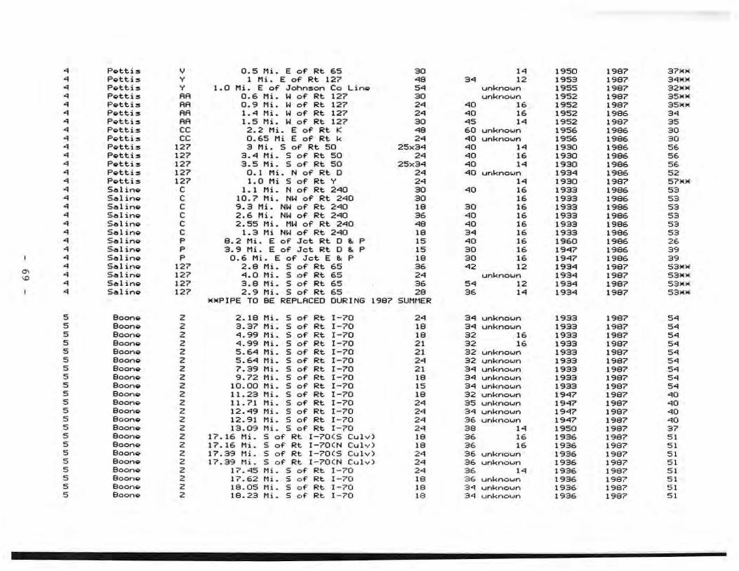
~ PlPtti:s V 0 . 5 Mi. E o~ R:t. 65 30 14 1950 1987 37Jo1M ~ PlPttis Y 1 Mi. E of Rt 127 ~8 3~ 12 1953 1987 34MM ~ PlPtti:s Y 1.0 Mi. E of JOhn:son Co Li n ... 5~ unknown 1955 1987 32Jo1M ~ PlPttis RR 0.6 Mi. W of" Rt 127 30 unkno .... n 1952 1987 35"M • Pvtt i:s RA 0 .9 Mi. W of' Rt 127 2. .0 16 1952 19B7 35M;.o:
• PlPtti:s RR 1.04 Mi. W of Rt 127 2. .0 16 1952 1986 3. • Pvtt.i:s RR 1.5 Mi. W of Rt 127 30 .5 1. 1952 1987 35
• PlPttis ee 2.2 Mi. E of Rt K .8 60 ."mknololn 1956 1986 30 • PlPtti:s ee 0.65 Mi E of Rt k 2. 0<10 unknown 1956 1986 30 • PIPttl:S 127 :3 Mi. S of Rt 50 25x3"'l .0 1. 19:30 1996 56 • P ... t.ti:s 127 3."'l Mi. S of Rt 50 2. ~O 16 1930 1986 56 • PIPtti:s 127 3. 5 Mi. S of Rt. 50 25x34 .0 1. 1930 1986 56 • ?vtti:s 127 o. 1 Mi. N of Rt. 0 2. 40 unknol.Jn 193"'1 1986 52 ~ PlPtti:s 127 1.0 Mi 5 of' Rt Y 2~ 1. 1930 1987 57)001
• S,e,l ing e 1. 1 Mi. N of' Rt 2"'lQ 30 .0 16 1933 1986 53
• 5.e111 in ... e 10.7 Hi. NW of' Rt 240 30 16 1933 198& 53 • $&1 inso e 9 . :3 Hi. NW of' Rt 2"fQ 18 30 16 1933 1986 53
• Seling, e 2.6 tti. NW of' Rt. 2"lQ 36 .0 16 1933 1986 53
• Sal in ... e 2.55 tti. M~" of Rt 2"'10 .8 .0 16 1933 1986 53
• Sel i nv e 1.3 Hi NW of' Rt 2"'10 18 3. 16 1933 1986 53
• S .e!l1 ino;. P B. 2 Mi. E of Jet Rt C ~ P 15 .0 16 1960 1986 26 • S.e!llino;. P 3.9 Mi. E of Jet Rt C ~ P 15 30 16 1947 1986 39 • 5.e!11 ino;. P 0 . 6 Mi. E of Jet E e. p 18 30 16 1947 1986 39
• Selino;. 127 2 . B Mi. S of Rt 65 36 .2 12 1934 1987 S3MM
'" • S.e!ll ino;. 127 '"'1.0 Mi. S of Rt 65 2. unkno ..... n 1934 19B7 53_)0;
'" • S.e!lIino;. 127 3.B Mi. S of Rt 65 36 5. 12 1934 19B7 53_)0;
• Sel ino;. 127 2.9 Mi. S of Rt 65 28 36 1. 1934 19B7 53_)0;" )ii_PIPE TO BE REPLACED CURING 19B7 SUMMER
5 Boono;. 2 2.1B Mi. S of Rt 1-70 2. 3'"'1 unkno ..... n 1933 1987 5. 5 Boono;. 2 3.37 Mi . S of Rt 1-70 18 3"1 unkno ..... n 1933 19B7 5. 5 Boono;. 2 4.99 Mi . S of Rt 1-70 18 32 16 1933 19B7 5. 5 Boono;. 2 4 . 99 Mi. S of Rt 1- 70 21 32 16 1933 1997 5. 5 Boono;. 2 5.64 Mi. S of Rt 1-70 2 1 32 .... nkno ..... n 1933 1997 5. 5 Boono;. 2 5.64 Mi. S of Rt 1-70 2~ 32 unkno ..... n 1933 19B7 5. 5 BoonQ 2 7.39 Mi . S of Rt 1-70 21 3'"'1 unkno ..... n 1933 1997 5. 5 Boono;. 2 9 . 72 Mi. S of Rt 1-70 18 34 ur-.kno ..... n 1933 19B7 5. 5 Boono;. 2 10 .00 Mi. S of Rt 1-70 15 3 4 unkno ..... n 1933 19B7 5. 5 Boon.;. 2 11.23 Mi. S of Rt 1-70 18 32 unkno ..... n 1947 1987 .0 5 BoonQ 2 11. 71 Mi. S of' Rt 1-70 2. 35 unkno ..... n 1947 19B7 '0 5 BoonQ 2 12 . '"'19 Mi. S of' Rt 1-70 2. 3"1 unkno ..... n 1947 1987 .0 5 800no;. 2 12.91 Mi. S of' Rt 1-70 2. 36 unkno ..... n 1947 1987 ~O 5 800no;. 2 13.09 Mi. S of' Rt 1-70 2~ 38 .. 1950 1987 37 5 Boono 2 17.16 Mi. S of' Rt I-70 (S CuI ,,) 18 36 16 1936 1987 51 5 Boono 2 17.16 Mi. S of' Rt I -70( N CuIv) 18 3. 16 1936 1997 51 5 Boono;. 2 17 .39 t1i. S of' Rt 1-70(S Cu I v) 2. 36 unknown 1936 19B7 5 1 5 800no;. 2 17.39 Mi. S of' Rt I-70 ( N CuIv) 2. 36 unkno ..... n 1936 1997 51 5 80000;. 2 17 . 45 Mi. S of' Rt 1-70 24 36 14 1936 19B7 51 5 Boono;. 2 17.62 Mi. S o f' Rt 1-70 18 36 .... nkno ..... n 1936 1997 51 5 BoonQ 2 18.05 Mi. S o f' Rt 1-70 18 3 4 .... nknown 1936 1987 5 1 5 Boon.;. 2 19.23 Mi. S of' Rt. I - r"O 18 34 .... nknown 1936 1987 51
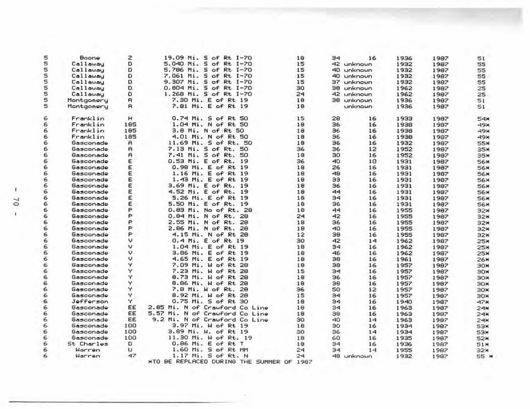
5 Boon~ 2 19.09 Mi. S of" fO!t 1-70 1. 3. 1. 1936 1997 51 5 Callo .... ay 0 5.0"'0 Mi. S of" Rt 1-7 0 15 "12 unknoun 1932 1987 55 5 Coll.ellwo!IY 0 5.786 Mi. 5 of Rt. 1-7 0 15 "'1O unknown 1932 1987 5 5 5 Collouoy 0 7.061 Mi. S of Rt. 1-70 15 "'10 unknoun 1932 1997 55 5 C.elll.e.woy 0 9 . 307 Mi. S of Rt. 1-70 15 3 7 .... nknoun 19:32 1997 5 5 5 Calloway O. 0 . 804 Mi. S of Rt. 1-70 30 3 8 unkl"lOun }962 1987 2 5 5 Callo .... ay 0 1.269 Mi. S of Rt. 1-70 2. -'12 unknown 1962 1':187 2 5 5 Montgorn~,..y A 7.30 Mi . E of Rt 19 1. 38 unknown 1936 1987 51 5 Mo ntgo mg,-y A 7.81 Mi. E of' Rt. 19 1. unk n o un 1936 1987 51
• Fronlod in H 0 . 74 Mi. S of' Rt 50 15 2. ,. 1933 1997 54~
6 Franklin 185 1.0.q Mi. N of' Rt 50 1. 36 16 1938 1997 .9' 6 Frankl in 185 3.8 Mi. N of · Rt 50 1. 36 16 1938 1987 ... 6 Frer"lklin 185 "1 . 01 Mi. N of Rt 50 1. 36 16 1938 1987 .9' 6 GO lllconod,", A 11. 69 Mi. S of Rt. 50 1. 36 16 1932 1987 55' 6 Go:sconodo A 7.13 Mi. S of Rt . 50 36 36 12 1952 1':187 35' 6 Geolllconedo A 7.·<U Mi. S of RI:.. 50 1. 30 1. 1952 1987 35' 6 GO:5conedo E 0 . 53 Mi. E of" Rt. . 19 3. .0 10 1931 1987 5.' 6 6o:5co nedo E 0 . 98 Mi. E of" Rt. 19 1. 26 16 1931 1987 5.' 6 6eo:5coneodo E 1 . 16 Mi. E of" Rt. 19 1. •• 16 1931 1987 5 6 ' 6 6eo~conedo E 1."13 Mi. E of" Rt. 19 1. 33 16 1931 1987 5 6. 6 Geo:5conodo E 3 . 69 Mi. E of" Rt. . 19 1. 36 16 1931 1987 5 • • 6 6o:sconedo E "1.52 Mi. E of" Rt. . 19 1. .. 16 1931 1987 5 6 '
~ 6 6o:5conodo E 5.26 Mi. E of'" Rt. 19 1. 3. 16 1931 1987 56. 0 • GO:5conedo E 5 . 50 Mi. E of" Rt. . 19 1. 3 6 1. 1931 1987 5 • •
6 Geo:5conedo P 0.83 Mi. No of Rt.. 28 1. .. 16 1955 1987 32' 6 GO:5conedo P 0.9"1 Mi. N of" Rt. . 2. 2. . 2 16 1955 1987 32. 6 6o:5conedo P 2 . 55 Mi. N of Rt. . 2. 1. 36 16 1955 1987 3 Z-6 6o:5conedo P 2.86 Mi. N of Rt. . 2. 1. .0 16 1955 1987 32' 6 6o:sconodo P 4.15Mi. N of Rt. 28 12 3. 16 1955 19B7 32' • 6o:sconodo V 0 . "1 Mi. E of" Rt. 19 30 .2 1. 1962 1987 2"* • 6o:sc onodo V 1.0"1 Hi. E of Rt. 19 ,. 3. ,. 1962 1987 25' • 6 o:sconodo V 3.86 Hi. E of Rt 19 1. •• 1. 1962 1987 25' 6 6o:sconodo V "'.65 Hi. E of Rt. 19 1. 3. 16 1961 198? 26' 6 Ge:soonod ... Y 7.09 Mi. W of Rt. 2B 1. 3. 1. 195? 198? 30' b 6o:5conodo Y 7 . 23 Hi. W o f Rt. 28 15 3. 16 19 57 1987 30' 6 GO:5c onodo Y 8.73 Mi. W of" Rt. 28 1. 36 1. 1957 1987 30' • 6o:5conodo Y 8.86 Mi. W of" Rt. 28 1. 3 . 16 1957 19B? 30' 6 GO:5conodo Y 7.B Ml. W of Rt.. 2. 36 50 12 1957 1987 30. 6 6o:5conodo Y 9.92 Mi. W of Rt 28 15 3 . 16 1957 19B? 30' 6 J ... f"Fo l"":5on Y 0.75 Mi. S of Rt 30 1. 3 . 16 19"10 198? .7' 6 GO:5co nodo EE 2 . 85 Mi. N of Cl""o ... fol""d Co Lino ,. 3 . 16 1963 198? 2.' 6 6o:5conodo EE 5.57 Ml. N of Cro ... ford Co Lino ,. 3. ,. 1963 19B? 2.' • 6o:5conod ... EE 9.2 Mi. N of Cro ... ford Co Lino 30 .0 ,. 1963 1987 2.' • 6o:sc onodo 100 3.97 Mi. W of Rt. 19 1. 3 0 1. 19 3"1 1997 53> 6 6o:sco nodo 100 3 . B9 Ml. H. of Rt 19 30 36 ,. 1934 1987 53. 6 GO:5conodo 10 0 11.30 Mi. W o f Rt. 19 1. 60 16 1935 198? 5 2. 6 s t. Chol""l o :s 0 0.86 Mi. E of Rt. T 1. 3 . 16 193 6 1987 51' • Worrl;ln U 1.60 ~1i. 5 01' Rt. 11M 2 . 3 . 1. 19 S5 1987 3 2)( 6 Worron .7 1.1 7 t1i. 5 0 1' Rt . f< 2 . "18 unknoun 1932 1987 5 5 •
_ro 8E REPLACED DURING THE S UMMER OF 198 7

NOTE: Th9 following li~t i~ pipe replaced in Oi~trict 6 ~der Contr~ct in 1986 ProjQct 6-s-T-787. Data tekQn from 28 ~hQ8t5.
• st Ch~rle~ T Ste . 110+76 .0 3"" Unknown 1935 1986 5 1 • st Ch~rlv5 T Ste . 1 17+6"1 18 3~ Unk ..... own 1935 1986 51 • st Charles T st~ . 165+1'9 2. 68 Unk ..... own 1935 1'986 51 • st Charles T ste. 165+78 2. 76 Unknown 1935 1'96e. 5 1
• st Char-Ies T Ste. 226+97 2. 34 Unkno .... n 1935 1'96e. 51
• st Cher-Ies T st.ell. 251+68 2. "10 Unknown 1 '935 1'986 51
• st Ch.or-IQS T St.ell. 262+30 18 "10 Unknown 1935 1'966 5 1 • st Cht!r- Ie ~ T St.ell. 270+3 1 .8 36 Unkno .... n 1935 1'966 51 • st Cht!r-Ie~ T St.ell. 332+50 18 34 Ur,kno .... n 1 '935 1'986 51
• st Cher-le~ T St.ell. 34"1+47 18 46 Unkno .... n 1935 1'986 51 • St Charles T Ste. 390+59 2. 34 Unknown 1935 1986 51 • St Cherles T Sta. 438+53 18 34 Unknown 1'935 1'986 51 • St Ch",r-Ies T Ste. 4"11+18 •• "12 Unknown 1'935 1'986 51 • St Ch~rle~ T Sta. 51"1 +00 18 32 Unknown 1935 1986 51 • St Ch.ellr-Ie5 T Ste. 5"10+88 12 30 Unknown 1 '949 1986 .7 • St Ch~r-I G:5 T Ste. 556+70 2. 34 Unknown 19"" 1986 '7 • St Charles T ste.572+6 3 2 1 30 Unkno .... n 1 ."" 1986 .7 • St Charlos T ste . 602 +66 12 28 Unkno .... n 1949 1986 .7 • St Charles T ste. 620+33 12 28 Unknown 19"" 1986 .7 • St Charl es T ste . 632+70 15 30 Unknown 1949 1986 .7 ..., • St Charles T st~ . 639+06 18 32 Unkno .... n 19"" 1986 37 ~ • St Ch~rIG:5 T sta. 650+82 18 30 Unknown I''''' 1986 .7 • St Charles T Sta . 661+14 . 8 12 30 Unkno .... n 19"" 1986 .7 • St CharlG:5 T ste. 670+82.5 12 36 Unknown 1949 1986 .7 • St Ch~rlo:5 T ste . 687+00 12 34 Unknown 19"" 1986 37 • St Ch~r-Ie:5 T stt!. 741+54.5 •• 34 Unkno .... n 19"" 1986 .7 • St Ch~r-IQ:5 T st.ell. 749+53.8 .2 38 Unkno .... n 1949 1986 .7 • St Ch~r-Ie:5 T Ste. 756+19 .8 76 Unknown 1949 1986 '7 • St Ch~r-Ie:5 T st.e. 761+80 .2 32 Unknown 1949 1986 '7 • St Char-Ie :5 T St.e. 793+95 18 30 Unkno .... n 19"" 1986 .7 • St. Ch~r-Ie:5 T St.ell. 807+57.9 12 30 Unkno .... n 19"" 1986 .7 • St. Ch~r-le:5 T st.~. 895+00 18 30 Unknown 19"" 1986 .7 • St Charle:5 T Ste. 852+S7 2. 24 Unkno .... n 19"" 1986 '7 • St Charle5 T Ste . 865+65 18 30 Unkno .... n
1 ."" 1986 .7
• st Charie5 T Ste . 882+22 15 30 Unkno .... n 19"" 1986 .7
• St Cht!r- IQ:5 T sta . 886+6"1 15 30 Unkno .... n 1 ."" 1986 37
• St CherlQ:5 T sta . 9"15+00 12 36 Unkno .... n 19"" 1986 .7 • St Ch~rle5 T sta. 979+00 18 38 Unknown 1949 1986 .7
NOTE: ThQ follo .... ing li s t is pipe roplocGd under contr-oc t in 1987, ProjQct F- 19-3(S) Stile 8
• G~:5conodtil I' sta . 538+"lO 18 40 Unknown 1930 1987 57
• Gosconodtil I' sta. 538+75 18 .1 Unknown 1930 1987 57
• 6osconadtil I. sta . 5"17+50 18 "14 Unknown 1930 1987 57
NOTE: ThQ follo .... ing Ii st i:5 pipe rGpl~cGd or relinod und Qr contrac t in 1987 , Project Rs-681 ( S)
• G ... s conadtil I' st.el. 12+00 18 .1 I. 1'36 1'987 51

6 Ge:=;coned~ 19 St.e. 27+98 18 46 16 1936 1987 51 6 Gesconedg 19 St..eI. 38+00 18 45 16 1936 1987 51 6 Gosconodg 19 St..e.. 87+65 18 52 16 1936 1987 51 6 6e:sconed ... 19 St..e. 9<;1+00 18 48 16 1936 1987 51 6 GO:5coned ... 19 St-e. 101+85 24 75 16 1936 1987 51 6 G8:5conedg 19 See . 108+00 18 46 16 1936 1987 5 1 6 Ge15conod ... 19 St.e. 1"18+39 18 42 16 1936 1987 51 6 Gesconodg 19 St.e. 157+00 18 39 16 1936 1987 5 1 6 Ge:sconodQ 19 St-e. 167+66 18 41 16 1936 1987 51 6 Ge:5conod ... 19 See. 172+00 18 41 16 1'336 1987 51 6 Gesconedo 19 St.e. 179+00 18 42 16 1936 1987 5 1 6 Ge:5ocned ... 19 St.e. 189+00 18 50 16 1936 1987 5 1 6 Ge:5ccnedQ 19 St.e. 199+36 18 41 16 1936 1987 51 6 Gesconodg 19 St.e. 208+35 18 52 16 1936 1997 51 6 Ge:5conedg 19 St.e. 228+00 18 41 16 1936 1997 5 1 6 GesccnedQ 19 St. .eII. 232+85 24 57 14 19:36 1987 51 6 Gesconedg 19 St..eI. 2 43+13 18 41 16 1936 1987 5 1 6 Go:sconedQ 19 St..eII. 269+70 18 40 16 1936 1987 51 6 Gesconedg 19 St.e. 296+35 30 44 14 1936 1997 51 6 Gasconedg 19 St..eII. 308+19 24 44 14 1937 1987 50 6 Gescon&dg 19 St-e . 318+45 18 41 16 1937 1997 50 6 Gesconodg 19 St.e. 329+55 24 50 14 1937 1987 50 6 Ga:sconado 19 Sta. 335+10 18 35 16 1937 1997 50
" 6 Ge.:scone.do 19 5ta. 338+"13 18 39 Unkno .... n 1937 1987 50
~ 6 Ge.:sconado 19 St-a . 379+20 36 41 12 1937 1997 50
NOTE: Tho following li:st is pipo roplacod o r rolinod undor contract in 1987 , Projoct F-19-2(9) , Soc A eo 8
6 Ge.:sconado 19 St.a . 108+67 18 46 Unkno .... n 1932 1987 55 6 Ga:sconado 19 Sta . 113+61 18 4 5 Unknown 1932 1997 55 6 Ga:sconado 19 St.a. 139+72 18 60 Unkno .... n 1932 1987 55 6 Ga:sconado 19 Sta. 144+55 18 "12 Unknown 1'332 1987 55 6 Ge.:sconado 19 Sta. 153+98 18 57 Unkno ... n 1932 1987 55 6 Ge.:sconado 19 Sta. 187+68 18 "17 Unkno ... n 1'332 1987 55 6 Ge.:sconado 19 Sta . 203+00 18 "18 Unknown 19:32 1987 55 6 Ge.:sconado 19 Sta . 210+00 18 "14 Unknown 1932 1987 55 6 Ga:sconade;. 19 Sta . 227+50 18 "14 Unknown 1932 1987 55 6 Ga:sconado 19 Sta . 30"1+56 18 41 Unkno ... n 1932 1987 55 6 Ga:sconado 19 Sta. 353+30 18 50 Unkno .... n 1932 1987 55 6 Ga:sconado 19 Sta. 367+54 18 57 Unkno ... n 1932 1987 55 6 Ga:sconado 19 Sta . 372+70 18 53 Unkno .... n 1932 1997 55 6 Ga:sconado 19 Sta. 386+00 18 "17 Unkno .... n 1932 1987 55 6 Gasconado 19 St-a. 412+68 18 "17 Unkno .... n 19:32 1987 55 6 Ga:sconado 19 Sta. 425+00 24 "14 Unknoun 1932 1997 55 6 Ga:sconado 19 St.eo. 428+'"'17 18 50 Unknown 1932 1987 55 6 Ga:sconado 19 Sta. 503+6"1 18 77 Unknown 1932 1987 55 6 Gazoconadg 19 Sta . 510+25 24 76 Unkno .... n 1932 1987 55
NOTE: Tho Following li:st is pipo roplacod or r~linod ur",dgr cont.-<iilct in 1987, P.-oje;.ct F - l'3-3 ( 5), SgC A
6 Ga$con<iildg 19 Sta. 7 5+00 I" 50 16 1931 1987 56

6 G.!I:5conoeld~ ,. Sto. '31+50 IS 55 16 1931 1987 56 6 Gesconoeldg, ,. Sto. 105+80 ,. 6S Unknown 1'331 1987 56 6 Gasoonoeld,., " Sto. 112+30 ,. 51 Unknoun 1931 1967 56 6 Ge:5con.e.do ,. Sto. 127+30 ,. 52 Unknoun 1931 1987 56 6 G.eII::5oonl!ldo " Stb. 136+25 ,. 68 Unkno .... n 1931 1'387 56 6 Go'!I:5co nad.., " Sta. 139+75 ,. 51 Unkno .... n 1931 19 87 56 6 Go'!I:5con.eld ... ,. St.a. 147+20 ,. 76 Unknown 1931 19B? 56 6 GO::5oonod ... ,. Sto. 14<;1+50 15 55 16 1931 1987 56 6 G&:5oono'!ldQ ,. Ste. 157+15 ,. 46 Unknown 1931 1987 56 6 Gesoonoeldg ,. Sta. 169+60 ,. 60 Unknown 1931 1987 56 6 Gasoono'!ldg ,. St.el. 177+50 ,. 52 Unknown 1931 1987 56 6 Ga:5conGdg
" S -::' oeI. 180+05 ,. 45 Unknown 1931 1987 56 6 Ge:scono'!ldo ,. Ste . 185+00 ,. 68 Unkno ....... 1931 1987 56 6 GG::5conoeldg
" Sta. 196+75 ,. 48 Unknown 1931 1987 56
6 GoeI:5conado " Stoel. 199+90 ,. 71 Unkno .... n 1931 1987 56 6 GO:5conodo ,. Stoel. 207+50 18 43 Unknoun 1930 1987 57 6 GO:5coned.., ,. Ste. 216+67 ,. 58 Unkno .... n "30 1987 57 6 GO:5conoelldq " St.a. 224+00 ,. 44 Unknoun ,.30 1987 57 6 GoeII~conoelldq " St.a. 226+50 ,. 50 Unkno un 1930 1987 57 6 GoeII~conad" " Sta . 234+50 ,. 45 Unknoun 1930 1987 57 6 GoeII~conad" " St..e.. 238+50 ,. 54 Unknoun 1930 1987 57 6 G.e.scon.e.d~ " St.o. 245+60 2. 51 Unknoun 1930 1987 57 6 G.e.~con.e.d" " St..e.. 252+23 12 50 Unknoun ,.30 1987 57 6 G.e.~c:on.e.d" " St.e.. 262+96 15 45 Unknoun 1930 1987 57
" 6 GG~con.e.d" 19 St.a. 2 6 5+10 ,. 54 Unknoun 1930 1987 57 w 6 Ga~con.e.dg " Sta. 275+60 2. 62 Unknoun 1930 1987 57 6 Ga~con.e.dg " St.a. 282+90 ,. "'19 Unknoun "30 1987 57 6 G.e.~con.e.dq " St..e.. 289+50 ,. 85 Unknoun ,.30 1987 57 6 Ga~con.e.dg " St..e. . 297+63 15 61 Unknoun 1930 1987 57 6 Gasconadq " St.oeII. 300+30 ,. 48 Unknoun ,.30 1987 57 6 Gasconad" " St..s. 303+50 ,. 43 Unknoun ,.30 1987 57 6 Gascon4d~ 19 St.a. 309+20 ,. 58 Unknoun ,.30 1987 57 6 Gosconad" " St..e.. 321+85 ,. 67 Unkno un ,.30 1987 57 6 Gbsconadg 19 St.s. 334+55 ,. 49 Unknoun ,.30 1987 57 6 64SCOnodg " St.o. 338+20 ,. 63 Unknoun 1930 1987 5 7 6 Gasconadg " St.o. 340+25 ,. 61 Unknoun ,.30 1987 57 6 Ga:sconadg 19 St.o. 355+10 ,. 52 Unknoun 1930 1987 57 6 Go~conod..- " St.o. 364+45 ,. 64 Unknoun 1930 1987 57 6 GasconodQ ,. 5to. 374+65 ,. 43 Unknoun 1930 1987 57 6 G.s~c:on.sdQ 19 5t.:t. 392+20 ,. 53 Unkno .... n 1930 1987 57 6 GasconodQ
" 5t..e.. 406+90 18 55 Unknoun ,.30 1987 57 6 6osconadQ 19 St.a. 430+7 0 ,. 65 Unkno .... n 1930 1987 57 6 G05COndodQ " St.e. "'164+00 ,. "'1"'1 Unknoun 1930 1987 57 6 6.e.5con.:td..- "
St.eo. "'178+20 ,. 52 Unknown 1930 1987 57 6 G65coneod", " Sto. 479+60 ,. 54 Unknown 1930 1987 57 6 Ga5con.e.d..- 19 St.e.. 494+75 ,. "'IS Unknown 1930 1987 57 6 GeosconeodQ " 5te. 502+70 ,. 52 Unknown 1930 1987 57
• Leoclw.dQ J 1. 6 Mi I~ of' Jct 5 e. J 2 4 "'10 unknown 1948 1987 S9 e L.e.c:lw.d~ J 2.7 Mi. L·j gf' Jct 5 e. J 2 . 40 u nknown 1948 1987 3.

8 L.e.clgdo J 2.9 Mi . W of' Jet. 5 e. J 18 36 unkn own 19"'19 1987 3. 8 LeclodQ J 1."1 Mi. I-! of' Jet 5 & J 30 "10 unknown 1948 1987 3. 8 PhGlp:5 72 "l.3 Mi. S of' Jet 72 e. p 18 2 "'1 unkno .... n 193"1 1997 53 8 Stong 13 .2 Mi. S of Jet 13 e. 248 15 :30 unknown 193"" 1987 53
No t ... : Tho fo ll ow ing li:5t is pip ... roplecod undor contract in Oist. • (Job No. 9 -5-68-270) Doto tekon from 2 8 :shggt:s
• Ognt 68 Ste. 3+18 18 "'16 u n known 1933 1986- 53 9 Dont 68 St.a . 15+95 2 . 56 unknown 1933 198& 53 9 Dont. 6 8 Sto . 39+35 2 . 56 unknown 1933 1986 53 9 Dont. 68 St.a. "!5+1S 18 "'10 unknoun 1933 1986 53 • Dont. . 8 St.a. 046+30 18 "'10 unkno .... n 1933 1986 53 9 Dont. 68 St eo . 52+60 18 36 unknown 1933 1986 53 9 Dont 6 8 Sta. 59+9"'1 2. 38 unknown 1933 1996 53 9 Dont 68 Sta. 71+34 18 32 u nknown 1933 1986 53 9 Qgnt . 8 Ste. 99+40 18 38 unknown 1933 1986 53 9 Cont. . 8 Sta . 93+70 18 39 unknOl..ln 1933 1986 53 9 Don t 68 St-ll. 1 15+00 18 36 unknown 1933 1996 53 9 Dont •• Sta. 136+00 18 36 u nknown 1932 1986 "" 9 Dont 6 8 St~ . 148+75 18 32 unkno .... n 1'332 1986 "" 9 Dont .8 St~ . 190+22 2. 34 ~nkno .... n 1932 19 8 6 5. 9 Dont 68 St~. 197+31 18 82 '-nkno .... n 1932 1996 5. 9 Dont 68 St~ . 200+30 18 .q6 unknown 1932 1996 "" 9 Do nt 68 St~ . 2 10+95 18 32 unknown 1932 1986 "" " 9 Do;nt .8 St~. 213+12 2. .q0 unkno .... n 1932 1986 5. A • Dont .8 St~. 215+95 2. 36 unknown 1932 1986 5 . 9 Dont .8 St~. 234+90 18 34 .... nknown 1932 1986 "" 9 Dont .8 St~. 244+50 2. .q0 unkno...n 1932 1986 5 . 9 Oont .8 St~. 2 4 6 +50 2. 32 unkno .... n 1932 1996 "" 9 Dont 69 St~. 250+25 18 40 unkno .... n 193.q 1986 52 9 Do n t 68 St~. 269+45 18 32 unknown 193.q 1'396 52 9 Do n t 68 St~. 27 1+40 18 38 unkno .... n 193.q 1996 52 9 Dont 68 St~. 285+00 30 4 0 unkno .... n 1934 1986 52 • Oont 68 St~ . 29 1+35 30 32 unkno .... n 1934 1986 52 9 Dont 68 St~. 302+95 2. 4 0 unkno .... n 193 4 19" 52 • Oont .8 Ste. 305+60 18 38 unkno .... n 1934 1986 52 • Do;nt .8 Ste . 307+40 18 44 u nkn o .... n 1934 1'386 52 9 Oont 68 St~. 3 13+00 18 42 u,-,kno .... n 1934 1986 52 9 Dont 68 Ste . 331+50 2 . 32 unknoun 193< 1996 52 9 Dont 68 Ste. 335+95 18 3 4 unknoun 1934 1986 52 9 Oo;nt 68 Ste . 3"11+58 2. 3 4 unkno .... n 1934 1996 52 9 Oo,-,t •• Ste . 3 4 5 +0 0 2. .q0 unknoun 1934 1986 52 9 Dont 68 Ste. 359+62 30 33 unknown 1934 1986 52 9 Dont 68 Ste. 386+25 18 39 unknoun 1934 1996 52 • Do;nt .8 St./!. 389+ 15 18 38 unkno .... n 193 4 1986 52 9 Dont 68 St../!. 397+30 18 36 unkno .... n 1934 1986 5 2 9 Dont 68 St..!!>. 412+50 30 .q6 unknown 1934 1986 5 2 9 Dont .8 St. .!!> . .q22+9S 18 32 unknown 1934 1986 52 9 Dont .8 St..eI . 447+70 18 32 unkno wn 1934 1986. 52 9 Dont 68 St..eI. 450+06 18 34 u.-.known 1934 1'386 52 9 Oo;nt .8 St..!!>. 4 68+28 2" 32 unknown 1934 1986 52

9 Ognt. 68 Ste. "175+86 18 32 unkno .... n 193"1 1986 52 9 Dont 68 Ste. 476+92 18 :32 unkno .... n 1934 1986 52 9 Dont 68 Ste. 481+80 18 :32 ... mknown 1934 1986 52
NOTE: T~ foll0 .... in9 li5t of' in~tellation5 woro plecod undor contract in 1995 (Job No. 9-5-95-25"". Soc A Oate takon from 28 5hoot~.
9 Wright 95 Ste. 112+90 18 4"1 unkno .... n 1933 1985 52 9 \.olright. 95 Ste. 116.+60 18 38 unknown 1933 1985 52 9 Wright. 95 Sto. 121+25 18 40 unknown 1933 1985 52 9 L-Jright 95 Ste. 17"'1+"10 18 42 unknown 1933 1985 52 9 Wright. 95 St/!!!. 179+50 2. "'12 unknown 1933 1985 52 • Wright. 95 St,(!l. 236+00 18 72 unkno .... n 1933 1985 52 9 W,-ight 95 Ste. 2"'11+45 18 39 unknoun 1933 1985 52 9 wright 95 Ste. 260+00 18 "'18 unknown 1933 1985 52 9 l"right 95 Sto. 298+75 18 40 unknoun 1933 1985 52 9 Wright 95 Sto. 305+60 18 "'Ie. unkno .. ,on 1933 1985 52 9 W..-ight 95 Ste. 309+80 2. 46 unknoun 1933 1985 52
NOTE: ThQ following lilIIt of in~telletion~ w~re pleood under oontreot in 1985 (Job No. 9-5-95-254, Seo 8) Oete teken From 28 5heets.
9 Wright 95 Ste. 317+10 18 38 unknown 1933 1985 52 9 t'lright 95 St.e. 330+00 18 38 unknown 1933 1985 52
" 9 Wright 95 St.e. 333+30 18 38 unknown 1933 1985 52 U> 9 Wright 95 St.e. 3""1+50 18 ""8 unknown 1933 1985 52 9 Wright 95 St.e. 376+15 2. ""8 unknown 1933 1985 52 9 Wright. 95 St.e. 382~85 18 38 unknown 1933 1985 52 9 Wright. 95 St.e. 387+92 2' "16 unknown 1933 1985 52 9 Wright 95 St..!!. "'106+00 18 38 unknown 1933 1985 52 9 Wright 95 St..!!. "'119+00 2. "'10 unknown 1933 1985 52 9 Wr i ght 95 St.!!. "'134+50 18 "'16 unknown 1933 1985 52 9 Wright. 95 St..!!. "'182+00 18 "'12 unknown 1933 1995 52 9 Wright. 95 Ste. 503+50 2. "'10 unknown 1933 1985 52 9 I~r ight 95 St.!!. 507+35 18 "'10 unknown 1933 1985 52 9 I~r ight 95 St.!!. 516+00 18 "'1"'1 unknown 1933 1995 52 9 Wright 95 St.e. 519+50 18 "'12 unknown 1933 1985 52 9 Wright 95 Ste. 525+50 30 "'16 unknown 1933 1985 52 9 Wright 95 St.e. 529+00 18 "'18 unknown 1933 1985 52 9 Wright 95 St..!!. 537+75 18 "'10 unknown 1933 1985 52 9 Wright 95 St.!!. 5"'12+00 18 "'l"'l unknown 1933 1985 52 9 Wright 95 St.!!. 5"'16+15 18 50 unknown 1933 1985 52 9 Wright 95 Ste. 568+"'10 2. 38 unknown 1933 1985 52 9 t-lright 95 St.!!. 578+"'l0 19 "'l2 unknown 1933 1985 52 • ~lr ight 95 St.e. 583+00 18 "'lO unknown 1933 1995 52 9 Wright 95 Ste. 609+52 30 "'l6 unknown 1933 1985 52 9 Wright 95 St..!!. 61"'1+80 18 42 unknown 1933 1985 52 9 Wright. 95 St.!!. 622+50 2. "'l2 u nk."lown 1933 1985 5 2 9 Wright. 95 Ste . 6"'15+80 18 44 u..-.knoun 1933 1985 52 9 W ... ight 95 Sto. 649+70 30 50 unknown 1933 1985 52 9 W ... ight .5 St.!!. 662+00 2 4 "'12 u nkno wn 1933 1985 52

9 Wright. 95 Sta . 669+50 18 "10 .... nkno ... " 1 9:33 1985 52 9 Wright. 95 Stell. 680+65 18 46 unkno .... n 1933 1995 5 2 9 W .... ight 95 Sta . 687+00 18 46 unknown 19 .. 1985 52 9 Wright 95 Stell . 690+00 18 50 unknown 1933 1995 52
NOTE: Tniii' follow i ng 1 ist. of instolleotions wvrv plocqd undgr centrect in 1997 ( Job No. 9-5-1 "12- 253, Rt . 1"'12, Qrggon Co . ) Ceta teokvn from 28 shQots.
9 Oregon ,.2 Sto. 177+25 2. .q4 unknoun 1950 1987 37 9 Oregon ,.2 Ste. 195+23 18 5"'1 unkno ... n 1950 1987 37 9 On;~gon ,.2 Sta. 1'95+25 18 52 unknown 1950 1987 37 9 OrlilgOrt ,.2 St.e. 200+50 18 .q2 unkno .... n 1950 1987 37 9 Or8gon '.2 Sta. 206+50 18 "12 unkno .... n 1950 1967 37 9 Oregon ,.2 Sta. 212+.q5 18 .q6 unkno .... n 1950 1987 37 9 O ....... g o n ,.2 St./!!. 217+00 18 "16 unknown 1950 1987 37 9 Or<~gon ,.2 St."", 230+30 18 "16 unknoun 1950 1987 37 9 Orlli'gon ,.2 Steil. 238+10 18 ... 6 unkno .... n 1950 1987 3 7 9 O"-Glgon ,.2 Sta. 2"13+80 18 "'lB unknown 1950 1987 37 9 Orlli'gon ,.2 Sta . 25"1+68 18 5"'1 unknown 1950 1997 37 9 Orggor"'l ,.2 Ste. 262+80 3 0 ... 6 unknown 1950 1987 37 9 Oregon , .2 St.a. 278+75 18 "'0 unknown 1950 1987 37 9 Oregon ,.2 St.a. 293+90 18 "''''I unknown 1950 1987 37 9 Oregon ,.2 Sta. 299+25 18 "'6 unknown 1950 1987 37 9 Oregon ,.2 St.a. 302+20 18 "14 unknown 1950 1987 37
~ 9 Oregon ,.2 Sta. 306+"'17 2. "'4 unknown 1950 1987 37 '" 9 Orego n ,.2 Sta. 31 0 +65 8-10 Arc h 80 unknown 1950 1997 37
9 Oregon ,.2 Sta. 316+00 18 S6 unknown 1950 1987 37 9 Oregon ,.2 Sta. 330+00 a-8 Arch 92 unknown 1950 1987 37 9 Oregon 142 St.a. 336+53 18 "18 unknown 1950 1987 37 9 Oregon 142 S t.a. 3"'16+80 18 54 unknown 1950 1987 37 9 Oregon ,.2 Sta . 358+50 30 80 unknown 1950 1987 37 9 Or ego n ,.2 S t.a. 368+95 18 "10 unknown 1950 1987 37 9 Orego n ,.2 St.a. 380+ 13 8-5 Arch 192 unknown 1950 1987 37 9 Oregon ,.2 S t.a."IOl+50 18 40 unknoun 1950 1987 37 9 Oregon 142 Sta. 406+20 8 -5 Ar ch 40 unknown 1950 1987 37 9 Oregon ,.2 Sta. 409+63 8-5 A,...ch 38 unknown 1950 1987 37 9 Oregon 142 Sta. 411+00 8-5 Arch 38 unknown 1950 1987 37 9 Oregon ,.2 St.c. 4 25+35 ,. "10 unknown 1950 1987 37 9 Oregon ,.2 Stc. "'136+50 24 "'2 unknoun 1950 1987 37 9 Or e gon 142 Stc. 438+35 24 "12 unkno .... n 1950 1987 37 9 Oregon ,.2 Stc. "'148+1 5 2 4 "'0 unkno .... n 1950 1987 37 9 Orego n ,.2 St.c. "'162+70 8 -5 Arch "'2 unkno .... n 1950 1987 37 9 Or"gon , .2 St.e. 468+20 18 "'2 unkno .... n 1950 1987 37 9 Or"go n , .2 St.c. "'182+00 4 2 "'2 unkno .... n 1951 1987 3 . • Or"go n 142 Sta . "'I87+"'K) 18 "'0 unkno .... n 1951 1987 3. 9 Or"gon ,.2 Ste . 4 9 "'+80 18 "'0 unkno .... n 1951 1987 3. 9 Oregon 142 Ste . 503+50 18 "'4 unkno .... n 1951 1987 36 9 Ore gon ,.2 Stc . 506+90 18 SO unkno .... n 1951 1987 3. 9 Oregon 142 Stc . 515+55 18 52 unkno .... n 1951 1987 3. 9 Orogon 142 Stc. 52'7+00 ,. 56 unkno .... n 1951 1987 3. 9 Oregon 142 st.c . 536+00 ,. "'10 unkno .... n 1951 1987 3.

• Or"'gon " 2 St.ero. 53'31+50 ,. "'16 unknoun 1951 1997 3. • OrQgon "2 Sea. 556+50 ,. "'''' unkno .... n 1951 1987 3. • 0"''''90n "2 Sta. 577+50 ,. "'14 unkno .... n 1951 1997 3. • OrQgon '"2 Sta. 581+70 ,. "'14 unkno .... n 1951 1987 3. • On~gon '"2 St.e. 589+00 ,. 8 unkno .... n 1951 1997 3. • Or-Qgon '"2 Ste. 593+90 ,. "'I"" unkno ..... n 1951 1987 36 • 0"-"'90n '"2 St.e. 598+50 ,. "'12 unknown 1951 1987 36 • Oregon ,"2 Sta. 602+50 ,. .q2 unknown 1951 19137 36 9 Oni'gan ,"2 St.e. 613+50 ,. .q2 unknown 1951 1987 36 • Or&gon '"2 St..e!o. 62.q+50 ,. "1& unknoun 1951 1987 3. • Orogan '"2 Sta. 631+70 ,. "'1"1 unknoun 1951 19137 36 • Orogan '"2 Sta . 638+00 ,. "'I.q unknoun 1951 1987 3. • Orggon '"2 St.a. 642+00 ,. "'1"1 unknown 1951 1987 3. • Orogan "2 Ste. 652+00 ,. 50 unkno ..... n 1951 1987 3. • 0"-"90 1"1 '"2 Sta. 657+75 ,. "'10 unkno .... n 1951 1987 3. • Oregon '"2 St.e. 659+75 3. 12 unknown 1951 1987 3. • 0"-"'90 n '"2 Ste. 669+16 ,. 58 unkno .... n 1951 1987 3. • 0,.-Q90 n '"2 Sta. 672+60 2" 68 unknoun 1'951 1'987 36 9 Orogon '"2 Stel. 675+'90 ,. 5"l unkno .... " 1951 1967 36 • Orogon '"2 Stel. 681+50 ,. SO unkno .... n 1951 1997 3. • Orogon '"2 Ste. 688+00 ,. S2 unkno .... n 1951 1987 3. • Orogon H2 St~. 697+75 ,. "lEI unkno .... n 1951 1987 3. • Orogon H2 Ste. 703+35 ,. "l6 unkno .... n 1951 1987 3. • Orogon H2 St~. 706+30 ,. 4"l unknown 1'951 1967 3.
" • Orogon H2 Ste. 715+00 ,. 2"l unkno .... n 1951 1987 3. " • Oregon '"2 Stel. 750+00 2" 52 unkno .... n 1951 1987 3. • Orogon '"2 Ste. 758+18 ,. 46 unkno .... n 1951 1967 3.
• Orogon '"2 Ste. 761+09 2" "'16 unkno .... n 1'951 1987 3. • Orogon '"2 Ste. 772+25 ,. "lEI unkno .... n 1951 1997 3.
• Orogon '"2 Stel. 3+00 ,. "'1"'1 unkno .... n 195 1 1997 3.
' 0 Bollingor N 0 .6 Hi. E of Jet N Be 51 30 "2 '" 1932 1996 5. '0 Bollinger N Jet Rt N ~ Rt N(~pur) ,. 3. ,. 1'932 1996 5" '0 Bollinger N 4 Mi. E of Rt SI '5 32 '" 1932 1997 55 '0 Bollinger N I., Mi. E of Rt 51 '5 ""
,. 1932 1997 55 '0 Bol linger T 0.6 Mi. E of Rt 9 1 ". 50 ' 2 1952 1987 35 10 Bollingor 3" 0.2 Mi. W of Rt DO '5 32 '" 1927 1996 5. '0 M8di~on H 0.9 Mi. E of Rt K B-. '0" ' 2 1956 1985 2. '0 M i~~i~~i((i RR 1. 5 Mi. N of Rt 77 2" 38 '" 1936 1997 5' '0 Mi~~i:5~ippi '02 0.2 Hi . N of Rt A . 2" 3. H 1937 1987 50 'A pgmi~eot 2 0 .7 11i. 5 of Rt J 2" 3. '" 1932 1987 55 '0 Weyne 2 "l.9 Mi. NE Jet Rt 2 8c 0 15 3. ,. 1958 1987 2.
AVERAGE AGE (YEARS) ""'16.6

APPENDIX F
CULVERT PIPE REFERENCES
- 78 -

CULVERT PIPE REFERENCES
Aluminum Culvert Corrosion - Technical Paper 76 - 5 , October 1976, Maine Dept. of Transportation
Alternative Design s a nd Alternative Materials for Highway Drainage Items , 1982 , Fede r al Highway Administration, FHWA Technical Advisory
Corrugated Metal Pipe Durability Guidelines, FHWA Advisory T 5040 . 2 , March 21, 1978 , Federal Highway Administration
Handbook of Steel Drainage and Highway Construction Products, 1971 , American Iron and Steel Insti t ute
Structural Design Practice of Pipe Culvert s , New York State Dept. of Transportation, Highway Research Record 413 , Pages 57-66
Culvert Life Study, Technical Paper 74 -1, January 1974 , Maine Dept. of Transportation
Field Performance of Flexible Culvert Pipes, December 1977 , Ohio Dept. of Transportation
Pipe Corrosion and Protective Coati ngs, November 1974, Utah Dept . of Highways
The Structural Performance of Buried Corruga ted Steel Pipes, September 1969, Utah State University
Evaluation of Dra inage Pipe by Field Experimentation and Supplemental Laboratory Experimentation (Interim Report No . 1), March 1977 , Louisi a na Dept . of Transportation and Development
Evaluation of Drainage Pipe by Field Experimentation and Supplemental Laboratory Experimentation (Interim Report No . 2) , March 1978 , Louisiana Dept . of Transportation and Development
Evaluation of Highway Culvert Coating Performance, June 1980 , Federal Highway Admin istration
Evaluation of Drainage Pipe by Field Experimentation and Supplemental Laborat ory Experimentation (Interim Report No. 3 ), November 1981, Louisiana Dept . of Transportation and Development
Durability of Corrugated Me tal Culverts, New York State Dept . of Transportation , Highway Research Record 242, Pages 41- 66
Culve r t Durability Study, January 1982, Ohio Dept. of Transportation
- 79 -
A Study of the Durability of Corrugated Steel Culverts in Oklahoma, 1971 , Oklahoma Dept. of Highways
Corrosion of Corrugated Metal Pipe, 1971, Kansas State Highway Comm.
National Su rvey of State Culvert Use a nd Policies, May 1980, New York State Dept. of Transportation
Durability of Drainage Pipe, NCHRP No. 50, 1978 , Transportation Research Board
Durability of Corrugated Metal Culverts, 1977 Survey, New York Dept . of Transportation , The Quarterly R&D Digest No . 7 (NYDOT Publication)
Performance Evaluation of Aluminum and Zinc Coatings on Corrugated Steel Pipe Culverts, October 1981, Missouri Highway and Trans. Dept .
Condition Survey Bituminous Coated Corrugated Metal Culvert Pipe, January 1965, Missouri State Highway Dept.
Aluminized - Galvanized Cu lvert Inspection in Missouri, 1981, Armco Inc.
HRIS Run No. HNJT549 Selections , Drainage Design
MHTD Investigation 80-7 , Performance Evaluation of Aluminum and Zinc Coating on Corrugated Steel Pipe Culverts. Also see submittal dated 1/7/82 to RAC meeting of 3/24/82 .
Symposium on Durability of Culverts and Storm Drains, Transportation Research Record 1001, 1984, TRB
Final Report - Durability of Bituminous-Lined Corrugated Steel Pipe Storm Sewers, Ohio Dept . of Transportation, April 1985
Durability of Asphalt Coating and Paving On Corrugated Steel Culverts in New York, Transportation Research Board Annual Meeting, January 1964
Evaluation of Highway Culvert Coating Performance, Report No . FHWA/RD - 80/059 , June 1980 Final Report
Field Performance of Protective Linings for Concrete and Corrugated Steel Pipe Culverts , Ohio Dept. of Transportation , Transportation Research Board Meeting , January 1984
Metal Loss Rates of Uncoated Steel and Aluminum Culverts in New York State, Transportation Research Board Meeting , January 1984 New York State Department of Transportation
- 80 -

The Michigan Galvanized Metal Culvert Corrosion Study, Transportation Research Board Meeting, 1979 , Michigan Dept . of State Highways and Transportation
Precast Concrete Pipe Durability - State-of-the-Art , Mike Bealey, American Concrete Pipe Association
An Overview of Polymer Coatings For Corrugated Steel Pipe in New York , Transportation Research Board Meeting, January 1984, New York State Dept . of Transportation
Underground Disposal of Storm Water Runoff - Design Guidelines Manual , February 1980, Federal Highway Administration
Flexible Culverts Under High Fills , Highway Research Board Bulletin 125 , January 1955
Small Drainage Structures - Compendium 3 - Transportation Research Board, 1978
Surface Drainage and Highway Runoff Pollutants, Transportation Research Record 1017, 1985
Culverts: Analysis of Soil-Culvert Interaction and Design, Transportation Research Record 1008, 1985
Field and Laboratory Evaluation of Energy Dissipators for Culvert and Storm Drain Outlets, Volume II, Field Performance of Corrugated Metal Culverts, University of Akron, December 1980
Field and Laboratory Evaluation of Energy Dissipators for Culvert and Storm Drain Outlets, Volume I, Modular Energy Dissipators : Internal Energy Dissipators: Rock Channel Protection, University of Akron , December 1980
Evaluation of Long-Span Corrugated Metal Structures, Ohio Dept. of Transportation and FHWA, May 1986
Internal Energy Dissipators For Culverts, University of Akron, September 1984
Handbook of Concrete Culvert Pipe Hydraulics, Portland Cement Association, 1964
Concrete Pipe Handbook , American Concrete Pipe Association, 1981
Concrete Pipe Handbook, American Concrete Pipe Association, 1958
- 81 -

APPENDIX G
EXTRACTS FROM SELECTED REFERENCES
- 82 -

Material s and Research Review of : Transportation Research Record 1001, Symposium on Durabi lity of Cul verts and Storm Drains, 1984
Culvert Durabil ity: Where Are We? George W. Ring - FHWA
Th is paper is a general discussion of durability of culvert pipe.
He stat es " .. • i t can be ant icipated t hat with p r oper care t he
primary and Interstate roadways coul d well be in service 100
years from now . "
He recognizes t hat prediction of the probabl e service life of all
types of cul verts is d i fficu l t because of continuing changes in
materials, the use of various coatings, and the large number of
variabl es that affect corrosion and erosion. No national ly
acceptable re l ationship between culvert service life and corrosion
parameters has been deve l oped.
Ring listed some conclusions from an FHWA sponsored study on
coatings:
1. Durabilit y problems are encountered with all protective
coat ings now commonly used .
2 . Alternate methods are available to protect culverts, other
t h an organic coatings , a nd coul d have been used to advantage
at many of the locations inspected in the field study.
3. Organic coatings are , by themse l ves, not satisfactory under
abrasive stream f l ow condi tions .
4. The durability of polymer coatings depends on the amount of
salts in the soil or water, the continuity of the coating,
the pH, and the abrasiveness of the bedload . Improvements
are needed in production techniques to prevent damage that
adversely affects performance . Po l ymer coatings are satis
factory where abrasive flows and high salt conditions are
not encountered.
5. Asphal t adhesion to aluminum is poor . This coating would
not be satisfactory in abrasive or corrosive environments .
_ Rl _

6. Epoxy coatings and vitrified clay liners are effective when
used on concrete in acidic streams. They might also be
useful on corrugated metal under certain severe conditions.
7 . Adhesion between asphalt and galvanized steel can be improved
through the use of surface treatments and primers . The
benefits of improved adhesion should be evaluated.
8. Asbestos-bonded asphalt coating is more durable than plain
asphalt coating, but it is also subject to deterioration in
abrasiv e or high salt environments .
9. The durability of asphalt coatings is influenced by appli
cation procedures, adhesion to the substrate, seasonal
temperature changes, water absorption, turbulence in the
stream flow, and abrasiveness of the bedload . Asphalt is
satisfactory where abrasive flows and high salt conditions
are not encountered.
10. Asphalt mastic is not a durable coating .
11 . Asphalt composition varies widely depending on the source of
crude oil . Performance variations of culvert asphalt are
attributable to the water absorption and abrasion properties
of asphalt and current methods of application.
12 . There are several alternative coatings that should be
evaluated for use on culverts.
than current culvert
These coatings , while
coatings, could be cost
more
expensive
effective for selected applications, such as on inverts .
13. Many state and AASHTO specifications should be made more
specific.
- 84 -

Durability of Polymer - Coated Corrugated Steel Pipe, Carl M. Hirsch -Nationa l Corrugated Steel Pipe Association.
This paper discusses various polymer coatings. It also states
the reason for coating the ga l vanized CMP is to increase its
service life and to provide durability in severe environments.
Hirsch describes field tests of Coal - Tar - Based Resins (Nexon) ,
Ethylene- Acrylic Acid , and PVC Plastisol (Bethlehem ' s PC). The
field tests are all rated good to excellent and the effects of
abrasion are minimized .
This author differs considerably from the New York DOT paper
which reviews the same test sections at Genessee, New York. The
New York DOT rated this coating as very poor.
No service l i fe predictions are made. All the disc~ssions are
based on 9 years or less exposure.
Durability of Drainage Structures, Kenneth M. Jacobs - Maine DOT
The objective of this study was to evaluate the durability of
several culvert materials. Erosion or abrasion are not considered
problems in Maine due to flat slopes.
Galvanized CMP was estimated to be 28 years in 16 gage .
Bituminous coating and paving was found to add approximately
7 to 8 years to the life of galvanized CMP .
Reinforced Concrete Pipe was estimated to have a serv ice life
of 65 to 70 years . Two problems were found, mechanical failure
of the outside 4 foot lengths of pipe due t o frost heave and
deterioration in pH less than 5.3 .
- 85 -
Clad- Alumi num Al loy Pipe was estimated to have a service life of
100+ years in 16 gage. There were some problems with excessive
deflection , a l so, the pH was normal (7~) and e l ectrical resistivity
was high (1 0,000 ohms/ em or over). This pipe was found to be
the best of the metal pipe .
Aluminum- Coated eMP was found to have the coating overstressed in
the rerolled ends. No service life estimated .
Aluminum- Zinc Coated eMP has performed better than zinc- coatings
at sites where both coating systems were instal l ed. No service
life estimated .
polymeric coatings at 5 and 10 years were found to have no delamina
tion from the underl ying zinc and the water side was found to be
in near original shape. No service life estimate .
Epoxy Coated eMP at 2 years old were found to be in nearly original
condition . No service l ife estimate .
Overview of Polymer Coatings for Corrugated Steel Pipe in New York, Robert M. pyskadl o and Wallace W. Renfrew - New York DOT
Reports on the field performance of polymer coated pipe installed
since 1977.
Within a few months of ins t allation, Nexon coated pipe failed due
to abrasion and caused New York to cease use of polymer coatings.
After six years the Beth- Cu- Loy PC coating were performing better
than Nexon .
- 8 6 -
After 6 years at the most abrasive test site , 11 of 57 pipe were
given a " 5 11 rating (the worse rating possible in this study)
meaning coating had peel ed off in sheets with coating removed
crests of corrugations . Eight more were rated 3 or 4 which
indicated fair to moderate abrasion damage.
In this report reference was made to 14 and 16 gage bituminous
coated and paved pipe being prohibited in Southern New York.
at
Durability of Asphalt Coating and Paving on Corrugated Steel Culverts in New York, Wallace W. Renfrew - New York DOT
New York concluded that bituminous paving adds approximately
30 years life to round pipe and approximately 20 years on pipe
arches . The end point was considered to be when 50 percent of
the bituminous paving was gone .
The data presented in the report does not substantiate an expected
30 year service. Of 127 pipe, 69 had failed at 15 years and they
started failing at 5 years .
This report refers to a Kansas DOT study by Worley that revealed
inside bituminous coatings were good on only 12 percent of 3 and
4 year old pipe .
of little value.
That report concluded bituminous coatings were
A 1978 survey of the other 49 states indicated
that few states use coated pipe and those that do assign only
7 to 9 years life to it.
Field Performance of Steel Pipe Culverts.
Protective John Owen
Linings for Concrete Hurd - Ohio DOT
and Corrugated
Report deals with a variety of coatings for concrete and corru-
gated metal pipe. No life exp ectancy was projected for any o f
the coatings.
- 87 -

Found concrete pipe with an epoxy coating performed well at low
pH sites and with none to moderate abrasion. The epoxy coating
also deteriorates in sunlight at the ends of the pipe.
Found abrasion to be the major factor with polymer coated pipe
with poor ratings achieved in as little as one year. Delamina
tion along the lock seam has been noted on 24 of 48 pipe occurring
from time of installation to 13 years.
Found asbestos-bonded bituminous coated and paved CMP to be
performing satisfactorily after 12 years. Slow erosion of paving
due to abrasion. Loss of coating occurs when paving is over
topped by flow. Satisfactory protection in none to moderate
abrasion.
Fourteen concrete pipe with vitrified clay liners were found to
be in very good condition at ages 3 to 12 years, in extremely
acidic flow.
Field Performance of Concrete and Corrugated Steel Pipe Culverts and Bituminous Protection of Corrugated Steel Pipe Culverts. John Owen Hurd - Ohio DOT
This study found bituminous coatings to have an average life of
3 years and a median life of 1.5 years.
Bituminous paving was found to have an average life of 12+ years
and a median life of 10+ years.
Galvanized CMP was rated by metal loss. Graphs would indicate
a 16 gage (0.064 inch thick) CMP would be eroded through in about
42 years in an abrasive condition and a pH of 7. It was noted
that water pH and abrasion were the only environmental parameters
affecting CMP.
- 88 -

Concrete pipe was projected to have a life expectancy of 100+ years
except when pH was lower than 4. In less acidic flow, life
expectancy is projected to be much longer .
Comprehensive Performance.
Eval uation of Aluminized Steel Type 2 Pipe Field G. E . Morris and L. Bednar - Armco Steel Corp.
Report shows a l uminum coating to perform better than zinc coatings
after 30 year field tests .
Even though the overall results show superiority of the aluminum
coating over zinc, it was pointed out that both coatings are
susceptible to abrasion.
Armco discusses performance in severely corrosive environments
but the water pH was between 6 . 2 and 8.1 at all but two culverts
and they were 4 .• 6 and 5.5. The resistivity of the water was
generally in the " safe" range except at 3 culverts and at those
3 the pH was 7.01, 7 . 30, and 7 . 90.
MHTD evaluation of test sites in Missouri also would rate the
aluminum coating equal or better than zinc.
Metal Loss Rates of Uncoated Steel and Aluminum Culverts in New York. Peter J. Bellair and James P. Ewing - New York DOT .
This was a study to establish a procedure for estimating life
expectancy based on metal loss. This was done in two zones,
Northern and Southern .
The metal l oss for corrugated steel pipe was estimated to be
2 mils per year in the Northern zone and 4 mils per year in the
Southern zone . Aluminum alloy was found to have a loss rate of
0.5 mils per year for both zones.
- 89 -

If New York used a 50 year design life for corrugated steel
culverts, it would rule out 14 and 16 gage steel in the Northern
zone and rule out all corrugated steel in the Southern zone.
Bacterial Corrosion of Steel Culvert Pipe in Wisconsin. Robert Patenaude - Wisconsin DOT
Wisconsin tried to use the California procedure to predict
expected culvert life, that is to use pH and soil resistivities.
They were not successful. They then began a search for other
contributing factors for corrosion and came up with anaerobic
sulfate-reducing bacteria.
They found the bacteria did not affect concrete pipe or aluminum
alloy pipe .
The study showed that corrosion at most culvert sites can be
related singly or in combination to bacterial activity, l ow pH ,
and low electrical resistivity of sailor water or both at the
site.
Galvalume Corrugated Steel Pipe: A Performance Summary. A. J. Stavros - Bethlehem Steel Corporation.
Laboratory and field tests were used to evaluate the performance
of Galvalume coating. Galvalume is 55 percent aluminum and
45 percent zinc.
Results of these evaluations show Al-Zn coatings superior to
zinc.
- 90 -

Corrosion 25 Years.
Resistance of Aluminum Drainage Products: The First T . J. Summerson - Kaiser Aluminum and Chemical Corporation.
Aluminum Cl ad Al uminum Alloy pipe has been in se r vice approxi
mately 25 years. Maine found the corrosion rate to be 0.2 mils
per year and New York found the corrosion rate to be 0.5 mils
per year. At this rate , estimated life would be 300+ years
and 120+ years respectively.
The report concludes that Al- Clad Aluminum Alloy pipe should
be used where the pH is between 4 and 9 and the resistivity
greater than 500 ohm/em.
Precast Concrete Pipe Durability: State of the Art . Mike Bealey -American Concrete Pipe Association •
. Review of the use of concrete pipe. Presents Ohio DOT's graph
showing 100+ years of expected life.
In response to discussion, the author's closure stated that a
literature search in 1983 showed that 33 states and numerous
other researchers had published 1 31 reports of cul vert surveys
and material evaluations. Of those reports, 63 percent are
concerned with the deterioration and short service life of
corrugated metal pipe , 28 percent cover mu l tiple pipe materials,
and only 5 percent deal only with concrete.
For Want of Air, A Drainage System Was Nearly Lost . Carl F. Crumpton, Glen M. Koontz, and Barbara J . Smith - Kansas DOT
This report, through example of one failure of a precast con
crete flared end section, shows the need for air entrainment.
- 91 -

Innovated Culvert .
Repair of a Large Charles R. Duncan
Failing - FHWA
Structural Steel Plate Pipe Arch
This report is about the repair of a large structural plate
arch pipe original l y installed in 1 969 . The 12 gage material
had an estimated life of less than 10 years . Repair was
effected by inserting a smaller arch pipe and grouting the void
between the 2 pipe .
Invert Replacement of Corrugated Metal Structural Plate Pipe. Stephen R. Ikerd - FHWA
Report of the replacement of an invert in an 84-inch diameter
bituminous coated pipe . This p ipe was installed in 1952, the
bituminous coating failed soon due to abrasion. A 4- inch thick
bituminous invert was placed but it a lso abraded quickly . In
1 97 3 , a steel plate invert was placed with a mortar bed between
the new plate invert and the old pipe invert.
- 92 -

(
Evaluation of Hi ghway Culvert Coating Performance; Report No . FHHA/BD- 80/059, June 1980 , Final Report.
CONCLUSIONS
1. Durability problems a re ,e ncountered with all protective coatings now commonly used .
2.
3 .
4 .
5.
Al ternate methods other than organic advantage at r:lany field study .
are available to coatings and could of the locations
Organic coatings are, under abrasive stream
by themselves , flow condit i ons .
protect culverts have been used to inspected in the
not: satisfactory
The durabi lity of polymer coatings depends o n the alllount of salts in the soi l o r water, the continuity of the coating, the pil and the abrasiveness of the bed load . Improvements are needed in production techniques to prevent damage which adverse l y affects performance. Polymer coatings a re satisfactory where abrasive f l O\~s
and high salt conditions are not encountered.
Asphalt adhesion to aluminum is poor. would not be satisfactory in abrasive environments .
This coating or corrosive
6. Epoxy coatings and vitrified clay liners are effective when used on concrete i n acidic streams . They might a l so be useful on cor rugated metal under certain severe conditions .
7 .
8 .
Adhesion between asphalt and galvanized stee l can be improved through the use of s u rface treatments and primers . The benefits of improved adhesion should be eva l uated .
Asbestos bond ed aspha l t coating is ab l e than plain aspha l t coating but deterioration in abras ive or high
someHhat more dur is also subject to sal t env ironments.
9. The durability of asphalt coatings is influenced by application procedure , adhesion to th e substrate , seasonal temperature changes , water asorption, turbu l ence in the stream flow and abrasiveness of the bedloilrl. Asphalt iE satisfactory ...,here abrasive flmoJ5 and high sa1.t conditions arc not encountered.
10. Aspha lt mast ic is not a durab l e coating.
11. Asphalt composition source of crude oi l.
var ies Vlidely depending Performance variations of
- 93 -
on the culvert

(
(
asphalt are attributable to the water absorption and abrasio n properties of asphalt and current methods of app l ication.
12. There are several alternative coatings which shou l d be evaluated for use on culverts. These coatings, while r.1ore expensive than current culvert coatings , cou l d be cost effective for se l ected app l ication su·ch as o n inverts .
13. t·lany sta te and AASHTO specifications should be made more specific .
- 94 -

(
l
Durability of Corrugated Metal Culverts; New York State Department of Transportation, 1965 Survey; Highway Research Record No . 242, pgs 41 - 55 .
CONCLUSIONS
Results of the s tatewide survey of corrugated steel culverts in se r vice 2 to 35 yr indicate the following:
1. Uncoated cu1vp. d s have performed s atisfac torily from the s tandpoint of du rability. ApPI'oximat('ly 70 p~rccnt of those in se rvi ce 25 yr or longcl" have lost less tha n onc I::l lf of thC'ir origln;'! 1 th lc!:nc!Js. The large maj o tity of exi:;t!ng unco::l.ted culverts can there lore b(.! e:'pl'c;lcd to provide total se r vlcC! of at l east 40 yr.
2. Prot{'(:Uv.:! b ituminou$ co..1.lillss have r educed metaJloss :;ignificantly, coating/ pa-:ing beinr, appreciably more effecti ve tha n conting alone.
3. 1':Ic::tal loSti docs not corcel;lte ·.dth pH, electrical resistivity , chemical concent rat ion , or other soil :lad water prop~rtie~, within the limits usually encountered in New York.
4. lvletalloss is primarily associated with normal corros ion , abrasion playing but a small par t.
5. Culve rts should be designed to satisfy durahility r equirements, in view o[ the thinner gages p~rmittcd by current s tructura l des ign practices. A s uggested design procedure [or uncoated, coaled, and coated/ paved culverts Is outlined III this report.
Results of !he comparison zurvey of corrugated aluminum and s teel culverts under essentia ll y '> inlilac exposures from 1 to <1 yr war r<Ult the following tentative conclusions:
1. Uncoated aluminum culverts exhibited no measurable .metal loss. This indicates that pr otectivC! bituminous coalings arc not required, C!xcept whe re severe chemical or abras ive condlt iOlls ex is t.
2. Uncoated and bitUminous -coaled steel culve rts in the com parison survey essentially duplicated the performance of 5teel cu lverts in the statewide s urvey.
- 95 -

Durability of Drainage Pipe; National Cooperative Highway Resea rch Program Synthesis No . 50; 19 78.
Bituminous coatings, Page 15 and 16 . Florida estimates bituminous coatings add about 10 years life to galvanized steel pipe: Oklahoma uses to assure 50 years life of culvert; Tennessee found it cost too much to properly apply and discontinued bit c o atings; Kentuck y found 3 t o 6 years in highly acid sites: Maine found "good" life span in soils with resistivity higher than 2400 ohm-em; Maryland and Kansas found 3 to 4 years and di scontinued use. "The most common estimates of the increase in service life thro ugh use of reliable interio r asphalt coating range from 10 to 15 years." Problems are adhesion, abrasion, solubility in petroleum waste, and bacterial attac k .
Bituminous - Paved Inverts, Page 16. Generally reported as adding up t o 25 years extra life. Problems are same as bituminous coated .
( Preco ated Galvanized Steel , Page 16 and 17. The main mode o f failure is abrasion . West Virginia - advantages of precoa ted over bit c oated are lower damage susceptibility in shipping and fewer effects from temperature change and aging .
Galvanizing, Page 17. Montana reports that zinc galvanizing is not an effective protection for steel in soils who se pH is outside the range o f 6.0 to 9 . 0 .
RESEf\R:Ct-: Arm RECOMMENDATIONS
• The :!.pp:Hent poor correl:lIion among corrosion indicators indicates Ih:lt Ihe collection o f additional d:lta on existing culverts :l nJ coatings and the continuation of research in this a rea arc desirable.
• Transport:'l tion :lgencies with similar environment:l l conditions should work toget her to develop improved pipe i ffi:l teri:t l selection c riteria. I
• Coati ngs and treatme nts have been developed for pror ~etion of euh'e rt pipes. Research is needed 10 determi ne
: efIec!i \'l:ness o f Ihe~e cOlJ tings :md treatments. the spe.... .: lrlC applic.lbitity of e:lch. :lnd their C1:onomic value.
• A culvert located unde r a deep fill or under a highway with high tflffi c volumes can not be easil y replaced. Reselrch inlo methods and materials that can be used to satvage in.pl:lce cul vc rts would be highly desirable.
• T herc should be a con tinuing search to iden tify culvert materials th:1I are res i ~ l :lIl t to corrosion and ::tbrasion under a wide range of condit ions and that possess the strength nceded 10 meet structural requirements.
• A fcw st:\te tfanspoft.lti on agencies h:\\'e corrosion en ·
ginee rs (l r spee i Olli~t~ on th.:i r sl;IfTs. Othcrs cO\lld benc fit (rom the :llkl ilio n of ~ lIch ~peci;Jl i st !>. not o nly to anal)'7c potcll tial or actu ;:d t;orTosion o f I: lIl v..: rts. hu t also 10 n s~css corro~ion l, r other f:lcililie~, such :.IS bfldgc decks and light . ing S}'Sle lll~ . Devcie'I'!:lenl o f in-hom..: expertise through train in!; I' rog r :'ltn.~ b ;f sceo l1 d:tr~' means o f enlw tleing ca pabi lity .
• AI prcsetll. only :t fel'.' tra n~p.utOl l iC'>n :t gcncics arc ellgaged in :my major r~'~ c;)rch O il pipe dttr:'lbil ity. T he re :Ife
some who bdicvc that a more int{'nsive rese;l rch efIN I is dcsir::tblc: howcve r. there is ~ome qucstion as to) how to organi?e the research. On e :Iprroach mi ght be :.I ",Ol jo r stud y with tl:ltillnwide support by :t il tfansport:ltion ;'Igen· dcs. A secC'ttd approach would combi ne the effo rt s :md fundin g o f tr: lI1 spoft :l tion agencies having common problems. lndi\' idu:l1 :lgcncics sho.l ld continue 10 d\l':Uttlent cond itions at n.:"' pipe installa tions :H1dto perform in-Jepth e:<amin:uiolls whc n existi n!! l'i l)e5 arc removcd or replJced.
- 96 -
I
(
(
Evaluation of Drainage Pipe by Field Experimentation and Supplemental Laboratory Experimentation ; Interim Repor t No.3: Louisiana DOT ; Nov . 1981 .
CONCLUSIONS
Six y~ars of fiel d exposure have provided mu ch information concern
i ng the performance of various types of test culverts . The follow
ing conclusions have bee n reached ~t th is time:
1. The type of culvert providing the best r esis tance to co rrosion
aft e r six years of field e xposur e is the aSbestos -bonded, asphalt-
conted , galv<'..liized steel pipe . It stands out i n its ability to
resi st corrosion in the low- electrical-resistivity environments.
2. A number of the test c ulver ts have corroded s i g ni ficantly after
s ix years of field e xposure in hars h e nvironments . Eight of the
individual test culvert s have e xperienced perforation. These eight
are as follows : a gal vanized steel c ulv ert , an uncoated a l umi num
cuh'ert, an aluminum plate arch, a n asphal t-cor. ted galvanized steel
culvert, a U. S. Steel Ncxon 12-mil-coated galvanized steel culvert,
a U.S. Steel Nexo n 20 - mil - coated galvanize d steel culvert, an Inland
Steel lO-mil coated galvanized steel culvert, and an Inland Steel
12-mil coat~d galvan ized culvert.
3. The coated and uDcoated pipes are e xper iencing the greatest
amounts of corrosion at sites 6, 7, 9 and 10. The electrical
r esist ivity of the eff !ue llt at these four sites is less than 350
ohm-cm.
4 . Wi thin six year s, alumi num al loy cu lver ts have developed s ign i
fi cant pitting in enviro nme nts with pH less than 5.0 as well as in
e nvironme nts with res i s tivity less than 1000. ServIce li fe of these
Culverts may be g re.3.t l y r educed when e ither pH or resist ivity fall s
into Oll e of these catego r ies.
=S . Bittuninous co~ting is s uscept ibl e to removal dur ing trn.nsport
1nd ins~allation ( especially in hot weather) and to crac~ing as it
:l:;cs . Polymeri c coatings c annot be r e l ied o n to seal moisture and
.!ir from l::tetal culverts . Factors s uch as delarninations at the cul
~ert t~dGe and blistering unde rmin e t!leir abil ity to seal adequately
in the en vironments where they are most neede d.
- 97 -

(
(
l
corrosion of corrugated Hetal Pipe: Kansas State Highway Commissio n; 1971.
Page 12. "A life of 40 to 50 years or more may be anticipated for normal galvanized steel pipe in Kansas at most locations other than near active coal mines . "
From HRIS Abstracts , Accelerated Abrasion Tests of Polymeric Protective Coatings For Corrugated Metal Pipe; California DOT , Jan 77.
"It is concluded that polymeric coatings complying with M 246 do not necessarily possess abrasion resistance equal to that of hot-dipped asphalt coatings complying with M 190. "
A Study of the Durability of corrugated Steel Culverts in Oklahoma; Oklahoma Department of Highways; 1971 .
Page 10, Recommendations . " In areas III and IV, all culverts should be coated inside and outside with bituminous material at least five hundredeths (0 . 05 in) in . in thickness in order to insure 50 years of culvert performance . "
NOTE - Areas III & IV are about 9% of the state and are corrosive to steel culverts and will require special consideration.
Handbook of Steel Drainage and Highway Construction Products; 1971 , Published by American Iron & Steel Institute: Page 214
"It is recommended that coatings (without invert paving) only be used for: (a) Protection of pipe interiors. Add 25 years (b) Pipe interiors in non-abrasive flows, free of ice action. Add 6 to 10 years."
- 98 -

Culvert Durability Study; Ohio DOT; January 1982 .
Page 83 . "Therefore, bituminous coating without invet:t paving , appears to be of little value ."
Page 83 & 84. "From these relationships the average useful life of bituminous coating and paving was determined to be 19 years for all cases, ... "
Page 88, Asbes t os Bonded Bituminous Coating and Paving . "However, it would appear that the average li fe of the coating and paving would exceed 25 years ... "
Page 88. Thermoplastic Coatings. Forming of lock seams appears to have detrimental effect on the bond between coating and metal . Rivets are unprotected to low pH flow . Thermoplastic itself is susceptible to abrasion.
- 99 -

r
Cul vert Life Study , Technica l Paper 74 - 1 , January 1974 , Department of Tra nspor tation - Bureau of Highways , Ma i ne .
CONCLUSIONS
. '> The results of the study based on statevide data, shov (1) reinforced I ,
concrete pipe to have a life e~pectancy of approximately 100 years. (2) bi.
tuminous coated corrugated me tal pipe with bituminous paved invert, l4
gage. to have 8 life expectancy of approximately 48 years, and (3) corrugated
metal pipe, 14 gage. to have a life expectancy 38 years. Thus. ten years
longer life may be attributed to the bit~inous coating and pave d invert. al.
though thi s drops to 6 plus years where there i s continuous stream flow .
Although aluminum corrugated metal pipe has been in use only 10 years, the
data suggest the aluminum pipes are performing quite veIl in bo th vhat
would be considered relatively normal envtronmental conditions for inland
sites and sites vbich are exposed to s altwa ter .
Asbesto cement pipe for h ighway construction in Maine has been in use
approxima t e ly 10 years and thos e sampled were rated as being in excellant
condition.
Res i s tivity and pH are factors in the de terioration of culverts as are
other factors. which are difficult to measure such as , stream flow, velocity,
land runoff and the periods of time which portions of the invert remains sub-
merged.
- 100 -
I I

(
(
Durability o f Corrugated Me t a l Culvert s j New York St a te De pa rtme n t of Tran spo rta tio n, 1 977 Survey ; The Quarter l y R&D Di gest, No . 7 , (NYOOT Publicatio n ) .
Field studies after the 1 96 5 survey ind icated, " ... i t a p pe a red that meta l l o ss rates f ar exceeded t hose e stimated in the 19 65 survey." In 1975, a change was made in d esig n po licy t o pro vide greater pro tectio n o f inverts by providing a mi nimum of 8 gage plates o n inverts and coating a nd paving all 14 and 16 gag e cross drains. "These changes p rovided suff i c ient metal for an annual corros ion r ate o f 0 .004 inches, a ssumi ng a 40-year des ign li f e and that c oating and paving protec t a pipe f o r 25 years . "
Having f: c l.::: c t: .:! d th~ mCLoSU!"C ::lcn t techn"l(jue 3ud sampling plan , 190 ptpes vere Eelee tcd r.o prov ide- brond eovc r .nr,c. i:.hroii r,hou t the s tll te , ft.mo n g the fiv e eo r rosi ve ness zo nes p re.v i ol1:':J.y estf!bE s hcd . Har.n:i.tudcs of :i!etal loss were Dimi l ar to t hose e ::; timated a nJ mc a sHt"!::! d in earl:i e r \.'ol.'k , but t h e distribut i on of losses did no t correspond to the five zones .
Figun~ 1 ShOW' D two probabi.lity curves c o rresponding to ttIO np.w 7.QU.:"!S shown :lo rieun:' 2 . 'l11e~c l' ~ s l!lts inui.::ntc thnt si:'.!t~ l culverts corrode .:!t r.":<'l rkedly d j ( fe l.'ent rates in aQ l·!.:h':.! rll aild southern ror t icn.:: of th ~ state. For e}:ampl e . an a nnual co rrosion r~rc of 2 1,"!lls (o . cn~ in . ) is ey.ceec!~d i!1 about 10 pe r cent of the cul"l\..!t"!:.s in 7':1 .1i":! 1 . t;t. ,)l: t 70 pc~·c~<r.t of tho:::.'e tn Z(mc 2 C ):("c~; cl tl~ z t n~tC: .
'TIle ren scns ::I r e lU"'.(" l c er . S·~v,_, .. ·:"11 f.:::c tcxs have been ~ ;; .'lm.ined - - c. . z, • • pH , su"!.l il f'Ld \'3.te r resi~tj ... :l. ty . cl:lv~·; ("t g; ;:"3 rl i c.r. t , c lO l '!crt .:tg~ -- cut no 1:c .l_i!tia n s:;i~s ha v e b een e~tabli~:: :.! rJ. . ·'(~cr):Jl.~lc; lrJ.a;:io :-t o; t :,US h ;.;.vc. bl!<:: o -:n~ d e <;iL~pl y e n a p~·o b l'. ·
b:ility lusis .
Based on the 1S'77 ~: tud)' , c Sil;lpl:i.ficd ducv.ld.1Jty design [J r.ocedul"C' h;;.s been developed. I n Zone. 1, an 1:i \~Il11al \;l~ ::al lo.,s l: .:'..t~ of 2 ::ri13 h as b2£!:l .~ssuree d. <:lnd in Zone 2 <'!o n anr,'J.::.l ·.1.'3te of l; t ills . These l"<!tcs ... 1i l l be exceeded only .'1bot! !: 10 percent of the tin'£! i n ei t her :·:on e .
- 10 1 -

APPENDIX H
SURVEY OF SURROUNDING STATES ' USAGE
OF CORRUGATED METAL PIPE
- 102 -

Arkansas Department of Transportation Mr . Paul Bedusk, Roadway Design Engineer
April 17, 1987
CULVERT PIPE USAGE SURVEY
1. Does your State specify Corrugated Metal Pipe (CMP) or Reinforced Concrete Pipe (RCP) or do you allow the contractor the option o f using either type of material for culverts on new construction?
All Primary System X-Road drainage structures are required to be concrete.
Arkansas allows CSP a nd RCP as alternates on Secondary System.
On s ide roads and entrances they allow alternate of RCP, CSP and Corrugated Aluminum Pipe.
2 . What is the policy used to determine which type of culvert pipe is used at various locations?
They are planning a study on pipe durability .
See Number 1.
3. Do you have a specified design life for the following? If so, how long?
a . Roadbed - No set policy. yrs. Considered indefinite.
b . Pipe Culverts No yrs.
c . Concrete Box Culverts-Structural Plate Pipe No yrs .
4 . Do you use Coated Corrugated Metal Pipe? If so, what coatings are used and for what co ndit ions ?
5 . What pipe,
a.
b .
They have some trial installations of plastic and polymer coated pipes.
Mr. Bedusk said the FHWA informed them Polymer Coated was not equal alternate to concrete .
is the average cost per linear foot for the following i nc luding installation:
24" CMP SlB . 99/1in. ft. , 1986 Average Installed
24" RCP $29.13/lin. ft. , 1986 Ave rage Installed
- 103 -
Price
Price

Illinois Department of Transportation Mr. Jim Gehler , Chief of Materials a nd Research
April 17 , 1987
CULVERT PIPE USAGE SURVEY
1 . Does you r State specify Corrugated Metal Pipe (CMP) or Reinforced Concrete Pipe (RCP) or do you allow the contractor t he option of usi n g either type of material for culverts on n e w construction?
Illinois specifies concrete for all X-Road drainage structures under high type pavements .
Policy basically the same as Missouri. They allow alternate of concrete and CMP on entrances, minor side roads and low type pavements .
2 . What is the policy u sed to determine which type of culvert pipe is used at various locations?
See Number 1.
3 . Do you have a specified design life for the following? If so , how long?
a. Roadbed
b . Pipe Culverts
c . Concrete Box Culverts-Structural Plate Pipe
4 . Do you use Coated Corru gated Metal Pipe? If so , what coatings are used a n d for what conditions?
No.
50 yrs.
No yrs .
No yrs.
5. What is the average cost per l inear foot for the following pipe , including installation:
a . 24 " eMP
b. 24" RCP
- 104 -

Iowa Department of Transportation Mr. Bob Stoker, Assistant Road Engineer , and
Mr . Roger Bierbaum , Methods Engineer April 17, 1987
CULVERT PIPE USAGE SURVEY
1. Does your State specify Corrugated Metal Pipe (CMP) or Reinforced Concrete Pipe (RCP) or do you allow the co n tractor the option of using ei ther type of material for culverts on new construction?
All X-Road drainage structures on their Interstate and Primary systems are required to be concrete . The secondary or county system is designed, co nstructed , etc., by the cou n ties who generally follow Iowa Department of Transportation specifications and procedures.
Iowa Department of Transportation allows CSP and RCP as alternate on entrance and secondary side road X-Road drainage.
2 . What is the policy u sed to determine which type of culvert pipe is used at various locations?
Based on past observed good performance of concrete . Do not do any special testing . Also, see Number 1 .
3 . Do you have a specified design life for the following? If so, how long?
a. Roadbed - They do not have a set policy. yrs . Co nsidered indefinite .
b. Pipe Culverts No yrs.
c. Concrete Box Culverts-Structural Plate Pipe
4. Do you use Coated Corrugated Metal Pipe? If so, what coatings are used and for what conditions?
No yrs.
Bituminous Coated , Polymer Coated and Aluminum CMP are allowed as alternates o n entrance , secondary side roads when special conditions exist but are seldomly used .
5 . What is the average cos t per linear foot for the following pipe, including instal l ation :
a . 2 4" CMP
b . 24 " RCP
- 105 -

Kansas Department of Transportation Mr. Don Jarboe, Ch ief , Materials and Research , and
Mr. Cliff Heckathorn April 17, 1987
CULVERT PIPE USAGE SURVEY
1 . Does your State specify Corrugated Metal Pipe (CMP) or Reinforced Concrete Pipe (Rep) or do you al l o w the contractor the option of using either type of material for culverts on new construction?
Kansas allows eMP and RCP as equal alternates for all drainage except for six cou n ties in Southeast Kansas where concrete only is specified- - CMP , Steel a n d Aluminum .
CMP is typically required to be of larger diameter tha n concrete based on flow c haracteristics .
At locations where water will stand in the culvert or have cont inu o u s flow concrete is required. Al ternates allowed for intermittent drai nage .
2. What is the policy u sed to determine which type of c ulvert pipe is used at various locations?
Kansas policy is based on field s tudies of pipe durability . They feel that eMP will serve for 50 years under their enviro nmental co ndit i ons .
3 . Do you have a specified design life for the fol l owing? If so , how long?
a. Roadbed - No set figure .
b. Pipe Cu lverts
c . Co ncrete Box Cu lverts-Structural Plate P i pe
4. Do you us e Coated Corrugated Metal Pipe? If so , what coatings are used and for what co nd itions?
They fou nd bituminous coating to be of no sign ificant benefit .
yrs .
No yrs .
No yrs .
5 . What is the average cost per linear foot for the following pipe, includ ing installation:
a. 24" CMP
b . 2 4" RCP
- 106 -

Nebraska Department of Transportation Mr . Monty Fredrikson, Roadway Design
Apri l 17 , 1987
CULVERT PIPE USAGE SURVEY
1 . Does yo u r St a te specify Corruga t ed Metal Pipe (CMP) or Reinforced Concrete Pipe (RCP) or do yo u allow the contractor the option of us i ng eit her type of material for culverts on new construction?
Policy adopted June , 1982 .
Concrete Pipe specified for all X-Road drainage under Interstate a nd PCCP and all asphaltic paveme n ts with design ADT of 800 or more (20 year traffic projection ) , except asphalt pavements constru cted in the "sand hills " may use CSP or RCP regardless of traffic . They allow alternates for field e n trances , etc. Side road connections general l y specified to be the same as mainline . Un u sual soil conditions may dictate a specific type of pipe .
2 . What is the policy used to determine which type of culvert pipe is used at various locations?
Experience . See Number 1.
3. Do you have a specified design life for the following? If so , how long?
a. Roadbed - Considered indefinite .
b. Pipe Cu lverts
c . Co ncrete Box Cu l verts - Stru ctural Plate Pipe
I n ter state 32 to 35 years pavement design life . Other roads 20 year paveme n t design life .
4 . Do you use Coated Corrugated Metal Pipe? If so, what coatings are used and for what conditions?
No yrs.
No yrs .
No yrs .
No . They
So i ls in Nebraska do not represent a problem . are not having problems with CSP corrosion .
5 . What is the average cost per linear foot for the following pipe , inc l uding installation :
a. 24" CMP
b . 24 " RCP
- 107 -

Oklahoma Department of Transportation Mr . Jack Telford, Materials Engineer
April 17, 1987
CULVERT PIPE USAGE SURVEY
1. Does your State specify Corrugated Metal Pipe (CMP) or Reinforced Co ncrete Pipe (Rep) or do y ou allow the contractor the option of using either type of materia l for culverts on new construction?
Oklahoma specifies concrete for all X-Road drainage structures . They allow alternate eMP, RCP, etc . , for entrances, etc.
2. What is the policy used to determine which type of culvert pipe is used at various locations?
Sample soil for pH at the time of soil survey to determine suitability of CMP for entrances , etc .
See Number 1 .
3 . Do you have a specified design life for the following? If so , how l ong?
a. Roadbed - No set figure . Considered indefinite
b. Pipe Cu lverts
c. Concrete Box Culverts-Structural Plate Pipe
4 . Do yo u use Coated Corrugated Metal Pipe? If so, what coatings are u sed and for what conditions?
For special conditions allow Bituminous Coated , Polymer Coated, RCP for entrances, etc., but not for mainline X-Road drainage.
yrs.
yrs.
yrs.
5 . What is the average cost per linear foot for the followin~ pipe, incl uding installation:
a. 24~ CMP
b. 24 " Rep
- 108 -