stulz mini-space ec engineering manual qecc025b
TRANSCRIPT

Mini-Space EC
DX and CW 4 – 12 kW SystemsVertical Floor Mounted, 60 Hz Data
Engineering Manual

ABOUT STULZSTULZ is a privately owned, global manufacturer of highly
effi cient temperature and humidity management technology.
STULZ engineers a full line of air conditioners, air handlers,
ultrasonic humidifi ers, desiccant dehumidifi ers and custom
solutions, specifi cally for industrial, commercial and secure
mission-critical applications.
GLOBAL LEADERFrom our beginnings in Germany 70 years ago to our
expansion throughout the world, STULZ is always innovating.
Today, STULZ has seven global production plants, and
hundreds of sales and service partners around the world.
MADE IN THE USASTULZ believes that every region of the world has specifi c
mission critical cooling needs. This is why STULZ Air
Technology Systems, Inc. (STULZ USA) is proud to research,
design, manufacture, test and support our solutions in
Frederick, MD.
To STULZ, this is what “Made in America” means.

iii
MINI-SPACE EC ENGINEERING MANUAL
Table Of C
ontents
Model Nomenclature Guide Specifi cations .......................................... 1Product Features Index ........................... 2DX Technical Specifi cations ................... 3
Air Cooled ...........................................................................3
Water Cooled .....................................................................4
Glycol Cooled ....................................................................5
DX Performance/Capacity Data ............ 6CW Tech Specs/Performance ................ 7
Technical Specifi cations ................................................7
Performance Data - 50 oF EWT .................................8
Performance Data - 45 oF EWT .................................8
Electrical Data ....................................... 10Electrical Data -DX Systems / With Condensate Pump .................................................................................10
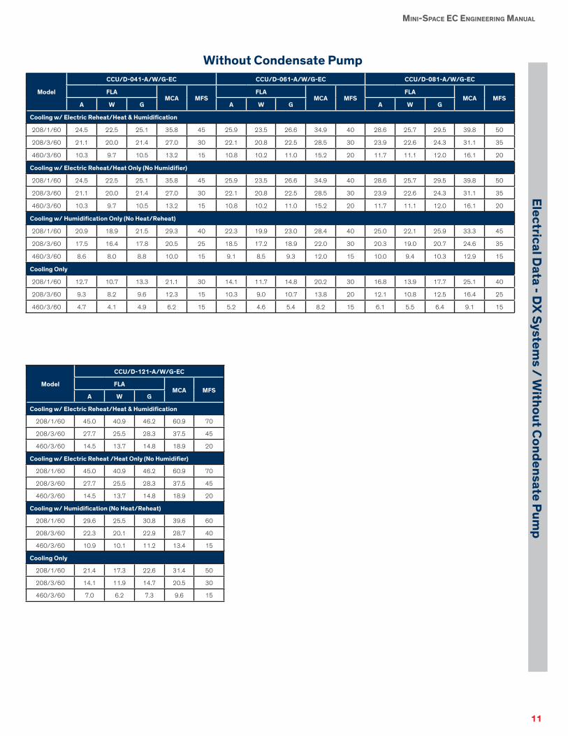
Electrical Data - DX Systems / Without Condensate Pump ........................................................11
Electrical Data - Chilled Water Systems / With and Without Condensate Pump .......................................12
Dimensional Data ................................... 13CCU/CCR-041/061/081/121-A, W, G-EC, & -110-C-EC .....................................................................13
CCD/CCF-041/061/081/121-A, W, G-EC & -110-C-EC .....................................................................14
Product Guide Specifi cations ............... 15SUMMARY .......................................................................15
DESIGN REQUIREMENTS ........................................15
QUALITY ASSURANCE ..............................................15
CABINET ..........................................................................15
Air Flow Patterns ...........................................................15
Up-Flow: ................................................ 15Down-Flow: ........................................... 15
Air Filtration .....................................................................15
MECHANICAL COMPONENTS ...............................15
Blower ...............................................................................15
Backward Inclined, Plenum Style Fan, with an EC Motor ................................................ 15
DX Refrigeration System ............................................15
Scroll Compressor .................................... 16
Evaporator Coil........................................ 16Snap-Acting Hot Gas Bypass (Optional).... 16Air-Cooled Heat Rejection........................ 16Water/Glycol Cooled Heat Rejection ........ 16
Chilled Water ................................................................... 16Cooling Coil ............................................ 16CW Control Valves .................................. 16
Steam Generating Humidifi er (Standard) .............. 16Dehumidifi cation Cycle (Standard) ........... 16
REHEAT ............................................................................ 16Electric Heat/ Reheat (Standard) ............... 16Hot Water/Steam Reheat/Heat (Optional) . 16Hot Gas Reheat (Optional) ....................... 17
ELECTRICAL SYSTEM ................................................17
Main Power Service Switch ...................... 17Remote Stop/Start Contacts..................... 17
AIR CONTROL ...............................................................17
EC Fan Speed Control ............................. 17E² SERIES CONTROLLER DESCRIPTION ...............................................................17
General ................................................... 17Field Confi gurable ................................... 17Password Protection ................................ 17Restorable Parameters/Factory Defaults .... 17Timer Feature .......................................... 18A/C Grouping pLAN Operation ................ 18BMS Interface (Optional).......................... 18Alarms .................................................... 18Controller Graphic Terminal ..................... 18
OPTIONAL FEATURES ...............................................18
Adjustable Floor Stand............................. 18Top Discharge Plenum Box (Up-fl ow units only) ........................................................ 18Condensate Pump ................................... 18Smoke Detection .................................... 18Firestat .................................................... 18Remote Water Detector- Spot Type .......... 18Remote Water Detector- Strip Type .......... 19Low Entering Condenser Water Kit .......... 19
CODE CONFORMANCE ............................................19
Table of Contents

iv
MINI-SPACE EC ENGINEERING MANUAL
Mod
el N
omen
clat
ure
Model Nomenclature
CCX-XXX-X-EC
CC Air Pattern Capacity (kW) Refrigerant Circuits Cooling Method Blower Type
Mini-Space Compact
System
D=Downfl ow
U=Upfl ow
R=Rear Return
F=Front Discharge
04
06
08
11
12
0
1
A=Air
W=Water
G=Glycol
C=Chilled Water
EC
Example:
12 kW capacity, downfl ow air pattern, 1 circuit, water-cooled DX, EC fans: CCD-121-W-EC

1
MINI-SPACE EC ENGINEERING MANUAL
Model N
omenclature G
uide Specifi cations
Model NomenclatureGuide Specifi cations
DX - EVAPORATOR SECTIONS
Air Cooled Remote Evaporator(Models CC( )-( )-A-EC)
The system shall be a remote (split) air cooled, fl oor mounted
precision air conditioner evaporator. The evaporator section shall
house, as a minimum, the evaporator coil, expansion valve, return
air fi lter, compressor, evaporator blower/motor and associated
electrical and refrigeration components.
The CC( )-( )-A-EC evaporator section shall be located
at some distance from its corresponding STULZ model
SCS-( )-( ) outdoor air cooled condenser.
The evaporator system shall require only a single point main
power supply connection; and the system shall ship from the
STULZ factory with a dry nitrogen holding charge ready for fi eld
refrigerant (R410A) charging.
DX - WATER COOLED SYSTEMS
Integral Self-Contained(Models CC( )-( )-W-EC)
The system shall be a self-contained, fl oor mounted precision air
conditioner to include integral water cooled, plate-fi n condenser
with factory installed head pressure water regulating control
valve(s). Condenser (source) water shall be provided by a cooling
tower or some other remote water source.
The system shall require only single point supply power connec-
tion and shall ship from the STULZ factory with a full operating
refrigerant (R410A) charge.
Water Regulating ValvesHead pressure shall be automatically controlled by a factory
installed 2-way water regulating valve rated for 600 psig wwp.
A 3-way valve is optionally available.
DX - GLYCOL COOLED SYSTEMS Integral Self-Contained(Models CC( )-( )-G-EC)
The system shall be a self-contained, fl oor mounted precision
air conditioner to include integral glycol cooled, plate-fi n con-
denser with factory installed head pressure glycol regulating
control valve(s). Condenser (source) glycol solution shall be
provided via a STULZ remote glycol pump package and dry-
cooler system.
The system shall require only a single point supply power
connection and shall ship from the STULZ factory with a full
operating refrigerant (R410A) charge.
Glycol Regulating ValvesHead pressure shall be automatically controlled by a factory
installed, 2-way glycol regulating valve rated for 600 psig wwp.
A 3-way valve is optionally available.
CHILLED WATER AIR HANDLERS Chilled Water System(Models CC( )-( )-C-EC)
The system shall be a fl oor mounted, chilled water precision
air conditioner to include chilled water cooling coil, evaporator
blower and motor and chilled water control valve. Chilled water
shall be provided by a remote liquid chiller system.
Chilled Water Control ValveCooling capacity shall be controlled with a factory installed
3-way modulating control valve rated for 600 psig. A 2-way
valve rated at 600 psig is optionally available.
Model NomenclatureGuide Specifi cations

2
MINI-SPACE EC ENGINEERING MANUAL
Prod
uct F
eatu
res
Inde
x
Mini-Space EC Model 041/061/081 110 121
SELECTED STANDARD FEATURES:
TEMPERATURE CONTROL
1-Stage Cooling Mode Standard Standard Standard
1-Stage Electric Reheating / Heating Standard Standard Optional
2-Stage Electric Reheating /Heating N/A N/A N/A
Cooling and/or Heating Only (No Humidity Control) Optional Optional Optional
HUMIDITY CONTROL
Electrode Canister Steam Humidifi er Standard Standard Standard
Dehumidifi cation Mode Electric Reheat Standard Standard Standard
CONTROLS
E2 Advanced Microprocessor w/ Alarms Standard Standard Standard
CABINET
Galvannealed Steel, Powder Coated Finish Standard Standard Standard
Insulated Stainless Steel Condensate Drain Pan Standard Standard Standard
2 lb/ft2 Density Thermal & Sound Insulation Standard Standard Standard
Floor Stand (Adjustable) Optional Optional Optional
FILTERS / PLENUMS
2”, 30% Avg. Eff. Pleated Filters Standard Standard Standard
2”, 60% Avg. Eff. Pleated Filters Optional Optional Optional
2- or 3-way Plenum Box (Up-Flow Units) Optional Optional Optional
DX-REFRIGERATION CIRCUIT
R410A Refrigerant Standard N/A Standard
Scroll Compressors Standard N/A Standard
Rotolock Service Valves Standard N/A Standard
High Effi ciency, Aluminum Fin / Copper Tube Coils Standard N/A Standard
Thermal Expansion Valves Standard N/A Standard
Refrigerant Sight Glasses & Filter/Drier Strainers Standard N/A Standard
BLOWERS / MOTORS
Backward Curved Direct Driven EC Standard Standard Standard
ELECTRICAL
1- or 3-phase Power Supply - - -- - - - - - See Electrical Tables Section - - - - - - - - - - - -
Multi-Voltage Control Transformer (24V Class 2) Standard Standard Standard
SAFETY FEATURES
E2 Visual Local & Remote Alarms Standard Standard Standard
Main Power Non-Fused Disconnect, unit mounted Standard Standard Standard
High / Low Refrigerant Pressure Switches (DX units) Standard Standard Standard
Motor Overload Protection Standard Standard Standard
SPECIFIC MODEL STANDARD FEATURES:
AIR COOLED
Low Ambient Head Pressure Control - - - - - - - - - -Two types: -20 °F or -30 °F*- - - - - - - - - -
Remote Air Cooled Condenser Standard N/A Standard
WATER / GLYCOL COOLED
2-way, 600 psig Water/Glycol Regulating Valves Standard N/A Standard
3-way, 600 psig Water/Glycol Regulating Valves Optional N/A Optional
Stainless Steel Brazed Plate Heat Exchanger Standard N/A Standard
CHILLED WATER SYSTEMS (CC( )-110-CW)
3-way, 600 psig Modulating Valve N/A Standard N/A
2-way, 600 psig Modulating Valve N/A Optional N/A
*Flooded head pressure control not available on all models.

3
MINI-SPACE EC ENGINEERING MANUAL
Model: CC( )-041-A-EC CC( )-061-A-EC CC( )-081-A-EC CC( )-121-A-EC
Evaporator Blower / Motor - Backward Curved EC
Nominal Motor Power, hp 1.3 1.3 1.3 1.3
Rated Air Flow, ft3/min @ 0.2 inH2O esp 1,180 1,180 1,180 1,890
Quantity of Blowers 1 1 1 1
Evaporator Coil - Aluminum Fin, Copper Tube
Rows (Face Area ft2) 4 (3.25) 4 (3.25) 4 (3.25) 4 (3.25)
Face Velocity, ft/min 363 363 363 581
Compressor - R-410A
Type (Quantity) Scroll (1) Scroll (1) Scroll (1) Scroll (1)
Input per Compressor, W 1,880 2,230 2,850 3,760
Total Heat of Rejection, kW (MBH) 8.6 (29.3) 10.1 (34.4) 12.4 (42.3) 16.6 (56.5)
Reheat/Heat - Performance Capacities Include Evaporator Blower Motor Heat
Electric Reheat / Heat (Standard)
Number of Stages 1 1 1 1
Total Nominal Capacity, kW (MBH) 3 (10.2) 3 (10.2) 3 (10.2) 6 (20.5)
Hot Gas Reheat (Optional)
Total Capacity, kW (MBH) 1.9 (6.4) 2.2 (7.6) 2.8 (9.7) 3.8 (12.8)
Hot Water Reheat / Heat (Optional) - Reheat Rated @ 180 °F Entering Water Temperature, EAT = 72 °F DB
Total Capacity, kW (MBH) 9.2 (31.5) 9.2 (31.5) 18.6 (63.5) 18.6 (63.5)
Flow Rate gpm (Pressure Drop, ftH2O) 3.2 (.7) 3.2 (.7) 6.5 (.8) 6.5 (.8)
Control Valve on/off on/off on/off on/off
Humidifi cation (Standard) - Electrode Steam Canister Humidifi er with Adjustable Output
Steam Output, lb/hr (Power Input, kW) 2–5 (1.7) 2–5 (1.7) 2–5 (1.7) 2–5 (1.7)
Std Control Cycling Cycling Cycling Cycling
Filters (Standard) - Disposable, MERV 8 Average Dust Spot Effi ciency
Up-fl ow, Front free return. Nom. Size (in.) (Quantity) 20 × 23 (1) 20 × 23 (1) 20 × 23 (1) 20 × 23 (1)
Up-fl ow, Rear-ducted return. Nom. Size (in.) (Quantity) 20 × 25 (1) 20 × 25 (1) 20 × 25 (1) 20 × 25 (1)
Down-fl ow. Nom. Size (in.) (Quantity) 20 × 23 (1) 20 × 23 (1) 20 × 23 (1) 20 × 23 (1)
Connection Sizes - Copper (Please refer to Mini-Space EC IOM Manual for proper interconnecting refrigerant line sizing.)
Liquid Line, in. OD (one per unit) 1/2 1/2 1/2 1/2
Hot Gas Line, in. OD (one per unit) 5/8 5/8 5/8 5/8
Condensate Drain, in. OD 7/8 7/8 7/8 7/8
Humidifi er Inlet, in. OD 1/4 1/4 1/4 1/4
Physical Data
Approximate Unit Weight, lb 450 450 450 480
Unit Dimensions, H in. x W in. x D in. CCU/D/F-( )-A 73 × 25 × 24 73 × 25 × 24 73 × 25 × 24 73 × 25 × 24
Unit Dimensions, H in. x W in. x D in. CCR-( )-A) 73 × 25 × 44 73 × 25 × 44 73 × 25 × 44 73 × 25 × 44
Shipping Dimensions, H in. x W in. x D in. CCU/D/F-( )-A 81 × 33 × 32 81 × 33 × 32 81 × 33 × 32 81 × 33 × 32
Shipping Dimensions, H in. x W in. x D in. CCR-( )-A) 81 × 33 × 52 81 × 33 × 52 81 × 33 × 52 81 × 33 × 52
Technical Specifi cations - Air C
ooled DX

4
MINI-SPACE EC ENGINEERING MANUAL
Tech
nica
l Spe
cifi c
atio
ns -
Wat
er C
oole
d D
X
Model: CC( )-041-W-EC CC( )-061-W-EC CC( )-081-W-EC CC( )-121-W-EC
Evaporator Blower / Motor - Backward Curved EC
Nominal Motor Power, hp 1.3 1.3 1.3 1.3
Rated Air Flow, ft3/min @ 0.2 inH2O esp 1,180 1,180 1,180 1,890
Quantity of Blowers 1 1 1 1
Evaporator Coil - Aluminum Fin, Copper Tube
Rows (Face Area ft2) 4 (3.25) 4 (3.25) 4 (3.25) 4 (3.25)
Face Velocity, ft/min 363 363 363 581
Compressor - R-410A
Type (Quantity) Scroll (1) Scroll (1) Scroll (1) Scroll (1)
Input per Compressor, W 1,510 1,810 2,580 3,020
Water Cooled Condenser - Plate-Finned (Based on 0% Glycol Solution)
Total Heat of Rejection, kW (MBH) 8.9 (30.4) 10.3 (35.2) 12.6 (43.1) 17.3 (58.9)
Flow Rate, gpm @ 85 °F EWT / 95 °F LWT 6.1 7.1 8.7 11.8
Total Unit Pressure Drop (ftH2O) 5.0 5.8 6.6 5.7
Reheat/Heat - Performance Capacities Include Evaporator Blower Motor Heat
Electric Reheat / Heat (Standard)
Number of Stages 1 1 1 1
Total Nominal Capacity, kW (MBH) 3 (10.2) 3 (10.2) 3 (10.2) 6 (20.5)
Hot Gas Reheat (Optional)
Total Capacity, kW (MBH) 1.4 (4.9) 1.7 (5.8) 2.2 (7.4) 2.9 (9.7)
Hot Water Reheat / Heat (Optional) - Reheat Rated @ 180 °F Entering Water Temperature, EAT = 72 °F DB
Total Capacity, kW (MBH) 9.2 (31.5) 9.2 (31.5) 18.6 (63.5) 18.6 (63.5)
Flow Rate, gpm (Pressure Drop, ftH2O) 3.2 (.7) 3.2 (.7) 6.5 (.8) 6.5 (.8)
Control Valve on/off on/off on/off on/off
Humidifi cation (Standard) - Electrode Steam Canister Humidifi er with Adjustable Output
Steam Output, lb/hr (Power Input, kW) 2–5 (1.7) 2–5 (1.7) 2–5 (1.7) 2–5 (1.7)
Std Control Cycling Cycling Cycling Cycling
Filters (Standard) - Disposable, MERV 8 Average Dust Spot Effi ciency
Up-fl ow, Front Free Return. Actual Size (in.) (Quantity) 20 × 23 (1) 20 × 23 (1) 20 × 23 (1) 20 × 23 (1)
Up-fl ow, Rear-ducted Return. Actual Size (in.) (Quantity) 20 × 25 (1) 20 × 25 (1) 20 × 25 (1) 20 × 25 (1)
Down-fl ow. Actual Size (in.) (Quantity) 20 × 23 (1) 20 × 23 (1) 20 × 23 (1) 20 × 23 (1)
Connection Sizes - Copper (Please refer to Mini-Space EC IOM Manual for proper interconnecting refrigerant line sizing.)
Condensate Drain, in. OD 7/8 7/8 7/8 7/8
Humidifi er Inlet, in. OD 1/4 1/4 1/4 1/4
Condenser In and Out, in. OD 7/8 7/8 7/8 7/8
Physical Data
Approximate Unit Weight, lb 480 480 480 510
Unit Dimensions, H in. x W in. x D in. CCU/D/F-( )-A 73 × 25 × 24 73 × 25 × 24 73 × 25 × 24 73 × 25 × 24
Unit Dimensions, H in. x W in. x D in. CCR-( )-A) 73 × 25 × 44 73 × 25 × 44 73 × 25 × 44 73 × 25 × 44
Shipping Dimensions, H in. x W in. x D in. CCU/D/F-( )-A 81 × 33 × 32 81 × 33 × 32 81 × 33 × 32 81 × 33 × 32
Shipping Dimensions, H in. x W in. x D in. CCR-( )-A) 81 × 33 × 52 81 × 33 × 52 81 × 33 × 52 81 × 33 × 52

5
MINI-SPACE EC ENGINEERING MANUAL
Model: CC( )-041-G-EC CC( )-061-G-EC CC( )-081-G-EC CC( )-121-G-EC
Evaporator Blower / Motor - Backward Curved EC
Nominal Motor Power, hp 1.3 1.3 1.3 1.3
Rated Air Flow, ft3/min @ 0.2 inH2O esp 1,180 1,180 1,180 1,890
Quantity of Blowers 1 1 1 1
Evaporator Coil - Aluminum Fin, Copper Tube
Rows (Face Area, ft2) 4 (3.25) 4 (3.25) 4 (3.25) 4 (3.25)
Face Velocity, ft/min 363 363 363 581
Compressor - R-410A
Type (Quantity) Scroll (1) Scroll (1) Scroll (1) Scroll (1)
Input per Compressor, W 2,020 2,390 3,050 4,040
Glycol Cooled Condenser - Plate-Finned (Based on 40% Ethylene Glycol Solution)
Total Heat of Rejection, kW (MBH) 8.5 (29.1) 10.1 (34.4) 12.2(41.7) 16.4 (56.1)
Flow Rate, gpm @ 85 °F EWT / 95 °F LWT 6.3 7.6 10.2 12.6
Unit Pressure Drop (ftH2O) 4.6 5.4 7.0 5.7
Reheat/Heat - Performance Capacities Include Evaporator Blower Motor Heat
Electric Reheat / Heat (Standard)
Number of Stages 1 1 1 1
Total Nominal Capacity, kW (MBH) 3 (10.2) 3 (10.2) 3 (10.2) 6 (20.5)
Hot Gas Reheat (Optional)
Total Capacity, kW (MBH) 2.0 (6.9) 2.4 (8.2) 3.0 (10.4) 4.0 (14.0)
Hot Water Reheat / Heat (Optional) - Reheat Rated @ 180 °F Entering Water Temperature, EAT = 72 °F DB
Total Capacity, kW (MBH) 9.2 (31.5) 9.2 (31.5) 18.6 (63.5) 18.6 (63.5)
Flow Rate, gpm (Pressure Drop, ftH2O) 3.2 (.7) 3.2 (.7) 6.5 (.8) 6.5 (.8)
Control Valve on/off on/off on/off on/off
Humidifi cation (Standard) - Electrode Steam Canister Humidifi er with Adjustable Output
Steam Output, lb/hr (Power Input, kW) 2–5 (1.7) 2–5 (1.7) 2–5 (1.7) 2–5 (1.7)
Std Control Cycling Cycling Cycling Cycling
Filters (Standard) - Disposable, MERV 8 Average Dust Spot Effi ciency
Up-fl ow, Front Free Return. Actual Size (in.) (Quantity) 20 × 23 (1) 20 × 23 (1) 20 × 23 (1) 20 × 23 (1)
Up-fl ow, Rear-ducted Return. Actual Size (in.) (Quantity) 20 × 25 (1) 20 × 25 (1) 20 × 25 (1) 20 × 25 (1)
Down-fl ow. Actual Size (in.) (Quantity) 20 × 23 (1) 20 × 23 (1) 20 × 23 (1) 20 × 23 (1)
Connection Sizes - Copper (Please refer to Mini-Space EC IOM Manual for proper interconnecting refrigerant line sizing.)
Condensate Drain, in. OD 7/8 7/8 7/8 7/8
Humidifi er Inlet, in. OD 1/4 1/4 1/4 1/4
Condenser In and Out, in. OD 7/8 7/8 7/8 7/8
Physical Data
Approximate Unit Weight, lb 480 480 480 510
Unit Dimensions, H in. x W in. x D in. CCU/D/F-( )-A 73 × 25 × 24 73 × 25 × 24 73 × 25 × 24 73 × 25 × 24
Unit Dimensions, H in. x W in. x D in. CCR-( )-A) 73 × 25 × 44 73 × 25 × 44 73 × 25 × 44 73 × 25 × 44
Shipping Dimensions, H in. x W in. x D in. CCU/D/F-( )-A 81 × 33 × 32 81 × 33 × 32 81 × 33 × 32 81 × 33 × 32
Shipping Dimensions, H in. x W in. x D in. CCR-( )-A) 81 × 33 × 52 81 × 33 × 52 81 × 33 × 52 81 × 33 × 52
Technical Specifi cations - Glycol C
ooled DX

6
MINI-SPACE EC ENGINEERING MANUAL
Model: CC()-041-W-EC CC()-061-W-EC CC()-081-W-EC CC()-121-W-EC
NET DX COOLING CAPACITY - (Includes Motor Heat @ Rated ft3/min & esp)
80 °F DB/62.9 °F WB, 38% RH, 52.3 °F DP
Total, kW (MBH) 7.5 (25.6) 8.6 (29.3) 10.4 (35.5) 13.7 (46.8)
Sensible, kW (MBH) 7.5 (25.6) 8.6 (29.3) 9.5 (32.4) 13.7 (46.8)
75 °F DB/61.1 °F WB, 45% RH, 52.3 °F DP
Total, kW (MBH) 6.9 (23.6) 8.3 (28.2) 10 (34.2) 13.4 (45.7)
Sensible, kW (MBH) 6.9 (23.6) 8.1 (27.5) 8.4 (28.8) 12.5 (42.7)
72 °F DB/60.0 °F WB, 50% RH, 52.3 °F DP
Total, kW (MBH) 7.1 (24.2) 7.9 (27.1) 9.7 (33.1) 13.1 (44.8)
Sensible, kW (MBH) 6.9 (23.4) 7.0 (24.0) 6.9 (23.6) 11.5 (39.1)
Model: CC()-041-A-EC CC()-061-A-EC CC()-081-A-EC CC()-121-A-EC
NET DX COOLING CAPACITY - (Includes Motor Heat @ Rated ft3/min & esp)
80° F DB/62.9 °F WB, 38% RH, 52.3 °F DP
Total, kW (MBH) 6.8 (23.2) 7.7 (26.1) 9.3 (31.7) 12.4 (42.2)
Sensible, kW (MBH) 6.8 (23.2) 7.7 (26.1) 9.1 (31.2) 12.4 (42.2)
75 °F DB/61.1 °F WB, 45% RH, 52.3 °F DP
Total, kW (MBH) 6.2 (21.2) 7.1 (24.1) 9.1 (31) 11.7 (39.8)
Sensible, kW (MBH) 6.2 (21.2) 7.1 (24.1) 8.2 (27.9) 11.4 (39.1)
72 °F DB/60.0 °F WB, 50% RH, 52.3 °F DP
Total, kW (MBH) 6.2 (21.3) 7.2 (24.4) 8.7 (29.7) 11.6 (39.5)
Sensible, kW (MBH) 6.2 (21.3) 7.1 (24.2) 7.2 (24.4) 11.3 (38.5)
Model: CC()-041-G-EC CC()-061-G-EC CC()-081-G-EC CC()-121-G-EC
NET DX COOLING CAPACITY - (Includes Motor Heat @ Rated ft3/min & esp)
80 °F DB/62.9°FWB, 38% RH, 52.3 °F DP
Total, kW (MBH) 6.6 (22.6) 7.4 (25.4) 8.9 (30.5) 12.0 (41.0)
Sensible, kW (MBH) 6.6 (22.6) 7.4 (25.4) 8.9 (30.5) 12.0 (41.0)
75 °F DB/61.1 °F WB, 45% RH, 52.3 °F DP
Total, kW (MBH) 6.0 (20.6) 6.9 (23.4) 8.6 (29.5) 11.3 (38.6)
Sensible, kW (MBH) 6.0 (20.6) 6.9 (23.4) 8.2 (28.1) 11.3 (38.6)
72 °F DB/60.0 °F WB, 50% RH, 52.3 °F DP
Total, kW (MBH) 5.9 (20.1) 7.0 (24.0) 8.4 (28.7) 11.2 (38.1)
Sensible, kW (MBH) 5.8 (19.9) 6.8 (23.1) 7.2 (24.6) 10.9 (37.3)
Perf
orm
ance
/Cap
acit
y D
ata
- A
/W/G

7
MINI-SPACE EC ENGINEERING MANUAL
Technical Specifi cations - Chilled W
ater
Model: CC( )-110-C-EC
Chilled Water Control Valve - Sized for Medium Flow @ 75 °F DB/62.5 °F WB EAT Conditions
3-way (standard) - Modulating
Size in. (Cv) ½ (5.0)
Valve Pressure Rating, psi 600
2-way (optional) - Modulating
Size in. (Cv) ½ (5.0)
Valve Pressure Rating, psi 600
Chilled Water Coil - Aluminum Fin, Copper Tube
Rows (Face Area, ft2) 4 (3.25)
Face Velocity, ft/min 581
Chilled Water Coil Blower / Motor - Backward Curved EC
Nominal Motor Power, hp 1.3
Rated Air Flow, ft3/min @ 0.2 inH2O esp 1,890
Quantity of Blowers 1
Reheat/Heat - Performance Capacities Include Evaporator Blower Motor Heat
Electric Reheat / Heat (Standard)
Number of Stages 1
Total Nominal Capacity, kW (MBH) 6 (20.5)
Hot Water Reheat / Heat (Optional) - Reheat Rated @ 180 °F Entering Water Temperature, EAT = 72 °F DB
Total Capacity, kW (MBH) 18.6 (63.5)
Flow Rate, gpm (Pressure Drop, ftH2O) 6.5 (.8)
Control Valve on/off
Humidifi cation (Standard) - Electrode Steam Canister Humidifi er with Adjustable Output
Steam Output, lb/hr (Power Input, kW) 2-5 (1.7)
Std Control Cycling
Filters (Standard) - Disposable, MERV 8 Average Dust Spot Effi ciency
Up-fl ow, Front Free Return. Actual Size (in.) (Quantity) 20 × 23 (1)
Up-fl ow, Rear-ducted Return. Actual Size (in.) (Quantity) 20 × 25 (1)
Down-fl ow. Actual Size (in.) (Quantity) 20 × 23 (1)
Connection Sizes - Copper (Please refer to Mini-Space EC IOM Manual for interconnecting refrigerant line sizing.)
Condensate Drain, in. OD 7/8
Humidifi er Inlet, in. OD 1/4
Water In and Out, in. OD 7/8
Physical Data
Approximate Unit Weight, lb 400
Unit Dimensions, H in. x W in. x D in. CCU/D/F-( )-A 73 × 25× 24
Unit Dimensions, H in. x W in. x D in. CCR-( )-A) 73 × 25× 44
Shipping Dimensions, H in. x W in. x D in. CCU/D/F-( )-A 81× 33 × 32
Shipping Dimensions, H in. x W in. x D in. CCR-( )-A) 81× 33 × 52

8
MINI-SPACE EC ENGINEERING MANUAL
Model: CC()-110-C-EC
NET COOLING CAPACITY @ 50 °F EWT, 0% Glycol Solution (Includes motor heat @ rated ft3/min & esp)
85° F DB/65.9 °F WB, 36% RH, 55 °F DP
High Flow(10°F ΔTw)
Total kW (MBH) 11.3 (38.7)
Sensible kW (MBH) 11.3 (38.7)
Flow Rate, gpm (Pressure Drop, ftH2O) 8.4 (20.8)
Med. Flow(12°F ΔTw)
Total kW (MBH) 10.6 (36.0)
Sensible kW (MBH) 10.6 (36.0)
Flow Rate, gpm (Pressure Drop, ftH2O) 6.6 (14.3)
Low Flow(14°F ΔTw)
Total kW (MBH) 9.8 (33.3)
Sensible kW (MBH) 9.8 (33.3)
Flow Rate, gpm (Pressure Drop, ftH2O) 5.3 (10.6)
80° F DB/64.2 °F WB, 42% RH, 55 °F DP
High Flow(10°F ΔTw)
Total kW (MBH) 9.1 (30.9)
Sensible kW (MBH) 9.1 (30.9)
Flow Rate, gpm (Pressure Drop, ftH2O) 6.8 (15.0)
Med. Flow(12°F ΔTw)
Total kW (MBH) 8.3 (28.3)
Sensible kW (MBH) 8.3 (28.3)
Flow Rate, gpm (Pressure Drop, ftH2O) 5.3 (10.6)
Low Flow(14°F ΔTw)
Total kW (MBH) 7.4 (25.3)
Sensible kW (MBH) 7.4 (25.3)
Flow Rate, gpm (Pressure Drop, ftH2O) 4.1 (7.7)
75 °F DB/62.5 °F WB, 50% RH, 55 °F DP
High Flow(10°F ΔTw)
Total kW (MBH) 6.8 (23.1)
Sensible kW (MBH) 6.8 (23.1)
Flow Rate, gpm (Pressure Drop, ftH2O) 5.3 (10.6)
Med. Flow(12°F ΔTw)
Total kW (MBH) 5.9 (20.1)
Sensible kW (MBH) 5.9 (20.1)
Flow Rate, gpm (Pressure Drop, ftH2O) 3.9 (7.3)
Low Flow(14°F ΔTw)
Total kW (MBH) 5.0 (17.0)
Sensible kW (MBH) 5.0 (17.0)
Flow Rate, gpm (Pressure Drop, ftH2O) 2.9 (5.5)
85 °F DB/64.5 °F WB, 32% RH, 52 °F DP
High Flow(10°F ΔTw)
Total kW (MBH) 11.3 (38.6)
Sensible kW (MBH) 11.3 (38.6)
Flow Rate, gpm (Pressure Drop, ftH2O) 8.4 (20.8)
Med. Flow(12°F ΔTw)
Total kW (MBH) 10.5 (36.0)
Sensible kW (MBH) 10.5 (36.0)
Flow Rate, gpm (Pressure Drop, ftH2O) 6.6 (14.3)
Low Flow(14°F ΔTw)
Total kW (MBH) 9.7 (33.2)
Sensible kW (MBH) 9.7 (33.2)
Flow Rate, gpm (Pressure Drop, ftH2O) 5.2 (10.4)
80° F DB/62.9 °F WB, 38% RH, 52 °F DP
High Flow(10°F ΔTw)
Total kW (MBH) 9.1 (30.9)
Sensible kW (MBH) 9.1 (30.9)
Flow Rate, gpm (Pressure Drop, ftH2O) 6.8 (15.0)
Med. Flow(12°F ΔTw)
Total kW (MBH) 8.2 (28.1)
Sensible kW (MBH) 8.2 (28.1)
Flow Rate, gpm (Pressure Drop, ftH2O) 5.2 (10.4)
Low Flow(14°F ΔTw)
Total kW (MBH) 7.4 (25.2)
Sensible kW (MBH) 7.4 (25.2)
Flow Rate, gpm (Pressure Drop, ftH2O) 4.1 (7.7)
75 °F DB/61.1 °F WB, 45% RH, 52 °F DP
High Flow(10°F ΔTw)
Total kW (MBH) 6.8 (23.0)
Sensible kW (MBH) 6.8 (23.0)
Flow Rate, gpm (Pressure Drop, ftH2O) 5.2 (10.4)
Med. Flow(12°F ΔTw)
Total kW (MBH) 5.9 (20.1)
Sensible kW (MBH) 5.9 (20.1)
Flow Rate, gpm (Pressure Drop, ftH2O) 3.9 (7.3)
Low Flow(14°F ΔTw)
Total kW (MBH) 5.0 (17.0)
Sensible kW (MBH) 5.0 (17.0)
Flow Rate, gpm (Pressure Drop, ftH2O) 2.9 (5.5)
Perf
orm
ance
Dat
a -
Chi
lled
Wat
er -
50 o F
EWT

9
MINI-SPACE EC ENGINEERING MANUAL
Model: CC()-110-C-EC
NET COOLING CAPACITY @ 45 °F EWT, 0% Glycol Solution (Includes motor heat @ rated ft3/min & esp)
85 °F DB/65.9 °F WB, 36% RH, 55 °F DP
High Flow(10°F ΔTw)
Total kW (MBH) 13.5 (46.1)
Sensible kW (MBH) 13.5 (46.1)
Flow Rate, gpm (Pressure Drop, ftH2O) 9.9 (27.3)
Med. Flow(12°F ΔTw)
Total kW (MBH) 12.7 (43.5)
Sensible kW (MBH) 12.7 (43.5)
Flow Rate, gpm (Pressure Drop, ftH2O) 7.8 (18.6)
Low Flow(14°F ΔTw)
Total kW (MBH) 11.9 (40.8)
Sensible kW (MBH) 11.9 (40.8)
Flow Rate, gpm (Pressure Drop, ftH2O) 6.3 (13.5)
80 °F DB/64.2 °F WB, 42% RH, 55 °F DP
High Flow(10°F ΔTw)
Total kW (MBH) 12.2 (41.7)
Sensible kW (MBH) 11.9 (40.5)
Flow Rate, gpm (Pressure Drop, ftH2O) 9.0 (23.4)
Med. Flow(12°F ΔTw)
Total kW (MBH) 10.5 (35.8)
Sensible kW (MBH) 10.5 (35.8)
Flow Rate, gpm (Pressure Drop, ftH2O) 6.5 (14.1)
Low Flow(14°F ΔTw)
Total kW (MBH) 9.7 (32.9)
Sensible kW (MBH) 9.7 (32.9)
Flow Rate, gpm (Pressure Drop, ftH2O) 5.2 (10.4)
75 °F DB/62.5 °F WB, 50% RH, 55 °F DP
High Flow(10°F ΔTw)
Total kW (MBH) 10.0 (34.2)
Sensible kW (MBH) 9.5 (32.4)
Flow Rate, gpm (Pressure Drop, ftH2O) 7.5 (17.5)
Med. Flow(12°F ΔTw)
Total kW (MBH) 8.2 (27.9)
Sensible kW (MBH) 8.2 (27.9)
Flow Rate, gpm (Pressure Drop, ftH2O) 5.2 (10.4)
Low Flow(14°F ΔTw)
Total kW (MBH) 7.3 (25.0)
Sensible kW (MBH) 7.3 (25.0)
Flow Rate, gpm (Pressure Drop, ftH2O) 4.0 (7.5)
85 °F DB/64.5 °F WB, 32% RH, 52 °F DP
High Flow(10°F ΔTw)
Total kW (MBH) 13.5 (46.0)
Sensible kW (MBH) 13.5 (46.0)
Flow Rate, gpm (Pressure Drop, ftH2O) 9.9 (27.3)
Med. Flow(12°F ΔTw)
Total kW (MBH) 12.7 (43.4)
Sensible kW (MBH) 12.7 (43.4)
Flow Rate, gpm (Pressure Drop, ftH2O) 7.8 (18.6)
Low Flow(14°F ΔTw)
Total kW (MBH) 11.9 (40.7)
Sensible kW (MBH) 11.9 (40.7)
Flow Rate, gpm (Pressure Drop, ftH2O) 6.3 (13.5)
80 °F DB/62.9 °F WB, 38% RH, 52 °F DP
High Flow(10°F ΔTw)
Total kW (MBH) 11.3 (38.6)
Sensible kW (MBH) 11.3 (38.6)
Flow Rate, gpm (Pressure Drop, ftH2O) 8.4 (20.9)
Med. Flow(12°F ΔTw)
Total kW (MBH) 10.5 (35.8)
Sensible kW (MBH) 10.5 (35.8)
Flow Rate, gpm (Pressure Drop, ftH2O) 6.5 (14.1)
Low Flow(14°F ΔTw)
Total kW (MBH) 9.6 (32.9)
Sensible kW (MBH) 9.6 (32.9)
Flow Rate, gpm (Pressure Drop, ftH2O) 5.2 (10.4)
75 °F DB/61.1 °F WB, 45% RH, 52 °F DP
High Flow(10°F ΔTw)
Total kW (MBH) 9.0 (30.8)
Sensible kW (MBH) 9.0 (30.8)
Flow Rate, gpm (Pressure Drop, ftH2O) 6.8 (15.1)
Med. Flow(12°F ΔTw)
Total kW (MBH) 8.2 (28.0)
Sensible kW (MBH) 8.2 (28.0)
Flow Rate, gpm (Pressure Drop, ftH2O) 5.2 (10.5)
Low Flow(14°F ΔTw)
Total kW (MBH) 7.3 (24.9)
Sensible kW (MBH) 7.3 (24.9)
Flow Rate , gpm (Pressure Drop, ftH2O) 4.0 (7.5)
Performance D
ata - Chilled W
ater - 45 oF EWT

10
MINI-SPACE EC ENGINEERING MANUAL
Model
CCU/D-041-A/W/G-EC CCU/D-061-A/W/G-EC CCU/D-081-A/W/G-EC
FLAMCA MFS
FLAMCA MFS
FLAMCA MFS
A W G A W G A W G
Cooling w/ Electric Reheat/Heat & Humidifi cation
208/1/60 26.4 24.4 27.0 37.7 45 27.8 25.4 28.5 36.8 45 30.5 27.6 31.4 41.7 50
208/3/60 23.0 21.9 23.3 28.9 30 24.0 22.7 24.4 30.4 35 25.8 24.5 26.2 33.0 40
460/3/60 11.1 10.5 11.3 14.0 15 11.6 11.0 11.8 16.0 20 12.5 11.9 12.8 16.9 20
Cooling w/ Electric Reheat/Heat Only (No Humidifi er)
208/1/60 26.4 24.4 27.0 37.7 45 27.8 25.4 28.5 36.8 45 30.5 27.6 31.4 41.7 50
208/3/60 23.0 21.9 23.3 28.9 30 24.0 22.7 24.4 30.4 35 25.8 24.5 26.2 33.0 40
460/3/60 11.1 10.5 11.3 14.0 15 11.6 11.0 11.8 16.0 20 12.5 11.9 12.8 16.9 20
Cooling w/ Humidifi cation Only (No Heat/Reheat)
208/1/60 22.8 20.8 23.4 31.2 40 24.2 21.8 24.9 30.3 40 26.9 24.0 27.8 35.2 50
208/3/60 19.4 18.3 19.7 22.4 25 20.4 19.1 20.8 23.9 30 22.2 20.9 22.6 26.5 35
460/3/60 9.4 8.8 9.6 10.8 15 9.9 9.3 10.1 12.8 15 10.8 10.2 11.1 13.7 15
Cooling Only
208/1/60 14.6 12.6 15.2 23.0 35 16.0 13.6 16.7 22.1 30 18.7 15.8 19.6 27.0 40
208/3/60 11.2 10.1 11.5 14.2 20 12.2 10.9 12.6 15.7 20 14.0 12.7 14.4 18.3 25
460/3/60 5.5 4.9 5.7 7.0 15 6.0 5.4 6.2 9.0 15 6.9 6.3 7.2 9.9 15
With Condensate Pump
Model
CCU/D-121-A/W/G
FLAMCA MFS
A W G
Cooling w/ Electric Reheat/Heat & Humidifi cation
208/1/60 46.9 42.8 48.1 62.8 70
208/3/60 29.6 27.4 30.2 39.4 45
460/3/60 15.3 14.5 15.6 19.7 20
Cooling w/ Electric Reheat /Heat Only (No Humidifi er)
208/1/60 46.9 42.8 48.1 62.8 70
208/3/60 29.6 27.4 30.2 39.4 45
460/3/60 15.3 14.5 15.6 19.7 20
Cooling w/ Humidifi cation (No Heat/Reheat)
208/1/60 31.5 27.4 32.7 41.5 60
208/3/60 24.2 22.0 24.8 30.6 40
460/3/60 11.7 10.9 12.0 14.2 20
Cooling Only
208/1/60 23.3 19.2 24.5 33.3 50
208/3/60 16.0 13.8 16.6 22.4 35
460/3/60 7.8 7.0 8.1 10.4 15
Ele
ctric
al D
ata
-DX
Sys
tem
s /
Wit
h C
onde
nsat
e Pu
mp
11
MINI-SPACE EC ENGINEERING MANUAL
Model
CCU/D-041-A/W/G-EC CCU/D-061-A/W/G-EC CCU/D-081-A/W/G-EC
FLAMCA MFS
FLAMCA MFS
FLAMCA MFS
A W G A W G A W G
Cooling w/ Electric Reheat/Heat & Humidifi cation
208/1/60 24.5 22.5 25.1 35.8 45 25.9 23.5 26.6 34.9 40 28.6 25.7 29.5 39.8 50
208/3/60 21.1 20.0 21.4 27.0 30 22.1 20.8 22.5 28.5 30 23.9 22.6 24.3 31.1 35
460/3/60 10.3 9.7 10.5 13.2 15 10.8 10.2 11.0 15.2 20 11.7 11.1 12.0 16.1 20
Cooling w/ Electric Reheat/Heat Only (No Humidifi er)
208/1/60 24.5 22.5 25.1 35.8 45 25.9 23.5 26.6 34.9 40 28.6 25.7 29.5 39.8 50
208/3/60 21.1 20.0 21.4 27.0 30 22.1 20.8 22.5 28.5 30 23.9 22.6 24.3 31.1 35
460/3/60 10.3 9.7 10.5 13.2 15 10.8 10.2 11.0 15.2 20 11.7 11.1 12.0 16.1 20
Cooling w/ Humidifi cation Only (No Heat/Reheat)
208/1/60 20.9 18.9 21.5 29.3 40 22.3 19.9 23.0 28.4 40 25.0 22.1 25.9 33.3 45
208/3/60 17.5 16.4 17.8 20.5 25 18.5 17.2 18.9 22.0 30 20.3 19.0 20.7 24.6 35
460/3/60 8.6 8.0 8.8 10.0 15 9.1 8.5 9.3 12.0 15 10.0 9.4 10.3 12.9 15
Cooling Only
208/1/60 12.7 10.7 13.3 21.1 30 14.1 11.7 14.8 20.2 30 16.8 13.9 17.7 25.1 40
208/3/60 9.3 8.2 9.6 12.3 15 10.3 9.0 10.7 13.8 20 12.1 10.8 12.5 16.4 25
460/3/60 4.7 4.1 4.9 6.2 15 5.2 4.6 5.4 8.2 15 6.1 5.5 6.4 9.1 15
Model
CCU/D-121-A/W/G-EC
FLAMCA MFS
A W G
Cooling w/ Electric Reheat/Heat & Humidifi cation
208/1/60 45.0 40.9 46.2 60.9 70
208/3/60 27.7 25.5 28.3 37.5 45
460/3/60 14.5 13.7 14.8 18.9 20
Cooling w/ Electric Reheat /Heat Only (No Humidifi er)
208/1/60 45.0 40.9 46.2 60.9 70
208/3/60 27.7 25.5 28.3 37.5 45
460/3/60 14.5 13.7 14.8 18.9 20
Cooling w/ Humidifi cation (No Heat/Reheat)
208/1/60 29.6 25.5 30.8 39.6 60
208/3/60 22.3 20.1 22.9 28.7 40
460/3/60 10.9 10.1 11.2 13.4 15
Cooling Only
208/1/60 21.4 17.3 22.6 31.4 50
208/3/60 14.1 11.9 14.7 20.5 30
460/3/60 7.0 6.2 7.3 9.6 15
Without Condensate Pump
Electrical Data - D
X System
s / Without C
ondensate Pump

12
MINI-SPACE EC ENGINEERING MANUAL
With Condensate Pump
ModelCCU/D-110-C-EC
FLA MCA MFSCooling w/ Electric Reheat/Heat & Humidifi cation
208/1/60 37.9 47.4 50
208/3/60 27.1 33.9 35
460/3/60 14.0 17.5 20
Cooling w/ Electric Reheat/Heat Only (No Humidifi er)208/1/60 29.7 37.1 40
208/3/60 18.9 23.6 25
460/3/60 10.1 12.6 15
Cooling w/ Humidifi cation Only (No Heat/Reheat)208/1/60 14.3 17.9 20
208/3/60 13.5 16.9 20
460/3/60 6.5 8.1 15
Cooling Only208/1/60 6.1 7.6 15
208/3/60 5.3 6.8 15
460/3/60 2.6 3.3 15
Without Condensate Pump
ModelCCU/D-110-C-EC
FLA MCA MFSCooling w/ Electric Reheat/Heat & Humidifi cation
208/1/60 36.0 45.0 45
208/3/60 25.2 31.5 35
460/3/60 13.2 16.5 20
Cooling w/ Electric Reheat/Heat Only (No Humidifi er)208/1/60 27.8 34.7 35
208/3/60 17.0 21.2 25
460/3/60 9.3 11.6 15
Cooling w/ Humidifi cation Only (No Heat/Reheat)208/1/60 12.4 15.5 20
208/3/60 11.6 14.5 15
460/3/60 5.7 7.1 15
Cooling Only208/1/60 4.2 5.2 15
208/3/60 3.4 4.2 15
460/3/60 1.8 2.3 15
Ele
ctric
al D
ata
- Chi
lled
Wat
er S
yste
ms
/ W
ith
and
Wit
hout
Con
dens
ate
Pum
p

13
MINI-SPACE EC ENGINEERING MANUAL
CCU/CCR-041/061/081/121-A, W, G-EC, & -110-C-EC
“Up-Flow” Front and Rear Return Vertical A/C(“Ducted” or optional “2- or 3-way plenum box”)
Dim
ensional Data
18.5"
22.6" 23.6"
72.8"
24.2"25.2"23.8" 22.7"
22.6" 23.6"23.6"
A
2.0"
Adjustable Floor Stand (Optional)
CCRCCU
Return
Return
Supply
Supply
DIMENSIONAL DATA - FLOOR STAND HEIGHTS
“A” DIMENSIONTURNING
VANENOMINAL HEIGHT
ADJUSTABLE HEIGHT
MAX MIN
4” upfl ow only 3.5” 4.5” Not available
6” 5.0” 7.0” Not available
12” 11.0” 15.0” Optional
15” 14.0” 18.0” Optional
18” 17.0” 21.0” Optional
24” 23.0” 26.0” Optional

14
MINI-SPACE EC ENGINEERING MANUAL
Dim
ensi
onal
Dat
a
DIMENSIONAL DATA - FLOOR STAND HEIGHTS
“A” DIMENSIONTURNING
VANENOMINAL HEIGHT
ADJUSTABLE HEIGHT
MAX MIN
4” upfl ow only 3.5” 4.5” Not available
6” 5.0” 7.0” Not available
12” 11.0” 15.0” Optional
15” 14.0” 18.0” Optional
18” 17.0” 21.0” Optional
24” 23.0” 26.0” Optional
CCD/CCF-041/061/081/121-A, W, G-EC & -110-C-EC
“Down-Flow” & Front Discharge Vertical A/C(“Free Return” or with optional “Ducted Return”)
23.8"
25.2"
22.7"24.2 "
72.8"
Return
22.6" 23.6"23.6"
A
2.0"
Supply
Supply
Return
CCDCCF
Adjustable Floor Stand (Optional)

15
MINI-SPACE EC ENGINEERING MANUAL
Product Guide Specifi cations
SUMMARYThis specifi cation describes requirements for a precision environ-
mental control system. The STULZ Mini-Space EC fl oor-mounted
air conditioning system shall provide precision temperature and/
or humidity control for computer rooms or rooms containing tele-
communications or other highly-sensitive heat load equipment
where continuous 24 hour a day, 365 days a year air conditioning
is required. Designed for front access, Mini-Space EC systems
require minimum fl oor space. The units are designed with a wide
range of options to handle both precision and comfort cooling
applications.
The Mini-Space EC model number shall be CC_-_ _ _-_-EC.
DESIGN REQUIREMENTSThe environmental control system shall be a Mini-Space EC
factory-assembled unit. The unit shall be designed for corner
installation, requiring front access through hinged front access
panels. No allowance for side service access shall be required.
Mini-Space EC units are especially adapted for both raised and
non-raised fl oors. The system shall be specifi cally designed for
high sensible heat ratio. Each system shall be capable of han-
dling ___ft3/min. The unit shall have a total cooling capacity
of ___BTU/H, and a sensible cooling capacity of ___BTU/H
based on entering air conditions of ___°F dry bulb and ___°F
wet bulb. The main fan motors shall be ___HP. The unit shall
have a power supply of ___volts.
QUALITY ASSURANCEThe manufacturer shall maintain a set of international standards
of quality management to insure product quality. Each system
shall be subjected to a complete operational and functional test
procedure at the factory prior to shipment.
CABINETAccess panels shall be fabricated from heavy gauge steel and shall
be securely attached to the frame. Access panels shall be powder
coated to match and provide corrosion protection. The panels
shall be lined with 1/2” (13 mm), 2 lb/ft2 (.90 kg), high-density
sound and thermal insulation and sealed with self-extinguishing
gasketing conforming to NFPA 90A and 90B.
STULZ Mini-Space EC4 –12 kW DX and CW
Floor Mounted Precision Air Conditioners
AIR FLOW PATTERNSUp-Flow: CCU-( )-( )-ECThe air conditioner shall be confi gured for an up-fl ow air pattern
with free evaporator return air through front fi ltered grille and
conditioned supply air through the top of the unit.
CCR-( )-( )-ECThe air conditioner shall be confi gured for an up-fl ow air pattern
with free evaporator return air through a rear fi ltered box and
conditioned supply air through the top of the unit.
Down-Flow: CCD-( )-( )-ECThe air conditioner shall be confi gured for a down-fl ow air pattern
with free evaporator return air to the top and conditioned supply
air discharge through the bottom of the A/C into the raised fl oor.
CCF-( )-( )-ECThe air conditioner shall be confi gured for a down-fl ow air pattern
with free evaporator return air to the top and conditioned supply
air discharge through the front of the A/C.
AIR FILTRATIONAll units shall be supplied with disposable air fi lters classifi ed
as UL 900 or UL 586. Filters shall be 2” deep (nominal). Filters
shall be pleated with a Minimum Effi ciency Reporting Value
(MERV) of 8.
Optional: Filters rated up to MERV 11, shall be available.
MECHANICAL COMPONENTS
BLOWERBackward Inclined, Plenum Style Fan, with an EC MotorThe blower shall be a direct driven, single inlet, two-fold back-
ward curved radial fan with an electronically commutated mo-
tor for maintenance free operation. The motor shall include:
integrated electronic control board and direct microprocessor
control signaling for fan speed control, soft-starting capabilities,
RS-485 BUS connection, and integrated current limitations.
Each fan shall be low noise, low vibration manufactured with
an anti-corrosive aluminum impeller. The fan impeller shall be
dynamically and statically balanced in two planes to minimize
vibration during operation.
DX REFRIGERATION SYSTEMAll refrigeration piping shall be refrigerant grade tubing. Each
refrigerant circuit shall include, as a minimum, refrigerant drier/
strainer, sight glass with moisture detector, thermal expansion
valve with rapid bleed port feature and external equalizer, evapo-
rator coil, compressor, high pressure switch with manual reset
and a low pressure switch with automatic reset.

16
MINI-SPACE EC ENGINEERING MANUAL
Prod
uct G
uide
Spe
cifi c
atio
nsSplit/Remote systems shall have a liquid line solenoid for refrig-
erant isolation to prevent liquid slugging. All high pressure joints
shall be brazed and the entire system shall be pressure tested at
the factory with dry nitrogen, evacuated to at least 50 microns
and fully charged with refrigerant.
Scroll CompressorThe compressor shall be a high effi ciency, high reliability and low
sound scroll compressor.
The compressor shall be complete with charging and service
Schrader ports, internal vibration isolation, internal thermal
overloads, internal pressure relief valve, internal discharge gas
vibration eliminator and external vibration mounting isolation.
Evaporator CoilEvaporator systems shall be configured for a draw-thru air
pattern to provide uniform air distribution over the evaporator
coil face. The coil shall be seamless drawn copper tubes, me-
chanically bonded to tempered aluminum fi ns with fi n pattern
designed for maximum heat transfer. Coil end plates shall be
hot dipped galvanized.
The evaporator coil shall be mounted in an insulated stainless
steel condensate drain pan.
Snap-Acting Hot Gas Bypass (Optional)The Mini-Space EC air conditioning system shall incorporate
a snap acting hot gas bypass system to provide modulation of
the unit’s cooling capacity and evaporator coil freeze protection
under low load conditions.
Air-Cooled Heat Rejection-20 °F, Variable Fan Speed ControlThe air cooled system shall incorporate a low ambient variable
speed fan head pressure control for year-found air condition-
ing system operation down to -20 °F DB minimum ambient air
temperature.
-30 °F, Flooded ControlThe air cooled system shall incorporate a low ambient fl ooded
head pressure control for year-round system operation down to
-30 °F DB minimum ambient air temperature.
This option shall include factory installed crankcase heaters,
cold-start relays, liquid refrigerant receivers with receiver liquid
level sight glass and head pressure regulating valves for fl ooded
condenser operation.
Water/Glycol Cooled Heat RejectionThe evaporator refrigerant circuit shall be provided with a fac-
tory installed single pass, counterfl ow confi gured brazed plate
heat exchanger, with integral subcooler, constructed of type
316 stainless steel; designed and tested for a 650 psig wwp.
2-Way, 600 psig Regulating ValveThe refrigerant circuit's head pressure shall be controlled by a
factory installed 2-way water / glycol regulating valve rated for
600 psig wwp.
3-Way, 600 psig Regulating Valve (Optional)The refrigerant circuit's head pressure shall be controlled by a
factory installed 3-way water / glycol regulating valve rated for
600 psig wwp.
CHILLED WATERCooling CoilThe chilled water cooling coil shall be constructed of seamless
drawn copper tubes, mechanically bonded to tempered alumi-
num fi ns for maximum heat transfer. Coil end plated shall be hot
dipped galvanized.
The cooling coil shall be mounted in an insulated aluminum
condensate drain pan.
CW Control ValvesChilled water cooling shall be controlled by the following standard
and optional control valves:
V1: 3-way, 600 psig (standard)
V2: 2-way, 600 psig (optional)
A ____-way modulating CW cooling control valve rated for a
maximum ______ psig wwp. shall be factory installed. Pre-
cision cooling control shall be accomplished via a modulating
control signal to the control valve.
STEAM GENERATING HUMIDIFIER (STANDARD)The humidifi er shall be a self-contained atmospheric steam gen-
erator. The humidifi er assembly shall include an integral fi ll cup,
fi ll and drain valves, disposable steam cylinder and associated
piping. The humidifi er shall be equipped with an auto adaptive
control system to optimize water conductivity, control automatic
drain/fl ush cycles, minimize energy waste and maximize cylin-
der life. Drain water tempered fi ll water shall insure drains do
not exceed 140 °F during operation. The humidifi er shall have
modulating output between 20% and 100% of rated capacity.
Note:The humidifi er is not available in units equipped with the Low
Entering Condenser Water kit option described on page 19.
Dehumidifi cation Cycle (Standard)The system shall be provided with a dehumidifi cation control
mode. Moisture is condensed on the cooling coil and discharged
through the condensate drain. Reheat shall be provided to offset
sensible cooling during the dehumidifi cation cycle.
REHEATElectric Heat/ Reheat (Standard)A factory mounted and wired low-watt density, plated fi n-tubular
design electric resistance heater shall be included to provide au-
tomatic sensible re-heating as required during the dehumidifi ca-
tion cycle and automatic heating mode. Electric heaters shall be
provided with miniature thermal/magnetic circuit breakers, which
shall protect each ungrounded conductor. Also included will be

17
MINI-SPACE EC ENGINEERING MANUAL
Product Guide Specifi cations
one automatic reset and one manual reset over-temperature
safety device (pilot duty).
Hot Water/Steam Reheat/Heat (Optional)A factory-installed, copper tube, aluminum fi n heat/reheat coil
and 2-way control valve shall be provided to control the fl ow
of hot water for automatic sensible reheating mode during the
dehumidifi cation cycle and automatic heating mode as required.
Hot Gas Reheat (Optional)(Models CC( )-( )-A, W, & G-EC only)A factory-installed copper tube, aluminum-fi n hot gas reheat
coil and valve shall be provided for automatic sensible reheating
mode during dehumidifi cation cycle. Hot compressor discharge
gas shall be diverted from the condenser to the hot gas reheat
coil providing energy-free sensible reheating.
ELECTRICAL SYSTEMThe electrical system shall conform to National Electrical Code
requirements. The control circuit shall be 24 volts AC, wired in
accordance with NEC Class II requirements. The control circuit
wire shall not be smaller than 18 AWG. All wiring shall be neatly
wrapped and routed in bundles. Each wire shall end with a service
loop and be securely fastened by an approved method. Each
wire in the unit shall be numbered for ease of service tracing.
All electrically actuated components shall be easily accessible
from the front of the unit without reaching over exposed high
voltage components or rotating parts. Each high voltage circuit
shall be individually protected by circuit breakers or manual motor
starters on all three phases. The blower motor shall have thermal
and short circuit protection. Line voltage and 24 volt control
circuit wiring shall be routed in separate bundles.
The electric box shall be positioned for service convenience and
shall include all the contactors, starters, fuses, circuit breakers,
terminal boards and control transformer required for operation
of the STULZ unit and shall allow for full service access.
Main Power Service SwitchThe Mini-Space EC shall be provided with a unit-mounted main
power service switch.
Remote Stop/Start ContactsIncluded in the system’s electrical control circuit shall be a 2-pin
terminal connection for remote stop/start of the Mini-Space EC
air conditioner by remote source.
AIR CONTROL
EC Fan Speed Control The system shall include a variable fan speed control package.
The unit’s controller shall permit control of the fan speed from
100% rated air volumetric fl ow rate to a user defi ne minimum fan
speed setting. Minimum and maximum fan speed settings shall
be user adjustable. User confi gured control sequences shall be
available for fan speed energy savings control.
E² SERIES CONTROLLER DESCRIPTION
GeneralThe advanced microprocessor based E² Series controller shall be
equipped with fl exible software capable of meeting the specifi c
needs of the application. The setpoints shall be default and their
ranges shall be easily viewed and adjusted from the user interface
display. The program and operating parameters shall be perma-
nently stored on a non-volatile system in the event of power failure.
The controller shall be designed to manage temperature and
relative humidity (RH) levels to a user defi ned setpoint via control
output signals to the system. Control parameters have variable
outputs from 0 to 100% of the full rated capacity.
The controller shall receive inputs for measurable control condi-
tions (temperature, relative humidity, and dew point) via return air
or room mounted sensors. The internal logic will then determine if
the conditions require cooling, humidifi cation or dehumidifi cation.
Control setpoints shall be established to maintain design condi-
tions of the installation. The controller will respond accordingly to
changes in these conditions and control the output/demand for
the appropriate mode of operation until user defi ned conditions
are achieved.
Field Confi gurableThe program for the E² Series controller shall be fi eld confi gu-
rable, allowing the operator to select control setpoints specifi c to
the application. Operator interface for the E² controller is provided
via a door mounted user interface graphic terminal. The graphic
terminal shall have a backlit LCD graphical display and function
keys giving the user complete control and monitoring capability
of the precision cooling system. The menu-driven interface shall
provide users the ability to scroll through and enter various menu
screens.
Password ProtectionAccess to the Info Menu, Alarms Log, and the ability to monitor
room conditions shall be allowed without the use of a password.
Modifi cations to the control setpoints shall require the use of
a password. The controller shall be programmed to recognize
predetermined security levels before allowing access to input
screens containing critical variables. Three secured menu levels
(Control, Service and Factory) will support unique passwords that
must be entered to access the menu screens so only authorized
personnel may perform modifi cations to the settings.
Restorable Parameters/Factory DefaultsUpon initial start-up the system shall operate using the setpoints
programmed by the factory. The customer may enter new oper-
ating parameters in the Control menu and the system will then
operate accordingly. The new setpoints may be stored as “Cus-
tomer Default Setpoints.” The primary setpoints entered by the
factory still remain stored in the controller's memory as “Factory
Setpoints.” The setpoints for the system may be re-adjusted in the
Control menu at any time. If it becomes necessary, the customer
may restore the setpoints back to the Customer Default setpoint
values or to the original Factory setpoint values.

18
MINI-SPACE EC ENGINEERING MANUAL
OPTIONAL FEATURESMini-Space EC fl oor-mounted air conditioning system stan-
dard features can be deleted and/or substituted with optional
features to allow you the fl exibility to select the confi guration
best suited for your application.
Adjustable Floor StandAn adjustable fl oor stand shall be provided to allow instal-
lation of the Mini-Space EC fl oor-mounted air conditioning
system onto a raised fl oor environment. Floor stand height
shall be adjustable. The fl oor stand shall ship separately for
fi eld installation.
Top Discharge Plenum Box (Up-fl ow units only)A 2- or 3-way plenum discharge box shall be provided. The
plenum box shall include double-defl ecting, adjustable grilles.
The plenum box shall ship separately for rigging purposes.
Condensate PumpA condensate pump for automatic removal of condensate and
humidifi er fl ush water (if applicable) shall be shipped loose
for fi eld installation in the Mini-Space EC fl oor-mounted air
conditioning system. The condensate pump shall include an
internal overfl ow safety fl oat which, when wired to the Mini-
Space EC unit’s remote stop/start terminals, shall open the
unit’s control circuit, thereby shutting the unit down in the
event of a condensate overfl ow. The condensate pump shall
be specifi cally designed to operate with the higher conden-
sate temperatures caused by the fl ush and drain cycle of the
electrode canister humidifi er.
Smoke Detection A photo-electric smoke detector shall be factory installed
and wired in the return air section of the Mini-Space EC fl oor-
mounted air conditioning system. The photo-electric detector
shall include built-in circuitry that performs a functional test of
all detection circuits at least once every 40 seconds without
the need for generating smoke. The UL listed velocity range
shall be 0-3000 fm. The air conditioner will shut down upon
sensing smoke in the return air stream.
FirestatThe Mini-Space EC fl oor-mounted air conditioning system
shall be provided with a factory wired and mounted fi restat.
The fi restat will shut down the air conditioner upon sensing a
high return air temperature.
Remote Water Detector- Spot TypeA remote single point water/leak detector shall be factory
supplied and shall ship separately for fi eld installation. Upon
sensing a water leak, the normally closed water detector con-
trol circuit shall open, thereby shutting down the Mini-Space
EC floor-mounted air conditioning unit’s water producing
components.
Timer FeatureA timer shall allow the user to set up an operating schedule to
automatically scale back or shut down the air conditioner during
low demand or unoccupied periods. This is an energy saving fea-
ture offering the user the ability to create an operating schedule
tailored to the needs of the building. An evening (night-setback)
schedule may also be created, allowing the system to operate at
night with relaxed temperature/humidity setpoints and offsets.
A/C Grouping pLAN OperationMultiple Mini-Space EC E² controllers shall be able to be con-
nected (grouped) to a pLAN local network, allowing the com-
munication of data and information from each controller to a
central control terminal or Lead controller. The Lead controller
display screens can be used to monitor and adjust group control
variables for the individual system controllers. Each E² controller
connected to the pLAN network shall be identifi ed with its own
unique address.
Multiple Mini-Space EC systems consisting of up to eight STULZ
precision air conditioners equipped with like controllers may be
controlled and monitored via the E² controller. With multiple
STULZ Mini-Space EC systems each unit can selectively be
confi gured as “Active” to operate as a primary A/C, “Capacity As-
sist” for staged operation, or as “Standby” to come online in case
of a failed air conditioning unit to ensure continuous availability.
The controller may also be confi gured to rotate units with timed
duty cycling to promote equal run-time and assure that each
Mini-Space EC system within the rotating group is operationally
exercised on a periodic timed basis.
BMS Interface (Optional)The E² series controller shall incorporate a 10 Mbps communi-
cation interface port that can be fi eld connected through a serial
interface to a Building Management System via Modbus, BACnet,
SNMP, or HTTP as confi gured by the factory. A controller inter-
faced to a network must be confi gured for BMS communication.
AlarmsAlarm conditions shall activate a red LED indicator that back-
lights the alarm function key. As an option, an alarm condition
may also be enunciated by an audible alarm signal. An alarm is
acknowledged by pressing the alarm key. This calls up alarm
display screens that provide a text message detailing the alarm
conditions. After an alarm condition is corrected, the alarm can
be cleared by pressing the alarm key.
Controller Graphic TerminalThe graphic terminal features a character-based liquid-crystal
display with adjustable contrast and LED illuminated function
keys. The screens that appear on the graphic terminal display
present data that originates from the controller.
The controller shall be operated via the graphic terminal keypad.
The controller software provides an alarm log and four menu
levels to the operator: Information, Control, Service, and Factory.
These menus shall permit the user to easily view, control, and
confi gure operating parameters for the Mini-Space EC system.
Prod
uct G
uide
Spe
cifi c
atio
ns -
Opt
ions
19
MINI-SPACE EC ENGINEERING MANUAL
Product Guide Specifi cations
SELECTED OPTIONSRemote Water Detector- Strip TypeA 20 ft in length remote strip/cable type water/leak detector
shall be provided for remote fi eld installation. In addition to the
20 ft sensing cable, a 24 volt water detector power module shall
require fi eld mounting and wiring to the factory provided termi-
nal connection. Upon sensing a water leak, the normally closed
water detector control circuit shall open, thereby shutting down
the Mini-Space EC fl oor-mounted air conditioning unit’s water
producing components.
Low Entering Condenser Water KitFor Water/Glycol systems that require entering condenser water
temperatures from 65 °F to 45 °F, the system shall be provided
with a factory installed in-line liquid refrigerant receiver to help
reduce the negative effect the low condenser source can have
on the evaporator. A compressor crankcase heater shall also be
provided standard with this option.
CODE CONFORMANCEIntertek Laboratory (an NRTL) listed and labeled in compli-ance with UL 1995 and CSA C22.2 No. 236.

STULZ North American Headquarters
QE
CC
02
5B
A
pri
l 20
17
� ©
ST
UL
Z U
SA
– S
pe
cifi
ca
tio
ns
sub
jec
t to
ch
an
ge
wti
ho
ut
no
tic
e.
www.stulz-usa.com
STULZ AIR TECHNOLOGY SYSTEMS (STULZ USA) , INC.1572 Tilco Drive | Frederick, MD 21704
Tel: 301.620.2033 | Fax: 301.662.5487 | [email protected]
STULZ Company Headquarters
STULZ GmbHHolsteiner Chaussee 283
22457 Hamburg
STULZ Subsidiaries
STULZ Australia Pty. Ltd.34 Bearing Road
Seven Hills NSW 21 47
STULZ Austria GmbH
Industriezentrum NÖ – SÜD,
Straße 15, Objekt 77, Stg. 4, Top 7
2355 Wiener Neudorf
STULZ Belgium BVBATervurenlaan 34
1040 Brussels
STULZ Brasil Ar Condicionado Ltda.Rua Cancioneiro de Évora, 140
Bairro - Santo Amaro São
Paulo-SP, CEP 04708-010
STULZ España S.A. Avenida de los Castillos 1034
28918 Leganés (Madrid)
STULZ France S. A. R. L. 107, Chemin de Ronde
78290 Croissy-sur-Seine
STULZ S.p.A. Via Torricelli, 3
37067 Valeggio sul Mincio (VR)
STULZ-CHSPL (India) Pvt. Ltd.006, Jagruti Industrial Estate
Mogul Lane, Mahim
Mumbai - 400 016
STULZ México S.A. de C.V. Avda. Santa Fe No. 170
Oficina 2-2-08, German Centre
Delegación Alvaro Obregon
MX- 01210 México
Distrito Federal
STULZ GROEP B. V. Postbus 75
180 AB Amstelveen
STULZ New Zealand Ltd. Office 71, 300 Richmond Rd.
Grey Lynn, Auckland
STULZ Polska SP. Z O.O. Budynek Mistral.
Al. Jerozolimskie 162
02 – 342 Warszawa
STULZ Singapore Pte Ltd. 33 Ubi Ave 3 #03-38 Vertex
Singapore 408868
STULZ Air Technology and Services Shanghai Co., Ltd. Room 406, Building 5
457 North Shanxi Road
Shanghai 200040
STULZ South Africa Pty. Ltd.Unit 3, Jan Smuts Business Park
Jet Park, Boksburg
Gauteng, South Africa
STULZ U. K. Ltd. First Quarter,
Blenheim Rd. Epsom
Surrey KT 19 9 QN