subaru brz toyota gt86 scion fr-s...map switching method of operation the map switching feature is...
TRANSCRIPT

Subaru BRZ
Toyota GT86
Scion FR-S
Version 10 RaceROM Manual

BRZ RaceROM Guide
Version 0.32 Last Modified 18-Jul-18 Page 2
Copyright © 2017 EcuTek Technologies Ltd
Contents 1. Warning ................................................................................................................................................................ 3
2. Introduction .......................................................................................................................................................... 4
Feature list ................................................................................................................................................................ 4
Supported Vehicle Models ....................................................................................................................................... 4
Availability ................................................................................................................................................................. 4
3. Updates ................................................................................................................................................................ 5
Summary of updates ................................................................................................................................................ 5
Further updates have been made to existing features ............................................................................................. 6
4. Features ............................................................................................................................................................... 7
Map Switching .......................................................................................................................................................... 7
Launch Control Feature ............................................................................................................................................ 9
Flat Foot Shifting Feature (MT Models Only) ......................................................................................................... 11
Accelerator Trim ..................................................................................................................................................... 12
Auto Blip Feature .................................................................................................................................................... 13
Boost Control .......................................................................................................................................................... 15
Closed Loop Fuel Control ....................................................................................................................................... 30
FlexFuel .................................................................................................................................................................. 35
Sensors .................................................................................................................................................................. 41
Speed Density ........................................................................................................................................................ 47
5. Custom Maps ..................................................................................................................................................... 52
Introduction ............................................................................................................................................................. 52
6. RaceROM Logging ............................................................................................................................................. 56
Logging Speed Improvements ............................................................................................................................... 56
7. What’s not supported ......................................................................................................................................... 57
Old Model ROMs .................................................................................................................................................... 57

BRZ RaceROM Guide
Version 0.32 Last Modified 18-Jul-18 Page 3
Copyright © 2017 EcuTek Technologies Ltd
1. Warning
!!! CAUTION !!!
EcuTek ProECU tuning tools should only be used by experienced tuners who understand the
product and engine calibration.
If you do not fully understand this product then you WILL damage your engine, ECU or your
vehicle.
Please ensure you fully read all EcuTek manuals BEFORE attempting to use ProECU with your
laptop or your vehicle.
Use with extreme caution and understanding at all times, if in doubt then do not proceed.
EcuTek accepts no responsibility for any damage to the engine, ECU or any part of the vehicle
that results directly or indirectly from using the product.
** If you are in any doubt that you do NOT have the experienced required to use this product
then you should NOT USE IT **
Retail customers
** If you have any doubt that you do NOT have the experienced required to use this product
then you should NOT USE IT, you should simply contact your EcuTek Master Tuner shown
clearly on the top of your Programming Kit or visit your preferred tuning shop to have a
professional tuner to use it for you **

BRZ RaceROM Guide
Version 0.32 Last Modified 18-Jul-18 Page 4
Copyright © 2017 EcuTek Technologies Ltd
2. Introduction
EcuTek RaceROM is a package of special software features that can be installed into the ECU of the supported
vehicles. You simply open your ECU ROM file using EcuTek software, apply the RaceROM Feature File (Patch) to
it, adjust the RaceROM maps as necessary, and then program the ROM file into the vehicle.
Please read the ProECU Tuning RaceROM Feature File Guide for info on how RaceROM works, how to install
and uninstall RaceROM feature files, and further hints and tips.
Please also see our website for various videos and webinars for further information.
Feature list
EcuTek RaceROM for Subaru BRZ currently includes the following features:
• Map Switching**
• Speed Density**
• Flex Fuel**
• Boost Control**
• Custom Sensor Import**
• Closed Loop Fuel Control**
• Custom Maps**
• Launch Control
• Flat Foot Shifting
• Downshift Auto Blip
• Accelerator Trim
• Per Gear Rev Limits
NOTE: Features marked ** are only available to trade customers, or retail customers that have purchased the
optional RaceROM BRZ upgrade package from their Master Tuner.
Supported Vehicle Models
This product supports Subaru BRZ, Toyota GT86 and Scion FR-S models in all worldwide markets. Please note
that this manual might refer to all of the above models as just the Subaru BRZ.
We have similar products are available for other vehicles. Please contact our sales team for further details.
Availability
EcuTek RaceROM Feature Files (RRFF) will be made available via EcuTek Update, always use the latest RRFF
version that is in the RaceROM folder.

BRZ RaceROM Guide
Version 0.32 Last Modified 18-Jul-18 Page 5
Copyright © 2017 EcuTek Technologies Ltd
3. Updates
This latest RaceROM is built on the previous Version 9 release and builds on the core features with significant new
features.
Summary of updates
This latest RaceROM update has the following additional features;
Boost Control
• Flex Fuel integration for target and limit
• Separate high/low altitude wastegate base duty maps
• Overall enable RPM below which wastegate solenoid is disabled
• Boost control activation based on VVT status
• Safety limits for boost target
• WG base duty multiplier for Gear/IAT
• Throttle based boost limit per MapSwitch Mode
Custom sensor input definition
• PI Fuel Pressure Sensor
• Coolant Pressure Sensor
• FlexFuel Sensor
• Wideband O2 Sensor
• Define min and max voltages to detect failed sensor
• Set default value for failed sensors
• Adjustable sensor filtering
Closed loop Full Load Fuel Control
• Closed loop control
• Enable per Map switch mode
• Easy to tune
FlexFuel
• Optionally define a pre-determined ethanol content override per map switch mode
• Sensor smoothing
• Sensor output freezing to combat fluctuations caused be aerated fuel
• Ignition Offset map
• Fuel Multiplier map
• AFR Target offset map
• Separate live data values for actual sensor output (which may vary with inadequate fuel systems) and the
ethanol content carried forward into the FlexFuel strategy (which may be fixed due to load thresholds or per
Map switch mode).

BRZ RaceROM Guide
Version 0.32 Last Modified 18-Jul-18 Page 6
Copyright © 2017 EcuTek Technologies Ltd
Further updates have been made to existing features
Custom Maps
Added many new Inputs for custom maps
• AFR – Actual (n:1)
• AFR – Target (n:1)
• AFR – Wideband (n:1)
• Boost Target (Bar)
• Clutch Pedal
• Coolant Pressure (bar)
• Fuel Pressure (Bar)
• Ethanol Content (%)
• Gear Shift Sensor
• Ignition Timing Final (º)
• Injector open Time DI (ms)
• Injector open Time PI (ms)
• Knock Correction (º)
• Lateral G (g)
• Launch RPM (RPM)
• Launch RPM Error (RPM)
• VVT Exhaust Angle(º)
• VVT Intake Angle(º)
• VVT Intake Error (º)
• Wheel Slip (%)
Added New Outputs for custom maps
• Boost Target
• Torque Actual
• SD Volumetric Efficiency
Added the axis selection criteria function for easy safeguards
• Added separate Deactivation timer
Speed Density
• Added Atmospheric Pressure Compensation
• Added the ability to blend MAF and SD airflow calculation for better transitions

BRZ RaceROM Guide
Version 0.32 Last Modified 18-Jul-18 Page 7
Copyright © 2017 EcuTek Technologies Ltd
4. Features
Map Switching
Method of Operation
The Map Switching feature is enabled by the option buttons in the ‘Map Switch Options' map. Four modes are
allowed by default, but this can be reduced if desired.
In “Mode 1”, the ECU will use the original ECU maps for Fuelling, Base Ignition Timing and Ignition Advance.
In the other three modes, the ECU will use the new Fuel, and Ignition Timing maps labelled Mode2, Mode3 and
Mode4 as appropriate.
Currently, the ECU does not always remain in the chosen mode when the ignition is turned off. We hope to develop
a solution to this problem. In the interim, you should always check the current mode when starting the vehicle.
Switching mode using the cruise control stalk
• Ignition must be ON
• Ensure cruise control master switch is OFF
• Pull the cruise lever towards you (i.e. cancel position) and hold for 1 second.
• The tachometer will move to 1000, 2000, 3000 or 4000 rpm to indicate the currently active mode.
• Move the cruise lever up (res/acc position) to increase the mode.
• Move the cruise lever down (set/cst position) to decrease the mode.
• Save the selected mode by pulling the cruise lever towards you (cancel position) or waiting 3 seconds.
Switching mode using the accelerator and defog switch
The driver can switch modes by turning on the rear window demist switch while holding the accelerator to the floor.
Every time you do this, the mode increases by 1. After mode 4, it goes back to mode 1.
The check engine light will flash to indicate which mode has been set: One flash for mode 1, two flashes for mode
2, three flashes for mode 3, etc.

BRZ RaceROM Guide
Version 0.32 Last Modified 18-Jul-18 Page 8
Copyright © 2017 EcuTek Technologies Ltd
Switching mode using the traction and stability control switches
When this option is selected, the ECU maps are selected depending on the vehicle's traction and stability settings.
• Mode 1 - Traction Control on, VSC Normal
• Mode 2 - Traction Control on, VSC Sport
• Mode 3 - Traction Control off, VSC Normal
• Mode 4 - Traction Control off, VSC Sport
Switching mode using the Automatic Transmission Mode
When this option is selected, the ECU maps are selected depending on the Automatic Transmission setting.
• Mode 1 - Normal
• Mode 2 - Sport
• Mode 3 - Snow
• Mode 4 - Manual
Integration with Launch Control, Flat Foot Shifting and Auto Blip
The Launch Control, Flat Foot Shifting and Auto Blip features can be independently enabled in each of the four
modes.
Logging
The “Mapswitch Mode” diagnostic parameter can be used to log the current map switch mode.

BRZ RaceROM Guide
Version 0.32 Last Modified 18-Jul-18 Page 9
Copyright © 2017 EcuTek Technologies Ltd
Launch Control Feature
The Launch Control feature limits maximum RPM during launch to help control wheel spin and allow the fastest
possible take off.
Live Data Parameters
• Launch RPM – Launch control RPM setpoint
• Launch RPM Error – Difference between current RPM and the Target, positive is over target
• LFA State – Diagnostic status info for LC, FFS and AutoBlip, for use by EcuTek support
Map List
Method of Operation
Activate the launch control as follows:
• Ensure the ‘Launch Control Enable’ checkbox is ON for the current Map Switch Mode
• Engine must be running and Vehicle must be stationary
• Press clutch pedal and move the gear stick to 1st position
• Quickly press the accelerator all the way to the floor
• Adjust launch RPM using the cruise control stalk
• Release the clutch to commence launch
When Launch Control is active, the rev limit will be set to the ‘Launch Control Rev Limit’. This limit defaults to the
'Launch Control Rev Limit Base" value and can be adjusted up and down using the cruise control stalk. Select
"Res/Acc" to increase the launch RPM and "Set/Cst" to decrease it. An alternative method of adjustment is
available for vehicles without cruise control.
During the launch, the rev limit increases according to the 'Launch Control Rev Limit Delta, This 2D map, indexed
by elapsed time, has multiple columns to allow you to set up a multi-stage system for best results.
Adjustments are provided that allow you to richen the AFR and retard the timing when the vehicle is stationary in
order to create pops and bangs. This adjustment is removed as soon as the vehicle starts to move.
The Launch Control feature is deactivated when one of the following conditions occurs:

BRZ RaceROM Guide
Version 0.32 Last Modified 18-Jul-18 Page 10
Copyright © 2017 EcuTek Technologies Ltd
• The elapsed time exceeds the last column on the ‘Launch Control Rev Limit Delta Map’
• The driver lifts off the accelerator
• The driver performs a flatfoot shift
Integration with Map Switching Feature
The Launch Control Feature can be enabled in any
of the four calibration modes by selecting the
appropriate checkboxes in the “Enable Special
Features” map.
Vehicles without cruise control
Set the launch control rev limit as follows:
• Ensure the ‘Launch Control Enable’ checkbox is ON for the current Map Switch Mode
• Engine must be running and Vehicle must be stationary
• Turn on rear window demist switch
• Press clutch
• Rev engine and hold at desired launch RPM
• Turn off rear window demist switch
• Check engine light will flash to indicate that new limit has been saved.
Vehicles with automatic transmission
(Due to the operation of the automatic transmission, we do not advise you use the Launch Control feature)
Activate the launch control as follows:
• Ensure the ‘Launch Control Enable’ checkbox is ON for the current Map Switch Mode
• Engine must be running and Vehicle must be stationary
• Press brake pedal and move the gear stick to a forward position
• Quickly press the accelerator all the way to the floor
• Adjust launch RPM using the cruise control stalk
• Release the brake to commence launch
Ensure that the launch RPM is below the stall speed of the torque converter.

BRZ RaceROM Guide
Version 0.32 Last Modified 18-Jul-18 Page 11
Copyright © 2017 EcuTek Technologies Ltd
Flat Foot Shifting Feature (MT Models Only)
Map List
Method of Operation
The Flat Foot Shifting Feature (FFS) is activated when all of the following conditions are met:
• ‘The Flat Foot Shift Enable’ checkbox is ON for the current Map Switch Mode
• The vehicle is travelling faster than the ‘Flat Foot Shift Minimum Speed’
• The accelerator amount is greater than the value in the ‘Full Accelerator Threshold Map’
• The driver is pressing the Clutch pedal
As the Flat Foot Shifting feature activates, a temporary rev limit is set that is slightly higher than the current RPM.
The ignition timing is retarded by a specified amount that reduces engine torque while preventing the RPM from
rising too rapidly. When the driver completes the gear change, the temporary rev limit and timing adjustment are
removed.
The Flat Foot Shifting Feature is cancelled when one of the following conditions occurs:
• The driver releases the Clutch pedal
• The driver lifts off the accelerator
• The vehicle speed falls below the value in the ‘Flat Foot Shift Minimum Speed Map’
An AFR adjustment is provided that allows you to enrichen the mixture during the shift. The richer AFR cannot be
measured from the exhaust gas due to the operation of the rev limiter.
Integration with Map Switching Feature
The Flat Foot Shift Feature can be enabled each of the four modes by selecting the appropriate checkboxes in the
“Enable Special Features” map.

BRZ RaceROM Guide
Version 0.32 Last Modified 18-Jul-18 Page 12
Copyright © 2017 EcuTek Technologies Ltd
Accelerator Trim
Map List
Method of Operation
The Accelerator trim map allows you to adjust the accelerator response by intercepting the accelerator position
signal and replacing it with a different value. This can improve drivability in vehicles that do not respond to pedal
input in a linear fashion.
Integration with Map Switching Feature
There is a separate Accelerator Trim map for each of the four modes. You can therefore calibrate the vehicle with
different accelerator response in each mode.

BRZ RaceROM Guide
Version 0.32 Last Modified 18-Jul-18 Page 13
Copyright © 2017 EcuTek Technologies Ltd
Auto Blip Feature
The Auto Blip feature applies a short burst of throttle when the driver is down-shifting under braking. This raises the
RPM to keep the engine operating within its power band and provides a smooth entry into the lower gear by reducing
engine braking.
Map List
AutoBlip Minimum Speed
Vehicle speed that must be exceeded for AutoBlip to be enabled.
AutoBlip Pedal Percentage
The x axis is time since Autoblip was triggered (described below). Autoblip ends when the maximum time on the X
axis is exceeded. Be careful to avoid using too much Accel at low RPM as this will cause the car to push on
aggressively.
Method of Operation
The Auto Blip feature is activated when all of the following conditions are met:
• The ‘Auto Blip Enable checkbox’ is ON for the current Map Switch Mode
• The vehicle is travelling faster than the Auto Blip Minimum Speed
• The driver presses the brake pedal, followed by the clutch pedal
The accelerator blip is immediately cancelled when one of the following conditions occurs:
• The driver releases the Brake Pedal
• The driver releases the Clutch Pedal
• The vehicle speed falls below the ‘Auto Blip Minimum Speed’
• The Auto Blip timer reaches the end of the map

BRZ RaceROM Guide
Version 0.32 Last Modified 18-Jul-18 Page 14
Copyright © 2017 EcuTek Technologies Ltd
Timeline
When the driver down-shifts while braking, the ECU will blip the accelerator. The amount of accelerator to apply
and the duration of the blip is controlled by the ‘AutoBlip Pedal Percentage Map’ as shown in the diagram below,
this is a 2D slice through the 3D map.
Note: Auto Blip is not available on vehicles fitted with Automatic Transmissions.
Integration with Map Switching Feature
The Auto Blip Feature can be enabled each of the 4 modes by selecting the appropriate checkboxes in the “Enable
Special Features” map.

BRZ RaceROM Guide
Version 0.32 Last Modified 18-Jul-18 Page 15
Copyright © 2017 EcuTek Technologies Ltd
Boost Control
Introduction
The EcuTek BRZ boost control is based on the proven strategy used in GT-R RaceROM Phase 6. We recommend
tuners use RaceROM boost control as it now has its own full set of dedicated maps so you no longer have to
create a large number of custom maps. Upon adding a version 10 or later RRFF, this option is enabled by a simple
check box, and comes pre-populated with some sensible values that should allow good control after a little tuning.
Absolute Boost
Boost control uses Manifold Absolute Pressure throughout. Please ensure you are familiar with the concept of
the absolute pressure before tuning the boost control. Remember that a target of 1.0 is close to sea-level
atmospheric pressure and not positive boost.
Live Data Parameters
• Boost Error – Difference between MAP and Boost Target, positive numbers are over boost
• Boost Target – Absolute pressure target in bar, measured by the intake manifold pressure sensor
• Manifold Absolute Pressure – Absolute pressure in bar, measured by the intake manifold pressure sensor
• Wastegate Duty – The duty cycle applied to the wastegate solenoid (Same as Final Duty)
• WG Duty Base – Output from Wastegate Duty Base maps
• WG Duty Adder – Correction resulting from Gear/IAT multiplier step
• WG Duty Integral – WG duty added by Integral correction of EcuTek boost control strategy
• WG Duty Proportional – WG duty added by Proportional correction of EcuTek boost control strategy

BRZ RaceROM Guide
Version 0.32 Last Modified 18-Jul-18 Page 16
Copyright © 2017 EcuTek Technologies Ltd
Map List
Boost Control Options
Boost Control Enable
To start using EcuTek’s hard coded boost control strategy simply enable the boost control strategy in the desired
modes. When enabled the CPC solenoid is hijacked, otherwise the duty is defined by the normal CPC strategy.
Boost Control Map Smoothing
The output of the MAP sensor can be smoothed for the purposes of boost control.
Boost Control Options
Boost Control Active Only when VVT enabled
Boost Limit Maps
The Boost Limit maps are active even when boost control is not enabled, this is so that supercharged cars can
make use of the boost limit functions without driving the CPC solenoid. Set this to the maximum allowed boost
actual so it can limit the boost by driving the throttle closed.
The strategy will hijack the accel pedal and close the throttle to the Boost limit accel cut set point.
If a hard fuel cut is required a custom map will need to be used.

BRZ RaceROM Guide
Version 0.32 Last Modified 18-Jul-18 Page 17
Copyright © 2017 EcuTek Technologies Ltd
Boost Limit – Ethanol
The Boost limit is a 3D map in absolute pressure that when the MAP exceeds this setpoint for the Boost Limit Time
Delay.
Boost Limit – Gasoline
The Boost limit is a 3D map in absolute pressure that when the MAP exceeds this setpoint for the Boost Limit Time
Delay.
Boost Limit – Flexfuel Blend
Boost Limit Delay
Time period in milliseconds the ECU will wait before triggering a fuel cut when the manifold relative pressure
exceeds the boost limit as set by the boost limit maps and boost limit blend map.
Boost Limit Hysteresis
When the boost has dropped below the hysteresis value it will then allow the throttle to open again.

BRZ RaceROM Guide
Version 0.32 Last Modified 18-Jul-18 Page 18
Copyright © 2017 EcuTek Technologies Ltd
Boost Target Maps
Boost target limit maps allow you to limit the boost target per map switch mode and gear at different RPM. This will
allow you to have per gear per mode target boost settings that can be used for different scenarios like drag track
and street.
Boost Target – Ethanol
Boost target used when the output of the Boost Target – Flexfuel Blend map is 1.0
Boost Target – Gasoline
Boost target used when the output of the Boost Target – Flexfuel Blend map is 0.0
Ethanol Content
Atmo Pressure
Gear
ECT
Coolant Temp
Boost Target Mode/Gear Limiter
Boost Target ECT Multiplier
Boost Target Accel/Mode Multiplier
Boost Target - Flexfuel Blend
Boost Target - Gasoline
LIMIT
X
Boost Target - Ethanol
Engine RPM
Blend
Initial Boost Target
Boost Target
MS Mode
ECTBoost Target ECT Multiplier
EOTBoost Target EOT Multiplier
IAMBoost Target IAM Multiplier
IATBoost Target IAT Multiplier
+Engine RPM
Boost Target Atmo/RPM Adder
Atmo Pressure
Engine RPM
Gear
Custom Maps Processing

BRZ RaceROM Guide
Version 0.32 Last Modified 18-Jul-18 Page 19
Copyright © 2017 EcuTek Technologies Ltd
Boost Target – Flexfuel Blend
The Boost Target map is set using torque demand and engine speed, the output is in absolute pressure. This map
should be set to match the maximum desired boost at the maximum torque demand, you can then limit the boost
target in by mode using the Target limit maps or custom maps. The value is put through all of the compensation,
custom maps and limiter maps before it is processed by the wastegate correction functions.
Boost target Accel/Mode Multiplier
Boost Target Atmo/RPM Adder
The boost target can be offset for changes in atmospheric pressure the default map values reduce the absolute
boost target 0.1Bar for each 0.1Bar drop in atmospheric pressure. This is suitable for small turbos which will often
be pushed to their maximum at sea level, and pushing the same absolute pressure at altitude can be detrimental to
the turbos while not giving the desired pressure.
If working with turbos that have plenty of headroom at sea level then flattening this map to 0 will give the same
absolute pressure target at altitude, and result in similar power levels at varying altitude.

BRZ RaceROM Guide
Version 0.32 Last Modified 18-Jul-18 Page 20
Copyright © 2017 EcuTek Technologies Ltd
Boost Target ECT Muliplier
The output of the map multiplies the boost target based on Engine Coolant Temperature and can be used to
prevent significant boost being targeted during warmup, or in an over-temperature condition.
As boost target will have an impact on the WG duty selected, there is no need to also adjust WG duty cycle based
on ECT, or any of the inputs used by similar maps.
Boost Target EOT Multiplier
Used in a similar way to the ECT baesd multiplier this map multiplies the boost target based on Engine Oil
Temperature and can be used to prevent significant boost being targeted during warmup, or in an over-temperature
condition.
For cars used on track that may experience higher than normal oil temperatures this may want some adjustment
based on what is considered “normal” for the car being tuned.

BRZ RaceROM Guide
Version 0.32 Last Modified 18-Jul-18 Page 21
Copyright © 2017 EcuTek Technologies Ltd
Boost Target IAT Multiplier
For Intake / charge air temperature correction (depending on sensor position) to reduce the target if the air or
charge temperature is high and high boost will introduce control issues and spark knock.
Boost Target IAM Multiplier
For Ignition advance multiplier value. This will reduce the boost target if the advance multiplier is low due to poor
quality fuels or non-ideal running conditions.
Boost Target Mode/Gear Limiter
The final boost target is limited by this map and serves as an easy way to cap the boost target to a specific level
based on MapSwitch Mode.

BRZ RaceROM Guide
Version 0.32 Last Modified 18-Jul-18 Page 22
Copyright © 2017 EcuTek Technologies Ltd
Wastegate Control Maps
Once a boost target is calculated, it’s passed to the wastegate control strategy which tries to keep the boost on
target. Use the boost target maps to select your target and only use the WG maps to maintain the target.
Once active (over RPM and MAP thresholds) the wastegate duty is controlled as per the following diagram.
Wastegate Activation Manifold Pressure
The wastegate solenoid will be deactivated until Manifold Absolute Pressure exceeds this value. This is used to
stop the noise from a chattering solenoid valve in conditions that boost cannot be realistically controlled.
Wastegate Activation RPM
The wastegate solenoid remain off until this engine speed is exceeded.
Atmo Pressure
Boost Target
Wastegate Integral Step
WG Base - Altitude Blend
WG Base - High Altitude
X
WG Base - Low Altitude
Engine RPM
Blend
WG Duty Base
WG Duty Final
Boost Error
WG Duty Gear/IAT Multiplier
+Engine RPM
Wastegate Proportional
Boost Error
Engine RPM
Boost Target
Custom Maps Processing
IAT
Gear
WG Duty Proportional
+WG Duty Integral+

BRZ RaceROM Guide
Version 0.32 Last Modified 18-Jul-18 Page 23
Copyright © 2017 EcuTek Technologies Ltd
Wastegate Base (high altitude)
Wastegate Base (low altitude)
This is a normal WG duty % output for specific RPM’s and boost target. This can be tuned as per any other WG
duty base map and it uses the corrected and compensated final target boost value (including custom maps). To
account for the different responses when at varying altitudes we have added a high-altitude map (when baro / atmo
pressure is less than sea level e.g.0.850bar).
If you were to tune the WG duty to achieve the desired boost at the maximum and minimum altitudes the car will
see you would then set the blend map to 1 at low altitudes (use 100% of low altitude map) and 0 at high altitudes
(use 0% of low altitude map and 100% of high altitude map).
Wastegate Base Altitude Blend
This map defines how the high and low altitude base maps are combined to produce the wastegate base duty. A
value of 1.0 uses only the value from the low altitude (sealevel) base map, a value of 0.0 uses only the value from
the high altitude base map. The final value for WG Duty Base is calculated as:
𝑊𝐺 𝐷𝑢𝑡𝑦 𝐵𝑎𝑠𝑒 = (𝑊𝐺 𝐵𝑎𝑠𝑒 𝐷𝑢𝑡𝑦 (𝑙𝑜𝑤 𝑎𝑙𝑡𝑖𝑡𝑖𝑑𝑒) × 𝑊𝐺 𝐵𝑎𝑠𝑒 𝐴𝑙𝑡𝑖𝑡𝑢𝑑𝑒 𝐵𝑙𝑒𝑛𝑑)
+ (𝑊𝐺 𝐵𝑎𝑠𝑒 𝐷𝑢𝑡𝑦 (ℎ𝑖𝑔ℎ 𝑎𝑙𝑡𝑖𝑡𝑖𝑑𝑒) × (1 − 𝑊𝐺 𝐵𝑎𝑠𝑒 𝐴𝑙𝑡𝑖𝑡𝑢𝑑𝑒 𝐵𝑙𝑒𝑛𝑑))
The example shown below uses the high altitude base map at 0.85 bar atmospheric pressure and the low altitude
base map at 1.00 bar atmospheric pressure with linear interpolation in between.
This give a smooth adjustable blend between two easily calibrated maps hopefully speeding up the tuning process.

BRZ RaceROM Guide
Version 0.32 Last Modified 18-Jul-18 Page 24
Copyright © 2017 EcuTek Technologies Ltd
Wastegate Gear / IAT Multiplier
WG duty will need to be adjusted to compensate for the changes in air density due to intake air temperature
increases or decreases. The pear gear axis will help to accommodate the different way the load is introduced in
different gears allowing you to use higher duty to spool the turbo better without over boosting in higher gears.
There is no need to reduce WG duty at high Intake temperatures for safety reasons. This important safety feature
should be dealt with by adjusting the boost target using the Boost Target IAT Multiplier map. Adjust the boost you
want using the target maps, and use the WG duty maps and compensations to ensure you hit that target.
WG Integral Correction
The Integral correction amount is calculated per cycle and added onto the final value for duty it’s based on boost
error and the output is duty cycle % the integral will build more slowly to offset any boost error working with the
proportional control. Integral control can suffer from wind up when its employed during spool up when the actual
boost error is large so there are a series of thresholds to prevent windup and limits while still maintaining adequate
corrections.
Wastegate Integral Boost Error Activation
To prevent integral wind up issues creating over-correction of WG duty a threshold has been added based on
boost error, as the base WG duty decreases the boost error to the top value of the map, when the boost error
reaches this the integral is set to start (provide the other thresholds are met as well), if the boost error continues to
increase to below the lower value the integral function will switch off to prevent further wind up.

BRZ RaceROM Guide
Version 0.32 Last Modified 18-Jul-18 Page 25
Copyright © 2017 EcuTek Technologies Ltd
Wastegate Integral Manifold Pressure Activation
It has been found that a single MAP switch point was not enough to get adequate control of boost at altitude so a
2D map was introduced to use an atmospheric pressure adjustment to the MAP switch on threshold for the integral
function. this allows you to start using integral correction for boost pressure earlier at higher altitudes.
Wastegate Integral Manifold Pressure Hysteresis
To prevent integral activation improperly switching on and off as the boost pressure oscillates around the threshold
a hysteresis value is applied to the 2D map value for activation. this means that the MAP must drop below the
threshold set in the MAP activation threshold minus this hysteresis value (so if activation is at 1.3 bar deactivation
will occur at 1.1bar with a hysteresis of 0.2bar.
Wastegate Integral Min/Max
Can be used to limit ow much influence the integral correction can apply and is useful in limiting integral windup.
Wastegate Integral Throttle Activation
These must all be exceeded before the integral correction is applied the top values are the activation point and the
bottom values are the deactivation points.
Wastegate Proportional
The output of this map is applied instantaneously to the WG duty output channel to correct for under and over
boost conditions. The boost error value is in bar and there is specific logging parameter for the boost error and the
proportional outputs.
BRZ RaceROM Guide
Version 0.32 Last Modified 18-Jul-18 Page 26
Copyright © 2017 EcuTek Technologies Ltd
Getting started with boost control
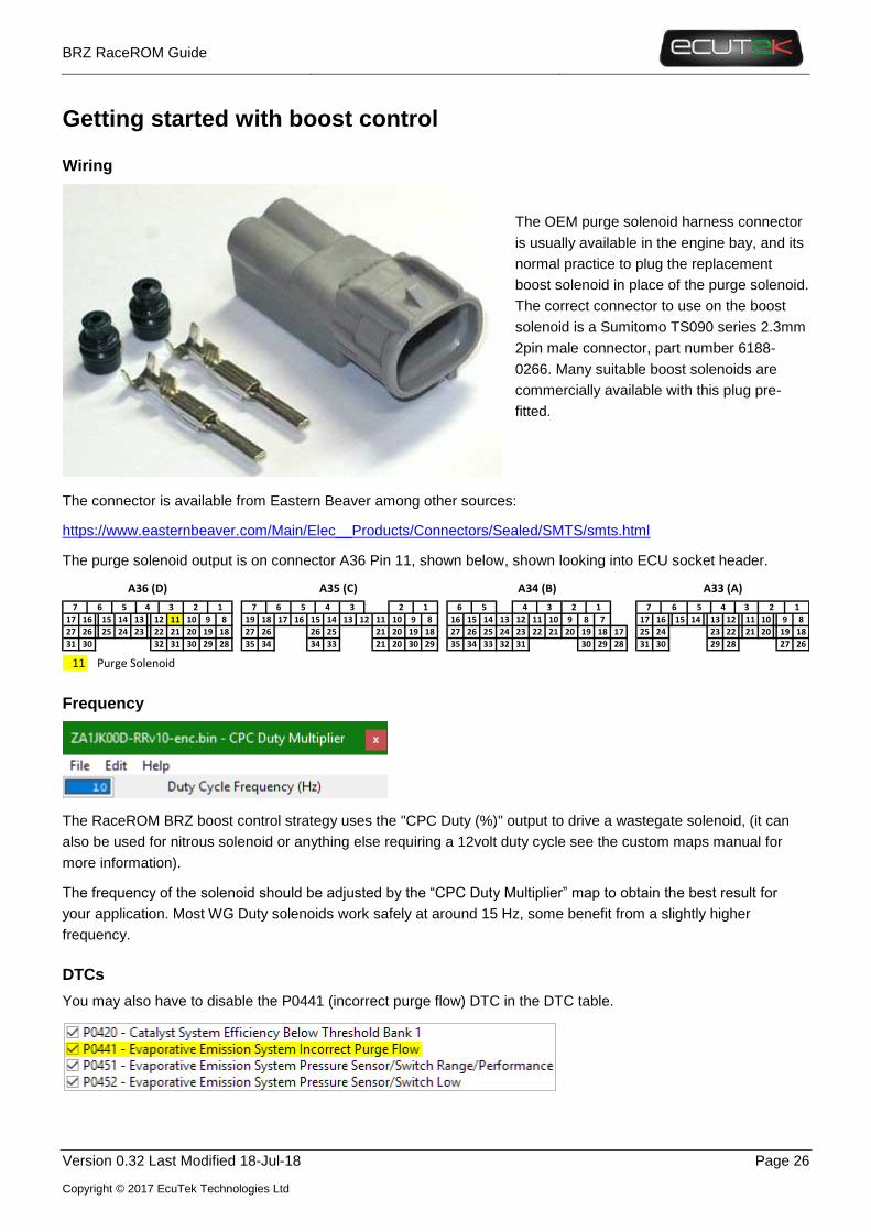
Wiring
The OEM purge solenoid harness connector
is usually available in the engine bay, and its
normal practice to plug the replacement
boost solenoid in place of the purge solenoid.
The correct connector to use on the boost
solenoid is a Sumitomo TS090 series 2.3mm
2pin male connector, part number 6188-
0266. Many suitable boost solenoids are
commercially available with this plug pre-
fitted.
The connector is available from Eastern Beaver among other sources:
https://www.easternbeaver.com/Main/Elec__Products/Connectors/Sealed/SMTS/smts.html
The purge solenoid output is on connector A36 Pin 11, shown below, shown looking into ECU socket header.
Frequency
The RaceROM BRZ boost control strategy uses the "CPC Duty (%)" output to drive a wastegate solenoid, (it can
also be used for nitrous solenoid or anything else requiring a 12volt duty cycle see the custom maps manual for
more information).
The frequency of the solenoid should be adjusted by the “CPC Duty Multiplier” map to obtain the best result for
your application. Most WG Duty solenoids work safely at around 15 Hz, some benefit from a slightly higher
frequency.
DTCs
You may also have to disable the P0441 (incorrect purge flow) DTC in the DTC table.
14 11 15 14 11 10
24 21 21 20
31
11 Purge Solenoid
A35 (C) A33 (A)A34 (B)
13
23
5
A36 (D)
2930
7 6 3
17 16 9
1927 26 22
31 30 32 35 34 21 20
7 6
19 18 17
27 2618
28
8
25 20
1012
2 1
15
30 29
20 19 18
34 33
26 25 21
1
14 12 11 10 9 8
30 29
17
28
21 20 19 18
35 34 33 32 31
10 9 8 7
27 26 25 24 23 22
16 15 14 13 12 11
4 3 2 15 4 2
27 26
4
13
23
29
12
22
28
3
31 30
3 12
25 24 19 18
6
8913
7 56
17 1616 15
54

BRZ RaceROM Guide
Version 0.32 Last Modified 18-Jul-18 Page 27
Copyright © 2017 EcuTek Technologies Ltd
Valves
There are Subaru OEM and aftermarket valve options.
Subaru OEM 2 port
A Subaru 2 port solenoid (part no.16102AA360) was used for our testing and plugs directly into the CPC valve
wiring. This valve will require a flow restrictor and 2 port specific control plumbing.
This should be run at no more than 15Hz.
A 3 port version should be used when wider ranges of control are
required, the Subaru solenoid (part no. 16102AA013).
COBB Tuning EBCS
https://www.cobbtuning.com/products/subaru-wrx-sti-fxt-3-port-boost-control-solenoid-bcs
This is ased on a MAC valve, complete with the correct electrical
connector and a basic bracket. This should be run around 25Hz for
best results.
GrimmSpeed EBCS
Based on a MAC valve and should be run around 25Hz for best results.
http://www.grimmspeed.com/electronic-boost-control-solenoid-3-port-subaru-06-07-wrx-04-07-sti-04-08-fxt/
Like the COBB valve this is also based on a MAC valve, complete
with the correct electrical connector and a selection of bracket
options. This should be run around 25Hz for best results.

BRZ RaceROM Guide
Version 0.32 Last Modified 18-Jul-18 Page 28
Copyright © 2017 EcuTek Technologies Ltd
Pierburg 3 port
This valve is a common OEM valve and typically comes with a Tyco Junior Timer male plug, and requires a patch
loom. This valve was employed by Prodrive in UK as part of the upgrade applied to the Impreza WR1 special
edition. This valve can be used at frequencies as high as 35Hz.
Initial Tuning
Assuming the targets are reasonable well defined, the difficult part is usually to get the actual boost to reach the
target and stay on target without significant correction and minimal fluctuation. If you have no idea of the boost
control setup for your target vehicle, below is a guide to get you started.
1. Adjust base wastegate duty
• Do initial tests with default proportional and integral setup to get started, use mapswitching to
change targets on-the-fly.
• Assume 10% duty at WG base pressure.
• Assume 50% duty at max target boost (this will be adjusted later)
• Test target at just above base so the solenoid is having an effect, for example if base pressure at
0% is 1.5bar absolute start testing at 1.6 bar target.
• Test again with a slightly higher target (eg +0.2 bar) to obtain approximate slope for base WG map
• Use slope data to estimate base WG values at max boost target before testing. For example, if
1.6bar absolute stabilized at 20% and 1.8 bar stabilized at 30%, a 5% increase per 0.1bar of boost
target will give a good starting point.
2. Adjust proportional response
• If boost and proportional duty oscillate noticeably, start by reducing the proportional values to
approximately 70% of the previous values and retest.
• Don’t fine tune the proportional map on the first test, wait until the base WG maps and integral
have been tuned from the default values as both influence the proportional response.
• If response is “good” then the proportional can be fine-tuned, including for RPM.
3. Adjust Integral response
• Adjust activation error to reduce windup
• Adjust step values to increase speed of integral response (unlikely to be significant)
4. Fine tune base wastegate duty
• Look at the trends and think about what the turbo would do in a steady-state condition. Don’t use
very high base values to try and improve spoolup at low RPM below the normal boost threshold.
• Look at what duty is required to hit the target boost and use this to guide the values in the base
maps. For example, if the boost is on target at 2.0 bar absolute, and the WG Duty Final is 45% with
then this can be used to update the base WG duty for 2.0 bar absolute
• If there is a boost error, also look at what boost is achieved for the current duty cycle. For example,
if the boost target is 2.0 bar absolute, and the WG duty is steady at 25% but the Manifold Absolute
Pressure is only 1.8 bar, you have good data to set the WG base duty for 1.8 bar.
• Combine quality data at known points of boost and duty to shape the whole map, and return to
step 1, fine tuning values at different boost targets and RPM ranges.
BRZ RaceROM Guide
Version 0.32 Last Modified 18-Jul-18 Page 29
Copyright © 2017 EcuTek Technologies Ltd
Although this may seem like a long process, it can also be done while testing fuelling and ignition and once the
base WG values are within 5-10% the integral correction values give good data on how to adjust the base maps.
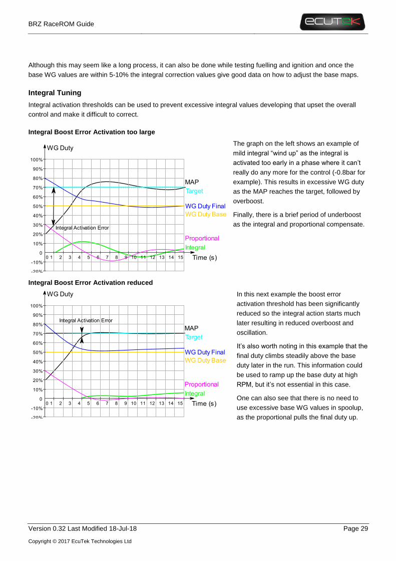
Integral Tuning
Integral activation thresholds can be used to prevent excessive integral values developing that upset the overall
control and make it difficult to correct.
Integral Boost Error Activation too large
The graph on the left shows an example of
mild integral “wind up” as the integral is
activated too early in a phase where it can’t
really do any more for the control (-0.8bar for
example). This results in excessive WG duty
as the MAP reaches the target, followed by
overboost.
Finally, there is a brief period of underboost
as the integral and proportional compensate.
Integral Boost Error Activation reduced
In this next example the boost error
activation threshold has been significantly
reduced so the integral action starts much
later resulting in reduced overboost and
oscillation.
It’s also worth noting in this example that the
final duty climbs steadily above the base
duty later in the run. This information could
be used to ramp up the base duty at high
RPM, but it’s not essential in this case.
One can also see that there is no need to
use excessive base WG values in spoolup,
as the proportional pulls the final duty up.
1 4 1 11 1 1 14 1
%1
%
%
%4
%
%
%
%
%
%1
%1
%
Time s
WG Duty
Integral
WG Duty Final
MAP
Target
Proportional
Integral Activation Error
WG Duty Base
1 4 1 11 1 1 14 1
%1
%
%
%4
%
%
%
%
%
%1
%1
%
Time s
WG Duty
Integral
WG Duty Final
MAP
Target
Proportional
Integral Activation Error
WG Duty Base

BRZ RaceROM Guide
Version 0.32 Last Modified 18-Jul-18 Page 30
Copyright © 2017 EcuTek Technologies Ltd
Closed Loop Fuel Control
Introduction
The factory closed loop fuelling on BRZ is mostly concerned with lean AFR targets (some 2017 roms now have
mostly full time closed loop). To improve the speed of tuning, and massively improve the reliability and safety of
remote tuning, RaceROM now adds the option of full load closed loop fuel correction.
CL AFR Error definition
As there are a variety of ways to define error we should first establish how RaceROM does it. It is not simply the
difference between the AFR target and actual as that will give a different error depending on the current AFR.
Instead we use a ratio error converted into a percentage as below.
𝐴𝐹𝑅 𝐸𝑟𝑟𝑜𝑟 % = 100% × (1 −𝐴𝐹𝑅 𝑇𝑎𝑟𝑔𝑒𝑡
𝐴𝐹𝑅 𝐴𝑐𝑡𝑢𝑎𝑙)
An error of -20%(negative) is 20% too lean, and an error of 20% is 20% too rich.
Live Data Parameters
• AFR Actual – AFR from
• AFR Target – Current AFR target (comes from number of maps and corrections)
• CL AFR Error – Percentage AFR error using (using Wideband sensor if selected in CL options)
• CL AFR Integral Correction – CL Function integral in multiplier of fuel quantity
• CL AFR Proportional Correction – CL Function proportional value in multiplier of fuel quantity
• CL Final Correction – Final percentage correction, positive is increase fuel
• CL Status – Status of the closed loop function to indicate activity and diagnosis
The CL Status parameters are as below, they are added to give a unique number (1+2+4 = 7) for diagnosis. For CL
to be active CL Status needs to be 31 or above, if it is 30 or below, it will be inactive.
1 = RPM over threshold OK (over threshold)
2 = Engine load OK (over threshold)
4 = ECT OK (over threshold)
8 = Runtime OK (over threshold)
16 = Fuelcut OK (not active)

BRZ RaceROM Guide
Version 0.32 Last Modified 18-Jul-18 Page 31
Copyright © 2017 EcuTek Technologies Ltd
Map List
The maps used to initiate and control full load closed loop fueling are below
CL Fuel Final Correction Min/Max
These are the limits on how far the CL fueling system can correct, they are in percentage of AFR target
CL Integral Correction
This is the integral step amount for integral fuel correction, the fuel error values are in % error to target and the
output is in fuel quantity correction amount in % correction amount. They are profiled to prevent integral wind up
with large fuel errors.
CL Integral Correction Min/Max
These are the limits on how far the integral correction in CL fueling system can correct, they are in multiplier of fuel
volume correction (0.2 = 20%)

BRZ RaceROM Guide
Version 0.32 Last Modified 18-Jul-18 Page 32
Copyright © 2017 EcuTek Technologies Ltd
CL Integral Multiplier
This map controls the amount of integral applied at different load and engine speeds, this is to lessen the effect of
integral corrections when the light load AFR is less important and the exhaust gas flow is slower so correction
speeds may be too fast.
CL Fuel Min Engine Load (w/Hysteresis)
The OEM CL fueling may be adequate at lower engine speeds so we have added the ability to switch it on only
when the two load /PRM thresholds are exceeded. The lower value is the hysteresis value it is he amount below
the original value that he parameter must drop below for CL fueling to switch back off.
CL Fuel Min RPM (w/Hysteresis)
The OEM CL fueling may be adequate at lower loads so we have added the ability to switch it on only when the
three load/RPM/ECT thresholds are exceeded. The lower value is the hysteresis value it is he amount below the
original value that he parameter must drop below for CL fueling to switch back off.
CL Fuel Min ECT (w/Hysteresis)
The OEM CL fueling may be adequate at lower loads so we have added the ability to switch it on only when the
three load/RPM/ECT thresholds are exceeded. The lower value is the hysteresis value that must be dropped below
for CL fueling to switch back off.
CL Fuel Min ECT (w/Hysteresis)
So that the car has time to stabilise go through cat warm up or for the O2 sensor to heat up after cold start a run
timer has been added to prevent bad values being given by the sensor.

BRZ RaceROM Guide
Version 0.32 Last Modified 18-Jul-18 Page 33
Copyright © 2017 EcuTek Technologies Ltd
CL Proportional Correction
As with any closed loop system PI system the proportional and integral components are calculated separately and
added together to obtain the final correction value. This map is the proportional component of the calculation and is
applied instantaneously to the fuel volume corrections. The fuel error is in percentage of target AFR and the output
is in fuel volume % correction.
CL Proportional Multiplier
This map controls the amount of proportional correction applied at different load and engine speeds, this is to
lessen the effect of proportional corrections when the light load AFR is less important and the exhaust gas flow is
slower so correction speeds may be too fast.

BRZ RaceROM Guide
Version 0.32 Last Modified 18-Jul-18 Page 34
Copyright © 2017 EcuTek Technologies Ltd
Closed Loop Fuel Control Options
Closed loop fueling can be enabled in individual modes and you can select to use either a wideband sensor
imported through Custom Sensors (Enable Wideband O2 sensor Mode 1-4) or the OEM sensor as a default. If
you select Enabled Closed Loop Fuel Control Calculation Only in Mode 1-4 the value is calculated but not
applied to the final fuel volume calculations. This could be useful to judge the effects before applying a final
correction value allow you to tune the system response to acceptable levels without it making changes.
Currently Race ROM Closed loop fueling can be applied irrespective of whether the OEM function is active, this
can cause the fuel trims to fight each other so be sure to set the RR CL fueling activation thresholds above where
the OEM strategy works.

BRZ RaceROM Guide
Version 0.32 Last Modified 18-Jul-18 Page 35
Copyright © 2017 EcuTek Technologies Ltd
FlexFuel
Introduction
Flex Fuel support was added as an integral part of the version 10 RaceROM upgrade. It uses a strategy of ignition
and AFR target modifier maps for 100% E85 and 2d maps to determine how much of that modification is applied.
The difference in base fuel requirement is taken care by the FlexFuel Quantity Multiplier map and a 2d blend
override map. Typically, 40% extra fuel will be required for 100% E85 to maintain the same Lambda (therefore the
same reported petrol AFR), and the transition will be quite linear. The change in ignition advance will probably
more readily be applied with most, if not all of the additional advance added by 50% E85.
Currently the patch is supplied with typical values used in the FlexFuel Quantity Multiplier map so that any car
with a Flex Fuel sensor added should start and run reasonably well when E85 fuel is added. Remaining correction
maps for ignition and AFR target are blank.
To start using Flex Fuel, simply define an Ethanol Content sensor in FF Sensor Source or set a fixed ethanol
content using FF Ethanol Content Override. The Flex Fuel ignition and fuelling corrections are always active and
rely on the FlexFuel Ethanol Content remaining at 0% to prevent any changes to the normal gasoline.
Live Data Parameters
• FlexFuel Cranking Multiplier – Overall fuel quantity multiplier only used during cranking
• FlexFuel Ethanol Content – Filtered and conditioned Ethanol content % used in all FF calculations
• FlexFuel Ethanol Content - Raw – The output directly from the ethanol content sensor
• FlexFuel Ignition Advance – Additional ignition advance after all FF compensations
• FlexFuel Quantity Multiplier – Current fuel multiplier based on ethanol content and engine temp
• FlexFuel AFR Adjustment – Offset to normal target AFR by FlexFuel Strategy
Map List

BRZ RaceROM Guide
Version 0.32 Last Modified 18-Jul-18 Page 36
Copyright © 2017 EcuTek Technologies Ltd
FF Ethanol Content Override
It is not always practical to add a Flex Fuel sensor to every car that uses alcohol in the fuel, and many users may
wish to pre-mix a specific amount of ethanol, methanol or E85 with their regular gasoline to improve performance.
Pre-mixed ratios of alcohol can now be catered for in the RaceROM Flex Fuel strategy by entering the ethanol
content in this map.
A default value of -1 is employed to use the ethanol content from the sensor.
FF Ethanol Content Hold Engine Load
When obtaining the ethanol content from a sensor in the fuel line, it’s not unusually to have fluctuating sensor
readings due to aeration of the fuel. To mitigate the effects of this phenomenon the ethanol content employed by
the Flex Fuel strategy can be temporarily locked at high load.
If the load exceeds this threshold and if the RPM exceeds FF Ethanol Content Hold RPM, the FlexFuel Ethanol
Content will be fixed until either of the two thresholds are no longer met.
FF Ethanol Content Hold RPM
In conjunction with FF Ethanol Content Hold Engine Load this can be used to lock the ethanol content when fuel
flow is maximised.
FF Quantity Multiplier
This dictates the additional fuel based on Ethanol content (0-100%) and coolant temperature. It would not be
unusual to need to add additional E85 when cold due to some unburnt fuel going through the engine. Pure Ethanol
typically requires 40% more fuel to maintain the same lambda (or apparent AFR) as gasoline, there is no significant
change to injector flowrates when using E85.
If you want to run a richer or leaner AFR when using E85 do not try and compensate with this map as the ECU will
use fuel corrections to hit the same target AFR target, instead use FF Target AFR Addition Max.

BRZ RaceROM Guide
Version 0.32 Last Modified 18-Jul-18 Page 37
Copyright © 2017 EcuTek Technologies Ltd
FF Cranking Multiplier
The fuel quantity at cranking will be affected by the FlexFuel Quantity Multiplier map however it may be required
to change the fuelling further at low temperatures when cranking. This map is a 0-2 scalar and will multiply the
base fuelling only when cranking.
FF Cranking Multiplier Decay Rate
A FF Cranking Multiplier Decay Rate in reduction of multiplier value amount per second is also used and can be
adjusted if required.
FF Cranking RPM Threshold
The additional fuel added during cranking by FF Cranking Multiplier will start decaying when the RPM exceeds
this threshold.
FF Target AFR Addition Max
This map has units of AFR and a positive number will add to the preceding target AFR resulting in a leaner final
AFR. Blank by default, the pictured table uses +0.5 at high load to lean out the AFR from (for example) 11:1 at very
high load on pump fuel to a cleaner and crisper 11.5:1. However if the base map is already using a good fuel or
even a race fuel that would typically run closer to 12.2:1 then it would be entirely possible to want to lower the
target AFR when using high levels of E85.
The final AFR target is the result of this map weighted by the result of FF Target AFR Addition Blend.

BRZ RaceROM Guide
Version 0.32 Last Modified 18-Jul-18 Page 38
Copyright © 2017 EcuTek Technologies Ltd
FF Target AFR Addition Blend
This map dictates how much of the AFR change is used for a given Ethanol content. The resulting AFR Target is
defined as
𝐹𝑖𝑛𝑎𝑙 𝐴𝐹𝑅 𝑇𝑎𝑟𝑔𝑒𝑡 = 𝐴𝐹𝑅 𝑇𝑎𝑟𝑔𝑒𝑡 + (𝐹𝐹 𝑇𝑎𝑟𝑔𝑒𝑡 𝐴𝐹𝑅 𝐵𝑙𝑒𝑛𝑑 × 𝐹𝐹 𝑇𝑎𝑟𝑔𝑒𝑡 𝐴𝐹𝑅 𝐴𝑑𝑑𝑖𝑡𝑖𝑜𝑛 𝑀𝑎𝑥)
FF Ignition Timing Max Addition
Default values used are for demonstration only they do not give optimum performance but are considered safe.
This represents the absolute maximum ignition advance that can be added, typically at 100% E85 but it can be
added at lower concentrations using the FlexFuel Ignition Timing Addition Blend map. The values in the table
below are not tested but purely representative. They would result in significant torque gains and would not
necessarily be suitable on a stock engine.
We have chosen to use an addition map as it would require 4 ignition maps, one for each MapSwitch mode to have
totally independent maps. An adder map is easier to comprehend for most tuners but should you wish to use total
advance maps, it can of course be done using Custom Maps.

BRZ RaceROM Guide
Version 0.32 Last Modified 18-Jul-18 Page 39
Copyright © 2017 EcuTek Technologies Ltd
FF Ignition Timing Addition Blend
The values are a multiplier of the FF Ignition Timing Max Addition values and dictate how much of that advance
is added for a given Ethanol content. The resulting ignition advance is calculated as
𝐹𝑖𝑛𝑎𝑙 𝐼𝑔𝑛𝑖𝑡𝑖𝑜𝑛 𝑇𝑖𝑚𝑒 = 𝐼𝑔𝑛𝑖𝑡𝑖𝑜𝑛 𝑇𝑖𝑚𝑖𝑛𝑔 + (𝐹𝐹 𝐼𝑔𝑛𝑖𝑡𝑖𝑜𝑛 𝐵𝑙𝑒𝑛𝑑 × 𝐹𝐹 𝐼𝑔𝑛𝑖𝑡𝑖𝑜𝑛 𝑀𝑎𝑥 𝐴𝑑𝑑𝑖𝑡𝑖𝑜𝑛)
Getting Started with Flex Fuel
Overview
Flex Fuel set up and tuning broadly follows the following method.
• Configure a sensor (or set a fixed ethanol content override)
• Change fuel
• Correct fuelling
• Tune ignition advance and target AFR
• Optimise boost targets
• Recheck at lower ethanol content levels (optional depending on experience and application)
Sensor Kits
A variety of sensor kits are available in PnP form.
https://www.delicioustuning.com/flexfuel
https://www.viscontituning.com/products/brz-frs-gt86-flex-fuel-kit
http://www.moto-east.com/store/moto-east-flex-fuel-ft86.html
http://fullblownmotorsports.com/full-blown-frs-brz-gt86-flex-fuel-kit
Tuning
The key to a successful Flex Fuel tune, is to start with a well-polished gasoline tune! You absolutely cannot tune for
ethanol if there are unknowns surrounding key elements like injector scaling, MAF scaling or your VE map. It’s
normal to go from tuning at 0% ethanol straight to your maximum to get the best accuracy at high ethanol content.
Like conventional tuning, tuning for ethanol can be an iterative process, and it is good process to revisit AFR and
boost levels after some quality ignition timing optimisation.

BRZ RaceROM Guide
Version 0.32 Last Modified 18-Jul-18 Page 40
Copyright © 2017 EcuTek Technologies Ltd
Fuelling
If fuelling on gasoline is correct (the fuelling is on target +/- 3%), start with the default FF Quantity Multiplier map
and make fine adjustments to maintain the same AFR on ethanol as was achieved on gasoline. To change the
AFR target when transitioning to ethanol, use the FF Target AFR Addition Max map to set a maximum offset from
the main fuel map. The best AFR for ethanol is application dependant, if the gasoline map is very rich (<11 AFR)
then it’s normal to make it leaner on ethanol. If MBT Ignition is achieved on an N/A engine then it may be
advantageous to run closer to 12.5:1 AFR, but dyno testing is the best way to find out.
Be aware of changing fuel flow requirements, and that you may need to increase Port Injection ratio to
accommodate this extra fuel flow predominantly through the port injectors.
Starting
Make sure that the car has been tuned appropriately on gasoline, especially when using large injectors which
require cranking maps to be altered.
It may be useful to use the FF Cranking Multiplier to change the amount of fuel employed at startup, but most
applications will be fine with the default settings.
Ignition Timing
Ethanol tuning is best achieved when the main ignition maps are tuned to the knock limit, and the car runs happily
with and advance multiplier of 1 so max timing is achieved. To increase power, add ignition timing via FF Ignition
Timing Max Addition map until you begin to reach the limits of knock or that power no longer increases.
If tuning an N/A engine with high ethanol content it’s likely that MBT will be achievable, therefor a dyno will
probably be required to find the available power.
If tuning a forced induction engine, it’s more likely that ignition will be knock limited at the highest boost levels,
more so at peak torque than at peak power. Again, a dyno is preferable to get a feel for the way a given car
responds to ethanol tuning.
The default map has conservative numbers to demonstrate the type of trends a tuner might expect.
Boost Control
Remember to set appropriate boost targets and limits when running on ethanol. To maintain a sensible torque
level, it’s not unusual to target less boost at low/mid RPM where torque is maximal, and increase the boost at
higher RPM where the engine is highly knock limited on gasoline.

BRZ RaceROM Guide
Version 0.32 Last Modified 18-Jul-18 Page 41
Copyright © 2017 EcuTek Technologies Ltd
Sensors
Introduction
Custom sensor inputs have been added for fuel pressure and coolant pressure, and extra functionality has been
added to the existing Flex Fuel sensor input, which now falls under the Sensor Scaling category with all the OEM
and RaceROM sensors.
Live Data Parameters
• Coolant Pressure – Coolant pressure (gauge) in bar
• FlexFuel Ethanol Sensor Output – Ethanol content as reported by the sensor output, including filtering
• Fuel Pressure-PI – Low pressure/port injector line pressure (gauge)
• Gear Shift Sensor – A simple 0 or 1 status. 0 represents not active, and 1 is active.
• AFR - Wideband – the AFR output from the wideband sensor as per the sensor scaling.
Map List

BRZ RaceROM Guide
Version 0.32 Last Modified 18-Jul-18 Page 42
Copyright © 2017 EcuTek Technologies Ltd
Coolant Pressure
CP Sensor Source
Select the sensor source to input the voltage to. If “No Sensor” is selected, sensor live data will report the default
value CP Sensor Default.
CP Sensor Scaling
CP Sensor Smoothing
Smoothing is achieved thus:
𝑁𝑒𝑤 𝑆𝑚𝑜𝑜𝑡ℎ𝑒𝑑 𝑉𝑎𝑙𝑢𝑒 = 𝑁𝑒𝑤 𝑉𝑎𝑙𝑢𝑒 × 𝑆𝑚𝑜𝑜𝑡ℎ𝑖𝑛𝑔 + 𝑂𝑙𝑑 𝑆𝑚𝑜𝑜𝑡ℎ𝑒𝑑 𝑉𝑎𝑙𝑢𝑒 × (1 − 𝑆𝑚𝑜𝑜𝑡ℎ𝑖𝑛𝑔)
The default of 1.0 results of no
smoothing, and a very low value of
0.01 will result in heavily smoothed
values.
The graph on the left shows the
various responses to a step input
depending on the smoothing value
used.
0.0
1.0
2.0
3.0
4.0
5.0
6.0
0.000 0.200 0.400 0.600 0.800 1.000
Smoothing Effect
Input 0.1 0.25 0.5 0.75

BRZ RaceROM Guide
Version 0.32 Last Modified 18-Jul-18 Page 43
Copyright © 2017 EcuTek Technologies Ltd
CP Sensor Min & CP Sensor Max
Used to define the normal voltage range of the sensor. If the voltage falls outside of this range it is considered to
have failed and will report the default value.
CP Sensor Default
The value reported by the sensor if no output is defined or if the sensor voltage falls outside of the range defined by
the min and max.
FlexFuel Ethanol Content
FF Sensor Source
Choose the ECU 0-5v input to use for the Flex Fuel sensor.
FF Sensor Scaling
This map sets the sensor scaling using a 0-5v input defined by Flex Fuel Sensor Source that many aftermarket
Flex Fuel gauges or sensor interfaces use. The map is shown with its default values and many setups will not
require anything different but you can fine tune to match the RaceROM Ethanol content to that of a gauge.
FF Sensor Smoothing
Smoothing is achieved thus:
𝑁𝑒𝑤 𝑆𝑚𝑜𝑜𝑡ℎ𝑒𝑑 𝑉𝑎𝑙𝑢𝑒 = 𝑁𝑒𝑤 𝑉𝑎𝑙𝑢𝑒 × 𝑆𝑚𝑜𝑜𝑡ℎ𝑖𝑛𝑔 + 𝑂𝑙𝑑 𝑆𝑚𝑜𝑜𝑡ℎ𝑒𝑑 𝑉𝑎𝑙𝑢𝑒 × (1 − 𝑆𝑚𝑜𝑜𝑡ℎ𝑖𝑛𝑔)
The default of 1.0 results of no smoothing, and a very low value of 0.01 will result in heavily smoothed values.
FF Sensor Min & FF Sensor Max

BRZ RaceROM Guide
Version 0.32 Last Modified 18-Jul-18 Page 44
Copyright © 2017 EcuTek Technologies Ltd
Used to define the normal voltage range of the sensor. If the voltage falls outside of this range it is considered to
have failed and will report the default value. Aftermarket Flex Fuel sensors that output 0-5v outputs however,
normally use a full 0-5v range so the limits for a Flex Fuel sensor should be set appropriately for example a
minimum of -1v and a maximum of 5.1 volts.
FF Sensor Default
The value reported by the sensor if no output is defined or if the sensor voltage falls outside of the range defined by
the min and max.
Fuel Pressure
FP Sensor Source
Select the sensor source to input the voltage to. Currently the boost sensors are not an option, although this is
currently being looked at. If “No Sensor” is selected, sensor live data should just report .
FP Sensor Scaling
Sensor output based on input voltage.
FP Sensor Smoothing
Smoothing is achieved thus:
𝑁𝑒𝑤 𝑆𝑚𝑜𝑜𝑡ℎ𝑒𝑑 𝑉𝑎𝑙𝑢𝑒 = 𝑁𝑒𝑤 𝑉𝑎𝑙𝑢𝑒 × 𝑆𝑚𝑜𝑜𝑡ℎ𝑖𝑛𝑔 + 𝑂𝑙𝑑 𝑆𝑚𝑜𝑜𝑡ℎ𝑒𝑑 𝑉𝑎𝑙𝑢𝑒 × (1 − 𝑆𝑚𝑜𝑜𝑡ℎ𝑖𝑛𝑔)
The default of 1.0 results of no smoothing, and a very low value of 0.01 will result in heavily smoothed values.
FP Sensor Min & FP Sensor Max
Minimum nominal voltage expected from the sensor, below which a fault will be assumed and the FP Sensor
Default value returned. This can be set to a negative value such as -1 to never trigger a failure.
BRZ RaceROM Guide
Version 0.32 Last Modified 18-Jul-18 Page 45
Copyright © 2017 EcuTek Technologies Ltd
Maximum nominal voltage expected from the sensor, over which a fault will be assumed and the FP Sensor
Default value returned. This can be set to a high value such as 6 to never trigger a failure.
FP Sensor Default
If the sensor voltage is below FP Sensor Min or above FP Sensor Max, the sensor will be considered to have
failed and the default value will be returned. Typically, sensors will give a useful output over a range a little less
than their full-scale output so that faults can be diagnosed. For example, many pressure sensors will output
between 0.5 and 4.5 volts, and voltages significantly outside this range would indicate an error.
Gear Shift Sensor
With more BRZ being used in racing applications a higher number of sequential boxes are being employed. To
allow for proper WOT shifts a gear shift sensor has been added to custom maps this will allow the output of the
gearstick shifter command to be inputted into the ECU and used to make torque reductions. The best results will be
found with a proper closed loop controller output like the Geartronics units
http://www.geartronics.co.uk/flatshift.htm
Any other closed loop control or 0-5V conditioned strain gauge output could be used though.
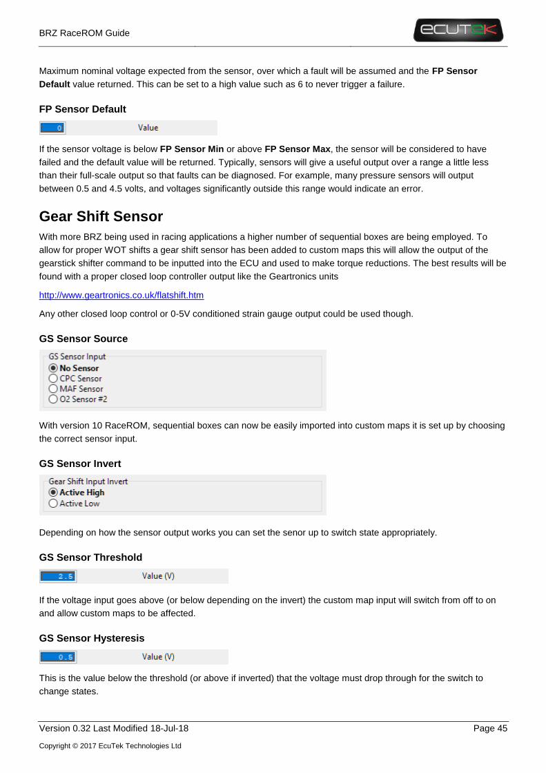
GS Sensor Source
With version 10 RaceROM, sequential boxes can now be easily imported into custom maps it is set up by choosing
the correct sensor input.
GS Sensor Invert
Depending on how the sensor output works you can set the senor up to switch state appropriately.
GS Sensor Threshold
If the voltage input goes above (or below depending on the invert) the custom map input will switch from off to on
and allow custom maps to be affected.
GS Sensor Hysteresis
This is the value below the threshold (or above if inverted) that the voltage must drop through for the switch to
change states.

BRZ RaceROM Guide
Version 0.32 Last Modified 18-Jul-18 Page 46
Copyright © 2017 EcuTek Technologies Ltd
Wideband O2 Sensor
Due to the risks and complexity of using a wideband sensor to do closed loop fuel control on full load extra
precautions have been made to account for the many different failure modes an oxygen sensor can see. There are
minimum and maximum sensor voltages stuck voltage and the sensor smoothing functions added as well as
debugging parameters to assist in setting the system up.
WB Sensor Source
To set up the sensor foe use in closed loop fueling or logging simply enable the correct input option. Keep in mind
that DTC’s may also need to be disabled to enable correct operation of the vehicle.
WB Sensor Smoothing
There are also smoothing factors, where 1= no smoothing and 0 = complete smoothing and the value will never
change.
WB Sensor Min & WB Sensor Max
The sensor minimum and maximum voltages can be set up to allow open and short circuit protection.
WB Sensor Default
The default sensor value is the value used when a failure mode is detected it is set at 14.7 but can be adjusted if
that is what is desired.
WB Sensor Stuck Value
Some external wideband sensors will output a fixed voltage in an error condition. This voltage should be set to
match the voltage output by the wideband device in an error condition. If you’re using an external WB temporarily
for tuning only, then this should be set to a value that the ECU will not see (6v for example) to prevent the sensor
being ignored.
WB Sensor Stuck Timer
Time in seconds that the voltage must remain at WB Sensor Stuck Value before the ECU considers there to be a
problem with the ECU.
BRZ RaceROM Guide
Version 0.32 Last Modified 18-Jul-18 Page 47
Copyright © 2017 EcuTek Technologies Ltd
Speed Density
There have been some changes made at the request of tuners to help improve the tunability of the RaceROM
speed density. These changes include the following maps
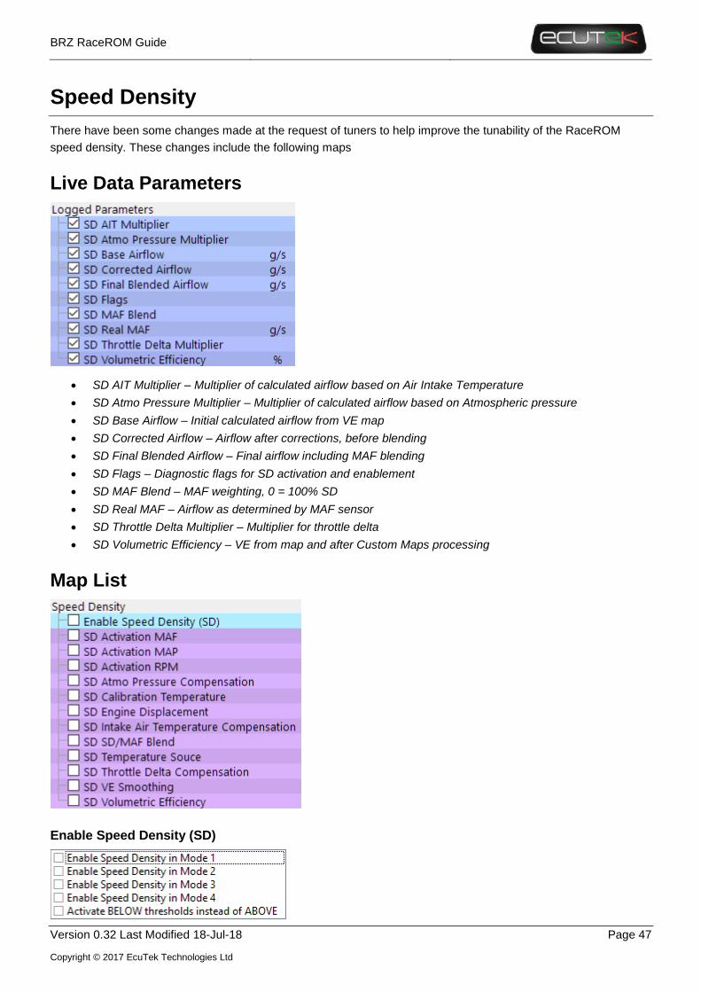
Live Data Parameters
• SD AIT Multiplier – Multiplier of calculated airflow based on Air Intake Temperature
• SD Atmo Pressure Multiplier – Multiplier of calculated airflow based on Atmospheric pressure
• SD Base Airflow – Initial calculated airflow from VE map
• SD Corrected Airflow – Airflow after corrections, before blending
• SD Final Blended Airflow – Final airflow including MAF blending
• SD Flags – Diagnostic flags for SD activation and enablement
• SD MAF Blend – MAF weighting, 0 = 100% SD
• SD Real MAF – Airflow as determined by MAF sensor
• SD Throttle Delta Multiplier – Multiplier for throttle delta
• SD Volumetric Efficiency – VE from map and after Custom Maps processing
Map List
Enable Speed Density (SD)

BRZ RaceROM Guide
Version 0.32 Last Modified 18-Jul-18 Page 48
Copyright © 2017 EcuTek Technologies Ltd
Speed density can be enabled on a per Mapswitch Mode basis. When SD is enabled all three threshold conditions
need to be met for SD to become active, once active the calculated airflow is still affected by the SD SD/MAF
Blend map.
If the Active BELOW thresholds instead of ABOVE option is also selected all the thresholds are reversed, but
the higher values should still be in the top cell of each map.
SD Activation MAF
The minimum MAF condition is met when the MAF as measured by the sensor exceeds the top value, and remains
until the measured MAF drops below the bottom value. In the above example, assuming the RPM and MAP
conditions were met, SD would become active when the MAF increased above 100g/s and remain active until the
MAF dropped below 50g/s.
SD Activation MAP
The minimum MAP condition is met when the MAP exceeds the top value, and remains until the MAP drops below
the bottom value. In the above example, assuming the RPM and MAF conditions were met, SD would become
active when the MAP increased above 1.2bar and remain active until the MAP dropped below 0.9bar. Full time SD
requires both to be 0 and this is the default.
SD Activation RPM
The minimum RPM condition is met when the RPM exceeds the top value, and remains until the RPM drops below
the bottom value. In the above example, assuming the MAP and MAF conditions were met, SD would become
active when the MAP increased above 2000rpm and remain active until the RPM dropped below 1800rpm. Full
time SD requires both to be 0 and this is the default.
SD Atmo Pressure Compensation
While atmospheric pressure has been accommodated for in the Speed density equations for mass airflow
conversions further compensations can be made using this map. It multiplies the VE values based on atmospheric
pressure and manifold pressure.
SD Calibration Temperature

BRZ RaceROM Guide
Version 0.32 Last Modified 18-Jul-18 Page 49
Copyright © 2017 EcuTek Technologies Ltd
If the SD Temperature Source is set to “Use fixed charge temp and IAT compensation” this is the assumed charge
temperature fed into the ideal gas law calculation used for speed density.
SD Intake Air Temperature Compensation
This is a further correction to the calculated airflow based on Intake Air Temperature and can be used to make a
custom correction to airflow. Typically, this is used if SD Temperature Source is set to “Use fixed charge temp and
IAT compensation”, but should be set to 100 if SD Temperature Source is set to “Use MAF Sensor internal IAT
sensor”.
SD SD/MAF Blend
To improve the transition between MAF and Map for those using hybrid SD a new map for blending between the
MAF and SD generated airflows has been added. Simple set this to use set what percentage of MAF or Airflow is
used in the airflow calculation. 1= full time MAF, 0 = Full time SD.
This map can be used to good effect to use SD only where it’s really needed with more flexibility than the original
on/off thresholds offered. For example, on a car with a roots style supercharger, MAF can be employed at both low
RPM when MAP signals are not very smooth, and high RPM where MAP may exceed the reading limits of the
stock sensor. Using smooth transitions will eliminate sudden changes in calculated airflow and the resulting
fuelling.
SD Temperature Source

BRZ RaceROM Guide
Version 0.32 Last Modified 18-Jul-18 Page 50
Copyright © 2017 EcuTek Technologies Ltd
This option selects the source of the temperature value fed into the ideal gas law calculation that’s used to
generate the mass airflow.
SD Throttle Delta Compensation
Used to correct airflow changes resulting from throttle transients using a simple percentage compensation based
on throttle delta (difference in throttle angle per measurement cycle). On forced induction cars, changes in airflow
at positive manifold pressure are much subtler, so the values in this map may need to be significantly reduced
especially at higher RPM.
SD VE Smoothing
Lowering this value will smooth the initial VE value as it’s looked up from the SD VE map.
SD Volumetric Efficiency
The core of speed density tuning is the Volumetric Efficiency map. VE is the ratio of the actual volume of air
retained in the cylinder to the swept volume (capacity) of the cylinder. The default values in the map were
calibrated on a stock car and allow SD to be enabled and have a car that should run well enough for fine tuning for
your own hardware.

BRZ RaceROM Guide
Version 0.32 Last Modified 18-Jul-18 Page 51
Copyright © 2017 EcuTek Technologies Ltd
Large changes in the VE map should not be used to correct for fuel system deficiencies. If a car being tuned
requires values beyond about 110% it suggests there is a fuel flow or injector calibration issue.

BRZ RaceROM Guide
Version 0.32 Last Modified 18-Jul-18 Page 52
Copyright © 2017 EcuTek Technologies Ltd
5. Custom Maps
Introduction
We have improved our unique and innovative Custom Maps feature to enable even more tuning possibilities. With
the addition of our dedicated boost control and Flex Fuel strategies, all 16 custom maps are now available for the
tuners to further exploit the power of RaceROM.
Additional inputs and outputs, combined with expanded possibilities for manipulating the values, allow for complex
control strategies to be created from something as simple as a fuel pressure fail safe to a slip target based multi-
layered traction control system.
Inputs
Version 10 for BRZ brings a selection of new inputs for custom maps, highlighted below.
AFR – Actual (n:1)
Is the measured AFR from the OEM O2 sensor.
AFR – Target (n:1)
Is the target AFR used for all fueling target setpoint including CL fueling
AFR – Wideband (n:1)
This value is from the Custom Sensors set up as a wideband and is measure in AFR points directly as it is scaled
from the wideband sensor input. It could be used to set up correction or failsafe’s if required.

BRZ RaceROM Guide
Version 0.32 Last Modified 18-Jul-18 Page 53
Copyright © 2017 EcuTek Technologies Ltd
Boost Target (Bar)
This value is the boost target output of RaceROM Boost control functions. It is only active if the Boost control
system is enabled and can be used to make corrections to the target as desired before it goes into the WG duty
maps.
Clutch Pedal
This value is a digital parameter representing the clutch pedal position, this could be used if you are using a
sequential gearbox and corrections for shifting are required. The clutch switch input of 1 = clutch switch active
which is when the clutch pedal is down, 0 = clutch switch de-active which is when the clutch pedal is up.
Coolant Pressure (bar)
This value is from the custom sensor input and is in bar it can be used to make failsafe correction in custom maps
Fuel Pressure (Bar)
This value is from the custom sensor input and is in bar it can be used to make failsafe correction in custom maps
Ethanol Content (%)
From the FlexFuel strategy this is a dedicated live data parameter that can be used as an input to Custom Maps to
extend the base FlexFuel features.
Gear Shift Sensor
From the Custom Sensors settings to be used for shift cuts and retards on sequential gearboxes.
Ignition Timing Final (º)
The actual final ignition timing after all compensations or torque corrections. WARNING This input should not be
combined with an output using ignition timing as it will produce unpredictable results. It can however be used to act
upon extremes of ignition timing such as those seen during gear change, launch control and other torque
reductions.
Injector open Time DI (ms)
This value is the actual open time of the Direct Injectors after corrections. It can be used to trigger safeguards or
compensations based on the activity of the injectors.
Injector open Time PI (ms)
This value is the actual open time of the Port Injectors after corrections. It can be used to trigger safeguards or
compensations based on the activity of the injectors.
Knock Correction (º)
custom maps input uses "knock correction"+ "fine correction" so will always reflect fine correction even on WOT, it
will also add in the short terms correction you may see on lighter loads.
Lateral G (g)
This value is from G sensor in the Body control module, this could be used to modify a slip based traction control
custom map setup.
Launch RPM (RPM)
This value is the set launch control RPM it can be used to make compensations and corrections when trying to
manage boost during the LC process
Launch RPM Error (RPM)
The Launch RPM error defined as RPM – Launch RPM Target. This can be used to make further corrections to the
engine running based on disparity between the actual and target RPM. For example, compensations and
corrections to manage boost during the LC process.
VVT Exhaust Angle(º)
This value is the actual current exhaust cam angle this can be used as an input for CAM off CEL warning maps or
to make VVT error adjustments for cam angle against a VVT target map.
VVT Intake Angle(º)
This value is the actual current intake cam angle this can be used as an input for CAM off CEL warning maps or to
make VVT error adjustments for cam angle against a VVT target map.

BRZ RaceROM Guide
Version 0.32 Last Modified 18-Jul-18 Page 54
Copyright © 2017 EcuTek Technologies Ltd
VVT Intake Error (º)
This value is the error value between the target map and actual VVT position. It can be used for failsafe’s in custom
maps etc.
Wheel Slip (%)
Calculated as 100*(Rear WS – Front WS)/Front WS and can be used for traction control strategies. This value is
similar to the slip or spin values found in aftermarket ECUs.
Input Options
• Interpolate between cells
o This is the normal mode of action and it interpolates to the vale between the cells in a linear
fashion
• Select Nearest cells
o Will chose the cells that is closest to the actual value giving a binary switch point (on/off)
• Select Lower Cells
o Will choose the lower axis value closest to the actual value
• Select Higher Cells
o Will choose the higher axis value closes to the actual value
Outputs
Three new outputs have been added in version 10:
Boost Target
This is a new feature that will allow you to adjust the closed loop boost target using a custom map. It will only work
when RaceROM Boost control is active.

BRZ RaceROM Guide
Version 0.32 Last Modified 18-Jul-18 Page 55
Copyright © 2017 EcuTek Technologies Ltd
Torque Actual (Nm)
This can be used to manipulate actual Torque output to other modules like the TCM or VDC.
SD Volumetric Efficiency (%)
Applied over the output of the SD Volumetric Efficiency (VE) map, this can be used for closed loop VE correction,
to compensate for VVT on or off, cam angle error, TPS compensation (e.g. for individual throttle tuning) and for
making temporary corrections to the VE using the RaceROM boost controller or external 0-5v input.
Deactivation Delay
Activation and deactivation now how independent delay times. This means you can trigger a custom map to be
active immediately and it will remain on for a time even if the activation conditions are no longer met, for example a
10 second boost target increase.
Integral Min/Initial/Max
On our previous Custom Maps implementation, the integral function would always start and default back to zero
making multiplication via an integral impossible. An initial value of 1 will fix the issue.

BRZ RaceROM Guide
Version 0.32 Last Modified 18-Jul-18 Page 56
Copyright © 2017 EcuTek Technologies Ltd
6. RaceROM Logging
Logging Speed Improvements
The default OEM method of retrieving live data uses groups of similar or related parameters commonly used for
diagnosing specific problems, a typical usage of a technician using a factory diagnostic tool. This methodology
doesn’t fit very well with the requirements of a tuner, who is more concerned with looking at and recording a wide
range of parameters.
As such when using the OEM live data method for tuning, the ECU typically returns 4-5x more data than a tuner
really needs and logging speeds have previously been slow as a result. From RaceROM v10 onwards we have
improved this by defining groups of live data parameters specifically for tuning, and selectively choosing datatype
and precision to get the best overall compromise of logging speed and data choice.
This snippet shows the OEM and RaceROM
parameters in the live data list. If both the OEM and
RaceROM version of a live data parameter are
default, ProECU will automatically use only the
RaceROM version.
Note this feature only works when a ROM is opened,
so when adding a RaceROM feature file, it’s good
practice to save and re-open the ROM file.
Removing parameters to increase logging speed
The default RaceROM parameter selection is optimised and already in groups. Removing a single parameter will
NOT increase logging speed unless all the parameters in a group are also removed. Therefore, if you want the
best logging speed, the advice is to use the default list, and be very selective about what parameters you add, for
example, adding just Custom Map A Result will also cause the ECU to send live data for Custom Maps B to H
including the interim values.

BRZ RaceROM Guide
Version 0.32 Last Modified 18-Jul-18 Page 57
Copyright © 2017 EcuTek Technologies Ltd
7. What’s not supported
Old Model ROMs
There have been many ECM releases from the factory to fix different issues encountered by the dealer technicians,
this includes the DTC code fixes and the transient ignition retard to protect the DI injector seals (see the manual for
information). RaceROM version 1 does not support the oldest unsuitable CAL ID’s e.g. ZA1J G etc as they
should be upgraded if they are encountered to prevent issues when running and make use of the factory updates.