submitted in fulfilment of part of the requirements for the
TRANSCRIPT


Submitted in fulfilment of part of the requirements for the degree of Magister of Architecture (Professional) in the Faculty of Engineering, the Built Environment and Information Technology.
University of Pretoria, South Africa.

Chapter 1: Introduction ………………………………………………………………………… 6 1.1 Preamble 8 1.2 Multi-Brew 8 1.3 Statement of intent 9
Chapter 2: Macro Context …………………………………………………………………...... 10 2.1 Beer 12 2.1.1 Science behind brewing 14 2.1.2 Brewing process 16 2.1.3 Polemics 17 2.2 Industrial developments 18 2.2.1 Polemics 18 2.3 Pretoria 20 2.3.1 Polemics 20 Chapter 3: Micro Context ……………………………………………………………………... 22 3.1 Scale 24 3.2 Urban analysis 26 3.2.1 Roads 28 3.2.2 Arcades 29 3.2.3 Tram line 29 3.2.4 Mandela development corridor 30 3.3 Site analysis 32 3.3.1 Polemics 35 3.4 Surrounding analysis 38 3.4.1 Transport 38 3.4.2 Public spaces 39 3.4.3 Movement 40 3.4.4 Surrounding uses 41 3.5 Buildings on site 42
Chapter 4: Presedent Study ........................................................................................... 50 4.1 Herzog & de Meuron – Dominus Winery (California) 52 4.1.1 Introduction 53 4.1.2 Considerations 53 4.2 Zaha Hadid – BMW Central Building (Leipzig) 54 4.2.1 Introduction 55 4.2.2 Considerations 55 4.3 Gabriel Fagan – SAB Visitors Centre (Newlands) 56 4.3.1 Introduction 57 4.3.2 Considerations 57
Chapter 5: Design Investigation……………………………………………………………… 58 5.1 Accommodation schedule 60 5.2 Function relationship 65 5.3 City block development 66 5.3.1 Buildings on site 66 5.3.2 Movement after demolition 67 5.3.3 Focus points 68 5.3.4 Walking path and service entrance 69 5.3.5 Building types 70 5.4 Process as generator of shape 71 5.5 Design development 72
Chapter 6: Technical investigation .................................................................................. 84 6.1 Columns and beams 86 6.1.1 Steel 86 6.1.2 Concrete 88 6.2 Floor slabs 89 6.3 Roof construction 90 6.4 Service cores 92 6.5 Ventilation system 92 6.6 Floor plans 94 6.6.1 Ground floor plan 94 6.6.2 First floor plan 96 6.6.3 Second floor plan 98 6.7 Sections 100 6.7.1 Section A-A 100 6.7.2 Section B-B 102 6.8 Elevations 104 6.8.1 North elevation 104 6.8.2 South elevation 106 6.8.3 East elevation 108 6.8.4 West elevation 110 6.9 Details 112
Bibliography ..................................................................................................................... 114
List of Figures ................................................................................................................... 116

Fig. 1: 3D rendering of brewery chimney

1.1 – Preamble
This dissertation investigates an alternative approach towards light industrial development in an attempt to eliminate those characteristics which could be considered as negatives for either the users or the urban conditions resulting from it. The conventional approach to industrial development whereby industries are located in specific precincts usually isolated from residential and commercial locations is challenged.
1.2 – Multi-Brew
Multi-brew is a beer brewing facility consisting of multiple parts. The major focus will be a micro brewery, alternatively defined as a small craft brewery that seeks unique quality in beer. The brewery will be such that several brewers will be able to use the facilities with multiple production lines. The beer produced at the brewery will not be of any one or pre-decided type and will encourage the freedom of creativity of all the brewers. They will be able to hire one of several production lines and be supplied with the communal facilities to brew their beer. The brewery will further include research and marketing facilities for the users.
In addition, in an attempt to expand the facilities nationally, there will be a brewing school at which students can learn the art and science of brewing beer. The school will consist of classrooms and research facilities similar to those of the actual brewery. It will also have facilities to educate the public in a diverse spectrum of beer and beer brewing.
A restaurant and brew pub will be included. These will sell the beer produced in the brewery and also in the school. A large variety of beers will be sold. The types will differ depending on the specific times of unique production. The restaurant will open towards a shared public space with a covered activity platform used predominantly as a market.
The brewery will form part of a public green strip that runs around the edge of the Pretoria Central Business District (CBD).
1.3 – Statement of intent
The brewery investigates the possibility of a light industry in an urban context. It is aimed at informing the public about how it functions and its operational processes through its architecture. Problems such as visual comfort and public acceptance arising from this type of controversial integration must be addressed. The architecture applied to this new industry should be in character with its surrounding urban fabric.
This integration also offers the opportunity for public education through architectural language. The operations of an industry can be demonstrated to the public by architecture that physically separates functions while retaining visual connections. The task of integrating the visual connections with those functions required in an urban environment will be explored and appropriately applied.
Fig. 2: Concept sketch May 2007
8 9

Fig. 3: 3D rendering of an area in Pretoria CBD

Beer is one of the oldest alcoholic beverages in the world. Records date back to the 6th millennia BC in ancient Egypt and Mesopotamia (Fig. 4). From the earliest times, beer was produced and sold on a domestic scale. However, after the industrial revolution most domestic production ceased and industrial production took over. Advances in technology such as the creation of hydrometers and thermometers allowed greater control and better understanding of the process, changing brewing for all time to come (http://en.wikipedia.org/wiki/Beer).
South Africa is no exception to this rich history and in 1658, a mere six years after Jan van Riebeeck landed on the southern tip of Africa, the first European-type beer brewed from South African barley was exported to Batavia and Holland. The story of brewing in South Africa as an industrial activity is largely that of three companies: Ohlsson’s Cape Breweries Limited (established 1882), Chandler’s Brewery (established 1884), and the South African Breweries Limited (established 1889) (PRETORIA 1962:271). Major milestones include the merger between the three dominant brewing companies in 1956 to become the South African Breweries Limited (SAB), and the recent merger between SAB and Miller Brewing to become SAB Miller, recognised today as one of the largest brewing companies globally.
Another significant (yet often overlooked) influence on the history of South African beer production and culture is one of indigenous knowledge (Fig. 5). Many local breweries, operated mostly by black communities, brewed forms of sorghum and maize beers long before any European settlements and many continue to operate today.
Fig. 4: Ancient Egyptian painting showing people drinking beer.
Fig. 5: Photo of people selling locally brewed beer.
1312

2.1.1 – Science behind brewing
In most cases the brewing process is similar for most breweries. The differences depend on factors such as the specific type of beer being brewed, the size of the brewery, and nature of the brewery operations.
When designing a brewery that allows different types of beers to be produced over different periods of time and of different quantities, the building should be of such a nature that it is able to adapt to the necessary conditions.
In a brewery the various functions must relate to each other in very specific ways. Throughout the different phases of production, specific raw materials and services need to be supplied to the relevant areas. Similarly, the waste products generated need to be appropriately disposed of and transported to the appointed destinations. Should the flow of services be disrupted, the brewery will not be able to operate successfully.
Fig. 6: (Main image) Photo of a brewing kettle.
(Left) Major ingredients for brewing beer.Fig. 7: Flow diagram of the relationships between processes in a typical brewery.
14 15

2.1.2 - Brewing process
Processing Malted barley, known as malt, arrives at the brewery in an unprocessed form and is stored in silos. From here it moves to a grinder that grinds the malt to a desired texture. This is called grist and is stored in a hopper. Thereafter it may pass through a roaster before moving towards the first phase of production.
MashingThe first phase of beer brewing takes place in the brew house. The processed grist moves though a circular mash tun and lauter tun made from copper or stainless steel and is mixed with hot water that has been filtered by the brewery. The tun has stirring devices inside of it, temperature controls, water and steam inlets, and control panels. The temperature of the water and grist mixture now known as wort, is raised to specific temperatures and then held constant for specific time moving through what is called a lactic acid rest, a protein rest, and a sugar rest. There after the spent grains are allowed to settle at the bottom of the lauter tun and the wort is drained. Boiling hot water is sprayed over the grains and mixed with the stirring devices inside. The grains are removed and stored to be sold later as live stock feed.
Boiling The wort is piped into a circular stainless steel vessel known as a brewing kettle or boiler able to hold 600 barrels (15 000 liters) of wort. The boiler is usually dome shaped with a wide ventilating chimney connected to the roof. A heating coil inside the kettle boils the wort for several hours during which the second major ingredient is added being hops. Hops remove protein and add bitterness and hops aroma. After the boiling process the wort is drained and the hops and sludge left in the boiler is cleaned and discarded of.
FermentationThe hot wort from the boiler moves through a cooler and is piped into cylidraconical stainless steel vessels. 250-350 grams of yeast is added to each barrel of wort to begin fermentation. After 3-4 days fermentation peaks forming kraesen foam. The temperature is then slightly increased, causing fermentation to slow down and the kraesen foam to collapse and form a bitter scum that needs to be removed. Temperature is then decreased for a final time and fermentation ceases entirely after 8-10 days. This is now known as green beer and is piped to the final phase. The yeast is recovered from the tanks and either sold as live stock feed or used again for brewing. The fermentation phase is where alcohol and the carbon dioxide is formed.
MaturingThe green beer from the fermentation tanks is piped through a filter and into closed maturing tanks that are similar in size and shape to the fermentation flasks. The beer can age for 10 days to several weeks and are kept at very constant temperatures around 1 to 2ºC.
PasteurisationLarge breweries pasteurise the beer they produce by means of heating it to specific temperatures so as to kill off bacteria giving it a longer shelf life. In micro breweries this is rarely done as the process may be compromised the taste.
PackagingThe finished beer is filtered and piped to a packaging room where it is bottled or kegged.
Final process of transferring the finished beer into kegs.
Final stage of brewing. The time beer remain in the tanks depend on the type of beer.
Each vessel has a cylindroconical shape (ccv’s). The fermenting beer can stay in the vessels for up to three months depending on the type of beer.
Hops are added during the entire boiling process which can be up to 3 hours depending on the type of beer. Hops add bitternes and aroma.
The Wort mix is filtered from the mash tun and the heating process is repeated.
The Grist and the hot water is mixed and heated to a very specific temperature for a very specific amount of time, depending on the type of beer.
Stores the Grist
The malt is grinded to the appropriate texture (Grist)Malted Barley (Malt)
Filtered Water
Spent grain (sold as live stock feed)
Hops
Yeast
Surplus yeast (sold as live stock feed)
2.1.3 – Polemics
Large brewing corporations dominate the international and national beer brewing industry in a monopolistic fashion. The problems arising from this situation are not that of quality as the beers produced by these firms are of the highest quality. Neither are there problems of limited variety in terms of numbers. Rather, because these beers are designed to appeal to a large number of people, the result is the absence of taste extremities. Craft beers, such as those produced by micro breweries, seek those extremities and open the market to an entirely different beer culture. The shortage of micro breweries in South Africa means that there are only a few craft beers available in a small number of liquor stores and pubs.
Fig. 8: Flow diagram of the brewing process.
1716

2.2 – Industrial developments
2.2.1 – Polemics
Industrial buildings are designed in direct relation to their functions so as to optimise efficiency. This often leads to tremendously large buildings and developments and can result in impractical city blocks. Oddly positioned and sized city blocks do not adhere to optimum urban principles. Instead urban ‘blocks’ are created that make it difficult for adjacent developments to penetrate the fabric and nearly impossible to pass through. In apartheid South Africa, the design of the cities was basically that of a typical segregated city (Fig.9). This was an attempt to separate the various race groups by creating buffers between the CBD of Pretoria and the satellite townships. [(Van Jaarsveld 1985:50–51). In simple terms, the philosophy behind this approach was to prevent the townships from developing inwards towards the CBD by using industrial sectors to serve as urban barriers due to their rigid urban fabric (Fig.12). The political history of South Africa has caused major shifts of needs and opportunities in societies. The vast increases in population have caused cities to grow and change as a result. These industrial barriers hinder development and add to the problem of uncontrollable urban sprawl seen in many parts of Pretoria, especially in the east. This has led to shortages of infrastructure and decreased population densities.
Industries are typically, and understandably, designed to maximise efficiency. Designers usually invest minimal or no focus on user comfort and the result is an undesirable environment for the people operating within them. Unfriendly environments are problematic for the morale of the workers and the performance of the company, and can disadvantage the entire market.
other
industrial sector
non-white residential
white residential
Fig. 9: Typical segregated South African city.
Fig. 10: Pretoria 1948.
Fig. 11: Pretoria 1970.
Fig. 12: Metropolitan of Tshwane indicating
major townships in grey and major industrial
sectors in green.
18 19

It is not clear who the first people were to settle in the area that is known today as Pretoria as written records only go back to 1855. In that year, Lukas Bronkhorst, a Voortrekker making his way north, set camp opposite the stream that became known as the Apies River (Jordaan 1987:ch.1 2.1).
The original design for Pretoria is based upon a Roman town principle called urbs quadrata, a town divided into quarters by the intersecting cross of the kardo and decumanus. Derived from Latin, kardo refers to the cosmic north south axis, and decumanus refers to the east west axis. In Pretoria, these major axes became Church Street representing decumanus, and Market Street (now called Paul Kruger Street) (Jordaan 1987:ch.1 2.1), representing kardo (Fisher et al. 1998:62). The intersection between these two axes identified the centre for the town and was named Church Square. The conscious decision to identify a city edge that would distinguish between the ordered inside versus the chaotic outside, led to Church Square being placed between four prominent natural borders. To the north lay the Magaliesberg, to the south lay Salvokop, to the west was a small stream known today as Steenbok Spruit, and to the east a major river known today as the Apies River (Fig.13).
2.3.1 – Polemics
Today, Pretoria faces a totally different environment – politically, socially and physically. Upon investigation, the original borders of the city can be identified vaguely, yet its essence has arguably been lost (Jordaan 1987:ch.2 1.1.4). Through the decades multiple transformations have led to the edge of the city fading away and its framework becoming nothing more than just another bend in the grid. What was originally a key factor in the design of Pretoria has regrettably become an obstacle in the minds of many and as a result is often hidden from its residents.
2.3
Fig. 13: Old map of Pretoria showing major
axes and bariers.
2120

Fig. 14: Random concept sketches.

Gauteng province
Gauteng is one of South Africa’s nine provinces. The major metros include the City of Johannesburg and the City of Tshwane.
Tshwane metropolis
The city of Tshwane is a collective metropolis with Pretoria situated in the centre.
Pretoria
Pretoria is the administrative capital of South Africa.
Fig. 15: Gauteng province. Fig. 16: Tshwane metropolis. Fig. 17: Pretoria CBD.
24 25

In 2007, an area in the northern part of the Pretoria CBD was identified for analytical purposes to be studied by the respective group of students (Fig. 18). The study area stretched from DF Malan Drive situated on the western border of the Pretoria CBD, to Nelson Mandela Drive situated on the eastern border of the CBD, adjacent to the Apies River. The width of the study area stretched from Boom Street on the northern edge of the CBD to Proes Street on the south, consisting of three parallel roads and including all bordering developments.
The study area has an appearance of obvious neglect (Fig. 19; 20; 21; 22; 23; 24). Physical deterioration of existing infrastructures is evident in all its parts with large groups of people focused in specific spots only, while other parts have none. Upon investigation it became evident that the reasons for these problems are vast and intricate and any one or many solutions will require time if they are to be successful.
The major and obvious problems were identified and condensed to form three major fields of concern. They can be classified as a lack of connectivity, hindrance of flow, and limited accessibility. To improve on these the group investigated three urban proposals that look at the original design for Pretoria in an attempt to re-establish important urban principals that have been lost over many years of change in addition to applying new principles that apply to modern South African cities.
Fig. 18: Aerial photo showing study area.
Fig. 19: Abandoned building.Fig. 20: Barb wire fence
surrounding Putco bus depot.Fig. 21: Vacant land in Pretoria CBD Fig. 22: Rubbish bins.
Fig. 23: Informal tyre market.
Fig. 24: Trash heaps. 2726

3.2.1 – Roads
Pretoria CBD has a very strict grid order that is only interrupted upon reaching neighbouring precincts. The grid runs from north to south and is perpendicular from east to west. The scale of these roads differs in that those running from east to west are designed predominantly to carry vehicular traffic, are generally wider with larger sidewalks, whilst those roads running from north to south are generally narrower with smaller sidewalks initially designed with focus towards pedestrians.
The proposal is to re-establish this road hierarchy. Roads running from north to south should be designed with pedestrians in mind and traffic should be decreased (Fig. 26). Retail requirements for pedestrians and sidewalks should be handled in an appropriate manner and buildings should be on a human scale. Roads orientated from east to west should be focused upon vehicular activity and so should the retail (Fig. 25).
3.2.2 – Arcades
The initial design for Pretoria CBD had a second grid that was placed upon the existing road grid. This second grid lies within the city blocks and was designed for north south pedestrian movement, access and flow. Today these arcades still exist but are mostly disregarded and as a result existing arcades are often barricaded and new buildings do not incorporate them at all. The success of these arcades can only be achieved in their entirety and isolated portions will not assist in any positive manner. Large numbers of people currently use the CBD in a manner that was not originallyintended.. In addition, it has not changed much physically since the major political changes that occurred more than a decade ago. This proposal is focused upon redeveloping the arcade principal and making the CBD more focused towards pedestrians (Fig.27).
3.2.3 – Tram line
Changing the Pretoria CBD so that it becomes more pedestrian friendly will require an upgraded transport system. This system must decrease the number of taxis inside the CBD in support of the idea that fewer vehicles create safer environments for pedestrians. It is proposed that a tram line run through and around the CBD with regular stops and parking lots (Fig.28). It is a cheaper and safer means of transport over small distances.
Fig. 24: Trash heaps.Fig. 25: Vehicular oriented roads.
Fig. 26: Pedestrian oriented roads.
Fig. 27: Arcade system.
Fig. 28: Tram lines and stations.
28 29
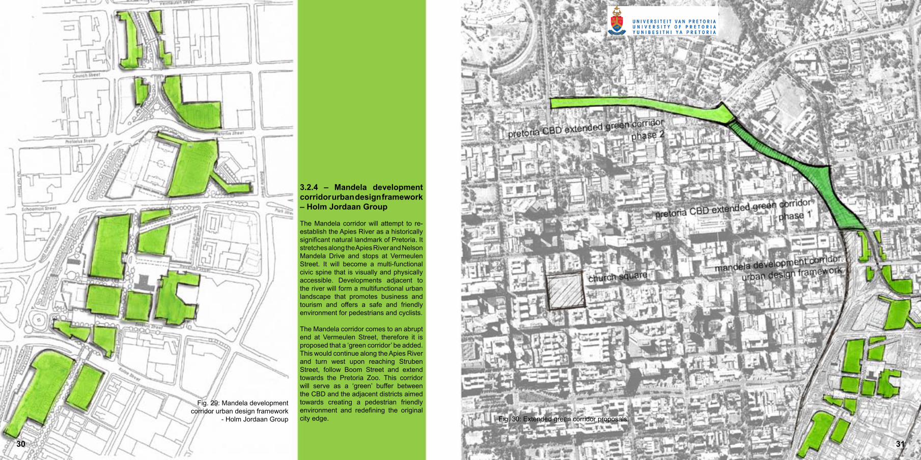
3.2.4 – Mandela development corridor urban design framework – Holm Jordaan Group
The Mandela corridor will attempt to re-establish the Apies River as a historically significant natural landmark of Pretoria. It stretches along the Apies River and Nelson Mandela Drive and stops at Vermeulen Street. It will become a multi-functional civic spine that is visually and physically accessible. Developments adjacent to the river will form a multifunctional urban landscape that promotes business and tourism and offers a safe and friendly environment for pedestrians and cyclists.
The Mandela corridor comes to an abrupt end at Vermeulen Street, therefore it is proposed that a ‘green corridor’ be added. This would continue along the Apies River and turn west upon reaching Struben Street, follow Boom Street and extend towards the Pretoria Zoo. This corridor will serve as a ‘green’ buffer between the CBD and the adjacent districts aimed towards creating a pedestrian friendly environment and redefining the original city edge.
Fig. 29: Mandela development corridor urban design framework
- Holm Jordaan Group Fig. 30: Extended green corridor proposals.
3130

The site is positioned on the northern side of a city block on the north-eastern corner of the Pretoria CBD. It is bordered by Struben Street, Du Toit Street, Proes Street, and Nelson Mandela Drive (Fig: 31; 32).
The site displays little evidence of its past (Fig.11). The infrastructure currently existing on and around the city block contains no original buildings and none of any historical significance. The last building of any importance was a single storey dwelling on the northern side of the city block last documented in 1991. This house has since been demolished (Le Roux and Botes 1991: x).
Traces of the history of the area are instead visible in the surrounding urban layout (Fig: 34; 35). To the east of the city block is a triangular piece of ground free from construction and covered with Jacaranda trees. It is surrounded by Nelson Mandela Drive, Struben Street, and Edward Street. This under-utilised piece of ground is reminiscent of the urban changes made over time and the conflicts facing design and natural barriers, in this case the Apies River. After the construction of Nelson Mandela Drive and the change of orientation to one-ways of many major roads in the Pretoria CBD, this piece of land was caught and lost between three roads. Since then, it has stood vacant serving mostly as an informal parking area for cars and taxis. This has allowed the trees growing on it to flourish.
Fig. 31: Aerial photo showing the position of the site in relation to Church Square.
Fig. 32: Aerial photo showing the position of the site in relation to the surrounding roads.
Fig. 33: Photo showing the site in 1948.
32 33

3.3.1 – Polemics
The Tshwane University of Technology (TUT) Arts Campus is positioned to the north of the site and separated from it by Struben Street. Being a major tertiary educational institution, this campus is of obvious value to its surroundings. Unfortunately the entire campus is fenced off with a 2,5 meter high pre-cast concrete wall that disrupts both physical and visual interaction between the inside and the outside of the campus (Fig. 36). The result is a non-responsive edge for the TUT campus influencing not only the campus itself and the pedestrian walkway bordering it, but also the visual interaction from the cars passing by on Struben Street and the site to the south.
Struben Street is a four lane one-way positioned north of the site that carries traffic to the east. Running parallel to it is Proes Street which is a four lane one-way carrying traffic west and positioned south of the site. Both these major city arteries intersect with Nelson Mandela Drive east of the block. In addition, the Apies River and the CBD edge join at this point and have resulted in somewhat awkward intersections. This makes it difficult for pedestrians to cross the roads at some points and it is in many ways a deterrent to movement (Fig: 38; 39).
The site has low building density with many of the buildings standing vacant. A fluorescent signage workshop owns approximately half the city block, yet only two single storey sheds and a double storey house cover less than 15% of the entire block leaving large portions of the site vacant. Medium density buildings, of which a large number are vacant, sit on the western side of the block bordering Du Toit Street. The only building on the entire block that is optimally utilised is the ABC Sweets wholesaler on the western side.
Problems existing in and around the city block have caused pedestrians to utilise alternative routes to that of Struben Street (Fig.37). Struben Street offers pedestrians using the taxi rank on the corner of Bloed and Van der Walt Streets a shorter route to Sunnyside and Arcadia. Ironically, the majority typically move south in Van der Walt Street and only start filtering east towards these destinations upon reaching Proes Street hence totally bypassing the site. This is because these routes provide facilities that cater for their needs whereas Struben Street does not (Fig: 40; 41).
Fig. 34: Aerial photo of the site in 1949.
Red indicates where Nelson
Mandela Drive was constructed
in later years. Green indicates
current lost piece of land.
Fig. 35: Aerial photo of site in 2005. Orange
stipple line indicates proposed
extension for Nelson Mandela
Road.
Fig. 36: TUT wall facing Struben Street.
3534

Fig. 37: Aerial photo showing the alternative routes prefered by pedestrians on their way to
sunnyside and/or arcadia from the taxi rank.
Fig. 38: Intersection between Nelson Mandela Road and Proes Street from Proes Street.
Fig. 39: Intersection between Nelson Mandela Road and Proes Street from Nelson Mandela Road.
Fig. 40: Informal facilities at taxi rank catering for pedestrians.
Fig. 41: Struben Street not catering for pedestrians.
36 37

The public spaces currently existing in Pretoria CBD has seen very little change in recent times. Since 1994 proposals have been made but no new projects have been undertaken and nothing has been added to the already insufficient structure.
Vehicular: The road grid in the Pretoria CBD runs perpendicular in a north south and east west orientation with a major ring road on the eastern and northern edges. A taxi rank is situated on the north-eastern border.
Train: The Pretoria Railway Station, south of the CBD, accommodates rail transport to Johannesburg (south), Mamelodi (west), and Atteridgeville (east). The Belle Ombre Railway Station on the northern side accommodates rail transport north and to Soshanguve.
Fig. 42: Transport system in Pretoria CBD 3.4 - Surrounding analysis3.4.1 - Transport 3.4.2 - Public spaces
Fig. 43: Public spaces in Pretoria CBD
3938

3.4.3 - Movement 3.4.4 - Surrounding usesFig. 44: Movement around the site. Red: Vehicular movement and intensity. Yellow: Pedestrian focus and intensity.
Fig. 45: Surrounding uses. Red: Commercial Yellow: Industrial Green: Institutional Blue: Residential
40 41

a. The building on the northern cor-ner of the city block is three storeys high and constructed from brick ma-sonry. It has office space on the first and second floors and retail space on the ground floor. Large parts of the building have been demolished and some parts even destroyed by fire. It is currently standing vacant and is of low economic value.
3.5 - Buildings on site
Fig. 46: Aerial photo showing buildings exisitng on the city block. Letters indicate buildings to be analysed. Numbers
indicate position from where photos were taken.
Fig. 47: Non responsive north facing facade.
Fig. 48: Barren piece of land east of the building. Traces of the old building can be seen in the remaining foundations.
4342
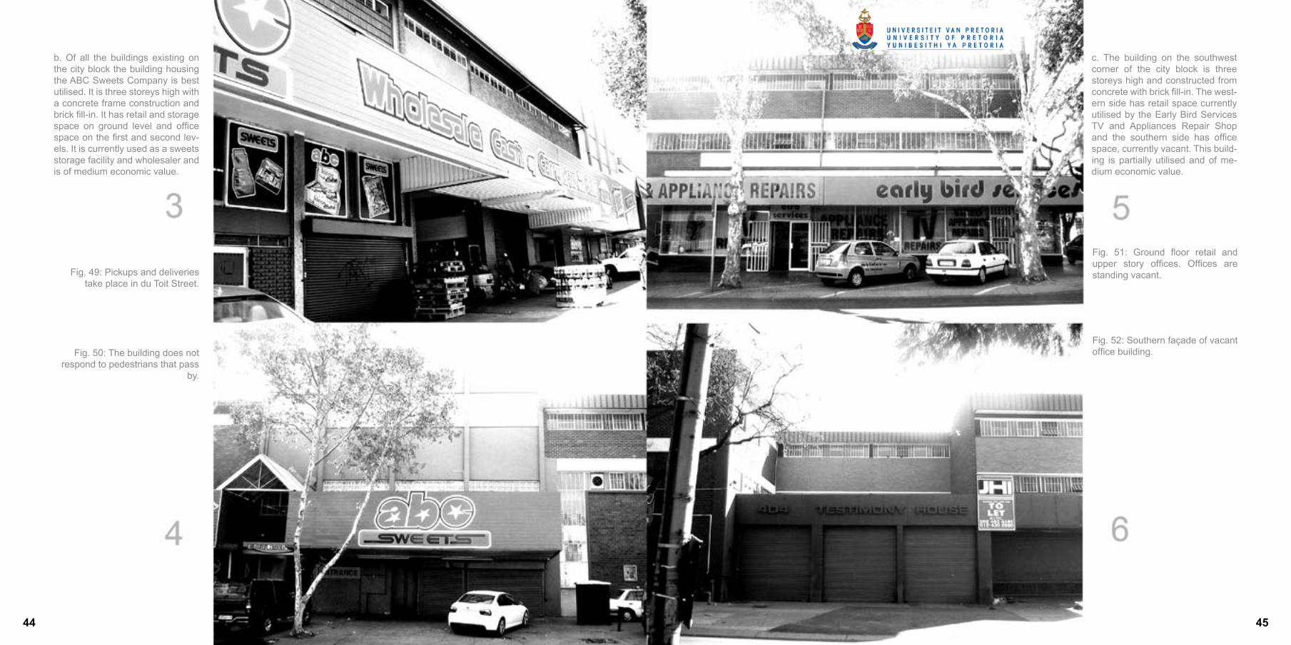
b. Of all the buildings existing on the city block the building housing the ABC Sweets Company is best utilised. It is three storeys high with a concrete frame construction and brick fill-in. It has retail and storage space on ground level and office space on the first and second lev-els. It is currently used as a sweets storage facility and wholesaler and is of medium economic value.
c. The building on the southwest corner of the city block is three storeys high and constructed from concrete with brick fill-in. The west-ern side has retail space currently utilised by the Early Bird Services TV and Appliances Repair Shop and the southern side has office space, currently vacant. This build-ing is partially utilised and of me-dium economic value.
Fig. 49: Pickups and deliveries take place in du Toit Street.
Fig. 50: The building does not respond to pedestrians that pass
by.
Fig. 51: Ground floor retail and upper story offices. Offices are standing vacant.
Fig. 52: Southern façade of vacant office building.
44 45

d. This building is double storey and constructed with brick masonry. The side of the building facing the street is currently used to manufacture number plates and the other side is used by the fluorescent sign manu-facturers. Adjacent to the building is a vacant piece of land only used for parking. This building is of low eco-nomic value. It is not stated where this building is situated.
e. These scattered buildings all form part of a fluorescent signage manufacturing workshop. A double storey face brick house stands on the south-eastern corner of the city block and has been converted into offices. A single storey shed con-structed from steel and corrugated iron is positioned on the north-east-ern side of the site and this is where production of the fluorescent signs takes place. The buildings are all used, but are of low density and hence of low to medium economic value.
Fig. 53: Street facing side of the building.
Fig. 54: Large piece of land west of the building. Not well utilised.
Fig. 55: House standing on the corner of Nelson Mandela Drive and Proes Street.
Fig. 56: Production shed with the Reserve Bank in the background.
4746

Fig. 57: Panoramic view of the city block from Struben Street.
48 49


4.1.1 Introduction
In contrast to the surrounding wineries that are focused towards extravagance, the client and the architects instead decided to take a different approach. The result was a building that is an exact rectangle, 140 meters long from north to south, 25 meters wide from east to west, and two storeys high. It was positioned on the backdrop of the farm’s vineyards and the simple form is only interrupted with two covered walkways that puncture through the width of the building separating the major functional spaces within.
The structure used is a simple and conventional concrete ground slab, concrete columns, and pre-cast concrete plank roof. The importance of the design lies in the cladding that consists of steel mesh cages and loosely packed stones, more commonly referred to as gabion walls. The reason the architects decided upon these gabions was not for aesthetic appeal only but rather their ability to regulate temperatures inside the building though thermal mass. By using different types and sizes of stones different parts of the building are regulated to different conditions.
4.1.2 – Considerations
The building uses passive cooling in a country and society where by and large, air conditioning is the norm. Only a small steel portion of the building containing the offices on the northern side is regulated mechanically. This supports the idea that, in many instances, passive ventilation can be optimised to such a degree that even very sensitive environmental requirements can be achieved with minimal mechanical resources. Herzog and de Meuron achieved this optimised passive thermal control through architecture and not through services.
Fig.59: Interior view of the Dominus Winery showing sunlight penetrating the gabion wall.
Fig.60: Exterior view of the Dominus Winery showing an undercover walkway puncuring throught the building
Her
zog
& d
e M
euro
n
4.1 – Herzog and de Meuron – Dominus Winery (California)
The Napanook Vineyard near Yountville, California has been cultivated since 1866. It was in 1983, that the wine produced there attracted such international acclaim that the proprietor Christian Moueix decided to build a winery on the site. In 1995, the family commissioned Herzog and de Meuron to design the building. Fig.58: Gabion wall with penetrating sunlight
5352

4.2 – Zaha Hadid – BMW Central Building (Leipzig)
In 2002, the German automotive company BMW invested in a $1, 55 billion competition for the design of the central building and factory of their complex on the outskirts of Leipzig, Germany. Twenty-five international architects participated in the competition and the brief was eventually awarded to Pritzker Prize winner Zaha Hadid. The brief set up by BMW required a building to cater for 5 000 employees and produce 650 3-series BMW’s per day. The first car rolled out of the factory in May 2005.
Zaha Hadid
Fig.61: Communal offices with conveyor belts suspended overhead transporting cars still in production phase.
Fig.62: Offices shared by managers and factory workers.
Fig.63: Inside walkway shoing conveyor belts suspended from the ceiling.
5554
4.2.1 Introduction
The central building proposed by Zaha Hadid is unique in terms of industrial conventions. BMW’s non-hierarchical culture of transparency and accessibility encouraged Hadid to create a democratic building where managers in authority not only share their entire working environment directly with that of the factory workers, but also in conjunction with the actual production process. Automotive production and administration is merged together with conveyor belts suspended from the roof moving cars, still in production phase, around the building and through the cafeteria, cubicles and laboratories. Initial criticism that such a direct integration of functions would not work successfully was proven incorrect when Peter Clausen, the Leipzig plant manager, pointed out that the conveyor belt in the cafeteria transporting dirty dishes to the kitchen was louder than the belt that moves cars through the building (Architectural record 08.05:90).
4.2.2 – Considerations
The architectural language used by Hadid is successful in that it communicates industrial success while it remains specifically committed to the slick and cool nature of the company. The inspiration drawn from this project is not the architecture per se but instead the concept of integrated functions in an industry. Users on all authority levels are able to work in the same environment, at all times aware of this living and active building surrounding them.

4.3 – Gabriel Fagan Architects – SAB visitors’ centre (Newlands)
The South African Breweries (SAB) operates a large beer production unit in Newlands in the Western Cape. The association with the site dates from 1956 when SAB merged with Ohlsson’s Cape Breweries and has since been developed into a successful beer trade for the area.
4.3.1 Introduction
Striving for tourist outreach in the area, the brewery decided to renovate the Mariendahl brewery built in 1859 and the malt house containing the kiln built in 1892, and convert them into a visitors’ centre.
The centre was designed by local architect Gabriel Fagan and reveals the important approach he took towards conservation. Instead of restoring original form, the re-use and contrasts between new and old were emphasised. The building takes the visitor on a journey of the history of the brewery and the history of brewing in the Cape. The journey is enhanced through symbolism, spatial experience and physical interaction (Architecture SA 09/10 1995:13–15).
4.3.1 – Considerations
The project focused on retaining heritage and conservation by means of expressing the modern. This has been achieved through contrast, and by the architectural language continuing to speak as a brewery revealing information to the visitors by means of a journey.
Fig.65: Inside of the visitors centre Fig.66: Special attention spent on detailing.
Fig.67: View of the lift.Fig.64: Front of the SAB Visitor Centre in Newlands. The new glass box in front contrasts the old brick chimney on the side.
Gabriel Fagan Architects
56 57

Fig.68: Concept Model July 2007

BREWERYBrew House
Control
Store Room
Reception/office
Laboratory
Brew Lab L1
Store room: B.L.L1
General brewers office: B.L.L1
Brew Lab L2
Store room: B.L.L2
Area containing the equipment necessary for the first phase of the brewing process. Contains the mash tun, lauter tun, and boiler.
User area for controlling the brewing process
Storage for brew house equipment
Reception foyer and reception office to the brewery for the public and the brewers
Infrastructure for beer research. Facilities for users to manage their products.
Open laboratory for research through means of small scale brewing. Intermediate brewers
General storage for brew lab L1
Open office with facilities for brewers to manage their business
Open laboratory for research through means of small scale brewing. Advanced brewers
General storage for brew lab L2
Visually accessible for pedestrians. Boiler needs to be visible.
Fire proof
Services required: Water from filter tanks; electricity; washable floors.
Fire proof
Fire proof
120 m²
25 m²
40m m²
125-150 m²
25 m²
40 m²
125-150 m²
25 m²
General brewers office: B.L.L1
Services
Mass Storage
Holding Bay 01
Holding Bay 02
Security Control/Office
Delivery yard
Kegging room
General Store Room
Control Office: Kegging
Processing room
Control Office: Processing room
Water Filter Room
Fermentation flasks
Plant room: fermentation flasks
Open office with facilities for brewers to manage their business
Contains processing equipment and services for the brewery
Storage of empty kegs, full kegs, raw materials for brewing purposes, processed materials for recycling
Regulating deliveries and pickups
Regulating deliveries and pickups
Regulate security at deliveries and pickups
Contains two delivery bays 1105 high, 3350 wide. Ramp @ 1:12
Finished processed beer stored in kegs.
General storage room for service block
Control and regulate kegging process
For the processing of yeast. Contains the yeast roaster and the yeast grinder
Controls and regulates the grinding and roasting processes
Contains water filter and tanks containing filtered water for use in the brew house, brewery labs, school labs
Contains 16 fermentation flasks. Phase two of brewing process.
Contains the chiller to cool the fermentation flasks
Not open to the public
Able to view Holding bay 01;02 and Mass Storage
Under coverAdjacent to Mass Storage
Adjacent to Mass Storage. Heat build up
Strict temperature regulation. Visually accessible to the public
40 m²
80-100 m²
20 m²
20 m²
5 m²
150 m²
100m²
20 m²
25 m²
100 m²
25 m²
80-100 m²
125 m²
30 m²
60 61

Pump room
Maturing room
Plant room: Maturing room
Brewing master’s office
Lounge
Security check
Offices
Ablution
Male
Female
School
Entrance Foyer
Security Check
Reception/office
Classroom 01
Classroom 02
Contains pump to pump beer from phase one to phase two and to pump cooled water from plant room to fermentation flasks
Contain 16 maturing flasks. Phase three of brewing process
Contains the chiller to cool the maturing room flasks
Office for the Brew master of the brewery
Lounge for brewers
Shared staff entrance for kitchen and the service block of the brewery
General offices
Ablution for all of the brewery, only accessible to the users
1xWC; 4xurinal; 4xbasin; 1xshower
3xWC; 4xbasins; 1xshower
Facilities to educate students
Central space leading to all areas of the school
Prevents unauthorised personnel from entering the school
Reception for the public and students to enterthe brewery and reception office
To seat 40 students
To seat 40 students
Strict temperature regulation. Visually accessible to the public
Contains lockers for all users
Separated from brewery by security access door
Accessible to the public
15 m²
85 m²
30 m²
10 m²
50 m²
30 m²
35 m²
20 m²
20 m²
50 m²
20 m²
35 m²
45 m²
45 m²
Circulation space
Administration officeSchool Brew Lab
Store Room: SBL
Kitchenette
Offices
Ablution
Male
Female
Public
Auditorium
Control room
Restaurant
Seating area: inside
Seating area: outside
Bar
Kitchen
Cold Room
Notice boards; information; display etc.
Responsible for school administrationOpen laboratory for research through small scale brewing by students
Storage for the school brew lab
Accessible to students
General administration and lecturer offices
For use by the students only. Ablutions for auditorium is shared with restaurant
1xWC; 3xurinal; 3xbasin
3xWC; 3xbasin
Facilities to educate the public
To seat 120
Regulate operations in auditorium.
Restaurant and Brew pub selling beer produced at the brewery and the school.
Tables and a bar
Benches
Serves drinks to waiters and serves directly to users
Complete kitchen
Walk in fridge for food
Fire proof
Open on to public space
Maturing flasks above bar need to be visually accessible.
Accessible from service area and kitchen
50 m²
30 m²150 m²
25 m²
15 m²
45 m²
15 m²
15 m²
150 m²
5 m²
180-200 m²
80-100 m²
50 m²
10 m²
BREWING SCHOOL BREW PUB & RESTAURANT
6362
Dry store
Washing
Preparation
Locker room
Chefs office
Ablution
Male
Female
Disabled
Storage for dry foods
Washing of dishes and other kitchen appliances
Where the food is prepared
For waiters, barman, cooks, Chef. Contains lockers for all employees; 1xWC; 1xshower.
Office for chef of the restaurant for regulation
Shared by the users of the auditorium
2 x WC; 5 x urinal; 5 x basin
4 x WC; 5 x basin
1 x WC; 1 x basin
Under cover platform for multiple uses. Shoulds for trading
Accessible from service area and kitchen
Adjacent to preparation area.
Have a view over all of the kitchen
Not accessible to the public
Creates a buffer between the road and public space
15 m²
10 m²
20 m²
10 m²
10 m²
15 m²
15 m²
3.5 m²
100 m²
ACTIVITY SPACE
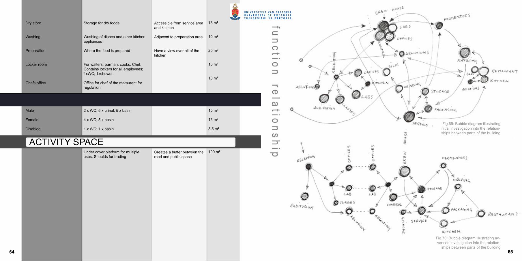
Fig.69: Bubble diagram illustrating initial investigation into the relation-ships between parts of the building
Fig.70: Bubble diagram illustrating ad-vanced investigation into the relation-
ships between parts of the building64 65

a. Buildings to be removed: The buildings that will be demolished on the site include the vacant office building on the northern edge, all the buildings forming part of the fluorescent sign manufacturing facility on the south-eastern corner, and the shared building on the southern side selling number plates. These buildings do not optimise the strengths and opportunities of the city block and have very limited potential in terms of expansion or addition.
b. Buildings to remain: The buildings that will remain on the city block include the ABC Sweet shop on the western side as well as the retail and office building on the south-western corner. These buildings are currently not well utilised but are capable of improving with relative ease. Demolition would not be economical at this stage.
c. Pedestrian movement on site: The city block is situated on the CBD edge and forms part of an extended green corridor aimed at an improved pedestrian environment. Movement on site will follow this green corridor leading pedestrians either down around the city edge or through the city edge. The green dots indicate destinations on site and off site whereas the green lines indicate the typical movement paths between destinations.
d. Vehicular movement: To the north and to the east of the city block are major roads that separate the city block from the TUT campus hostels to the north and Arcadia to the east. The orange arrows indicate direction of traffic flow.
5.3 – City block design
When considering the potential of the city block it becomes evident that most parts do not perform optimally. This, in conjunction with the new urban proposals for the Pretoria CBD, calls for the city block to be re-investigated and re-designed so as to optimise efficiency.
Fig.71: Remaining building on site. Fig.72: Movement after demolition.
6766

e. Hard edge: This edge of the city block is also the edge of the city CBD. It consists of Struben Street and Nelson Mandela Drive and creates an undesirable crossing point for pedestrians.
f. Visual and physical focus point: This is where pedestrians gather when crossing Struben Street from the TUT, or crossing Du Toit Street when moving east in Struben Street. This point is also an important visual focus point for all cars driving southeast in Boom Street and is visible up to the crossing with Bloed Street.
g. Pedestrian focus point: This point has the highest intensity of crossing pedestrian paths on the entire city block.
h. Green focus point: This point is a potential green space on the corner of the CBD. It has large trees standing on it and can optimally form part of the extended green corridor proposal.
i. Visual focus point: This point of the city block is an important visual focus point as it is visible while driving north in Nelson Mandela Drive and when driving west in Proes Street.
j. Walk path and central gathering point: The pedestrian focus point (g.) should become a social and public gathering space. Uninterrupted pedestrian flow should be accommodated between the corners of the city block (f. to i.) and through the public space.
k. Centralised service core: By focusing on pedestrians, services should be removed from the streets. A service yard will be reserved in the centre of the city block and be accessible from Proes Street. It will allow a rigid 16 tonne truck to enter and turn and will service all the buildings on the block.
Fig.73: Focus points. Fig.74: Walkway and service entance.
68 69

l. Solid: These buildings must have hard edges that respond to the walkway.
m. Transparent: These buildings must have transparent edges that respond to the walkway and serve as a buffer between it and the road.
A central service core is pro-posed around which the brew-ing processes flow in a circu-lar manner, ending where it started (Fig. 76; 77). The social interaction will be focused in the centre. By superimposing this placement of functions on to the site an initial form for the building can be derived (Fig. 78).
Fig.75: Building zones.
Fig.76: Process flow of brewery.
Fig.77: Process flow applied to site.
Fig.78: Process flow as generator of shape.
7170

Fig.79: Concept sketch June 2007.
5.5 Design development
Fig.80: Concept model May 2007.
Fig.81: Concept model May 2007.
72 73

Fig.82: Concept model June 2007.
Fig.83: Concept model June 2007.
Fig.84: Structural con-cept model July 2007.
Fig.85: Concept model June 2007.
7574
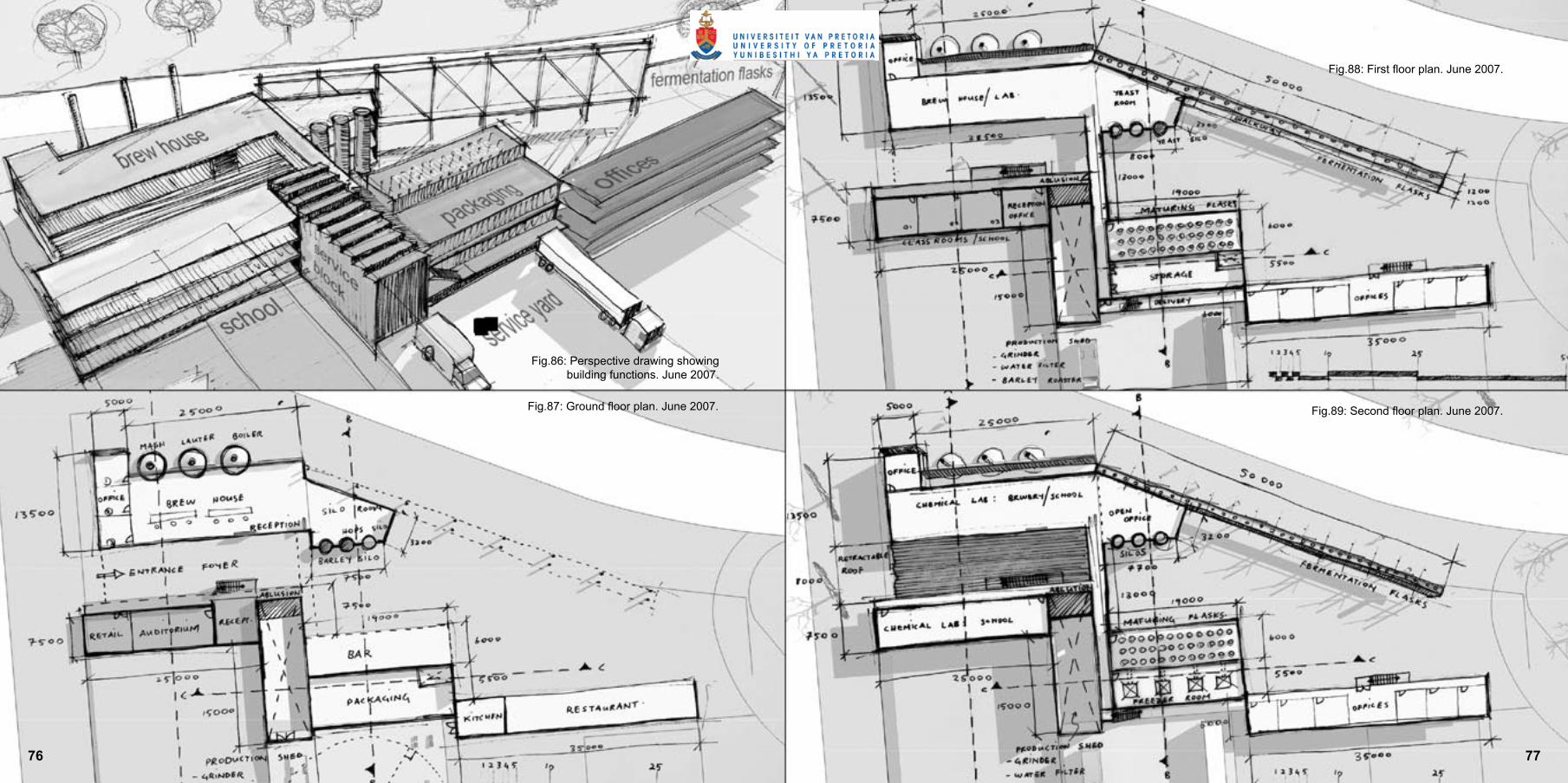
Fig.86: Perspective drawing showing building functions. June 2007.
Fig.87: Ground floor plan. June 2007.
Fig.88: First floor plan. June 2007.
Fig.89: Second floor plan. June 2007.
76 77

Fig.90: 3D rendering showing pedestrian movement past brew house.
Fig.91: 3D rendering showing pedestrian movement between the brewing school
and brew house.
Fig.92: 3D rendering showing pedestrian movement underneath fermentation flasks.
Fig.93: 3D rendering showing initial design for brew house and laboratories.
7978

Fig.98: 3d Model April 2007: View from public space Fig.99: 3d Model July 2007: School facade investigation
Fig.101: 3d Model April 2007: Walkway passing between the school on the right and the brew house on the left
Fig.100: 3d Model May 2007: Service yard with ramps and loading bays
Fig.94: 3d Model July 2007: School facade investigation.Fig.95: 3d Model July 2007: Interior view of brew house showing the boilers.
Fig.96: 3d Model July 2007: Back facade of Brew House.Fig.97: 3d Model July 2007: Front facade of Brew House
showing the chimneys.80 81

Fig.102: Conceptual north elevation August 2007.
Fig.103: Conceptual north elevation with solar screen August 2007.
8382

Fig.104: Ground floor plan.

Two types of steel construction are used in parts of the building where transparency is required (Fig. 107). The brew house and the area housing the maturing flasks are constructed with an H-section beam and column system. The H-sections are 254 x 254mm in size and positioned on a 7meter by 6 meter grid. The fermentation flasks adjacent to the activity platform are supported by 488 x 254mm steel columns constructed from 40 x 40mm steel equal leg angles (Fig. 105). The angles are arranged in a space frame made up of triangles.
6.1.1 s t e e l
Fig.105: Columns supporting the fermentation flasks.
Fig.106: Detailing
Fig.107: Parts of the building with a steel structure.
Fig.108: Steel structure used in the brew house.
86 87

The largest part of the building consisting of the brewing school and the services block of the brewery uses a reinforced concrete frame construction (Fig.:109;110). The columns are sized at 230 x 345mm, and the beams are 340mm deep. The grid spacing alters at different parts of the building with no span exceeding 7meters.
Conventional reinforced concrete slabs of 255mm are used in those parts of the building supported by a concrete frame construction (Fig: 114). Those areas where a steel frame construction is used, permanent shutter slabs are utilised (Fig:113).
Fig.109: Parts of the building with a concrete structure.
Fig.110: Concrete structure used in the services block and restaurant.
Fig.111: Aerial view showing floor slab.
Fig.112: Perspective view showing floor slab.
Fig.114: Concrete floor slab.
Fig.113: Permanent shutter concrete floor slab used in the
brew house.
8988

Concrete: Reinforced concrete roof slabs of 255mm are used in part of the building supported by a concrete frame construction. Permanent shutter concrete slabs are used in parts of the building with a steel structure.
Steel: 254 x 254 H-section beams sloped at a 5º are used in parts of the building with a steel frame construction. Trusses constructed from 40x40mm steel equal leg angles support the roof that suspends over the activity platform and are fixed to the same columns that support the fermentation flasks.
Fig.115: Aerial view showing placement of different roof types.
Fig.116: Detail of permanent shutter concrete roof used in the brew house.
Fig.117: Detail of steel roof covering the activity platform.
Fig.118: General detail of steel roof.
90 91

The general world view at present is largely focused towards sustainable development. In terms of thermal comfort, mechanical ventilation requires massive amounts of electricity and are major contributors to this problem. For this reason the building uses a passive ventilation system.
The design of the brewery allows cross ventilation to only be possible in the brew house. The school is placed flush to an existing building on the southern façade making cross ventilation impossible. For this reason ventilation ducks are ordered around the columns in a manner that allows all three levels to be passively ventilated. The ducts penetrate the first floor slab which opens to the auditorium, and draws in air though the floor. In the classrooms on the first floor, and in the research laboratory on the second floor, air is drawn into the room through the windows on the northern façade and out through the ventilation shafts on the southern side of the building.
In the brewery services block and restaurant, functions need to be physically separated. This does not allow for cross ventilation. In addition the distance from the southern side of the building to the northern side is too far for this process to work correctly, and ventilation in an east west direction is prevented for the same reason as in the school. Ventilation ducts are placed between the restaurant and services block drawing air through the northern façade of the restaurant and through the southern façade of the services block.
A service core of 6 x 4 meters is positioned in the middle of the building. It facilitates the sewerage pipes from the ablutions on all level and the extractor fans for the kitchen on the ground level. It is also a central control point from where filtered water moves to the brew house and laboratories. The service core is accessible on the ground floor from the kitchen and from the bridge on the first and second floor.
A second smaller service core of 1,4 x 1,7 meters is positioned between the maturing flask room and the services block. It facilitates the pipes carrying beer between the fermentation flasks and the maturing flasks. It is accessed from the ground level and is exposed on the first level to the kegging room.
Fig.121: Ventilation system in services block and restaurant.
Fig.122: Ventilation system in brewing school.
Fig.123: Ventilation system in brew house.
Fig.119: Services Red: Service cores Blue: Filtered water supply Green: Beer pipes
Fig.120: Ventilation shafts
9392

1. Fire exit2. Brew house3. Control panels4. Store room5. Employee ablution6. Pump room7. Lift8. Reception9. Entrance10. U/C activity platform11. Auditorium 12. Control room13. Foyer14. Reception office15. Entrance16. Male ablutions – Auditorium/Restaurant17. Paraplegic ablution – Auditorium/Restaurant18. Female ablution – Auditorium/Restaurant19. Service yard20. Cold room21. Kitchen preparation 22. Kitchen wash-up23. Locker room24. Dry store25. Restaurant managers office26. Service entrance 27. Security28. Refuse yard29. Mass storage30. Security office31. Holding bay 132. Holding bay 233. Raising platform34. Raising platform35. Delivery bay 136. Delivery bay 237. Ramp38. Bar storage39. Ventilation shafts40. Bar41. Restaurant42. Public walkway43. On street parking44. Struben Street45. Existing building
Fig.124: Ground floor plan.
94 95
6.6.1

1. Fire exit2. Balcony3. Store room for laboratory 4. Research laboratory 5. Chiller room L16. Lift7. Communal office for brewers8. Fermentation flasks x 169. Roof over activity platform10. Bridge11. Classroom 112. Classroom 1 storage13. Classroom 214. Classroom 2 storage15. Ventilation shaft16. Balcony17. School circulation – notice boards/information/display18. Open Office19. Office20. Service Yard21. Male ablutions for school22. Female ablutions for school23. Male ablutions for brewery24. Female ablutions for brewery25. Brew master’s office26. General storage for brewery27. Store room for kegging28. Lounge with lockers29. Control office for kegging30. Kegging room31. Ventilation shafts32. Maturing flasks x 1633. Balcony34. Intermediate storage between phases 35. Raising platform36. Existing building
Fig.125: First floor plan.
9796
6.6.2

1. Fire exit2. Balcony3. Store room4. Research laboratory5. Chiller room L26. Lift7. Communal office for brewers8. Walking platform to service fermentation flasks9. Bridge10. Balcony11. Ventilation shafts12. School research laboratory13. Store room for research laboratory14. Kitchenette 15. Male ablutions for brewery16. Female ablutions for brewery17. Service yard18. Water filter19. Tanks holding filtered water20. Control office for roaster and grinder21. Balcony22. Plant room for maturing room23. Maturing flasks x 1624. Grinder25. Roaster26. Ventilation shaft27. Raising platform28. Roof over service yard and holding bays29. Existing building
Fig.126: Second floor plan.
98 99
6.6.3
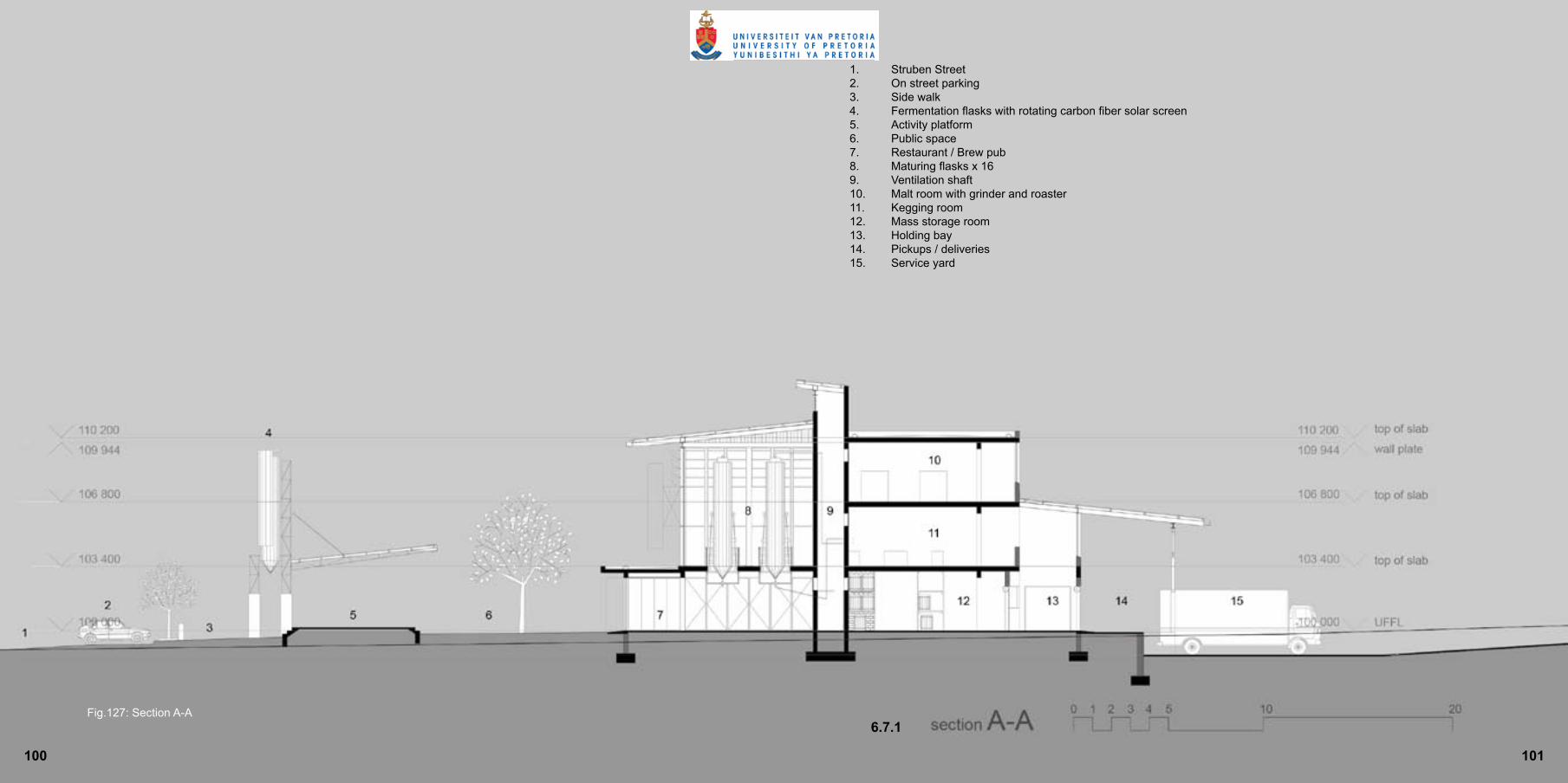
1. Struben Street2. On street parking3. Side walk4. Fermentation flasks with rotating carbon fiber solar screen5. Activity platform6. Public space7. Restaurant / Brew pub8. Maturing flasks x 169. Ventilation shaft10. Malt room with grinder and roaster11. Kegging room12. Mass storage room13. Holding bay14. Pickups / deliveries 15. Service yard
Fig.127: Section A-A
101100
6.7.1

1. Struben Street2. On street parking3. Side walk4. Brew house5. Research laboratory L16. Research laboratory L27. Public space8. Auditorium9. Class room10. School research laboratory 11. Ventilation shaft12. Existing building
Fig.128: Section B-B
102 103
6.7.2

Fig.129: North elevation.
105104

106 107
Fig.130: South elevation
108 109
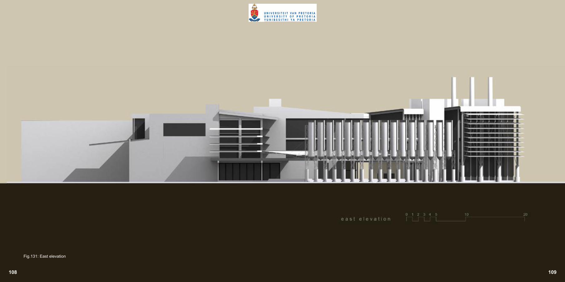
Fig.131: East elevation

110 111
Fig.132 West elevation

112 113

114
Bibliography
• ALLEN, V. 1971. Kruger’s Pretoria: Buildings and Personalities. Cape Town: AA. Balkema.• BARRENECHE, R,A. 20050800. Zaha Hadid Provides the Central Building. Architectural Record. vol.193/8: pg. 77-98• BETSKY, A. 19980400: Dominus winery, Yountville, California. Domus vol. 98/803: pg. 8-17• BRUYNS, G. J. B. 1998. Connected Isolation. Pretoria: University of Pretoria. • DE BEER, I. 19951000. SAB Visitor Centre - Newlands. Architecture S.A. vol.95/9/10: pg. 13-16• ENCYCLOPEDIA WIKIPEDIA. Beer. http://en.wikipedia.org/wiki/Beer (25th September 2007).• ENCYCLOPEDIA WIKIPEDIA. Pretoria. http://en.wikipedia.org/wiki/Pretoria (25 September 2007).• ENCYCLOPEDIA WIKIPEDIA. South African Beer. http://en.wikipedia.org/wiki/South_African_beer (1 October 2007).• FISHER, R. C. et al. 1998. Architecture of the Transvaal. Pretoria: University of Pretoria.• FLEMING, W. 1995. Arts and Idea. 9th edition. Texas: Harcourt Brace College Publishers.• HOLM JORDAAN GROUP. 2001. Mandela Development Corridor Urban Design Framework. Pretoria.• HOUGH, J. S. et al. 1971. Malting and brewing science. Great Britain: Richard Clay (the Chaucer Press).• JAPHA, V, et al. 19981100. SAIA Awards for Excellence 1998. SAB Visitros Centre. SA Architect. vol 1998/Nov: pg.26-29• JORDAAN, G. J. 1987. An Urban design strategy for place making in city centres. Johannesburg: University of the Witwatersrand. • KIRBY, A. 1982. The Politics of Location: An introduction. London: Methuen. • LECUTYER, A. 19981000: Steel, Stone and Sky. Architectural Review. vol.205/1220. pg. 44-48• LE ROUX, S. and BOTES, N. 1991. Plekke en Geboue van Pretoria: ‘n Oorsig van hulle argitektoniese en stede linge belang. Volume 2. Pretoria: Stadsraad van Pretoria.• NAPIER, A. 2000. Enviro-friendly methods in small building design for South Africa. Natal: Alaric Napier. • PEATTIE, L. 1981. Thinking about development. New York: Plenum Press. • PRETORIA: An Industrial and Commercial survey. 1962. South Africa: Felstar Publishing. • ROSE, A. H. 1977. Economic Microbiology. Volume 1. London: Academic Press. • SAMUELSSON, P. Finding the hidden breweries in South Africa. http://www.ratebeer.com/Story.asp?StoryID=602 Stockholm, Sweden (29 July 2007).• SLAVID, R. 20050519: Building study: Car Mechanics. Architects Journal. vol.221/19: pg.24-36• VAN JAARSVELD, F. A. 1985. Verstedeliking in Suid-Afrika. Pretoria: Gutenberg Boekdrukkers.
115
Figure 1: 3D rendering of brewery chimney by Karl Vogel Figure 2: Concept sketch May 2007 by Karl VogelFigure 3: 3D rendering of an area in Pretoria CBD by Karl VogelFigure 4: Ancient Egyptian painting showing people drinking beer (MARTINDALE, D)Figure 5: Photo of people selling locally brewed beer (MANFRED’S TRAVEL PICTURES)Figure 6: Photo of a brewing kettle. Major ingredients for brewing beer (MANFRED’S TRAVEL PICTURES)Figure 7: Flow diagram of the relationships between processes in a typical brewery by Karl VogelFigure 8: Flow diagram of the brewing process by Karl VogelFigure 9: Typical segregated South African city (VAN JAARSVELD, F, A. 1985)Figure 10: Pretoria 1948 Photo from Africana collection UP. Sketch by Karl VogelFigure 11: Pretoria 1970 Photo from Africana collection UP. Sketch by Karl VogelFigure 12: Metropolitan of Tshwane indicating major townships in grey and major industrial sectors in green by Karl VogelFigure 13: Old map of Pretoria showing major axes and bariers Photo from Africana collection UP. Sketch by Karl VogelFigure 14: Random concept sketches by Karl VogelFigure 15: Gauteng province by Karl VogelFigure 16: Tshwane metropolis by Karl VogelFigure 17: Pretoria CBD by Karl VogelFigure 18: Aerial photo showing study area Photo from GIS dept. UP. Sketch by Karl VogelFigure 19: Abandoned building by Karl VogelFigure 20: Barb wire fence surrounding Putco bus depot by Karl VogelFigure 21: Vacant land in Pretoria CBD by Karl VogelFigure 22: Rubbish bins by Karl VogelFigure 23 informal tyre market by Karl VogelFigure 24: Trash heaps by Karl VogelFigure 25: Vehicular oriented roads Photo from GIS dept. UP. Sketch by Karl VogelFigure 26: Pedestrian oriented roads Photo from GIS dept. UP. Sketch by Karl VogelFigure 27: Arcade system Photo from GIS dept. UP. Sketch by Karl VogelFigure 28: Tram lines and stations Photo from GIS dept. UP. Sketch by Karl VogelFigure 29: Mandela development corridor urban design framework (HOLM JORDAAN GROUP. 2001)Figure 30: Extended green corridor proposals Photo from GIS dept. UP. Sketch by Karl VogelFigure 31: Aerial photo showing the position of the site in relation to Church Square Photo from GIS dept. UP. Sketch by Karl VogelFigure 32: Aerial photo showing the position of the site in relation to the surrounding roads Photo from GIS dept. UP. Sketch by Karl VogelFigure 33: Photo showing the site in 1948 Photo from Africana collection UP. Sketch by Karl VogelFigure 34: Aerial photo of the site in 1949 Photo from Africana collection UP. Sketch by Karl Vogel Figure 35: Aerial photo of site in 2005 Photo from Africana collection UP. Sketch by Karl VogelFigure 36: TUT wall facing Struben Street by Karl VogelFigure 37: Aerial photo showing the alternative routes prefered by pedestrians on their way to sunnyside and/or arcadia from the taxi rank Photo from GIS dept. UP. Sketch by Karl Vogel
Figure 38: Intersection between Nelson Mandela Road and Proes Street from Proes Street by Karl Vogel
Figure 39: Intersection between Nelson Mandela Road and Proes Street from Nelson Mandela Road by Karl VogelFigure 40: Informal facilities at taxi rank catering for pedestrians by Marc JoosteFigure 41: Struben Street not catering for pedestrians by Karl VogelFigure 42: Transport system in Pretoria CBD Photo from GIS dept. UP. Sketch by Karl VogelFigure 43: Public spaces in Pretoria CBD Photo from GIS dept. UP. Sketch by Karl VogelFigure 44: Movement around the site. Photo from GIS dept. UP. Sketch by Karl VogelFigure 45: Surrounding uses. Photo from GIS dept. UP. Sketch by Karl VogelFigure 46: Aerial photo showing buildings exisitng on the city block. Photo from GIS dept. UP. Sketch by Karl VogelFigure 47: Non responsive north facing facade by Karl VogelFigure 48: Barren piece of land east of the building by Karl VogelFigure 49: Pickups and deliveries take place in du Toit Street by Karl VogelFigure 50: The building does not respond to pedestrians that pass by by Karl VogelFigure 51: Ground floor retail and upper story offices. Offices are standing vacant by Karl VogelFigure 52: Southern façade of vacant office building by Karl VogelFigure 53: Street facing side of the building by Karl VogelFigure 54: Large piece of land west of the building. Not well utilised by Karl VogelFigure 55: House standing on the corner of Nelson Mandela Drive and Proes Street by Karl VogelFigure 56: Production shed with the Reserve Bank in the background by Karl VogelFigure 57: Panoramic view of the city block from Struben Street by Karl VogelFigure 58: Gabion wall with penetrating sunlight (BETSKY, A. 19980400: pg. 16)Figure 59: Interior view of the Dominus Winery showing sunlight penetrating the gabion wall (BETSKY, A. 19980400: pg. 17)Figure 60: Exterior view of the Dominus Winery showing an undercover walkway puncuring throught the buildingFigure 61: Communal offices with conveyor belts suspended overhead transporting cars still in production phase (SLAVIR, R. 20050519: pg29)Figure 62: Offices shared by managers and factory worker (Berreneche, R,A. 20050800: pg.91)Figure 63: Inside walkway showing conveyor belts suspended from the ceiling (Berreneche, R,A. 20050800: pg.92)Figure 64: Front of the SAB Visitor Centre in Newlands (JAPHA, V, et al. 19981100: pg. 26)Figure 65: Inside of the visitors centre (DE BEER, I. 19951000: pg.16)Figure 66: Special attention spent on detailing (DE BEER, I. 19951000: pg.16)Figure 67: View of the lift (DE BEER, I. 19951000: pg.16)Figure 68: Concept Model July 2007 by Karl VogelFigure 69: Bubble diagram illustrating initial investigation into the relationships between parts of the building by Karl VogelFigure 70: Bubble diagram illustrating advanced investigation into the relationships between parts of the building by Karl VogelFigure 71: Remaining building on site by Karl VogelFigure 72: Movement after demolition by Karl VogelFigure 73: Focus points by Karl VogelFigure 74: Walkway and service entance by Karl VogelFigure 75: Building zones by Karl VogelFigure 76: Process flow of brewery by Karl VogelFigure 77: Process flow applied to site by Karl VogelFigure 78: Process flow as generator of shape by Karl VogelFigure 79: Concept sketch June 2007 by Karl VogelFigure 80: Concept model May 2007 by Karl Vogel Figure 81: Concept model May 2007 by Karl VogelFigure 82: Concept model June 2007 by Karl Vogel
116 117
List of Figures

118 119
Figure 83: Concept model June 2007 by Karl VogelFigure 84: Structural concept model July 2007 by Karl VogelFigure 85: Concept model June 2007 by Karl VogelFigure 86: Perspective drawing showing building functions. June 2007 by Karl VogelFigure 87: Ground floor plan. June 2007 by Karl VogelFigure 88: First floor plan. June 2007 by Karl VogelFigure 89: Second floor plan. June 2007 by Karl VogelFigure 90: 3D rendering showing pedestrian movement past brew house by Karl VogelFigure 91: 3D rendering showing pedestrian movement between the brewing school and brew house by Karl VogelFigure 92: 3D rendering showing pedestrian movement underneath fermentation flasks by Karl VogelFigure 93: 3D rendering showing initial design for brew house and laboratories by Karl VogelFigure 94: 3d Model July 2007: School facade investigation by Karl VogelFigure 95: 3d Model July 2007: Interior view of brew house showing the boilers by Karl VogelFigure 96: 3d Model July 2007: Back facade of Brew House by Karl VogelFigure 97: 3d Model July 2007: Front facade of Brew House showing the chimneys by Karl VogelFigure 98: 3d Model April 2007: View from public space by Karl VogelFigure 99: 3d Model July 2007: School facade investigation by Karl VogelFigure 100: 3d Model May 2007: Service yard with ramps and loading bays by Karl VogelFigure 101: 3d Model April 2007: Walkway passing between the school on the right and the brew house on the left by Karl VogelFigure 102: Conceptual north elevation August 2007 by Karl VogelFigure 103: Conceptual north elevation with solar screen August 2007 by Karl VogelFigure 104: Ground floor plan by Karl VogelFigure 105: Columns supporting the fermentation flasks by Karl VogelFigure 106: Detailing by Karl VogelFigure 107: Parts of the building with a steel structure by Karl VogelFigure 108: Steel structure used in the brew house by Karl VogelFigure 109: Parts of the building with a concrete structure by Karl VogelFigure 110: Concrete structure used in the services block and restaurant by Karl VogelFigure 111: Aerial view showing floor slab by Karl VogelFigure 112: Perspective view showing floor slab by Karl VogelFigure 113: Permanent shutter concrete floor slab used in the brew house by Karl VogelFigure 114: Concrete floor slab by Karl VogelFigure 115: Aerial view showing placement of different roof types by Karl VogelFigure 116: Detail of permanent shutter concrete roof used in the brew house by Karl VogelFigure 117: Detail of steel roof covering the activity platform by Karl VogelFigure 118: General detail of steel roof by Karl VogelFigure 119: Services by Karl VogelFigure 120: Ventilation shafts by Karl VogelFigure 121: Ventilation system in services block and restaurant by Karl VogelFigure 122: Ventilation system in brewing school by Karl VogelFigure 123: Ventilation system in brew house by Karl VogelFigure 124: Ground floor plan by Karl VogelFigure 125: First floor plan by Karl VogelFigure 126: Second floor plan by Karl VogelFigure 127: Section A-A by Karl VogelFigure 128: Section B-B by Karl VogelFigure 129: North elevation.
Figure 130: South elevationFigure 131: East elevationFigure 132: West elevation

120
Special thanx to Marc, Etienne, Marco, and Gisi.