subsystems $-- of the x-34 main propulsion ......winters1and champion 2. in addition, several x-34...
TRANSCRIPT

TRANS[N_E_ ANALYSIS OF PRESSURIZATION AND PNEUMATIC
SUBSYSTEMS OF THE X-34 MAIN PROPULSION SYSTEM$--
A. Hedayat and K C. Knight
Space Transportation Directorate
Sverdrup Technology, Inc. MSFC Group
Hunstville, AL 35806
R. H. Champion Jr.
Space Transportation Directorate
Marshall Space Flight Center
Huntsville, AL 35812
ABSTRACT
Transient models for the pressurization, vent/relief, and pneumatic subsystems of the X-34
Main Propulsion System are presented and simulation of their operation within prescribed
requirements are provided. First, using ROCket Engine Transient Simulation (ROCETS)
program, pressurization subsystem operation was simulated and helium requirements and the
ullage thermodynamic condition within each propellant tank were calculated. Then,
Overpressurization scenarios of propellant tanks and the response of vent/relief valves were
evaluated using ROCETS simulation of simultaneous operation of the pressurization and
vent/relief subsystems by incorporating the valves data into the model. Finally, the ROCETS
simulation of in-flight operation of pneumatic subsystem predicted the overall helium
consumption, Inter-Propellant Seal (IPS) purge flowrate and thermodynamic conditions, and
Spin Start power.
INTRODUCTION
The X-34 is a single stage Liquid Oxygen (LOX) and Rocket propellant 1 (RP-1) fueled
launch vehicle. The X-34 is carried for up to 2.5 hours in a horizontal captive carry mode.
This is done without resupply of propellant.. The main thrust for the vehicle is provided
by the MSFC developed FATRAC engine. It generates 60,000 lbf and 310 seconds of
specific impulse. The engine has a single shaft pump. The X-34 vehicle uses the L-1011
as the first stage to carry it to launch altitude of 38,000 ft for release. Once released, the
FASTRAC engine ignites at 7 seconds, when it has reached a safe distance from L-1011.
Then it transitions to vertical to exit the atmosphere. After burnout, the vehicle becomes a
glider for reentry. In the case of an aborted engine ignition, the vehicle must dump the
propellants to achieve landing weight. The Main Propulsion System (MPS) functions in
the loading, storing, delivery, and disposing of propellant. The MPS includes the LOX
and RP-1 feed, fill drain, dump, bleed, vent, relief, pressurization, and pneumatic
subsystems. An overview description of the X-34 MPS has been provided by Sgarlata and
https://ntrs.nasa.gov/search.jsp?R=20000093952 2020-02-07T17:30:53+00:00Z

Winters1and Champion 2. In addition, several X-34 MPS analyses are provided by Brown
et. al 3, Hedayat et. al 4, and McDonald et. al 5'6
PRESSURIZATION SUBSYSTEM ANALYSIS
The pressurization system is used to transfer propellants from the tanks to the turbopump
at the required fiowrates and pressures. The pressurization system is required to providesufficient helium in order to maintain the LOX and RP-1 tanks within the allowable
operational range. A schematic of the pressurization system is shown in Figure 1. The
Gaseous Helium (GHe) is stored in 4 bottles at an initial pressure then it is supplied to the
propellant tanks at limited flowrates using valves and regulators. In addition, solenoid
valves control the pressurization of the LOX and RP-1 tanks within the allowable pressure
range. Check valves are used to prevent any mixing of RP-1 and LOX, and to avoid the
consequence damages. The pressurant is introduced into the tanks through a diffuser,
which is designed to operate when submerged or dry. Helium is supplied to the propellant
tanks through two regulators. During the pressurization process, the second regulator is
considered to be completely open while the passage of the first regulator is adjusted such
that the pressure at the exit is maintained at a specified value. Initially, the regulator set
pressure was considered to be 350 psia but the test data indicated that for the set pressure
of 350 psia, a regulator lockup of 401 psia was required. While a lockup of 350 psia
provided a regulator set pressure of 314 psia. To perform analysis and to evaluate the
performance of the system, three different regulator set pressures, 314, 350, and 401 psia
were considered. In this analysis, the following assumptions were made:
,
.
.
.
.
.
7.
8.
.
10.
11.
12.
Helium initial temperature and pressure at ground loading are 530 °R and
5000 psia.
LOX temperature is 163 °R. LOX tank ullage pressure is 65 psia with a +3
psi control range.
Initial RP-1 tank temperature is 530 °R. The RP-1 tank ullage pressure is 50
psia with a +3 psi control range until the RP-1 tank contains 7.58 Ibm of
helium, at which time the helium mass is kept constant and the ullage is
allowed to expand at a specified rate.
RP-1 tank pressurization line has an ID of 0.65" (OD = 0.75"), and the rest
of the system has an ID of0.8Y' (OD -- 1").Densities of LOX and RP-I at described conditions are 71.5 Ibm/ff 3 and 50.5
lbm/t_ 3, respectively.
Volume of LOX and RP-1 tanks are 300 fi3 and 188.51 if3, respectively.
Use available Start transient flowrate data for the first 2.5 seconds.
RP-I tank initial ullage volume of 0.32 fi3 (0.5% of total RP-1 tank volume
is 0.96 fi3 which assume to fill three compartments equally).
LOX tank initial ullage volume is 4 fi3
Orifice diameter, located upstream of the RP-I tank, is 0.18 inch.Use vehicle internal environment data.
Duration of mainstage operation is 138 seconds.
13. With V'= volume flowrate, m '= mass flow rate, p = density, and V" = m 7p,
engine requirements during the steady state engine operating period are as
follows [8]:
Fluid_ m'(lbm/sec) V' (fl:3/sec)
LOX 144.0 2.014
RP-1 66.0 1.307
All LOX
Tank )--'k )
!RP-ITank
All Components are 0.75" 350 psia
1 heck Valve
[] Solenoid Valve
Pressure Regulator
[] Latching Solenoid Valve
_] Orifice
--O
_O Helium Bottles
_O 5000 psia
--O
Figure 1. Pressurization System Schematic
The ROCETS 7 model contains heat transfer mechanisms for the helium bottles, helium
lines, and propellant tanks. The response time of the solenoid valves and control system
are also modeled. The delay from the instant tank ullage pressure reaches the specified
set-point until a signal is sent to the solenoid valve is 0.05 second. The solenoid valve
closing/opening is considered to be linear. Initially the ullage pressures of the LOX and
RP-1 tanks are 62 psia and 53 psia, respectively.
The initial stored helium mass is 76 Ibm at 530°R and 5000 psia. During the ground
operations and captive carry periods, stored helium temperature and pressure drop to
501°R and 4726 psia due to significant temperature reduction due to the vehicle internalenvironment.
The ROCETS model was run for three diferrent cases. In the first case, the regulator exit
pressure is considered to be 350 psia. Figure 2 depicts the stored helium mass history
during the pressurization. The residual helium mass at the end of the pressurization
process is approximately 25.4 Ibm. The pressure history of the stored helium is shown in
Figure 3. At the end of the process, the helium pressure is approximately 822 psia. The
temperature history of the stored helium is illustrated in Figure 4. At the end of the
pressurization, the helium temperature is approximately 250°R. The LOX ullage pressure
history is shown in Figure 5. The LOX tank was maintained at 65 psia with a +3 psi
control range. The LOX ullage pressure reaches a maximum of 68.7 psia a_er 1.36
seconds.TheLOX tankullagemasshistoryis depictedinFigure6. This indicatesthat atthe endof the pressurizationprocess,theLOX tankcontains42.9 Ibmof helium.
Figure7 showsthe pressurehistoryof the ullage within the RP-1 tank. Initially, the ullage
pressure is 53 psia. The ullage reaches a maximum of approximately 54.7 psia after 2.52
seconds. After 114 seconds, the RP-1 tank contains 7.58 Ibm of helium as shown in
Figure 8. At this point, the solenoid valves are closed and the ullage mass is kept constant
until the end of the engine burn. At the end of the pressurization process, the RP-1 tank
ullage pressure is 39.3 psia.
For the second case, the regulator exit pressure is set at 314 psia. The LOX tank ullage
pressure is illustraed in Figure 9. The LOX tank ullage pressure range for this case is 68.7
to 61.7 psia. Figure 10 depicts the RP-1 tank ullage pressure during mainstage operation.
The RP-I ullage pressure range is between 54.5 and 46.6 psia, therefore, the
pressurization system provides sufficient helium supply to both propellant tanks within the
specified operational pressure range. The cycle times are longer and number of cycles isless than those of the first case.
In the third case, the regulator exit pressure is set at 401 psia. Figure 11 shows the LOX
tank ullage pressure history. The LOX tank maximum ullage pressure is 68.7 psia and
occurs at 1.2 second. Figure 12 provides the RP-1 tank ullage pressure history. The
pressure range is between 54.5 and 46.6 psia. The maximum ullage pressure is at 2.64
seconds. In this case the cycle times are the shortest while the number of cycles is the
highest of the three cases.
BO
70
60
50
_ 40
N 30
20
10
0
20 40 60 80 100 120 140
Time (s)
Figure 2. Stored Helium Mass History
400O
2000
1000
20 40 60 80 1O0 120 140
Time (s)
Figure 3. Pressure History of Helium Bottles
4

600
500
_, 400
111(1
o
0 20 40 60 80 100 120
Time (s)
70
60
50
20
lO
o140 0 20 40 60 80 100 120 140
Timc (,,)
Figure 4. Stored Helium Temperature History Figure 5. LOX Tank Pressure History(Regulator Exit Pressure = 350 psia)
50
40
10
0 20 40 60 80 100 120 140
Time (s)
6O
5O
4O
20
10
0
20 40 60 8O 100 120
Time (_)
140
Figure 6. LOX Tank Helium Mas History(Regulator Exit Pressure = 350 psia)
Figure 7. RP-I Tank Pressure History(Regulator Exit Pressure = 350 psia)
5

0 20 40 60 80 100 120 140
7O
6O
5O
20
10
0
20 40 60 80 1O0 120
Time (s) Tim= (s)
140
Figure 8. RP-I Tank Helium Mass History Figure 9. LOX Tank Pressure History(regulator Exit Pressure 314 psia)
60
50
4O
_ao
A_ 20
10
0 20 40 60 80 100 120 140
Time (s)
Figure 10. RP-I Tank Pressure History(Regulator Exit Pressure = 314 psia)
8O
7O
6O
_o
_ 30
2O
10
0
51]
40
20
10
01
20 40 60 80 100 120 140 0
Time (s)
20 40 60 80 100 120 140
Time (s)
Figure 11. LOX Tank Pressure History
(Regulator Exit Pressure = 401 psia)
Figure 12. RP-I Tank Pressure History
(Regulator Exit Pressure = 401 psia)
PROPELLANT TANKS VENT/RELIEF SUBSYSTEM ANALYSIS
In the event of a pressurization system solenoid valve(s) failure (fail open scenario), the
propellant tanks would have a potential risk of overpressurization. The overpressurization
could result in structural failure. The Vent/Relief (V/R) system on the propellant tank is
intended to relieve the ullage without allowing the tank pressure to rise above proof To
evaluate the performance of the V/R system and to verify the requirements for the test
data conditions, the analyses were carried out for the regulator exit pressure of 350 and
401 psia. Simultaneous operation of the pressurization and V/R systems, and performance
of the V/R system, were simulated using ROCETS. The ROCETS model simulated the
potential tank overpressurization due to failure of the solenoid located upstream of the
tank and the response of the V/R system.
If the solenoid valves fail open, the continuos flow of helium and its accumulation in the
tank lead to pressure build up and eventually potential overpressurization of the tank. As
the pressure reaches a specified value, the V/R valve is opened to allow ullage to leave,
therefore, relieving the pressure. In addition to assumptions provided m Pressurization
Subsystem Analysis section, to simulate the solenoid valve(s) failure and to evaluate the
potential tank overpressurization, the following assumptions were made:
.
,
The 2.5" Main V/R valve has a relief capacity of a 1.5" equivalent sharp-edged
orifice diameter (eseod) with a discharge coefficient of 0.60. The response
time for a complete cycle is 0.14 second (i.e., as tank pressure reaches 88 psia,
0.14 second later the valve is fully open).
By-pass V/R valves are similar with eseod of 0.35", and a discharge coefficient
of 0.6. The cracking pressure is 85 psia and the valve is fully open at a tank

,
4.
pressure of 98 psia (assume valve area variation is a linear function of tank
pressure, i.e., at pressure less than or equal to 85 psia, the area is zero; and as
the tank pressure reaches 98 psia, the valve is fully open).
No RP-1/LOX outflow from the tank.
Both propellant tanks have a proof pressure of 112.5 psia.
In this analysis, the failure of the solenoid valves (fail-open scenario) was simulated by
ROCETS for 2 different cases. For the first case, the regulator exit pressure was
considered to be at 350 psia. For the second case, a maximum of 401 psia was applied at
the regulator exit. For both simulation cases, the boundary conditions and thermodynamicstates are assumed to be the same.
For the cases in which the Main V/R valve is operating, as the propellant tank reaches 88
psia a delay equivalent to 0.14 second is imposed, then the Main V/R valve is set to open
fully, allowing the ullage to exit. As the ullage discharges from the tank, the pressure
within the tank drops. When the ullage pressure drops below 75 psia, the Main V/R valve
is closed. For the By-pass V/R valve(s) operational scenario, the valve cracking pressure
is set to 85 psia, and the valve(s) is (are) fully open as the tank pressure reaches 98 psia.
Figure 13 depicts the RP-1 tank ullage pressure history where regulator exit pressure is
assumed to be 350 psia. As the helium enters the tank, the tank pressure rises. When the
tank pressure reaches 85 psia, the By-pass V/R valve begins to open and when the
pressure reaches 98 psia, the By-pass valve is fully open. The By-pass V/R valve area is
assumed to be a linear function of the tank pressure. So, at the tank pressure equal (or
less than) to 85 psia, the valve area is set to zero, while at the tank pressure of 98 psia (or
higher), the valve is 100% open. In addition, 0.14 second after the tank reaches 88 psia,
the Main V/R valve is fully open. As the Main V/R valve opens, the ullage is allowed to
relieve at a greater rate. As the tank pressure drops below 85 psia, the By-pass V/R valve
closes while the Main V/R valve is open until the tank pressure drops below 75 psia, at
which point the Main V/R valve also is closed. The maximum RP-1 tank pressure is about
98 psia.
The LOX tank pressure history for regulator exit pressure of 350 psia is shown in Figure
14. The LOX Main V/R operation is similar to that of the RP-1 tank. As pressure
reaches 88 psia, a valve response time of 0.14 second is applied. So, as the tank pressure
reaches 88 psia, 0.14 second later the Main V/R valve is fully open and the ullage is
allowed to leave, therefore relieving the tank pressure. As the tank pressure drops below
75 psia, the Main V/R valve is closed. For this scenario, the maximum LOX tank ullage
pressure is 101 psia.
Figure 15 illustrates the RP-1 tank pressure history for the regulator exit pressure of 401
psia. The maximum tank ullage pressure is 98 psia. Figure 16 depicts the LOX tank
ullage pressure history for the regulator exit pressure of 401 psia. Maximum ullage
pressure for this case is 106 psia.

In all of the abovedescribedcases,the maximumRP-1or LOX tank ullage pressureisbelowtheproofpressureof 112.5psia.
120
,oo] 80
60
40
20
0 ) i
0.5 1 1.5 2 2,5 3
Time (s)
120
100
8O
2O
0
0.5 1 1.5 2 2.5
Time (s)
Figure 13. RP-I Tank Ullage Pressure History
(Regulator Exit Pressure =350 psia)
Figure 14. LOX Tank Ullage Pressure History
(Regulator Exit Pressure =350 psia)
&P
120
1O0
80
60
40
2O
0
0.5 1 1.5 2 2.5 3
Time (s)
Figure 15. RP-I Tank Ullage Pressure History
(Regulator Exit Pressure = 401 psia)
120
100
80
60
40
20
0
0 0.5 1 1.5 2 2.5
Time (s)
Figure 16. LOX Tank Ullage Pressure History
(Regulator Exit Pressure = 401 psia)
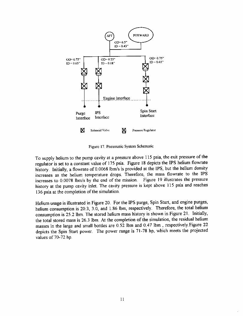
PNEUMATIC SYSTEM ANALYSIS
The pneumatic system is used for pneumatic valve actuation, Inter-Propellant Seal (IPS)
purges, engine Spin Start, and other engine purges. The helium pressure is regulated prior
to its use as a working fluid. The engine Spin Start process requires a high flow of helium
through the turbine to drive the pump during the engine start transient. The IPS purge is
required whenever propellants are provided to the engine to assure separation of RP-1 and
LOX in the single-shaft pump of the Fastrac engine. The pneumatic system operation was
simulated using ROCETS.
A schematic of the pneumatic system is shown in Figure 17. For the ROCETS transient
analysis of the pneumatic system, the following assumptions are made:
1. Initial helium temperature and pressure at ground loading are 530 °R and 5000
psia.
2. Helium usage for Spin provides 70-72 hp power at Spin Start.
3. At the end of Captive Carry, for the large bottle: pressure = 4726 psia,
temperature-- 501°R; for the small bottles: pressure = 4100 psia, temperature --
434 °R.
4. Volumes of large and small bottles are 6.2 ft3 and 2.2 tt 3 (1.1 ft3/bottle),
respectively.
5. Initial helium masses for the one large and two small bottles are 19 and 7.3 Ibm
(3.65 Ibm/bottle), respectively.
6. Average helium flowrate for the IPS purge = 0.007 lbm/s.
7. Pressure at the pump inlet _>115 psia.
8. The turbo-pump helium passages are considered as orifices with the following flow
characteristics: for RP-1 side, flow coefficient (Cd) = 0.7, area = 0.005 in2; for
LOX side, Cd = 0.5, area = 0.003 in 2.
9. Model duration (-900) to (1955) seconds (engine start @ time = 0),
Initially, the forward and aft bottles hold a total of 26.3 Ibm of helium at 5000 psia and
530 °R. The regulator in the IPS line reduces the pressure to 175 psia while the regulators
in the Spin Start and purge lines provide pressures of 1050 psia and 750 psia, respectively.
l0
...En_!net.nte.a..a_ .............
Purge IPS Spin StartInterface Interface Interface
] Solenoid Valve _ Pressure Regulator
Figure 17. Pneumatic System Schematic
To supply helium to the pump cavity at a pressure above 115 psia, the exit pressure of the
regulator is set to a constant value of 175 psia. Figure 18 depicts the IPS helium flowrate
history. Initially, a flowrate of 0.0068 lbm/s is provided at the IPS, but the helium density
increases as the helium temperature drops. Therefore, the mass flowrate to the IPS
increases to 0.0078 lbm/s by the end of the mission. Figure 19 illustrates the pressure
history at the pump cavity inlet. The cavity pressure is kept above 115 psia and reaches
136 psia at the completion of the simulation.
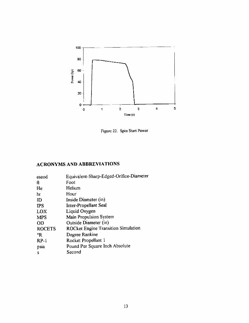
Helium usage is illustrated in Figure 20. For the IPS purge, Spin Start, and engine purges,
helium consumption is 20.3, 3.0, and 1.86 Ibm, respectively. Therefore, the total helium
consumption is 25.2 Ibm. The stored helium mass history is shown in Figure 21. Initially,
the total stored mass is 26.3 Ibm. At the completion of the simulation, the residual helium
masses in the large and small bottles are 0.52 Ibm and 0.47 Ibm, respectively.Figure 22
depicts the Spin Start power. The power range is 71-78 hp, which meets the projected
values of 70-72 hp.
11

09
k_
F
n4v,v.
0.009
0.008
0.007
0.006
0.005
0.004
0.003
0.002
0.001
-1000 -500 0
J
500 1000 1500
Time (s)
2OOO
80
4O
-1_0 -5_
,..,.t---
500 1000 1500 2000
Time(s)
Figure 18. Helium Flowrate for the IPS Purge Figure 19. Pump Cavity Pressure History
¢5
80-
25
20
15
10
-1ooo -500
...... Total
IPS purge
0 500 1000 1500 2000
Time(s)
EJ
3O
2_ 25 t _ Large bottle
_Small bottles
_Total
-1000 0 1000 2000
Time (s)
Figure 20. Helium Mass Used Figure 21. Stored Helium Mass
12
100
80
"E 60
o. 40
20
0 1 2 3 4 5
Time (s)
Figure 22. Spin Start Power
ACRONYMS AND ABBREVIATIONS
eseod
fi
He
hr
ID
IPS
LOX
MPS
OD
ROCETS
oR
RP-1
psiaS
Equivalent- Sharp-Edged-Orifice-DiameterFoot
Helium
Hour
Inside Diameter (in)
Inter-Propellant Seal
Liquid Oxygen
Main Propulsion System
Outside Diameter (in)
ROCket Engine Transition Simulation
Degree Rankine
Rocket Propellant 1
Pound Per Square Inch AbsoluteSecond
13
REFERENCES
1. Sgarlata, P. and Winters, B., (1997), "X-34 Propulsion System Design," AIAA paper
No., AIAA-97-3304.
2. Champion, R. H., Jr., and Darrow, R. J., Jr., (1998), "X-34 Main Propulsion System
Design and Operation,", MAA paper No. MAA-98-4032.
. Brown, T. M., McDonald, J. P., Hedayat, A., Knight, K. C., and Champion, R. H. Jr.,
(1998), "Propellant Management And Conditioning Within the X-34 Main Propulsion
System," MAA paper No., MAA-98-3518.
, Hedayat, A., Steadman, T. E., Brown, T. M., Knight, K. C., White, C. E., Jr., and
Champion, R. H., Jr., (1998), "Pressurization, Pneumatic, and Vent Subsystems of the
X-34 Main Propulsion System," AIAA paper No. AIAA-98-3519.
. McDonald, J. P., Minor, R. B., Knight, K. C., Russell, F. J., Jr., and Champion, R. H.,
Jr., (1998), "Propellant Feed Subsystem for the X-34 Main Propulsion System," MAA
paper No. MAA-98-3517.
6. McDonald, J. P., Hedayat, A., Brown, T. M., Knight, K. C., and Champion, R. H., Jr.,
(1998), "Subsystem Analysis/Optimization for the X-34 Main Propulsion System,"
7. "ROCETS User's Manual," Pratt and Whitney, West Palm Beach, FL, January 1995.
14