sun storedge 5210 nas hardware installation, configuration ... · viii sun storedge 5210 nas...
TRANSCRIPT
Sun Microsystems, Inc.www.sun.com
Submit comments about this document at: http://www.sun.com/hwdocs/feedback
Sun StorEdge™ 5210 NASHardware Installation,
Configuration, and User Guide
Part No. 817-6660-11November 2004, Revision A

PleaseRecycle
Copyright 2004 Sun Microsystems, Inc., 4150 Network Circle, Santa Clara, California 95054, U.S.A. All rights reserved.
Sun Microsystems, Inc. has intellectual property rights relating to technology that is described in this document. In particular, and without limitation, these intellectual property rights may include one or more of the U.S. patents listed at http://www.sun.com/patents and one or more additional patents or pending patent applications in the U.S. and in other countries.
This document and the product to which it pertains are distributed under licenses restricting their use, copying, distribution, and decompilation. No part of the product or of this document may be reproduced in any form by any means without prior written authorization of Sun and its licensors, if any.
Third-party software, including font technology, is copyrighted and licensed from Sun suppliers.
Parts of the product may be derived from Berkeley BSD systems, licensed from the University of California. UNIX is a registered trademark in the U.S. and in other countries, exclusively licensed through X/Open Company, Ltd.
Sun, Sun Microsystems, the Sun logo, AnswerBook2, docs.sun.com, Sun StorEdge, Java, and Solaris are trademarks or registered trademarks of Sun Microsystems, Inc. in the U.S. and in other countries.
All SPARC trademarks are used under license and are trademarks or registered trademarks of SPARC International, Inc. in the U.S. and in other countries. Products bearing SPARC trademarks are based upon an architecture developed by Sun Microsystems, Inc.
The OPEN LOOK and Sun™ Graphical User Interface was developed by Sun Microsystems, Inc. for its users and licensees. Sun acknowledges the pioneering efforts of Xerox in researching and developing the concept of visual or graphical user interfaces for the computer industry. Sun holds a non-exclusive license from Xerox to the Xerox Graphical User Interface, which license also covers Sun’s licensees who implement OPEN LOOK GUIs and otherwise comply with Sun’s written license agreements.
U.S. Government Rights—Commercial use. Government users are subject to the Sun Microsystems, Inc. standard license agreement and applicable provisions of the FAR and its supplements.
DOCUMENTATION IS PROVIDED "AS IS" AND ALL EXPRESS OR IMPLIED CONDITIONS, REPRESENTATIONS AND WARRANTIES, INCLUDING ANY IMPLIED WARRANTY OF MERCHANTABILITY, FITNESS FOR A PARTICULAR PURPOSE OR NON-INFRINGEMENT, ARE DISCLAIMED, EXCEPT TO THE EXTENT THAT SUCH DISCLAIMERS ARE HELD TO BE LEGALLY INVALID.
Copyright 2004 Sun Microsystems, Inc., 4150 Network Circle, Santa Clara, Californie 95054, Etats-Unis. Tous droits réservés.
Sun Microsystems, Inc. a les droits de propriété intellectuels relatants à la technologie qui est décrit dans ce document. En particulier, et sans la limitation, ces droits de propriété intellectuels peuvent inclure un ou plus des brevets américains énumérés à http://www.sun.com/patents et un ou les brevets plus supplémentaires ou les applications de brevet en attente dans les Etats-Unis et dans les autres pays.
Ce produit ou document est protégé par un copyright et distribué avec des licences qui en restreignent l’utilisation, la copie, la distribution, et la décompilation. Aucune partie de ce produit ou document ne peut être reproduite sous aucune forme, par quelque moyen que ce soit, sans l’autorisation préalable et écrite de Sun et de ses bailleurs de licence, s’il y ena.
Le logiciel détenu par des tiers, et qui comprend la technologie relative aux polices de caractères, est protégé par un copyright et licencié par des fournisseurs de Sun.
Des parties de ce produit pourront être dérivées des systèmes Berkeley BSD licenciés par l’Université de Californie. UNIX est une marque déposée aux Etats-Unis et dans d’autres pays et licenciée exclusivement par X/Open Company, Ltd.
Sun, Sun Microsystems, le logo Sun, AnswerBook2, docs.sun.com, Sun StorEdge, Java, et Solaris sont des marques de fabrique ou des marques déposées de Sun Microsystems, Inc. aux Etats-Unis et dans d’autres pays.
Toutes les marques SPARC sont utilisées sous licence et sont des marques de fabrique ou des marques déposées de SPARC International, Inc. aux Etats-Unis et dans d’autres pays. Les produits portant les marques SPARC sont basés sur une architecture développée par Sun Microsystems, Inc.
L’interface d’utilisation graphique OPEN LOOK et Sun™ a été développée par Sun Microsystems, Inc. pour ses utilisateurs et licenciés. Sun reconnaît les efforts de pionniers de Xerox pour la recherche et le développement du concept des interfaces d’utilisation visuelle ou graphique pour l’industrie de l’informatique. Sun détient une license non exclusive de Xerox sur l’interface d’utilisation graphique Xerox, cette licence couvrant également les licenciées de Sun qui mettent en place l’interface d ’utilisation graphique OPEN LOOK et qui en outre se conforment aux licences écrites de Sun.
LA DOCUMENTATION EST FOURNIE "EN L’ÉTAT" ET TOUTES AUTRES CONDITIONS, DECLARATIONS ET GARANTIES EXPRESSES OU TACITES SONT FORMELLEMENT EXCLUES, DANS LA MESURE AUTORISEE PAR LA LOI APPLICABLE, Y COMPRIS NOTAMMENT TOUTE GARANTIE IMPLICITE RELATIVE A LA QUALITE MARCHANDE, A L’APTITUDE A UNE UTILISATION PARTICULIERE OU A L’ABSENCE DE CONTREFAÇON.
Radio/TV Interference StatementThis equipment has been tested and found to comply with the limits for a Class A digital device, pursuant to Part 15 of the FCC Rules. These limits are designed to provide reasonable protection against harmful interference when the equipment is operated in a commercial environment. This equipment generates, uses, and can radiate radio frequency energy and, if not installed and used in accordance with the instructions in this user’s guide, may cause harmful interference to radio communications. Operation of this equipment in a residential area is likely to cause harmful interference, in which case the user will be required to correct the interference at his own expense.
If interference is noticed, consult your computer system user’s guide for radio interference information. Generally, eliminating the interference involves reorienting the antenna, moving the computer away from the receiver, or plugging the receiver into a different outlet from that of the computer.
The FCC has prepared a booklet titled “How to Identify and Resolve Radio-TV Interference Problems” which you may find useful. It is available from the US Government Printing Office, Washington, D.C. 20402, Stock No. 004-000-00345-4.
Canadian Department of Communications Compliance Statement:This equipment does not exceed Class A limits per radio noise emissions for digital apparatus set out in the Radio Interference Regulation of the Canadian Department of Communications. Operation in a residential area may cause unacceptable interference to radio and TV reception, requiring the owner or operator to take whatever steps are necessary to correct the interference.
Avis de conformite aux normes du ministere des Communications du Canada:Cet equipment ne depasse pas les limites de Classe A d'emission de bruits radioelectriques pour les appareils numeriques telles que perscrites par le Reglement sur le brouillage radioelectrique etabli par le ministere des Communications du Canada. L'exploitation faite en milieu residentiel peut entrainer le brouillage des receptions radio et television, ce qui obligerait le proprietaire ou l'operateur a prendre les dispositions necessaires pour en eliminer les causes.
iii

iv Sun StorEdge 5210 NAS Hardware Installation, Configuration, and User Guide • November 2004

Contents
1. Introduction 1
Sun StorEdge 5210 NAS Technology: An Introduction 1
Sun StorEdge 5210 NAS Features 2
Setup Posters 4
Conventions Used in This Manual 4
Contacting Technical Support 5
Where to Go from Here 5
2. Installing the Sun StorEdge 5210 NAS 7
Before You Begin 8
Unpacking the Sun StorEdge 5210 NAS and/or Expansion Unit(s) 9
Sun StorEdge 5210 NAS Front and Back Panels 11
Expansion Unit Front & Back Panels 12
Rack-Mounting the Sun StorEdge 5210 NAS/Expansion Unit 13
Connecting to Networks 17
Connecting Each Expansion Unit Chassis to an AC Power Outlet 21
Powering On the Sun StorEdge 5210 NAS and Expansion Unit(s) 23
3. Using the Sun StorEdge 5210 NAS 27
Sun StorEdge 5210 NAS Components 27
Contents v

Expansion Unit Components 36
A. Specifications 39
Sun StorEdge 5210 NAS and Expansion Unit Technical Specifications 39
Glossary 41
Index 45
vi Sun StorEdge 5210 NAS Hardware Installation, Configuration, and User Guide • November 2004

Figures
FIGURE 2-1 Sun StorEdge 5210 NAS Front View 11
FIGURE 2-2 Sun StorEdge 5210 NAS with Faceplate Removed 11
FIGURE 2-3 Sun StorEdge 5210 NAS Back Panel with One RAID Card 11
FIGURE 2-4 Expansion Unit Front View 12
FIGURE 2-5 Expansion Unit with Faceplate Removed 12
FIGURE 2-6 Expansion Unit Back Panel 12
FIGURE 2-7 Recommended Rack Mounting Order 15
FIGURE 2-8 Connecting to Ethernet Networks 17
FIGURE 2-9 Connecting the Sun StorEdge 5210 NAS and a Single Expansion Unit 18
FIGURE 2-10 Connecting the Sun StorEdge 5210 NAS and Two Expansion Units 19
FIGURE 2-11 Connecting the Sun StorEdge 5210 NAS and Three Expansion Units 20
FIGURE 2-12 AC Cord Lock 21
FIGURE 2-13 Installed Cord Lock 22
FIGURE 2-14 Expansion Unit Back Panel 24
FIGURE 2-15 Connecting the Sun StorEdge 5210 NAS AC Power Cables 25
FIGURE 2-16 Power Switch and Front Panel Detail 25
FIGURE 3-1 Sun StorEdge 5210 NAS with Drive Shuttles 28
FIGURE 3-2 Sun StorEdge 5210 NAS Network Interface Card Ports 29
FIGURE 3-3 Sun StorEdge 5210 NAS Power Supply 30
FIGURE 3-4 Power Switch and Front Panel Detail 31
FIGURE 3-5 Sun StorEdge 5210 NAS Back Panel Ports and Connectors 33
vii

FIGURE 3-6 Sun StorEdge 5210 NAS with Two RAID Cards 34
FIGURE 3-7 Sun StorEdge 5210 NAS VGA Port 35
FIGURE 3-8 Expansion Unit with Front Cover Removed 36
FIGURE 3-9 Sun StorEdge 5210 Expansion Unit Drive Shuttle 37
FIGURE 3-10 Expansion Unit Power Supply Modules 37
viii Sun StorEdge 5210 NAS Hardware Installation, Configuration, and User Guide • November 2004

CHAPTER 1
Introduction
Thank you for purchasing the Sun StorEdge™ 5210 NAS, the Sun Microsystems network-attached storage solution.
This chapter provides introductory information about the Sun StorEdge 5210 NAS features. It also explains how this user guide is organized, and how best to use it to help you get started.
Sun StorEdge 5210 NAS Technology: An IntroductionFor corporate workgroups and departments who require the ability to share documents across heterogeneous platforms in an easily managed environment, the Sun StorEdge 5210 NAS provides a highly reliable, easily installed, fundamental piece in a complete End-to-End network storage solution.
Supporting file sharing between UNIX® and Windows environments, the Sun StorEdge 5210 NAS significantly accelerates file I/O services, ensuring data integrity by relying on a full-journaling file system. Application server performance is also optimized by off-loading data sharing responsibilities.
Sun StorEdge 5210 NAS attaches directly to the network as quickly and simply as a network printer. With high-speed CPUs and high-speed RAID controller architecture – to boost performance – as well as redundant components that improve data availability, the modular, scalable Sun StorEdge 5210 NAS offers high levels of performance for users who require optimum file sharing capabilities.
The expansion units are optional expansion modules that connect to the Sun StorEdge 5210 NAS and provide additional storage. You can install up to three expansion units to increase storage capacity.
1

Sun StorEdge 5210 NAS Features
Note – For the most current support information, please contact your Sun sales representative.
Supported File Access Protocols■ Microsoft networks (CIFS/SMB)■ UNIX (NFS), V2 and V3■ File Transfer Protocol (FTP)
Network Security/ProtocolsIntegrates with:
■ Windows Domain Controller■ Network Logon (Netlogon) client■ Windows Domain support■ Multiple Master Domain (MMD) support■ CIFS Security Descriptors (SD) on file and directories■ Discretionary Access Control Lists (DACL) on files and directories■ NIS■ NIS+■ Unicode■ Windows Active Directory Service (ADS) support■ Windows Dynamic DNS support■ Windows-compatible Kerberos (v5) security■ Windows-compatible Lightweight■ Microsoft-compatible LDAP■ LDAP authentication for NFS
Supported Clients■ Microsoft Windows NT 4.0/2000/XP/2003■ Solaris™ 2.6, 7, 8, 9 and 9x86 Operating System■ IBM AIX 5.1■ HP HP-UX 11i
2 Sun StorEdge 5210 NAS Hardware Installation, Configuration, and User Guide • November 2004

■ Red Hat Linux Enterprise Edition 2.1■ SUSE Linux Server 9
Network Connection■ Auto-sensing 10/100/1000 Base-TX, dual RJ-45 network connector■ Optional Fibre/Copper Gigabit Ethernet
Automatic IP Address Assignment■ Supports DHCP, ARP, for automatic assignment of IP address
Hardware RAID Subsystem■ Multiple file system options■ The Sun StorEdge 5210 NAS is configured for maximum file protection using
hardware RAID 5 (disk striping with parity)
Data Management■ Sun StorEdge File Checkpoint facility allows users to recover accidentally
damaged or deleted data with a simple file copy operation■ Directory Tree Quotas■ User and Group Quotas
Setup and Configuration■ SNMP MIB■ Web-Based User Interface for System Administration■ Menu-Based Telnet Interface
Client Data Backup■ Network Data Management Protocol (NDMP), V2 and V3■ Network Backup■ BakBone NetVault 7, supported by BakBone■ Compatible with Solaris backup software, including Veritas NetBackup and Sun
StorEdge Enterprise Backup Software
Chapter 1 Introduction 3

Setup PostersCheck the Sun StorEdge 5210 NAS package for an easy “Setup Poster” about the Sun StorEdge 5210 NAS.
The expansion unit package includes a poster for connecting the expansion unit(s).
Conventions Used in This ManualThis manual was designed to make it easy for you to find the information you need quickly. To help guide you on your way, familiarize yourself with the following icons.
TABLE 1-1 Conventions Used in Guide
Caution
Indicates steps or procedures that could result in loss of data or damage to hardware if not followed.
Note More fully explains a point in the text which might be missed or need further clarification.
Warns you that antistatic grounding procedures should be followed before continuing the installation.
Points out a section where you may need the help of trained technical support personnel, or gives information on how to contact other resources.
Reminds you to keep the screws you are removing in the procedure, as you will need them again to complete the installation or replacement.
Click Press the left mouse button.
Enter Words in boldface type represent keystrokes, menu items, window names or mouse commands.
��
4 Sun StorEdge 5210 NAS Hardware Installation, Configuration, and User Guide • November 2004

Contacting Technical SupportFor technical problems requiring on-site service, Sun Microsystems provides professional, experienced field engineers, who work closely with our Technical Support Engineers for total solution support. For more information about purchasing an on-site service package for your system, contact your sales representative or reseller.
You can contact Sun Microsystems Technical Support Engineers in a variety of ways or obtain technical information (specifications, files, answers to frequently asked questions) by going to http://www.sun.com/service/contacting/solution.html.
Where to Go from HereChapter Two: Installing the Sun StorEdge 5210 NAS—Provides instructions for installing the Sun StorEdge 5210 NAS and expansion units.
Chapter Three: Using the Sun StorEdge 5210 NAS—Describes how to use the Sun StorEdge 5210 NAS and its components. It is organized into two sections: internal components and external components.
Appendix: Specifications—Provides information about physical and environmental characteristics as well as power requirements for the Sun StorEdge 5210 NAS.
Glossary—Gives definitions for unfamiliar words you might find in this user’s guide.
Index—Lists topics alphabetically for quick reference.
Disk Drives Disk drives, such as drive A, drive C or network drives, are referred to as A:, C:, etc.
Commandsand Prompts
Words in Courier type indicate commands or prompts provided by the computer or server.
Commands Words in boldface Courier type indicate commands you should type.
TABLE 1-1 Conventions Used in Guide
Chapter 1 Introduction 5

6 Sun StorEdge 5210 NAS Hardware Installation, Configuration, and User Guide • November 2004
CHAPTER 2
Installing the Sun StorEdge 5210 NAS
This chapter provides comprehensive instructions for installing the Sun StorEdge 5210 NAS and the optional expansion units. It has been designed to help you:
■ Check for required components■ Unpack the Sun StorEdge 5210 NAS and expansion unit(s)■ Rack-mount the Sun StorEdge 5210 NAS and expansion unit(s)■ Power on the Sun StorEdge 5210 NAS and expansion unit(s)
Note – The Sun StorEdge 5210 NAS ships with the operating system installed.
7

Before You BeginBefore proceeding with the hardware installation, please take a moment to make sure your Sun StorEdge 5210 NAS package includes the following listed items. Should any of the items be damaged or missing, contact your Sun Microsystems sales representative or reseller immediately.
Sun StorEdge 5210 NAS filer
Setup Poster
Product documentation CD-ROM
AC Power Cords (These must be ordered separately from Sun Microsystems.)
Rail-mounting kit (This must be ordered separately from Sun Microsystems.)
8 Sun StorEdge 5210 NAS Hardware Installation, Configuration, and User Guide • November 2004
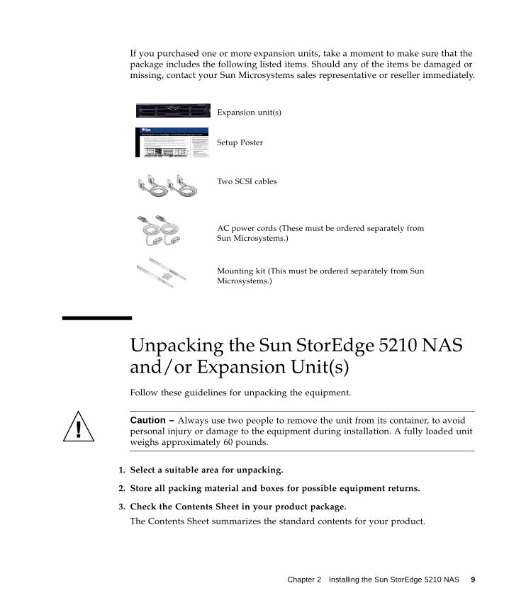
If you purchased one or more expansion units, take a moment to make sure that the package includes the following listed items. Should any of the items be damaged or missing, contact your Sun Microsystems sales representative or reseller immediately.
Unpacking the Sun StorEdge 5210 NAS and/or Expansion Unit(s)Follow these guidelines for unpacking the equipment.
Caution – Always use two people to remove the unit from its container, to avoid personal injury or damage to the equipment during installation. A fully loaded unit weighs approximately 60 pounds.
1. Select a suitable area for unpacking.
2. Store all packing material and boxes for possible equipment returns.
3. Check the Contents Sheet in your product package.
The Contents Sheet summarizes the standard contents for your product.
Expansion unit(s)
Setup Poster
Two SCSI cables
AC power cords (These must be ordered separately from Sun Microsystems.)
Mounting kit (This must be ordered separately from Sun Microsystems.)
Chapter 2 Installing the Sun StorEdge 5210 NAS 9

4. Compare the packing slip and the list of parts with the items you received.
If the list of parts on your packing slip does not match the items you received, or any items appear damaged, immediately notify your carrier agent and the supplier who prepared your shipment.
5. Carefully examine the cables provided in the package.
If any cable appears to be damaged, contact the Technical Service department for an immediate replacement.
6. Make sure you have provided the following cables required to complete the installation:
For the Sun StorEdge 5210 NAS:
■ Two 3-prong AC power cables.
For the expansion unit:
■ Two 3-prong AC power cables.
■ Two ultra high-density SCSI cables .
To obtain qualified cables, consult your Sun Microsystems sales representative.
10 Sun StorEdge 5210 NAS Hardware Installation, Configuration, and User Guide • November 2004

Sun StorEdge 5210 NAS Front and Back Panels
FIGURE 2-1 Sun StorEdge 5210 NAS Front View
FIGURE 2-2 Sun StorEdge 5210 NAS with Faceplate Removed
FIGURE 2-3 Sun StorEdge 5210 NAS Back Panel with One RAID Card
AC Power Supply 1
SCSI Port to optional
VGA*
Keyboard*
USB (reserved)
Built-in
AC Power Supply 2
AC Power Plugs
USBUPS(reserved)
* maintenance useNICs
expansion unitSCSI Port (internal)
SCSI Port for optional local tape
Optional fiber NIC
Chapter 2 Installing the Sun StorEdge 5210 NAS 11

Expansion Unit Front & Back Panels
FIGURE 2-4 Expansion Unit Front View
FIGURE 2-5 Expansion Unit with Faceplate Removed
FIGURE 2-6 Expansion Unit Back Panel
Power SwitchPower Switch
AC Power Plug AC Power PlugChannel 1
Channel 2 Connectors (jumper for expansion unit)
SCSI Connector(to Sun StorEdge 5210 NAS)
unused
12 Sun StorEdge 5210 NAS Hardware Installation, Configuration, and User Guide • November 2004
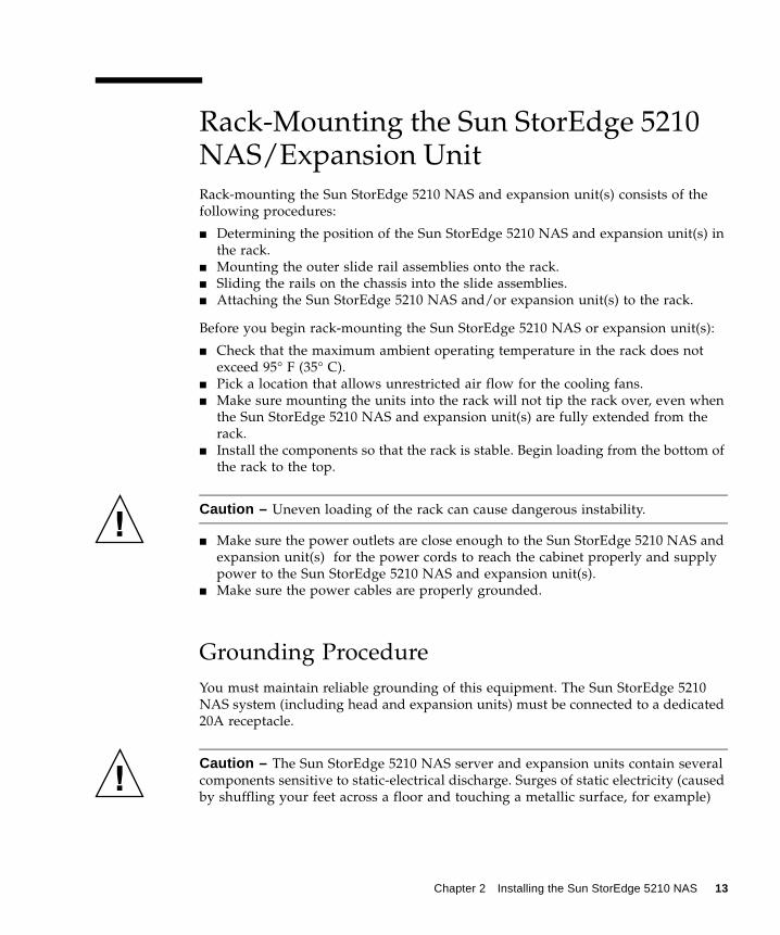
Rack-Mounting the Sun StorEdge 5210 NAS/Expansion UnitRack-mounting the Sun StorEdge 5210 NAS and expansion unit(s) consists of the following procedures:
■ Determining the position of the Sun StorEdge 5210 NAS and expansion unit(s) in the rack.
■ Mounting the outer slide rail assemblies onto the rack.■ Sliding the rails on the chassis into the slide assemblies.■ Attaching the Sun StorEdge 5210 NAS and/or expansion unit(s) to the rack.
Before you begin rack-mounting the Sun StorEdge 5210 NAS or expansion unit(s):
■ Check that the maximum ambient operating temperature in the rack does not exceed 95° F (35° C).
■ Pick a location that allows unrestricted air flow for the cooling fans.■ Make sure mounting the units into the rack will not tip the rack over, even when
the Sun StorEdge 5210 NAS and expansion unit(s) are fully extended from the rack.
■ Install the components so that the rack is stable. Begin loading from the bottom of the rack to the top.
Caution – Uneven loading of the rack can cause dangerous instability.
■ Make sure the power outlets are close enough to the Sun StorEdge 5210 NAS and expansion unit(s) for the power cords to reach the cabinet properly and supply power to the Sun StorEdge 5210 NAS and expansion unit(s).
■ Make sure the power cables are properly grounded.
Grounding ProcedureYou must maintain reliable grounding of this equipment. The Sun StorEdge 5210 NAS system (including head and expansion units) must be connected to a dedicated 20A receptacle.
Caution – The Sun StorEdge 5210 NAS server and expansion units contain several components sensitive to static-electrical discharge. Surges of static electricity (caused by shuffling your feet across a floor and touching a metallic surface, for example)
Chapter 2 Installing the Sun StorEdge 5210 NAS 13
can cause damage to electrical components. For this reason, it is important that proper packaging and grounding techniques be observed. Follow the procedures below.
■ Transport products in static-safe containers.■ Cover work stations with approved static-dissipating material.■ Wear a wrist strap, and always be properly grounded when touching static-
sensitive equipment/parts.■ Use only properly grounded tools and equipment.■ Avoid touching pins, leads, or circuitry.
To avoid damaging Sun StorEdge 5210 NAS and expansion unit internal components with static electricity, follow these instructions before performing any installation procedures.
1. Make sure both of the Sun StorEdge 5210 NAS and both of the expansion unit AC power cables are plugged in, and that the units are turned off.
2. Wear a wrist strap, and always be properly grounded when touching static-sensitive equipment/parts.
If a wrist strap is not available, touch any unpainted metal surface on the Sun StorEdge 5210 NAS (and expansion unit) back panel to dissipate static electricity. Repeat this procedure several times during installation.
3. Avoid touching exposed circuitry, and handle components by their edges only.
Caution – Do not power on the Sun StorEdge 5210 NAS or expansion unit(s) until after you have connected to the Network.
The AC source must be electrically isolated by double or reinforced insulation from any hazardous AC or DC source. The AC source must be capable of providing up to 500 W of continuous power per feed pair.
Mains AC Power Disconnect—You are responsible for installing an AC power disconnect for the entire rack unit. This power source disconnect must be readily accessible, and it must be labeled as controlling power to the entire unit, not just to the server(s).
Grounding the Rack Installation—To avoid the potential for an electrical shock hazard, you must include a third wire safety ground conductor with the rack installation. The safety grounding conductor must be a minimum 14 AWG connected to the earth ground stud on the rear of the server. The safety ground conductor should be connected to the chassis stud with a two hole crimp terminal with a maximum width of 0.25 inch. The nuts on the chassis should be installed with a 10 in/lbs. torque. The safe ground conductor provides proper grounding only for the server. You must provide additional, proper grounding for the server. You must provide additional, proper grounding for the rack and other devices installed in it.
14 Sun StorEdge 5210 NAS Hardware Installation, Configuration, and User Guide • November 2004

Unit Placement on the RackMount the units in the following order:
1. Each expansion unit - from the bottom up
2. Sun StorEdge 5210 NAS head - on the top
FIGURE 2-7 Recommended Rack Mounting Order
Mounting the Sun StorEdge 5210 NAS and/or Expansion Unit(s)The Sun StorEdge 5210 NAS and expansion unit(s) must be mounted in the 72 inch Sun StorEdge Expansion Cabinet (SG-XARY030A).
To physically mount the system, follow the instructions packaged with the cabinet. For instructions on removing and replacing the front bezel, refer to "Removing and Replacing the Bezel" on page 16.
Caution – The rail and extension kits (XTA-5200-2URK-19U for NAS and XTA-3000-2URK-19U for expansion unit) are required to safely mount the units. The ears on the front of the Sun StorEdge 5210 NAS chassis are there to hold the front bezel
Sun StorEdge 5210 NAS Head (Top)
Expansion Unit (Bottom)
Sun StorEdge 5210 NAS Head (Top)
Expansion Unit (Bottom)
Front View with single expansion unit
Rear View with single expansion unit
Chapter 2 Installing the Sun StorEdge 5210 NAS 15

in place and are insufficient to hold the Sun StorEdge 5210 NAS in a rack. The rear of the chassis must be supported. Mounting without the rail kit could create a safety hazard or damage the systems or the cabinet it is mounted in.
Removing and Replacing the Bezel
Caution – The plastic ear covers are snap-on parts that require some care when you remove them. Remove the right plastic ear caps carefully to avoid breaking the push button reset switch that is directly below the ear cap.
Removing the Bezel
To remove a plastic ear cap (both caps are removed the same way):
1. Squeeze both sides of the cap at the top and the bottom.
2. Turn the cap toward the center of the expansion unit until it disengages and pull it free.
Replacing the Bezel
To replace the bezel each plastic cap is replaced the same way, but be sure the cap with the LED labels is on the right ear:
1. Align the inside round notches of the cap with the round cylindrical posts (ball studs) on the ear.
2. Push the top and bottom of the ear cap onto the ear, pressing in on the top side toward the center of the expansion unit first.
3. Continue pushing the top and bottom of the ear cap onto the ear, pressing on the side toward the outside of the expansion unit.
Do not use force when placing a cap on an ear.
Caution – Be careful to avoid “wedging” the reset button below the LEDs on the right ear when you replace the plastic cap over it.
4. Insert the bezel arms into the chassis holes.
16 Sun StorEdge 5210 NAS Hardware Installation, Configuration, and User Guide • November 2004

5. Lift the bezel into position and press it onto the front of the chassis until it is flush with the front.
6. Use the key to lock both bezel locks.
Connecting to NetworksUse the following procedures to connect the Sun StorEdge 5210 NAS to your network. The network connectors can be found on the rear of the Sun StorEdge 5210 NAS server, as shown in the following illustration.
FIGURE 2-8 Connecting to Ethernet Networks
Connecting to Fast Ethernet NetworksTo connect the Sun StorEdge 5210 NAS server to an Ethernet network:■ Connect an RJ-45 unshielded twisted-pair cable from the network to the Fast
Ethernet connector on the rear of the Sun StorEdge 5210 NAS server.
Connecting to Gigabit Ethernet NetworksTo connect the Sun StorEdge 5210 NAS server to a Gigabit network:■ Connect an RJ-45 unshielded twisted-pair cable to a 1000 Base T connection on
your network and to the rear of the Sun StorEdge 5210 NAS server.
Or■ Connect an SC cable from the network to the optional optical Gigabit Ethernet
connector on the rear of the Sun StorEdge 5210 NAS server. (Two optical Gigabit Ethernet connections are optional add-ins.)
Network Interface Ports
Chapter 2 Installing the Sun StorEdge 5210 NAS 17

Connecting the Expansion Unit(s) to the Sun StorEdge 5210 NASConnecting the Sun StorEdge 5210 NAS and expansion unit(s) varies depending on the number of expansion units being connected. The units connect through pairs of SCSI cables and ports.
This section contains instructions for connecting a single expansion unit, two expansion units, and three expansion units to the NAS head.
Connecting a Single Expansion Unit to the Sun StorEdge 5210 NAS
The left SCSI connector on the Sun StorEdge 5210 NAS connects to the bottom right SCSI connector on the expansion unit. The bottom left SCSI connector on the expansion unit connects to its top right SCSI connector, as shown in the following illustration.
Caution – Do not connect anything to the right side SCSI connector on the NAS RAID card.
FIGURE 2-9 Connecting the Sun StorEdge 5210 NAS and a Single Expansion Unit
Sun StorEdge 5210NAS
ExpansionUnit
18 Sun StorEdge 5210 NAS Hardware Installation, Configuration, and User Guide • November 2004

Connecting Two Expansion Units to the Sun StorEdge 5210 NAS
Note – To connect two expansion units, the NAS server must have two RAID cards installed.
Refer to the illustration below to connect two expansion units to the NAS server in the following way:
1. Connect the top left SCSI connector on the Sun StorEdge 5210 NAS to the bottom right SCSI connector on the top expansion unit.
2. Connect the bottom right SCSI connector on the Sun StorEdge 5210 NAS to the bottom right SCSI connector on the bottom expansion unit.
3. Connect the bottom left SCSI connector on both expansion units to its top right SCSI connector.
Caution – Do not connect anything to the top right SCSI connector on the top NAS RAID card.
FIGURE 2-10 Connecting the Sun StorEdge 5210 NAS and Two Expansion Units
Sun StorEdge 5210NAS
Top ExpansionUnit
BottomExpansion Unit
Chapter 2 Installing the Sun StorEdge 5210 NAS 19

Connecting Three Expansion Units to the Sun StorEdge 5210 NAS
Note – To connect three expansion units, the NAS server must have two RAID cards installed.
Refer to the illustration below to connect three expansion units to the NAS server in the following way:
1. Connect the top left SCSI connector on the Sun StorEdge 5210 NAS to the bottom right SCSI connector on the top expansion unit.
2. Connect the bottom right SCSI connector on the Sun StorEdge 5210 NAS to the bottom right SCSI connector on the middle expansion unit.
3. Connect the bottom left SCSI connector on the Sun StorEdge 5210 NAS to the bottom right SCSI connector on the bottom expansion unit.
4. Connect the bottom left SCSI connector on all three expansion units to its top right SCSI connector.
Caution – Do not connect anything to the top right SCSI connector on the top NAS RAID card.
FIGURE 2-11 Connecting the Sun StorEdge 5210 NAS and Three Expansion Units
Sun StorEdge 5210NAS
Top ExpansionUnit
BottomExpansion Unit
Middle ExpansionUnit
20 Sun StorEdge 5210 NAS Hardware Installation, Configuration, and User Guide • November 2004

Connecting Each Expansion Unit Chassis to an AC Power OutletWhen you connect the AC power cords for each expansion unit, you should install the provided two cord locks at the same time. The provided AC cord locks are used to securely fasten the AC cable connectors.
Caution – For AC power: If the expansion unit is connected to AC power sources not within the designated 90–135, 180–265 VAC PFC range, damage might occur to the unit.
Note – To ensure power redundancy, be sure to connect the two power supply modules to two separate circuits (for example, one commercial circuit and one UPS).
1. Obtain an appropriate AC power cable.
2. Use a screwdriver to remove the screw and cylindrical standoff from one of the two cord locks provided and set them aside for reassembly later.
FIGURE 2-12 AC Cord Lock
3. Slide the cord lock over the AC power connector.
4. Hold the cylindrical standoff between the two screw-holes on the flanges of the cord lock.
5. Insert the screw into the first screw-hole, through the standoff, and then into the threaded screw-hole on the other flange.
6. Tighten the screw with a screwdriver until the flanges bottom out on the cylindrical standoff.
Chapter 2 Installing the Sun StorEdge 5210 NAS 21

7. Push the power cord into the power supply receptacle until it is firmly seated.
8. Push the green ejector handle forward until it is seated against the power supply.
9. Turn the thumbscrew of the green ejector handle clockwise until it is finger-tight to secure the handle and the cord lock.
FIGURE 2-13 Installed Cord Lock
10. Repeat this procedure for the second cord lock and second power cable.
1
3
2
4
22 Sun StorEdge 5210 NAS Hardware Installation, Configuration, and User Guide • November 2004

Powering On the Sun StorEdge 5210 NAS and Expansion Unit(s)
Note – If you are using a UPS, connect the expansion unit(s) and the NAS filer to the UPS.
Power up the expansion unit(s) first, followed by the Sun StorEdge 5210 NAS. The redundant power supplies and separate power cords provide fault tolerance if properly connected.
Warning – The expansion unit(s) must always be powered up and fiber connected before powering up the main NAS unit. If these instructions are not followed, data may be lost.
Note – To achieve fault tolerance, the first power cord for the Sun StorEdge 5210 NAS and the first power cord for each expansion unit should be plugged into the same AC circuit. Plug the second power cord for each unit into a different AC circuit.
Caution – When you power off the expansion unit(s), wait five seconds before you power it back on. If you power the expansion unit off and on too quickly, unexpected results may occur.
Powering on the Sun StorEdge 5210 NAS Expansion Unit(s) To turn on each expansion unit:
1. Verify that all cables between the Sun StorEdge 5210 NAS and expansion unit(s) are properly secured according to the instructions in "Connecting the Expansion Unit(s) to the Sun StorEdge 5210 NAS" on page 18.
2. Connect both AC power cables to the back of each expansion unit (refer to "Connecting Each Expansion Unit Chassis to an AC Power Outlet" on page 21 and see FIGURE 2-14).
Chapter 2 Installing the Sun StorEdge 5210 NAS 23

3. Connect the other end of the power cables to an AC power source.
4. For each expansion unit turn on the two power supply switches. The power is now on for the expansion unit.
FIGURE 2-14 Expansion Unit Back Panel
5. Check that all front-panel LEDs turn solid green to indicate good operation.
Powering on the Sun StorEdge 5210 NAS
Warning – If you have one or more expansion units , it must always be powered up and fiber connected before powering up the main NAS unit. If these instructions are not followed, data may be lost.
After making sure your network connection is secure, turn on the Sun StorEdge 5210 NAS by using the following procedure:
1. Verify that the power switch is in the off position.
2. Connect one end of the AC power cable to the Sun StorEdge 5210 NAS (see FIGURE 2-15).
3. Repeat for the second cable.
4. Plug both power cables into an AC power source.
Power Supply 1 SwitchPower Supply 2 Switch
AC Power Cord/Plug 2 AC Power Cord/Plug 1SCSI Cable to NAS Filer Head
24 Sun StorEdge 5210 NAS Hardware Installation, Configuration, and User Guide • November 2004

5. Both power cables must be connected before you press the Power button.
FIGURE 2-15 Connecting the Sun StorEdge 5210 NAS AC Power Cables
6. Press the Power button (FIGURE 2-16) on the front panel (behind the faceplate).
FIGURE 2-16 Power Switch and Front Panel Detail
Refer to the hardcopy Setting Up the Sun StorEdge 5210 poster or to the Quick Reference Manual on the documentation CD for network and system configuration instructions.
AC Power Cords/PlugsRJ-45 SCSI Cable to optional
expansion unitNetwork Cables
Chapter 2 Installing the Sun StorEdge 5210 NAS 25

26 Sun StorEdge 5210 NAS Hardware Installation, Configuration, and User Guide • November 2004

CHAPTER 3
Using the Sun StorEdge 5210 NAS
This chapter describes the Sun StorEdge 5210 NAS, the expansion unit, and their components. In addition to reviewing this section, be sure to consult any included supplementary information.
The chapter is divided into two sections covering Sun StorEdge 5210 NAS and expansion unit components.
Sun StorEdge 5210 NAS Components
Internal ComponentsThe Sun StorEdge 5210 NAS contains the following internal components:
■ Hard Drive Shuttles■ Built-in Network Interface Card Ports■ SCSI Ports■ Motherboard■ CPU■ Memory■ Power Supplies■ Fans
Caution – Only a qualified service technician should remove the Sun StorEdge 5210 NAS or expansion unit covers to access any of the components inside the server.
27

Hard Drive Shuttles
The Sun StorEdge 5210 NAS contains six (6) internal hard drive shuttles. These drives reside behind the Sun StorEdge 5210 NAS faceplate.
FIGURE 3-1 Sun StorEdge 5210 NAS with Drive Shuttles
Each drive shuttle has a raw capacity of 146 GB and usable capacity of 133 GB for a total available capacity of 532 GB, with one drive used for parity and one hot spare drive.
Sun StorEdge 5210 NAS with Faceplate
Sun StorEdge 5210 NAS with Faceplate Removed
Hard Drive Shuttles
28 Sun StorEdge 5210 NAS Hardware Installation, Configuration, and User Guide • November 2004

Built-in Network Interface Card (NIC) Ports
The two built-in NIC ports enable communication between the network host server and the Sun StorEdge 5210 NAS. The Sun StorEdge 5210 NAS supports three network types: Ethernet, Fast Ethernet and Gigabit. An Optical Gigabit card is also available.
FIGURE 3-2 Sun StorEdge 5210 NAS Network Interface Card Ports
Power Supplies
A system’s power supply provides power to all of its components. Power supply systems for both the Sun StorEdge 5210 NAS servers and the expansion unit are auto-sensing devices.
The power supply system in the Sun StorEdge 5210 NAS consists of two (2) redundant hot-swappable modules in a 1 + 1 configuration. Each module is capable of maintaining a load of 500 watts. A minimum of one supply is required for proper system operation, although two supplies are required to affect redundant power supply.
A red light on the rear of the power supply module indicates that the power cord is disconnected.
Built-in NIC Ports
Chapter 3 Using the Sun StorEdge 5210 NAS 29

FIGURE 3-3 Sun StorEdge 5210 NAS Power Supply
Power Supply features are:
■ 500 W output capability■ LED status indicators■ Internal cooling fans with multi-speed capability■ Built-in load sharing capability■ Built-in overloading protection capability■ Integral handle for insertion/extraction
External ComponentsThe Sun StorEdge 5210 NAS includes the following external components:
■ Sun StorEdge 5210 NAS User Interface (UI)■ Power Switches■ SCSI Port for Optional Tape Drive■ VGA Port
PowerPower
Release Lever
Power Supply Module
Supply 2Supply 1
30 Sun StorEdge 5210 NAS Hardware Installation, Configuration, and User Guide • November 2004

Sun StorEdge 5210 NAS User Interface (UI)
The backlit, two-line, 20-character LCD panel, the LCD Selector Buttons as well as the power, general fault, and link activity LED indicators are located on the Sun StorEdge 5210 NAS front panel (behind the faceplate), as shown in the following:
FIGURE 3-4 Power Switch and Front Panel Detail
Front Panel Buttons
Power Button—The momentary switch (APCI compliant) that toggles the system power on and off.
Caution – Do not use power switches to shutdown the Sun StorEdge 5210 NAS head (or expansion units). Always use the proper shutdown procedure (see "Shutting Down the Server" on page 162 in the Sun StorEdge 5210 NAS Software Installation, Configuration, and User Guide). Improper shutdown may result in a loss of data.
System ID Button—The button that turns on the blue light on the front and back of the system.
Reset Button—The button that resets the systems.
Chapter 3 Using the Sun StorEdge 5210 NAS 31

Status LED Indicators
LED Status indicators at the front panel signal current activities taking place in the system.
TABLE 3-1 Status LED Indicators
Power LED • A continuous green LED indicates the system is powered on.
• An amber light indicates one of the power cords is disconnected.
• No light indicates the system is off.
Built-in NIC 1 LED A green LED indicates network activity via the built in NIC port 1.
Built-in NIC 2 LED A green LED indicates network activity via the built in NIC port 2.
Hard Drive Status LED • A random blinking green LED indicates hard drive activities.
• A continuous amber light indicates a hard drive fault.• No light indicates no activities or faults.
System Status LED • A continuous green LED indicates the system is in normal operation.
• A blinking green LED indicates the system is operating in a degraded mode.
• A continuous amber LED indicates the system is in a critical or nonrecoverable condition.
• A blinking amber LED indicates the system is in a non-critical condition.
• A red light indicates one of the power cords is disconnected.
• No light indicates the system is halted assuming the power LED is green.
System ID LED • A continuous blue LED indicates the ID button is depressed.
• No light indicates the ID button is not depressed.
32 Sun StorEdge 5210 NAS Hardware Installation, Configuration, and User Guide • November 2004

Back Panel
Sun StorEdge 5210 NAS with Optional Single Expansion Unit
The following shows various ports and connectors on the back panel of the Sun StorEdge 5210 NAS. The single RAID card enables connection to an optional expansion unit.
FIGURE 3-5 Sun StorEdge 5210 NAS Back Panel Ports and Connectors
Caution – Do not use the right hand SCSI port on the RAID card for an external connection. This channel on this RAID card is used to support the internally attached disk drives.
Note – The back panel of the NAS that attaches to two or three expansion units has two RAID cards with two SCSI ports each as shown on the next page.
AC Power Supply 1
SCSI Port to optional
VGA*
Keyboard*
USB (reserved)
Built-in
AC Power Supply 2
AC Power Plugs
USBUPS(reserved)
* maintenance useNICs
expansion unitSCSI Port (internal)
SCSI Port for optional local tape
Optional fiber NIC
Chapter 3 Using the Sun StorEdge 5210 NAS 33
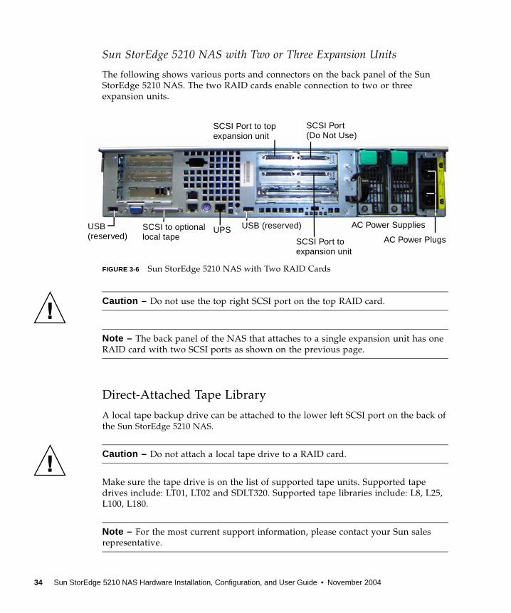
Sun StorEdge 5210 NAS with Two or Three Expansion Units
The following shows various ports and connectors on the back panel of the Sun StorEdge 5210 NAS. The two RAID cards enable connection to two or three expansion units.
FIGURE 3-6 Sun StorEdge 5210 NAS with Two RAID Cards
Caution – Do not use the top right SCSI port on the top RAID card.
Note – The back panel of the NAS that attaches to a single expansion unit has one RAID card with two SCSI ports as shown on the previous page.
Direct-Attached Tape Library
A local tape backup drive can be attached to the lower left SCSI port on the back of the Sun StorEdge 5210 NAS.
Caution – Do not attach a local tape drive to a RAID card.
Make sure the tape drive is on the list of supported tape units. Supported tape drives include: LT01, LT02 and SDLT320. Supported tape libraries include: L8, L25, L100, L180.
Note – For the most current support information, please contact your Sun sales representative.
AC Power Supplies
SCSI Port to top
USB (reserved)
AC Power Plugs
USB UPS(reserved)
expansion unitSCSI Port (Do Not Use)
SCSI to optionallocal tape SCSI Port to
expansion unit
34 Sun StorEdge 5210 NAS Hardware Installation, Configuration, and User Guide • November 2004

The SCSI ID of the tape library must be lower than the tape drive. For example, set the library ID to 0 and the drive ID to a non-conflicting value such as 5.
For details about the tape drive system you are using, refer to the documentation that came with the system.
Enclosure Cover
Caution – Only a qualified service technician should remove the Sun StorEdge 5210 NAS to access any of the components inside the server. Always properly replace the cover prior to powering on the system. Failure to replace the cover properly can seriously damage internal components.
VGA Port
Do not use the VGA port at the rear panel of the Sun StorEdge 5210 NAS. This connector is reserved for Sun Microsystems Technical Support staff and is used to diagnose the file server. For normal operation, use either the Web Administrator GUI or Telnet (see the software user guide).
FIGURE 3-7 Sun StorEdge 5210 NAS VGA Port
VGA Port
Chapter 3 Using the Sun StorEdge 5210 NAS 35

Expansion Unit ComponentsExpansion units allow you to extend the storage capabilities of your Sun StorEdge 5210 NAS server with a total available capacity of 1.3 TB per expansion unit.
FIGURE 3-8 Expansion Unit with Front Cover Removed
Expansion Unit Drive ShuttlesEach expansion unit contains up to 12 hot-swappable hard drives at the front panel. Each drive has a capacity of 133 GB for a total available capacity of 1.3 TB per expansion unit, with one drive used for parity and one hot spare drive.
Each drive is encased in its own drive shuttle. These drive shuttles can be individually replaced without shutting down the expansion unit or the Sun StorEdge 5210 NAS server.
When replacing a failed drive, use the Web Administrator to add it as a hot spare.
Caution – Hot-swap only one drive shuttle at a time! Confirm that the RAID subsystem has completed any necessary rebuild before removing another drive shuttle.
Caution – Do not update system software or RAID firmware when the RAID subsystem is in critical state or is creating newor rebuilding an existing volume.
36 Sun StorEdge 5210 NAS Hardware Installation, Configuration, and User Guide • November 2004
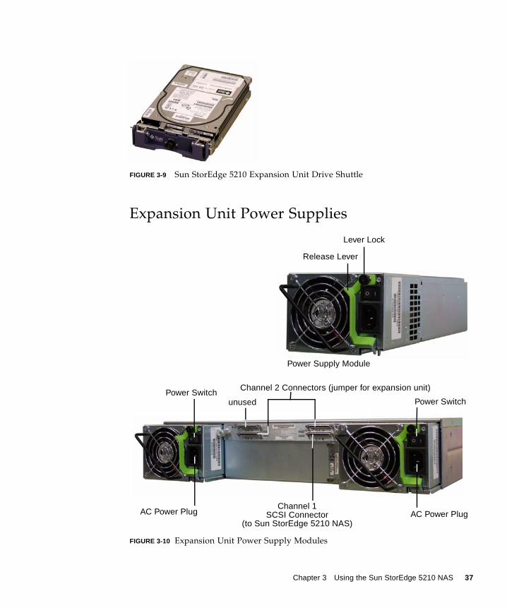
FIGURE 3-9 Sun StorEdge 5210 Expansion Unit Drive Shuttle
Expansion Unit Power Supplies
FIGURE 3-10 Expansion Unit Power Supply Modules
Release Lever
Lever Lock
Power Supply Module
Power SwitchPower Switch
AC Power Plug AC Power PlugChannel 1
Channel 2 Connectors (jumper for expansion unit)
SCSI Connector(to Sun StorEdge 5210 NAS)
unused
Chapter 3 Using the Sun StorEdge 5210 NAS 37

38 Sun StorEdge 5210 NAS Hardware Installation, Configuration, and User Guide • November 2004

APPENDIX
Specifications
This appendix contains information about the environmental and physical characteristics as well as the power requirements of your Sun StorEdge 5210 NAS and expansion unit systems.
Sun StorEdge 5210 NAS and Expansion Unit Technical Specifications
1. Power Specification
1.1. Voltage · 100-120 V ~ or 200-240 V
1.2. Frequency · 50/60 Hz ±5%Hz
1.3. AC Current Input (typical)• CPU Head · 5.2A (115 V~), or 2.6 A (230 V~)• Expansion unit · 6.0A (115 V~), or 3.0A (230 V~)
1.4 Power Consumption• CPU HEAD · 568 VA (from AC source), 426 W (from power
supply) TypicalPower Availability · 500W maximum (from power supply)
• Expansion unit · 532 VA, 400 W (typical unit)· 21 W (146 GB drives)
Power Availability · 500 W
1.5 Power Cord · SJT or SVT 18 SWG min, 3 conductor, w/250V, 10A plug/socket
Socket · IEC 320, 250V, 10A
39

1.6 Head Dissipation (BTU/hr)• CPU Head · 1448 BTU/hr (typical)• Expansion unit · 1360 BTU/hr (typical)• Hard Drive (146 GB) · 119 BTU/hr (typical)
2. Physical Characteristics
2.1. CPU Head• Dimension (HxWxD) · 89 mm x 430 mm x 648 mm (3.5 in x 16.93 in x
25.51 in)• Weight · 34.8 kg (76.6 lbs)• Rack Height · 1U
2.2 Storage Module• Dimension (HxWxD) · 134mm x 446mm x 510mm (5.25in x 17.5in x 20.1
in)• Weight · 1.25kg (2.75lb) per drive w/shuttle• Rack Height · 1.5U
3. Environmental Specifications
3.1. Temperature• CPU Head
Operating · +10°C to +35°C (+50°F to +95°F)Non-operating/storage · -20°C to +60°C (-4°F to +140°F)
• Expansion unitOperating · +10°C to +40°C (+50°F to +104°F)Non-operating/storage · 0°C to +50°C (+32°F to +122°F)
3.2. Humidity• CPU Head
Operating · 20% to 80%, non-condensingNon-operating · 10% to 90%, non-condensing
• Expansion unitOperating · 20% to 80%, non-condensingNon-operating · 8% to 80%, non-condensing
40 Sun StorEdge 5210 NAS Hardware Installation, Configuration, and User Guide • November 2004

Glossary
AC AC stands for alternating current. AC power is supplied to the computer through an electrical outlet.
AWG American Wire Gauge: used to measure thickness of wire.
Configuration The manner in which the software and hardware of an information processing system are organized and interconnected. (2) The physical and logical arrangement of programs and devices that make up a data processing system. (3) The devices and programs that make up a system, subsystem or network.
DC DC stands for directional current. DC power is typically supplied through a DC adapter or battery.
Driver A software program that enables a computer to communicate with a peripheral device. Examples include Procom Technology’s SCSI driver, a CD–ROM driver and printer drivers.
EISA Extended Industry Standard Architecture. EISA is a bus standard that maintains compatibility with the earlier Industry Standard Architecture (ISA). EISA has a 32-bit data path and uses connectors that can accept ISA cards. See also ISA.
Failure A detectable physical change in hardware or software that disrupts normal (proper) operation. A failure is repaired by the replacement of a physical component or software.
Fast Ethernet (Single and Multi-Port) A high-speed version of Ethernet transmitting data at 100 Mbps. Fast Ethernet networks use the same media access control method that 10Base-T Ethernet networks use, but achieve 10 times the data transmission speed. Fast Ethernet use twisted-pair wiring or fiber optic cable.
Flash Memory A special type of read only memory (ROM) that enables users to upgrade the information contained in the memory chips.
Gigabyte (GB) A unit of information equal to 1,024 megabytes.
41

Gigabit Ethernet An Ethernet technology that enables data transfer rates of up to 1 Gbps using optical fiber cable.
Hot Replacement of Components (Hot Swap) The ability to replace a failed component without interruption of system service.
Interface Cable A cable designed to connect a computer to a peripheral device, or a peripheral device to another peripheral device, allowing each device to communicate with one another.
Kilobyte (KB) A unit of information equal to 1,024 bytes.
LCD Liquid Crystal Display. A low-power display technology that uses rod-shaped crystal molecules that change their orientation when an electrical current flows through them.
LED Light Emitting Diode. A semiconductor device that converts electrical energy into light.
Megabyte (MB) A unit of information equivalent to 1,048,576 bytes or 1,024 kilobytes. Most uses of megabytes, however, refer to exactly 1 million bytes.
Megahertz (MHz) A measure of frequency equivalent to 1 million cycles per second.
Motherboard A large circuit board that contains the computer’s central processing unit (CPU), microprocessor support chips, random-access memory (RAM) and expansion slots.
MTBF Mean Time Between Failures. The estimated time a device operates before a failure occurs.
NAS Network Attached Storage. A storage appliance that connects directly to the network. Does not usually perform network directory services or function as an application server; instead, augments storage capacities. Quick and easy to set up, NAS appliances also typically provide cross-platform file sharing.
NIC Network Interface Card. An adapter that lets you connect a network cable to a microcomputer. The card includes encoding and decoding circuitry and a receptacle for a network cable connection.
RAID Redundant Array of Independent Disks. A group of hard disks under the control of array management software that work together to improve performance and decrease the odds of losing data to mechanical or electronic failure by using techniques such as data striping.
RAID Level 5 The most commonly used RAID implementation. RAID level 5 uses a sector-based striping scheme like RAID-level 4, but it does not require a special data-checking disk since it distributes that function across the entire array.
RAM Random Access Memory. Semiconductor-based memory that can be read and written by the microprocessor or other hardware devices. Generally understood to refer to volatile memory, which can be written as well as read.
42 Sun StorEdge 5210 NAS Hardware Installation, Configuration, and User Guide • November 2004

SCSI Small Computer Systems Interface. It is a standard interface for PCs that allows you to connect up to seven peripheral devices (like CD–ROM drives).
SCSI Bus A pathway between SCSI hardware devices. In the case of SCSI devices, the bus usually consists of a circuit board, or card, in a computer or other device and a CD–ROM drive, tape backup or the like.
SCSI Host Adapter Printed circuit board (also called an interface card) that enables the computer to use a peripheral device for which it does not already have the necessary connections or circuit boards.
SCSI ID Priority number (address) of a SCSI device in a SCSI device chain. Only one device at time can transmit through a SCSI connection (port), and priority is given to the device with the highest address. SCSI IDs range from 0 to 7, and each SCSI device must be given a unique and unused SCSI ID.
SMB Network protocol for exchanging files typically used by Windows for Workgroups and OS/2.
Striping A RAID-based method for data storage in which a single drive is designated to store error-correction (or parity) data, with the remaining drives in an array used to record sequential, smaller-sized portions of data.
Termination The electrical connection at each end of the SCSI bus, composed of a set of resistors on internal SCSI devices or an active or passive SCSI terminator block on external SCSI devices.
Glossary 43

44 Sun StorEdge 5210 NAS Hardware Installation, Configuration, and User Guide • November 2004

Index
Bback panel components 33, 34
Ccard
network interface 29clients 2components
back panel 33, 34external 30internal 27
connectionsnetwork 3power 14
conventions 4
Ddrive shuttle 36
Eelectrical grounding 13expansion unit 36
drive shuttle 36hard drives 36
external components 30
Ffront panel
switches 31
Ggrounding requirements 13
Hhard drives 36
Iindicators
LED status 32interface
user 31internal components 27
LLED status indicators 32
45

Nnetwork
connections 3interface card 29
Ppanel
back, components 33, 34front, switches 31
portVGA 35
powerconnections 14
power supply 37power switches 31protocols 2
Rrequirements
grounding 13
Ssecurity 2shuttle
drive 36status
indicators, LED 32status LED indicator 32Sun StorEdge 5210 NAS
back panel components 33, 34expansion unit 36external components 30LED status indicators 32power switches 31user interface 31VGA port 35
supported clients 2switches
front panel 31power 31
system status 32
Ttechnical support 5
Uuser interface 31
VVGA port 35
46 Sun StorEdge 5210 NAS Hardware Installation, Configuration, and User Guide • November 2004