swfwmd main grade road bridge no. 3 existing steel ... · 1.2 submittals: provide the following...
TRANSCRIPT

Greenman-Pedersen, Inc. 1000 N. Ashley Drive, Suite 100 Tampa, FL 33602 p 813-632-7676
An Equal Opportunity Employer
SWFWMD Main Grade Road Bridge No. 3
Existing Steel Cleaning and Painting
1 GENERAL.
1.1 Scope of Work. Clean and paint steel with a four coat organic zinc rich epoxy primer based system in
accordance with the requirements of this specification.
1.1.1 Remove the bridge deck before initiating any cleaning and painting operations. Replace the
bridge deck after cleaning and painting in accordance with the contract documents.
1.1.2 During the following operations erect and maintain containment that meets the listed
requirements of SSPC Guide No. 6, "Guide for Containing Surface Debris Generated During Paint
Removal Operations”:
1.1.2.1 Pressurized Water Washing: Class 2W
1.1.2.2 Abrasive Blast Cleaning: Class 1A
1.1.2.3 Power Tool Cleaning: Class 3P
1.1.2.4 Paint Application: Isolate the work area with tarpaulins or other materials to prevent
paint from leaving the work area.
Ensure the lighting inside the containment is in accordance with SSPC Guide No. 12, “Guide for
Illumination of Industrial Painting Projects. Provide lighting to a minimum of 20 foot-candles
for general, 50 foot-candles for work, and 200 foot-candles for inspection.
1.2 Submittals: Provide the following submittals and receive acceptance by the District prior to performing
any work associated with cleaning and painting. Maintain certifications for the duration of the Contract.
If a certification expires, is suspended, placed on probation or otherwise changes, do not perform any
work until the certifications is fully valid. Notify the District immediately of any change in certification
status.
1.2.1 Corporate and Site-specific QC/QA Plan: At a minimum, the plan must include:
1.2.1.1 Contractor’s Organizational Chart clearly identifying line of authority and each
individual’s project responsibility.
1.2.1.2 Qualifications, Certifications, Training and Experience Records of the Contractor and
project personnel.
1.2.1.3 Receipt, Distribution and Revisions of Project Documents.
1.2.1.4 Quality Control Inspection Standards and Equipment.
1.2.1.5 Inspection of Cleaning and Painting Equipment and Calibration of Inspection
Instruments.
1.2.1.6 Standards, Equipment and Procedures.
1.2.1.7 Frequency, type, passing criterion for all QC Tests and Reports.

1.2.1.8 Repair Procedures.
1.2.1.9 Materials Control, Handling and Storage.
1.2.1.10 Adjacent Area Protection Plan.
1.2.1.11 Sample forms and reports.
1.2.2 Corporate and Site Specific Environmental, Health and Safety (EH&S) Plan: at minimum the
plan must include:
1.2.2.1 Soil Protection and Testing
1.2.2.1.1 Soil Contamination Reporting and Clean-up Procedure
1.2.2.1.2 Pre and Post Project Soil Sampling Plan – number and location of samples.
1.2.2.1.3 Certifications of the proposed laboratory.
1.2.2.2 Waste Management
1.2.2.2.1 Waste Handling, Storage, Transportation, Treatment and Disposal
Procedures.
1.2.2.2.2 Laboratory Analysis and Laboratory Certification
1.2.2.2.3 Location of Waste Storage Site
1.2.2.3 Ambient Air Monitoring
1.2.2.3.1 Type, number and location of monitors.
1.2.2.3.2 Monitoring Procedures
1.2.2.3.3 Ambient Air Monitoring Sample Testing Laboratory Certification
1.2.2.4 Visible Emissions Monitoring
1.2.2.4.1 Method
1.2.2.4.2 Reports
1.2.2.4.3 Corrective Actions
1.2.2.5 Regulated Area
1.2.2.5.1 Personal Air Monitoring Plan
1.2.2.5.2 Personal Air Monitoring Sample Testing Laboratory Certification
1.2.2.5.3 Method of Demarcating Regulated Area
1.2.2.6 Containment Plan
1.2.2.6.1 Containment Drawings and Calculations
1.2.2.6.2 Dust Collection and Containment Ventilation Plan and Calculations
1.2.2.6.3 Containment Illumination Plan
1.2.2.7 Emergency Contingency Plans
1.2.2.7.1 Hurricane Evacuation Route

1.2.2.7.2 Location of nearest Emergency Medical Treatment Centers
1.2.2.7.3 First Aid Procedures
1.2.2.7.4 Spills or Leaks Plan
1.2.2.7.5 Fire or Explosion Prevention and Contingency Plans
1.2.2.8 Employee Training to include SSPC C-3 and C-5
1.2.2.9 Site Clean-up and De-mobilization Plan
1.2.2.10 Employee Medical Surveillance Plan
1.2.2.11 Personal Protective Equipment (PPE)
1.2.2.11.1 Respirator Program
1.2.2.11.2 Eye and Hearing Protection Plan
1.2.2.12 Working over Water Safety Plan
1.2.3 Materials: Product Data Sheets (PDS) and Safety Data Sheets (SDS) for all materials to be
brought onto the project site.
1.3 Surfaces Not to be Coated. Surfaces specified not to be coated that are adjacent or in close proximity
to surfaces to be coated shall be protected with suitable masking during the coatings application. The
masked surfaces shall form neat horizontal and vertical lines and shall conform to the dimensions
specified not to be coated. Coatings applied to areas not to be coated shall be removed. Removal of
said coatings and replacement/repair of surfaces damaged during removal will be performed by the
Contractor at no cost to the District.
2. MATERIALS.
2.1 Coatings: Use a coating system consisting of a full coat of organic zinc rich epoxy primer, a spot coat of
100% solids epoxy penetrant sealer, one stripe coat of aluminum epoxy mastic, one full coat of epoxy
intermediate paint, one stripe coat of aluminum epoxy mastic, a finish coat of aliphatic polyurethane
and a polyurethane clear coat listed on the Florida DOT’s Approved Product List (APL) and approved by
the District. The polyurethane clear coat must contain a dissipating colorant which facilitates inspection.
The dissipating colorant must be visible for a minimum of 12 hours after application and shall
completely dissipate within 96 hours after application.
2.2 Thinners, Solvents and Cleaners: Use thinners, solvents and cleaners listed on the coating
manufacturer’s PDS.
2.3 Caulking: Use caulks that are paintable, compatible with the coating system and recommended by the
coating manufacturer as part of the coating system. Provide a letter signed by a technical representative
of the coating manufacturer confirming the proposed caulk meets each requirement.
2.4 Soluble Salts Test Kit: Use a soluble salts test kit in accordance with SSPC Guide No. 15, “Field Methods
for Extraction and Analysis of Soluble Salts on Steel and Other Nonporous Substrates”, utilizing a latex
sleeve or patch/cell retrieval method. Ensure the test sleeve or cell creates a sealed, encapsulated
environment during ion extraction and is suitable for testing all structural steel surfaces. As an
alternative, electronic conductivity meters approved for use by the District may be used.
2.5 Pressurized Washing Water: Provide and use water of sufficient purity and quality that does not
prevent the surface from being cleaned to meet the cleanliness and soluble salt requirements.

2.6 Abrasives: Use properly sized abrasives to achieve the required cleanliness and anchor profile. Use
abrasives meeting the requirements of SSPC-AB 1, Mineral and Slag Abrasives, SSPC-AB 2, Cleanliness
of Recycled Ferrous Metallic Abrasives, or SSPC-AB 3, Newly Manufactured or Re-Manufactured Steel
Abrasive and do not introduce any contamination that interferes with the coating application and
performance. Provide certification to the District the abrasives used meet the requirements of this
specification and do not contain any chlorides and other salts. For mineral and slag abrasives, verify
compliance with the conductivity and cleanliness requirements of SSPC-AB1. For recycled abrasives,
verify compliance with conductivity and cleanliness requirements of SSPC-AB 2 after each recycling or
more frequently if required by the District. Select a sample from each recycling machine in use and
conduct the water-soluble contaminant and oil content tests outlined in SSPC-AB 2 at least one time
each week or more frequently if directed by the District. Conduct the non-abrasive residue and lead
content tests as directed by the District. If test results do not meet requirements, notify the District
immediately, remove and replace the abrasive, clean the recycling equipment, and conduct tests each
day to confirm the equipment is functioning properly. Return to the weekly testing interval as directed
by the District.
2.7 Storage: Store materials in conformance with the manufacturer’s recommendations. Maintain a
continuously monitoring and recording thermometer in the materials storage area.
3. EQUIPMENT.
3.1 Compressed Air: Use a compressed air system capable of delivering clean, dry, continuous nozzle
pressure to achieve the required surface cleanliness and profile or spray pattern. The system must
comply with the instructions and recommendations of the manufacturer of the abrasive blasting system
or coating application system.
3.2 Abrasive Blasting System: Design the blasting system to produce the specified cleanliness and profile.
3.3 Coating Application System: Use the coating application equipment approved by and in accordance
with the coating manufacturer’s technical data requirements.
4. QUALITY CONTROL.
4.1 QC Personnel: All personnel performing QC functions must employed by the contractor performing
cleaning and painting operations. QC personnel are not permitted to supervise or perform cleaning
and coating operations.
4.1.1 QC Specialist: The QC Specialist is responsible for the quality control of all cleaning and painting
operations; and supervision of QC Inspectors. A QC Specialist, at a minimum, must be NACE
International (NACE) Coatings Inspector Program (CIP) Level III certified. The QC Specialist shall
have a minimum of three years of experience in the inspection of cleaning and painting
structural steel and a minimum of five years of experience in the field of corrosion control using
coatings on steel structures.
4.1.2 QC Inspectors: QC Inspectors, at a minimum, must be certified NACE International (NACE) CIP
Coating Inspector Level I or a Society for Protective Coatings (SSPC) Level 1 Bridge Coating
Inspector; have at least 1 year of experience in the inspection of cleaning and painting of
structural steel and report directly to a QC Specialist who meets the requirements of 4.1.1. A
QC Inspector must be on site at all times when work is performed.
4.2 Inspection: Ensure all inspection equipment is maintained in accordance with the manufacturer’s
instructions, calibrated, and in good working condition. Ensure all activities are observed and approved
by a quality control coatings inspector meeting the requirements of this specification. Maintain daily
inspection reports at the job site for review by the District. Provide all daily inspection reports upon

completion of the project to the District or more frequently as requested by the District. The QC
Specialist shall also provide a final report to the District describing the general characteristics of the
work for the project including all QC test data. Report all collected data in typed form. Submit reports
by electronic media acceptable to the District along with four bound hard copies. The following list
defines the minimum inspection hold points. If at any hold point the work or conditions do not meet
contract requirements, the Contractor must cease work immediately, identify the source of non-
conformity, propose corrective action and proceed only after approval of the District or their field
representative.
4.2.1 Ambient conditions
4.2.2 Pre-cleaning
4.2.3 Surface Preparation
4.2.4 100% Solids Epoxy Penetrant/Sealer Application
4.2.5 Coatings Mixing
4.2.6 Coatings Application
4.2.7 DFT of each coat
4.2.8 Visual Application Defects
4.2.9 Cleanliness between Coats
4.2.10 Recoat Windows
During Quality Control inspections, document the location and type of each defect. Notify the District
of the readiness to proceed with District QA inspection. Repair with approved procedure, any defects
identified. Repeat process until prepared for 90% inspection. Request 90% inspection by the District a
minimum of seven days prior to requested inspection date. The size of the area(s) for 90% inspection
will be at the discretion of the District.
5. QUALIFICATIONS.
5.1 Contractor: The Contractor must be SSPC-QP1 and SSPC-QP2 certified. Contractor’s superintendent
supervising or executing the cleaning and painting work shall have a certified experience record
indicating at least three years’ experience on similar type work.
6. SURFACE PREPARATION.
6.1 General: Clean, wash, remove soluble salts, and dry abrasive blast or hand and power tool clean (if
accepted by the District) to remove all corrosion in the intended locations. Abrasive blast clean all
surfaces to be painted to meet the requirements of NACE No. 2 / SSPC SP-10, “Near White Blast”. Notify
the District immediately when any structural steel appears to be defective. Ensure all surfaces to be
coated are clean, dry, and free from oil, grease, dirt, dust, soluble salts, corrosion, caulking, weld
spatter, mill scale and any other surface contaminants. Sequence the surface preparations and coating
operations so that freshly applied coatings will not be contaminated by dust or foreign matter. Protect
all equipment and adjacent surfaces not to be coated from surface preparation operations. In the event
that any rusting or contamination occurs after the completion of the surface preparation, prepare the
surfaces again to the initial requirements. Perform surface preparation work only when the
temperature of the steel surface is at least 5oF above the dew point temperature.
6.2 Mechanical Removal of Surface Defects: Break all corners resulting from sawing, burning, or shearing.

In areas where burning has been used, remove the flame hardened surface of the steel to the extent
necessary the required surface profile can be achieved by subsequent dry abrasive blasting. Remove all
weld slag and weld spatter. Conduct all of this work in accordance with ASHTO/NSBA Steel Bridge
Collaboration S 8.1. In addition, remove all pack rust prior to solvent cleaning.
6.3 Cleaning: Clean all steel surfaces in accordance with the requirements of SSPC-SP 1, “Solvent Cleaning”.
6.4 Washing: Clean all surfaces to meet the requirements of SSPC-SP1 with pressurized water with a
minimum of 3,500 psi.
6.5 Soluble Salts Detection and Removal: Use SSPC Guide No. 15, latex sleeve or patch/cell retrieval
methods to determine the chloride, sulfate and nitrate concentrations on all steel surfaces using soluble
salts test kits meeting the requirements of 2.4. Measure the concentration levels using the appropriate
method described in SSPC Guide No. 15. Perform the tests after washing and after each applied coat of
the coating system. Ensure the non-visible surface contaminant concentrations on blast-cleaned
surfaces do not exceed 7 g/gm2 for chlorides, 10 g/cm2 for soluble ferrous iron, 17 g/m2 for sulfates and
10 g/cm2 for nitrates. When using electronic conductivity meters, use meters meeting the requirements
of 2.4 and measure the surface conductivity as prescribed by the manufacturer. The instrument shall
be properly calibrated and maintained according to the manufacturer’s recommendations. Ensure the
surface conductivity does not exceed 70 micro-Siemens per centimeter squared. For either contaminant
assessment method (salt test kits or conductivity meter) test five random locations in the first 1000
square feet and one random location for each subsequent 1000 square feet. When any concentration
or conductivity measurement exceeds the levels given above, rewash the entire surface area and retest
all potentially contaminated steel to the satisfaction of the District. If additional washing does not
reduce the concentration to the acceptable level, a surface treatment or water additive may be used.
Use a surface treatment or water additive that is approved by the coating system supplier and the
District.
6.6 Dry Abrasive Blast Cleaning: Prepare steel by dry abrasive blast cleaning to to meet the requirements
of NACE No. 2 / SSPC-SP 10. Use SSPC-VIS 1, “Guide and Reference Photographs for Steel Surfaces
Prepare by Dry Abrasive Blasting” as an aid in establishing cleanliness. After abrasive blast cleaning,
ensure the surface profile meets the strictest requirements of the primer coating manufacturer’s PDS.
Protect all areas adjacent to abrasive blast cleaning. Repair any damage to adjacent areas at no cost to
the District. The repair procedure must be submitted to the District for acceptance prior to any
remediation. Ensure the abrasive blast cleaning does not produce holes, cause distortion, or cause
thinning of the substrate. Determine the surface profile in accordance with ASTM D4417, “Standard
Test Methods for Field Measurement of Surface Profile of Blast Cleaned Steel,” Method C. Obtain
profile depth measurements at a minimum of every 550 ft2.
6.7 Hand and Power Tool Cleaning: Prepare steel by power and hand tool cleaning as defined in SSPC-SP
11, SSPC-SP 3, and SSPC-SP 2 as approved by the District. Use SSPC VIS 3 as an aid in establishing
cleanliness.
7. APPLICATION.
7.1 General: Apply a complete coating system to all structural steel surfaces except surfaces indicated in
1.3. Prior to the application of any coating, inspect the substrate (or previous coat) for contamination
and defects, and prepare the surface in accordance with this specification before application of the
primer and subsequent coats. Apply each coat including a stripe coat in a color that contrasts with the
substrate or preceding coat. The color of the finish coat shall meet FED-STD-595C, Color No. 20091. The
sequence of painting shall be as follows: Use the following sequence: full organic zinc r rich primer
coat, 100% solids epoxy penetrant sealer spot coat to surfaces inaccessible to SSPC-SP 10 abrasive

blast cleaning as deemed by the District, aluminum epoxy mastic stripe coat, full epoxy intermediate
coat, aluminum epoxy mastic stripe coat, full aliphatic polyurethane finish coat, and then polyurethane
clear coat.
7.2 Weather and Temperature Limitations: Do not spray coatings when the measured wind speed in the
immediate coating area is above 15 miles per hour. Do not apply coatings when contamination from
rainfall is imminent or when the ambient air temperature, relative humidity, dew point temperature,
or temperature of the steel is outside limits of the coating manufacturer’s PDS. Do not apply coatings
when substrate temperature is less than 5 degrees F above dew point.
7.3 Sealing Using Caulk: Using caulk meeting the requirements of this specification, completely seal the
perimeter of all faying surfaces, cracks and crevices, joints, and skip-welded joints open less than 1/2
inch. Apply the caulk following the caulk manufacturer’s recommendations. Ensure the caulk bead has
a smooth and uniform finish and is cured according to the caulk manufacturer’s recommendation prior
to the application of subsequent coatings. For areas to be caulked, apply caulk after the application of
the second aluminum epoxy mastic stripe coat intermediate coat and before application of the aliphatic
polyurethane finish coat.
7.4 Mixing and Thinning: Mix all coatings in accordance with the manufacturer’s PDS. Only mix complete
kits. Do not add an amount of thinner which result in the coating exceeding VOC regulations. Perform
all mixing operations over an impervious surface with provisions to prevent runoff of any spilled
material.
7.5 Application Methods: Use coating application equipment and apply coatings per the coating
manufacturer’s PDS. Application with brushes may be permitted for minor touchup of spray
applications, stripe coats, or when otherwise approved by the District. Apply organic zinc rich epoxy
primer as soon as possible no more than eight hours after dry abrasive blast cleaning. Adjust spray
equipment to produce an even, wet coat with minimum overspray. Apply coatings in even, parallel
passes, overlapping 50 percent. Agitate coatings during application as required by the coating
manufacturer’s PDS.
7.5.1 Stripe Coating: Use an aluminum epoxy mastic that is at least 80% solids by volume. Apply
stripe coats by brush only. Apply the stripe coat per the manufacturers published PDS but no
less than 3 mils DFT. Apply stripe coats to achieve complete coverage on welds, corners,
crevices, sharp edges, bolts, nuts, rivets, and rough or pitted surfaces. A stripe coat of
translucent coatings is not required. Do apply subsequent coats until the previous stripe coat
has cured per the manufacturer’s PDS for recoating.
7.6 Thickness of Coats: After application of each coat, thoroughly inspect the surfaces and measure the
DFT in accordance with SSPC-PA 2, “Procedure for Determining Conformance to Dry Coating Thickness
Requirements”, Table 1, Restriction Level 2 (organic zinc rich primer) or Restriction Level 3 (all other
polymeric coatings), with a Type 2 magnetic coating thickness gage. When the DFT is deficient or
excessive, correct in accordance with the coating manufacturer’s recommendations and re-measure
the area.
7.7 Coating Drying, and Curing: Apply coatings within the time specified by the coating manufacturer’s PDS
for drying and recoating. Before handling, test for cure in accordance with the manufacturer’s
recommended method. Meet the requirements of ASTM D5402, “Standard Practice for Assessing the
Solvent Resistance of Organic Coatings Using Solvent Rubs,” for organic zinc primers when the
manufacturer’s technical data sheet does not state a specified cure test. Obtain the acceptance criteria
from the coating manufacturer and report the results to the District.
7.8 Coating Finish: Apply each coat free of runs, sags, blisters, bubbles, and mud cracking; variations in

color, gloss, or texture; holidays; excessive film buildup; foreign contaminants; orange peeling;
overspray and other defects.
7.9 Touchup and Repair: Submit a touchup and repair procedure for approval by the District.
8. ENVIRONMENTAL, HEALTH AND SAFETY REQUIREMENTS. Isolate the work areas with containment devices,
canvasses, tarpaulins or screens during all surface preparation and coating application operations. Dispose of
all debris and waste products generated in accordance with all Federal, State and Local regulations.
8.1 General: Establish plans and programs to protect the environment, public, contractor employees,
other workers, and property from overspray, exposure to toxic heavy metals and the release and
emission of hazardous materials and nuisance dusts. Include in such plans and programs a procedure
for the receipt, processing, evaluation and timely written response for claims by the public for damage
resulting from the foregoing work. Provide the District with copies of any written response which denies
such damage claims. Conduct all coating application and removal operations in compliance with EPA,
OSHA, and other applicable Federal, State and local regulations. Provide a contingency plan for the
remediation of water and land in the event of contamination by solid or liquid paint and contaminated
water.
8.2 Environmental Protection: Comply with all applicable Federal, State, and Local rules and regulations.
Prepare and submit to the District, plans and programs for the protection of the environment and public
based on the applicable EPA requirements, the requirements of this Section, and the Contract
Documents. Include plans and programs for the protection of the air, soil/ground, and water.
8.2.1 Pollution Control: As part of the EH&S plan submit a written pollution control and monitoring
plan that the clearly describes the means for complying with all Local, State and Federal
regulations including pollution control provisions specified herein. The written plan must be in
accordance with SSPC Project Design: Industrial Lead Paint Removal Handbook, Volume II,
Phase 6, Environmental Monitoring, and specifically include, but not be limited to, providing a
scaled map of the work site layout showing the proposed number and location of soil sampling,
Total Suspended Particulate (TSP) monitoring sites, waste storage areas, staging areas,
temporary waste storage areas, and ambient air and personnel sampling frequency.
Immediately cease all operations in the event a violation of any environmental regulation or a
failure to properly execute any pollution control provisions occurs. Resume operations after
written proposed corrective procedures have been submitted to and approved by the District
and implemented.
8.2.2 Permits: Submit all required permits from all applicable regulatory agencies to the District prior
to the commencement of any work. Seek permit determination from these regulatory agencies
to avoid any potential permit non-compliance issues during work activities. The Contractor is
responsible for all liability resulting from non-compliance with pertinent rules and regulations
including permit requirements.
8.2.3 Ambient Air Quality Compliance and Protection of the Air:
8.2.3.1 Visible Emissions: Assess the visible emissions using EPA Method 22, Timing of
Emissions as defined by 40 CFR 60, Appendix A, Standards of Performance for New
Stationary Sources. During abrasive blasting, do not allow visible emissions from a
containment to exceed a random cumulative duration of more than one percent of
the workday (SSPC Guide No. 6, Level 1 Emissions). During pressurized water cleaning,
do not allow visible emissions from a containment to exceed a random cumulative
duration of more than ten percent of the workday (SSPC Guide No. 6, Level 3
Emissions).

8.2.3.2 Total Suspended Particulate (TSP) Matter: Control emissions from the containment
area to prevent exceeding the TSP Lead of 1.5 µg/m3 over a 90 day period, or the daily
and adjusted daily allowances of SSPC-TU 7, “Conducting Ambient Air, Soil, and
Water Sampling During Surface Preparation and Paint Disturbance Activities.”
Conduct TSP Lead monitoring in accordance with 40 CFR 50, Appendix B, Reference
Method for Determination of TSP Matter in the Atmosphere (high volume sampler
required), and 40 CFR 50, Appendix G, Reference Method for Determination of TSP
Matter Collected from Ambient Air. Position the TSP monitoring equipment in general
accordance with 40 CFR 58, Ambient Air Quality Surveillance. Perform TSP Lead
background monitoring for a period of 3 days prior to the beginning of abrasive blast
cleaning operations. Submit the results from background monitoring and the first
week of monitoring during abrasive blast cleaning to the District for review within 5
calendar days after the first week of work. Continue monitoring unless otherwise
directed by the District.
8.2.3.3 Regulated Area: Establish a regulated area around the work site to prohibit
unauthorized persons from areas where exposure to hazardous airborne metals may
exceed the following action levels:
Airborne Metals Action Level
Lead 30 µg/m3
Cadmium 2.5 µg/m3
Arsenic 5.0 µg/m3
Hexavalent Chromium (Cr6+) 2.5 µg/m3
Conduct monitoring in accordance with the National Institute for Occupational Safety
and Health (NIOSH) procedures upon initiation of dust producing operations and
submit the test results to the District within 72 hours of sampling. Report sample
results as eight-hour Time Weighted Averages (TWA). Reestablish the regulated area
and perform additional sampling when the results exceed the action levels or when
directed by the District. Document all pertinent data in a field logbook. Position air-
sampling pumps around the project perimeter where the public or personnel can
approach the work area. Place sampler inlets at breathing height. Clearly mark the
regulated area by the use of warning signs, rope, barrier tape, or temporary
construction fencing.
8.2.4 Soil/Ground Quality: Inspect the ground beneath and in proximity to the structure in the
presence of the District for visible paint chips to establish an initial job site cleanliness standard.
Test soil samples prior to the beginning of operations and after project completion for heavy
metals. Document the number and specific locations where the initial samples are taken as
outlined in the SSPC Project Design- Industrial Lead Paint Removal Handbook, Volume 2 to
ensure the post samples are collected from the same locations. Submit all samples to the
District for review. If the project activities increase the heavy metal content in soil to more than
20% above the pre-job geometric mean or 100% at any one location, return the site to the pre-
job levels. Conduct additional soil testing as necessary to determine the extent of
contamination. Take one sample north, south, east, and west (where soil is present) of the
structure. Take one additional sample for every 14 feet in length. In addition, submit a pre- and
post- soil sampling plan for storage areas identifying the sample location, depth, analyses list,
lab certification, and turnaround time. Once approved by the District, submit sampling results
along with a scaled drawing indicating designated sample locations.
8.2.5 Water Quality: Do not release, discharge or otherwise cause hazardous materials, debris,
waste, or paint chips to enter the water. Protect against releases due to rain and methods of
surface preparation from reaching rivers, streams, lakes, storm drains, or other bodies of water.
8.3 Containment System: Submit a written containment system design plan in accordance with this section
and the contract documents which clearly describes the proposed containment system applicable to
the intended removal method and in accordance with the requirements outlined herein. Ensure the
plan includes, but is not limited to, removal method; methods for collecting debris; and containment
enclosure components. Use fire retardant materials. Provide containment drawings, calculations, and
assumptions, including ventilation criteria if applicable, signed and sealed by a Specialty Engineer.
Provide a complete structural impact analysis prepared by the Specialty Engineer to verify the existing
structure can withstand the additional dead, live and wind loads imposed by the containment system,
signed and sealed by the Specialty Engineer. Include a clear description of the ventilation system
components. Design ventilation meeting the requirements of this specification; SSPC Guide No.6; and
cross draft of 100 feet per minute and downdraft of 50-60 feet per minute.
Isolate the immediate area of the structure to ensure compliance with current and permit
requirements for air, water, soil, and pollution prevention. Protect the containment system from
vehicular and pedestrian traffic. Ensure paint, paint chips, or other debris will not fall outside of the
containment area under any circumstances. Repair any damage created by fastening, bracing, or
handling the scaffolding and staging. If a suspended platform is constructed, use rigid or flexible
materials as needed to create an air and dust impenetrable enclosure. Verify the platform and its
components are designed and constructed to support at least four times its maximum intended load
without failure, with wire cables capable of supporting at least six times their maximum intended load
without failure. Strictly comply with all applicable OSHA regulations regarding scaffolding. Prior to use,
the must verify, in the field, the containment and staging has been erected in accordance with the
signed and sealed plan. Any changes to the accepted signed, sealed and accepted plan must be made,
re-signed and re-sealed by the Specialty Engineer and submitted to the District for review and
acceptance.
8.4 Worker Protection: Comply with the requirements of OSHA 29 CFR 1926 and applicable portions of 29
CFR 1910. Include specific programs as required by 29 CFR 1926.62 (lead), 29 CFR 1926.1118 (inorganic
arsenic), 29 CFR 1926.1126 (hexavalent chromium), and 29 CFR 1926.1127 (cadmium) when these
hazardous agents are present. Implement appropriate safety procedures for all hazards on the job site
whether specifically identified herein or not.
9. WASTE HANDLING AND MANAGEMENT.
9.1 General: Prepare a waste management program plan which addresses the applicable requirements
from EPA regulations for hazardous waste management and the Contract Documents. Include
provisions for the handling and disposal of non- hazardous waste. Dispose of all waste in accordance
with all federal, state, and local laws and regulations.
9.2 Collection and Handling of Waste: Properly classify, package, and store all paint removal debris, both
solid and liquid in accordance with SSPC Guide 7, “Guide for the Disposal of Lead-Contaminated Surface
Preparation Debris, the Federal Water Pollution Control”, Act with amendments, and all other current
government regulations and guidelines. Comply with the Resource Conservation and Recovery Act to
include, at a minimum, CFR 40 260 through CFR 40 268. Prior to identification and storage, separate
solid and liquid waste, and separate individual waste streams.

9.3 Testing and Analysis: Laboratory analyses for all waste stream and environmental samples shall be
conducted by an EPA certified, independent laboratory with an approved Quality Assurance Plan.
Laboratory analyses for worker monitoring and regulated area samples shall be conducted by an
American Industrial Hygiene Association (AIHA) metals accredited laboratory. Provide a copy of all
sampling and test reports no later than 72 hours after collection of samples.
9.4 Waste Identification: Collect samples in accordance with EPA SW 846, Test Methods for Evaluating
Solid Waste - Physical/Chemical Methods. Use a random and representative sampling technique.
Collect a minimum of four representative samples of each waste stream. These waste streams include,
but are not limited to, water, paint chips, dust, and paint chips mixed with disposable abrasives and
debris. Complete the initial sampling of each waste stream immediately upon filling the first drum, but
do not allow waste to accumulate for longer than 7 days before sampling. After the representative
samples are collected, send them immediately to the EPA certified laboratory for analysis. Unless
otherwise directed by the District, required by State regulations, or required by the waste recycling or
disposal facility, once each waste stream is sampled, tested, and classified, additional sampling and
analysis are not required for subsequent shipments unless the waste stream changes. Submit samples
to an approved laboratory to be tested for arsenic, barium, cadmium, hexavalent chromium, lead,
mercury, selenium, and silver in accordance with EPA Method 3050 and Method 6010 (content) and
EPA Method 1311, Toxicity Characteristics Leaching Procedures (TCLP). Clearly label each sample with
sample number, date and time of sampling, name of collector, and location of collection. Maintain
chain of custody forms for each sample. Enter each sample on a sample analysis request form. Enter
sample numbers, type of waste, amount of each sample, distribution of samples, signature and all other
information into field logbook.
9.5 Waste Storage: Collect waste from the control devices, equipment, and all work surfaces on a daily
basis. Keep hazardous and non-hazardous waste separate. Do not mix blasting debris with any other
type of waste. Place waste in approved storage drums. Locate all hazardous waste within a regulated
area. The maximum weight for each drum, when filled, is 821 pounds. Properly seal and label all drums.
Transport waste storage drums to a secured, marked, temporary storage area. Locate the temporary
storage area on well- drained ground not susceptible to flooding or storm water run-off. Place drums
on a pallet and cover with fiber reinforced, impermeable tarpaulins. Store drums no more than two
drums wide and two drums high. Arrange drums so that labels are easily readable. Do not store waste
in the temporary storage area longer than 90 days.
9.6 Waste Disposal: Transport, treat and dispose of all hazardous and non-hazardous waste. Notify the
District a minimum of three weeks prior to the date of shipment of any waste to an off- site facility.
Provide the District with documentation that the receiving disposal facilities are properly licensed.
Provide manifests for all hazardous and non-hazardous waste shipments. Identify any waste disposal
subcontractors and provide a copy of their licensing to perform waste disposal and transport
operations. Do not use any products intended for the pre-treatment of waste.
9.7 Permits: The Contractor is responsible for all liability resulting from non-compliance with pertinent
rules and regulations including permit requirements.

Greenman-Pedersen, Inc. 1000 N. Ashley Drive, Suite 100 Tampa, FL 33602 p 813-632-7676
An Equal Opportunity Employer
SWFWMD Main Grade Road Bridge No. 3
Existing Steel Cleaning, Thermal Spray Coating and Painting
1 GENERAL.
1.1 Scope of Work. Clean, apply thermal spray coating (TSC) and paint existing steel in accordance with
the requirements of this specification and NACE 12/AWS C2.23/SSPC – CS23, “Specification for the
Application of Thermal Spray Coatings (Metallizing) of Aluminum, Zinc, and Their Alloys and Composites
for the Corrosion Protection of Steel.” Where items conflict between NACE 12/AWS C2.23/SSPC – CS23
and this specification, the requirements of this Specification shall govern.
1.1.1 Remove the bridge deck before initiating any cleaning, TSC and painting operations. Replace
the bridge deck after TSC and painting in accordance with the contract documents.
1.1.2 During the following operations erect and maintain containment that meets the listed
requirements of SSPC Guide No. 6, "Guide for Containing Surface Debris Generated During Paint
Removal Operations”:
1.1.2.1 Pressurized Water Washing: Class 2W
1.1.2.2 Abrasive Blast Cleaning: Class 1A
1.1.2.3 Power Tool Cleaning: Class 3P
1.1.2.4 TSC and Paint Application: Isolate the work area with tarpaulins or other materials to
prevent TSC and paint from leaving the work area.
Ensure the lighting inside the containment is in accordance with SSPC Guide No. 12, “Guide for
Illumination of Industrial Painting Projects. Provide lighting to a minimum of 20 foot-candles
for general, 50 foot-candles for work, and 200 foot-candles for inspection.
1.2 Submittals: Provide the following submittals and receive acceptance by the District prior to performing
any work associated with cleaning, TSC application and painting. Maintain certifications for the
duration of the Contract. If a certification expires, is suspended, placed on probation or otherwise
changes, do not perform any work until the certifications is fully valid. Notify the District immediately
of any change in certification status.
1.2.1 Corporate and Site-specific QC/QA Plan: At a minimum, the plan must include:
1.2.1.1 Contractor’s Organizational Chart clearly identifying line of authority and each
individual’s project responsibility.
1.2.1.2 Qualifications, Certifications, Training and Experience Records of the Contractor and
project personnel.
1.2.1.3 Receipt, Distribution and Revisions of Project Documents.
1.2.1.4 Quality Control Inspection Standards and Equipment.
1.2.1.5 Inspection of Cleaning and Painting Equipment and Calibration of Inspection
Instruments.
1.2.1.6 Standards, Equipment and Procedures.

1.2.1.7 Frequency, type, passing criterion for all QC Tests and Reports.
1.2.1.8 Repair Procedures.
1.2.1.9 Materials Control, Handling and Storage.
1.2.1.10 Adjacent Area Protection Plan.
1.2.1.11 TSC QA/QC Plan.
1.2.1.12 Sample forms and reports.
1.2.2 Corporate and Site Specific Environmental, Health and Safety (EH&S) Plan: at minimum the
plan must include:
1.2.2.1 Soil Protection and Testing
1.2.2.1.1 Soil Contamination Reporting and Clean-up Procedure
1.2.2.1.2 Pre and Post Project Soil Sampling Plan – number and location of samples.
1.2.2.1.3 Certifications of the proposed laboratory.
1.2.2.2 Waste Management
1.2.2.2.1 Waste Handling, Storage, Transportation, Treatment and Disposal
Procedures.
1.2.2.2.2 Laboratory Analysis and Laboratory Certification
1.2.2.2.3 Location of Waste Storage Site
1.2.2.3 Ambient Air Monitoring
1.2.2.3.1 Type, number and location of monitors.
1.2.2.3.2 Monitoring Procedures
1.2.2.3.3 Ambient Air Monitoring Sample Testing Laboratory Certification
1.2.2.4 Visible Emissions Monitoring
1.2.2.4.1 Method
1.2.2.4.2 Reports
1.2.2.4.3 Corrective Actions
1.2.2.5 Regulated Area
1.2.2.5.1 Personal Air Monitoring Plan
1.2.2.5.2 Personal Air Monitoring Sample Testing Laboratory Certification
1.2.2.5.3 Method of Demarcating Regulated Area
1.2.2.6 Containment Plan
1.2.2.6.1 Containment Drawings and Calculations
1.2.2.6.2 Dust Collection and Containment Ventilation Plan and Calculations
1.2.2.6.3 Containment Illumination Plan
1.2.2.7 Emergency Contingency Plans
1.2.2.7.1 Hurricane Evacuation Route
1.2.2.7.2 Location of nearest Emergency Medical Treatment Centers
1.2.2.7.3 First Aid Procedures
1.2.2.7.4 Spills or Leaks Plan
1.2.2.7.5 Fire or Explosion Prevention and Contingency Plans
1.2.2.8 Employee Training to include SSPC C-3 and C-5
1.2.2.9 Site Clean-up and De-mobilization Plan
1.2.2.10 Employee Medical Surveillance Plan
1.2.2.11 Personal Protective Equipment (PPE)
1.2.2.11.1 Respirator Program
1.2.2.11.2 Eye and Hearing Protection Plan
1.2.2.12 Working over Water Safety Plan
1.2.3 Materials: Product Data Sheets (PDS) and Safety Data Sheets (SDS) for all materials to be
brought onto the project site. Certification from the TSC anode wire manufacturer.
Certification of the wire shall indicate chemical composition, wire diameter, lot number, and
manufacturing date, as a minimum. Provide paint manufacturer certification indicating the
paint system is compatible for application over TSC.
1.3 Surfaces Not to be Coated. Surfaces specified not to be coated that are adjacent or in close proximity
to surfaces to be coated shall be protected with suitable masking during the coatings application. The
masked surfaces shall form neat horizontal and vertical lines and shall conform to the dimensions
specified not to be coated. Coatings applied to areas not to be coated shall be removed. Removal of
said coatings and replacement/repair of surfaces damaged during removal will be performed by the
Contractor at no cost to the District.
2 MATERIALS.
2.1 Coatings:
2.1.1 Bearing Assemblies: Use a coating system consisting of a full coat of organic zinc rich epoxy
primer, one full coat of 100% solids epoxy penetrant sealer, one stripe coat of aluminum epoxy
mastic, one full coat of aluminum epoxy mastic, a finish coat of aliphatic polyurethane and a
polyurethane clear coat listed on the Florida DOT’s Approved Product List (APL) and approved
by the District. Apply polyurethane clear coat to exterior bearing assemblies only.
2.1.2 Thermal Spray Coating (TSC): Apply a TSC prime coat utilizing 85% Zn / 15% Al anode wire
meeting the requirements of ASTM B 833 and approved by the District. Seal the TSC prime coat
with a full of 100% solids epoxy penetrant/ sealer then apply an aliphatic polyurethane finish
coat followed by a polyurethane clear coat listed on the Florida DOT’s Approved Product List
(APL) and approved by the District.
2.2 Thinners, Solvents and Cleaners: Use thinners, solvents and cleaners listed on the coating
manufacturer’s PDS.
2.3 Caulking: Use caulks that are paintable, compatible with the coating system and recommended by the
coating manufacturer as part of the coating system. Provide a letter signed by a technical
representative of the coating manufacturer confirming the proposed caulk meets each requirement.
2.4 Soluble Salts Test Kit: Use a soluble salts test kit in accordance with SSPC Guide No. 15, “Field Methods
for Extraction and Analysis of Soluble Salts on Steel and Other Nonporous Substrates”, utilizing a latex

sleeve or patch/cell retrieval method. Ensure the test sleeve or cell creates a sealed, encapsulated
environment during ion extraction and is suitable for testing all structural steel surfaces. As an
alternative, electronic conductivity meters approved for use by the District may be used.
2.5 Pressurized Washing Water: Provide and use water of sufficient purity and quality that does not
prevent the surface from being cleaned to meet the cleanliness and soluble salt requirements.
2.6 Abrasives: Use properly sized abrasives to achieve the required cleanliness and anchor profile. Use
abrasives meeting the requirements of SSPC-AB 1, Mineral and Slag Abrasives, SSPC-AB 2, Cleanliness
of Recycled Ferrous Metallic Abrasives, or SSPC-AB 3, Newly Manufactured or Re-Manufactured Steel
Abrasive and do not introduce any contamination that interferes with the coating application and
performance. Provide certification to the District the abrasives used meet the requirements of this
specification and do not contain any chlorides and other salts. For mineral and slag abrasives, verify
compliance with the conductivity and cleanliness requirements of SSPC-AB1. For recycled abrasives,
verify compliance with conductivity and cleanliness requirements of SSPC-AB 2 after each recycling or
more frequently if required by the District. Select a sample from each recycling machine in use and
conduct the water-soluble contaminant and oil content tests outlined in SSPC-AB 2 at least one time
each week or more frequently if directed by the District. Conduct the non-abrasive residue and lead
content tests as directed by the District. If test results do not meet requirements, notify the District
immediately, remove and replace the abrasive, clean the recycling equipment, and conduct tests each
day to confirm the equipment is functioning properly. Return to the weekly testing interval as directed
by the District. For blasting of surfaces to be thermal spray coated, use angular blast media conforming
to the requirements of NACE 12/AWS C2.23/SSPC-CS 23, Article 5.3 except that a profile of 3.0 to 5.0
mils shall be generated.
2.7 Storage: Store materials in conformance with the manufacturer’s recommendations. Maintain a
continuously monitoring and recording thermometer in the materials storage area.
3 EQUIPMENT.
3.1 Compressed Air: Use a compressed air system capable of delivering clean, dry, continuous nozzle
pressure to achieve the required surface cleanliness and profile or spray pattern. The system must
comply with the instructions and recommendations of the manufacturer of the abrasive blasting system
or coating application system.
3.2 Abrasive Blasting System: Design the blasting system to produce the specified cleanliness and profile.
3.3 Coating Application System: Use the coating application equipment approved by and in accordance
with the coating manufacturer’s technical data requirements.
3.4 TSC Application System: Ensure a representative of the arc-spray equipment manufacturer is present
on-site to observe and verify the suitability of the applicator, TSC equipment, and the coating
application. Use a portable, electric arc-spray TSC unit capable of spraying 85% Zn / 15% Al alloy anode
wire to meet the requirements of the contract documents.
4 QUALITY CONTROL.
4.1 QC Personnel: All personnel performing QC functions must employed by the contractor performing
cleaning and coating operations. QC personnel are not permitted to supervise or perform cleaning, TSC
application and coating operations.
4.1.1 QC Specialist: The QC Specialist is responsible for the quality control of all cleaning, TSC
application, and coating operations; and supervision of QC Inspectors. A QC Specialist, at a
minimum, must be NACE International (NACE) Coatings Inspector Program (CIP) Level III
certified. The QC Specialist shall have a minimum of two years of experience in the inspection

of TSC and coatings on steel and a minimum of five years of experience in the field of corrosion
control using coatings on steel structures.
4.1.2 QC Inspectors: QC Inspectors, at a minimum, must be certified NACE International (NACE) CIP
Coating Inspector Level I or a Society for Protective Coatings (SSPC) Level 1 Bridge Coating
Inspector; have at least 1 year of experience in the inspection of TSC or coatings, whichever is
applicable; and report directly to a QC Specialist who meets the requirements of 4.1.1. A QC
Inspector must be on site at all times when work is performed.
4.2 Inspection: Ensure all inspection equipment is maintained in accordance with the manufacturer’s
instructions, calibrated, and in good working condition. Ensure all activities are observed and approved
by a quality control coatings inspector meeting the requirements of this specification. Maintain daily
inspection reports at the job site for review by the District. Provide all daily inspection reports upon
completion of the project to the District or more frequently as requested by the District. The QC
Specialist shall conduct random QC testing on a minimum of 50% of the square footage of the
components that were thermal spray coated while the QC Specialist is absent. The random QC tests
shall be in addition to the tests required by this specification. Conduct random testing at a minimum
frequency of once per month. The QC Specialist shall also provide a final report to the District describing
the general characteristics of the TSC work for the project including the DFT and bond strength results
for each thermal spray coated component. Report all collected data in typed form. Submit reports by
electronic media acceptable to the District along with four bound hard copies. The following list defines
the minimum inspection hold points. If at any hold point the work or conditions do not meet contract
requirements, the Contractor must cease work immediately, identify the source of non-conformity,
propose corrective action and proceed only after approval of the District or their field representative.
4.2.1 Ambient conditions
4.2.2 Pre-cleaning
4.2.3 Surface Preparation
4.2.4 TSC Application (DFT)
4.2.5 Adhesion Testing
4.2.6 100% Solids Epoxy Penetrant/Sealer Application
4.2.7 Coatings Mixing
4.2.8 Coatings Application
4.2.9 Polymeric Coating DFT
4.2.10 Visual Application Defects
4.2.11 Cleanliness between Coats
4.2.12 Recoat Windows
During Quality Control inspections, document the location and type of each defect. Notify the District
of the readiness to proceed with District QA inspection. Repair with approved procedure, any defects
identified. Repeat process until prepared for 90% inspection. Request 90% inspection by the District a
minimum of seven days prior to requested inspection date. The size of the area(s) for 90% inspection
will be at the discretion of the District.
5 QUALIFICATIONS.
5.1 Contractor: The Contractor must be SSPC-QP1 and SSPC-QP2 certified. The Contractor/Subcontractor
executing the TSC work shall have a minimum of three years’ experience in providing surface

preparation for TSC application and must have performed at least one similar project within the past
four years. Contractor/Subcontractor executing the TSC work shall provide documentation of
successful completion of projects that incorporated the use of thermal spraying, or documentation that
confirms an agreement with the TSC equipment manufacturer for technical assistance by a
representative at the locations where thermal spraying is to be applied. Contractor’s superintendent
supervising or executing the TSC work shall have a certified experience record indicating at least three
years’ experience on similar type work.
5.2 Thermal Spray Coating Applicator (TSCA): The TSCA shall have a minimum of one year of experience
in the operation of thermal-spray equipment including documentation of prior training and experience
using a wire TSC arc unit on at least one project of a similar scope. Each TSCA shall be certified by a
technical representative of the thermal spray equipment manufacturer. The TSCA shall have basic
knowledge of the TSC process and terminology and shall be able to demonstrate sufficient skill by
passing standard Adhesion and Bend Tests as per NACE 12/AWS C2.23/SSPC-CS 23. Each TSCA shall
complete practical tests demonstrating the ability to set up and operate the thermal-spray equipment
in the presence of the District and the QC Specialist. The practical tests shall consist of bend test
coupons and adhesion tests as follows:
5.2.1 Each TSCA failing the initial qualification tests may be permitted to perform one complete
retest. If the TSCA fails the retest, he/she shall not be qualified until completion of additional
training and qualification testing provided by the equipment manufacturer.
5.2.2 As a minimum, each TSCA shall prepare nine bend tests for qualifications – three tests each in
the horizontal down position, three tests each in the vertical position, and three tests each in
the horizontal overhead position. TSC DFT on the bend test coupons shall be as required by
this specification, applied to one side only. The bend test coupons shall be 2” wide x 4” to 8”
long x 0.050” thick (before application of the TSC). The bend test coupons, with 8.0 to 12.0 mil
of applied TSCA, shall be bent 180o around the 0.50” mandrel. Apply Only TSC to the bend test
coupons. The pass criterion for the bend test is a smooth surface or minor cracks that cannot
be lifted from the substrate with a knife blade in the area of the bend on the outside radius.
Disbonding or delamination of the TSC on the outside radius of the bend test coupon is a failure.
If the bend test fails on any one of the nine coupons, the reason shall be determined and
corrected and a retest performed until passing. Only the position (horizontal, vertical, or
overhead) for which the bend test failed need be repeated using three new coupons. The nine
successful bend test coupons will be identified with date and TSCA initials and retained until
released in writing by the District.
5.2.3 Each TSCA shall prepare a plate for adhesion test. Do not apply 100% epoxy penetrant/sealer
to adhesion test plate. Adhesion tests shall be performed on 6” x 6” minimum x 1/4" thick
plate. The plate shall be held vertical for purposes of applying the TSC. The DFT of the TSC shall
be as required by this TSP. At least three adhesion tests shall be performed on the test plate.
The minimum adhesion value shall be 700 psi when using a calibrated portable hydraulic or
pneumatic testing apparatus. Only ASTM D 4541, Type V, portable adhesion testers shall be
used on this project. They shall be calibrated in accordance with adhesion tester manufacturer’s
recommendations. Portable adhesion testers shall be calibrated before performing any
qualification testing and have their own specific calibration data provided to the District for
review. Use fast cure epoxy glue that will allow completion of adhesion testing within the
allowable time between TSC application and 100% epoxy penetrant/sealer application. The
epoxy glue shall be applied to the end of the test dolly only. Any excess quantity of glue shall
be avoided so as not to form a larger area of influence being tested. Do not move the test dolly
around on the TSC.

5.2.4 The adhesion test plates and bend coupons shall be prepared with the same abrasive, TSC
equipment, and wire to be used for performing the work on the bridge. The same equipment
may be used for qualification by all TSCA.
5.2.5 Requalification may be requested at any time at the discretion of the District, (a) to retest the
proficiency of the TSCA, (b) based on the quality of the workmanship, and (c) based on a
significant change in the method, material or equipment used in performing the surface
preparation and/or TSC application. The District shall determine what constitutes a significant
change. The District may, at any time, revoke a TSCA’s previously granted qualification.
6 SURFACE PREPARATION.
6.1 General: Clean, wash, remove soluble salts, and dry abrasive blast or hand and power tool clean (if
accepted by the District) to remove all corrosion in the intended locations. Abrasive blast clean all
surfaces to be thermal spray coated to meet the requirements of NACE No.1/SSPC SP-5, “White Metal
Blast”. Abrasive blast clean all bearing assembly surfaces to meet the requirements of NACE No.2/SSPC
SP-10, “Near White Blast”. Notify the District immediately when any structural steel appears to be
defective. Ensure all surfaces to be coated are clean, dry, and free from oil, grease, dirt, dust, soluble
salts, corrosion, caulking, weld spatter, mill scale and any other surface contaminants. Sequence the
surface preparations and coating operations so that freshly applied coatings will not be contaminated
by dust or foreign matter. Protect all equipment and adjacent surfaces not to be coated from surface
preparation operations. Protect working mechanisms against intrusion of abrasive. In the event that
any rusting or contamination occurs after the completion of the surface preparation, prepare the
surfaces again to the initial requirements. Perform surface preparation work only when the
temperature of the steel surface is at least 5oF above the dew point temperature.
6.2 Mechanical Removal of Surface Defects: Break all corners resulting from sawing, burning, or shearing.
In areas where burning has been used, remove the flame hardened surface of the steel to the extent
necessary the required surface profile can be achieved by subsequent dry abrasive blasting. Remove all
weld slag and weld spatter. Conduct all of this work in accordance with ASHTO/NSBA Steel Bridge
Collaboration S 8.1. In addition, remove all pack rust prior to solvent cleaning.
6.3 Cleaning: Clean all steel surfaces in accordance with the requirements of SSPC-SP 1, “Solvent Cleaning”.
6.4 Washing: Clean all surfaces to meet the requirements of SSPC-SP1 with pressurized water with a
minimum of 3,500 psi.
6.5 Soluble Salts Detection and Removal: Use SSPC Guide No. 15, latex sleeve or patch/cell retrieval
methods to determine the chloride, sulfate and nitrate concentrations on all steel surfaces using soluble
salts test kits meeting the requirements of 2.4. Measure the concentration levels using the appropriate
method described in SSPC Guide No. 15. Perform the tests after washing and after each applied coat of
the coating system. Ensure the non-visible surface contaminant concentrations on blast-cleaned
surfaces do not exceed 7 g/gm2 for chlorides, 10 g/cm2 for soluble ferrous iron, 17 g/m2 for sulfates and
10 g/cm2 for nitrates. When using electronic conductivity meters, use meters meeting the requirements
of 2.4 and measure the surface conductivity as prescribed by the manufacturer. The instrument shall
be properly calibrated and maintained according to the manufacturer’s recommendations. Ensure the
surface conductivity does not exceed 70 micro-Siemens per centimeter squared. For either
contaminant assessment method (salt test kits or conductivity meter) test five random locations in the
first 1000 square feet and one random location for each subsequent 1000 square feet. When any
concentration or conductivity measurement exceeds the levels given above, rewash the entire surface
area and retest all potentially contaminated steel to the satisfaction of the District. If additional washing
does not reduce the concentration to the acceptable level, a surface treatment or water additive may

be used. Use a surface treatment or water additive that is approved by the coating system supplier and
the District.
6.6 Dry Abrasive Blast Cleaning: Protect all areas adjacent to abrasive blast cleaning. Repair any damage
to adjacent areas at no cost to the District. The repair procedure must be submitted to the District for
acceptance prior to any remediation. Ensure the abrasive blast cleaning does not produce holes, cause
distortion, or cause thinning of the substrate. Use SSPC VIS 1 as an aid in establishing substrate
cleanliness standards. Determine the surface profile in accordance with ASTM D4417, “Standard Test
Methods for Field Measurement of Surface Profile of Blast Cleaned Steel,” Method C. Obtain profile
depth measurements at a minimum of every 550 ft2.
6.6.1 TSC: Thoroughly blast all surfaces to be thermal spray coated with suitable blast media as per
this specification and NACE No. 12/AWS C2.23M/SSPC-CS 23.00 prior to thermal spray
application. Abrasive blast steel to remove any mill scale, corrosion, caulk, and other foreign
matter present in compliance with NACE No.1/SSPC-SP 5, “White Metal Blast Cleaning.” The
steel surface shall have a minimum of a 3.0 mil of profile depth with a sharp Angular shape.
Angular profile shall not exceed 5.0 mils unless otherwise approved by the District.
6.6.2 Bearing Assemblies: Prepare steel by dry abrasive blast cleaning to to meet the requirements
of NACE No. 1/SSPC-SP 10. Use SSPC-VIS 1, “Guide and Reference Photographs for Steel
Surfaces Prepare by Dry Abrasive Blasting” as an aid in establishing cleanliness. After abrasive
blast cleaning, ensure the surface profile meets the requirements of the primer coating
manufacturer’s PDS.
6.7 Hand and Power Tool Cleaning: Prepare steel by power and hand tool cleaning as defined in SSPC-SP
11, SSPC-SP 3, and SSPC-SP 2 as approved by the District. Use SSPC VIS 3 as an aid in establishing
cleanliness.
7 APPLICATION.
7.1 General: Apply a complete coating system to all structural steel surfaces except surfaces indicated in
1.3. Prior to the application of any coating, inspect the substrate (or previous coat) for contamination
and defects, and prepare the surface in accordance with this specification before application of the TSC,
primer or subsequent coats. Apply each coat including a stripe coat in a color that contrasts with the
substrate or preceding coat. The color of the finish coat shall meet FED-STD-595C, Color No. 20091.
7.2 Weather and Temperature Limitations: Do not spray coatings when the measured wind speed in the
immediate coating area is above 15 miles per hour. Do not apply coatings when contamination from
rainfall is imminent or when the ambient air temperature, relative humidity, dew point temperature,
or temperature of the steel is outside limits of the coating manufacturer’s PDS. Do not apply TSC or
coatings when substrate temperature is less than 5 degrees F above dew point.
7.3 Sealing Using Caulk: Using caulk meeting the requirements of this specification, completely seal the
perimeter of all faying surfaces, cracks and crevices, joints, and skip-welded joints open less than 1/2
inch. Apply the caulk to the joint following the caulk manufacturer’s recommendations. Ensure the
caulk bead has a smooth and uniform finish and is cured according to the caulk manufacturer’s
recommendation prior to the application of the coating system. For areas to be caulked on bearing
assemblies, apply caulk after the application of the epoxy intermediate coat and before application of
the finish coat. For areas that are thermal spray coated requiring caulking, apply caulk after application
of the 100% epoxy penetrant/sealer and before application of the aliphatic polyurethane finish coat.
7.4 Mixing and Thinning: Mix all coatings in accordance with the manufacturer’s PDS. Only mix complete
kits. Do not add an amount of thinner which result in the coating exceeding VOC regulations. Perform

all mixing operations over an impervious surface with provisions to prevent runoff of any spilled
material.
7.5 Application Methods: Use coating application equipment and apply coatings per the coating
manufacturer’s PDS. Application with brushes may be permitted for minor touchup of spray
applications, stripe coats, or when otherwise approved by the District. Adjust spray equipment to
produce an even, wet coat with minimum overspray. Apply coatings in even, parallel passes,
overlapping 50 percent. Agitate coatings during application as required by the coating manufacturer’s
PDS.
7.5.1 TSC: Perform the TSC application employing multiple spray passes to achieve a coating DFT of
8 to 12 mils as determined by DFT measurements of the thermal spray coated components.
Apply TSC inside containment.
7.5.1.1 Job Reference Standard: Provide a job reference standard plate as per NACE 12/AWS
C2.23/SSPC-CS 23, Section 3.2, for every type of steel to be thermal spray coated.
Apply a clear coat over the standard to preserve its condition for the duration of the
project. Prepare all job reference standards in advance of production TSC.
7.5.1.2 Test Sections: Prior to commencing the arc-spraying operation, thermal spray coat a
minimum of three on-structure test sections with minimum dimensions of 2 ft2 each.
These test sections shall be used to determine the application rate for the specified
thickness and the grain size, texture acceptability and acceptance adhesion strength.
The test sections shall be representative of all the conditions present on the
component. Do not apply 100% epoxy penetrant/sealer prior to installing dollies.
Adhesion strength shall be measured on test sections to determine the 700 psi
acceptance bond strength between the steel surface and the TSC. Bond strength on
the test sections shall be measured as described by ASTM D4541, “Standard Test
Method for Pull-Off Strength of Coatings Using Portable Adhesion Testers”, and this
Section prior to 100% epoxy penetrant/sealer application. Perform preliminary test
areas and adhesion tests prior to production TSC. TSC with less than 700 psi of bond
strength will not be acceptable. Provide a minimum of 14 days advance notice for the
application of the test patches such that the QC Specialist and appropriate District
personnel or their representative may be present for the initial application and
testing.
7.5.1.3 Production: Substrate preheating may be required in accordance with NACE12/AWS
C2.23/SSPC-23, Section 8, to improve the coating tensile bond of the thermal spray
coating to the substrate to meet adhesion requirements. Air blast areas to be TSC
immediately prior to thermal spray coating application to remove any dust or blast
media residue. Air stream shall be 100% oil and moisture free when tested per ASTM
D 4285, “Standard Test Method for Indicating Oil or Water in Compressed Air.” The
specified coating thickness shall be applied in several crossing passes. The District may
request bend test coupons at any time. For manual spraying, use right angle crossing
passes to minimize the thin areas in the coating. For mechanized spraying
(mechanized movement of the gun or workpiece, or both), program the overlapping
and crossing passes to eliminate thin spots and stay within the specified coating
thickness.
7.5.1.4 Application Time: Completion of abrasive blasting to achieve the specified anchor
profile (or final blasting) and the completion of the TSC shall occur within the same
shift. If the surface no longer meets the cleanliness requirements of NACE No.
1/SSPC-SP 5 or a defective coating appears at any time while spraying, stop and follow
the procedures described in NACE 12/AWS C2.23/SSPC-CS 23 Standard, Article 8.4.2.
TSC shall be continuous and un-interrupted within each component. Cold overlaps of
the TSC will not be permitted unless specifically allowed by the District for phased
work. When cold overlaps are approved, do not apply 100% epoxy penetrant/sealer
to the overlap area until overlap has been completed. Overlap at the beginning of
the next shift. If overlap is not achieved within 24 hours, re-blast and re- TSC the
unsealed overlap area in accordance with this specification. Apply 100% epoxy
penetrant/sealer after accepted adhesion testing and within same work shift as TSC.
If 100% epoxy penetrant/sealer cannot be applied within allotted time and if
approved by the District, wrap the thermal spray coated component in plastic
sheeting immediately after TSC and protect it from weather. Then prior to 100%
epoxy penetrant/sealer application, verify the coating; (a) has not been oxidized or
otherwise contaminated by visual inspection using a minimum 30x magnified lens and
(b) is dust free ISO 8502-3, “Preparation of Steel Substrates Before Application of
Paints and Related Products, Part 3,” before applying the 100% epoxy
penetrant/sealer.
7.5.1.5 Tensile Strength: Prior to 100% epoxy penetrant/sealer application, conduct a
minimum of one coating adhesion strength test (pull-off test) on each thermal spray
coated element or at every 550 ft2 as applicable prior to 100% epoxy penetrant/sealer
application. Conduct tests in triplicate and average the values. Record the results,
which will be subject to verification by the District. Blast clean areas not meeting the
required bond strength to NACE No. 1/SSPC-SP5 prior to re-spraying TSC as directed
by the District.
7.5.1.6 Bend Test: Bend test coupons shall be prepared and tested prior to application of TSC
each day, change of shift or changing TSCA. Each of the TSCA shall perform Bend
Tests on steel samples supplied by the Contractor. The TSCA must successfully pass
the bend test to apply TSC. A change in the batch or lot of TSC wire will require a bend
test coupon to be performed by the affected equipment/applicators. The same spray
parameters and thickness per crossing-pass as used in real application shall be used
for spraying the TSC wire and, at a minimum, will be validated and used in
performance of the bend tests. The steel 2” x 4”-8” x 0.050” thick test coupons shall
be prepared with the same abrasive, TSC equipment and wire that will be used in
performance of the work on that shift. The position of the test coupon shall be
vertical for application of the TSC unless the District requests otherwise. The District
may request additional bend tests applied at different positions. Provide the steel
bend test coupons and the 0.50” diameter mandrel for bending the test samples. The
bend test coupons, with applied 8.0 to 12. 0 mils of TSC shall be bent 180º around the
0.50” mandrel. The pass criterion for the bend test is a smooth surface or minor cracks
that cannot be lifted from the substrate with a knife blade in the area of the bend on
the outside radius. Disbonding or delamination of the TSC on the outside radius of
the bend test coupon is a failure. If the bend test fails the reason will be determined
and corrected and a retest performed until passing. The bend test coupons will be
identified with date, TSC operator initials and retained until released in writing by the
District.
7.5.2 Stripe Coating: Use an aluminum epoxy mastic that is at least 80% solids by volume. Apply
stripe coats by brush only. Apply the stripe coat per the manufacturers published PDS but no
less than 3 mils DFT. Apply stripe coats to achieve complete coverage on welds, corners,

crevices, sharp edges, bolts, nuts, rivets, and rough or pitted surfaces. A stripe coat of
translucent coatings is not required. Do not apply subsequent coats until the previous stripe
coat has cured per the manufacturer’s PDS for recoating.
7.5.2.1 Bearing Assemblies: Use the following sequence to stripe coat bearing assemblies:
full primer coat, aluminum epoxy mastic strip, intermediate stripe coat, full
intermediate coat, aluminum epoxy mastic stripe coat, full finish coat, and then
polyurethane clear coat.
7.5.2.2 TSC: Use the following sequence to stripe coat areas to be thermal spray coated: TSC,
full 100% epoxy penetrant/sealer, aluminum epoxy mastic stripe coat, full finish coat
and then polyurethane clear coat.
7.6 Thickness of Coats: After application of each coat, thoroughly inspect the surfaces and measure the
DFT in accordance with SSPC-PA 2, “Procedure for Determining Conformance to Dry Coating Thickness
Requirements”, Table 1, Restriction Level 2 (TSC or primer) or Restriction Level 3 (all other polymeric
coatings), with a Type 2 magnetic coating thickness gage.
7.6.1 Bearing Assemblies: When the DFT is deficient or excessive, correct in accordance with the
coating manufacturer’s recommendations and re-measure the area.
7.6.2 TSC: Where TSC thickness values below the specified minimum are found, the deficient test
section and the immediate surrounding surface around (one square foot minimum), shall
receive additional TSC coating so the total thickness of the repaired area will meet the
requirements of this specification. This shall be performed immediately (not to exceed two
hours) following the first application or the entire element shall be returned to a NACE No.
1/SSPC SP-5 condition and thermal spray coated again. Where TSC thickness values above the
maximum specified are found, submit a repair procedure to the District for review and
acceptance.
7.7 Coating Drying, and Curing: Apply coatings within the time specified by the coating manufacturer’s PDS
for drying and recoating. Before handling, test for cure in accordance with the manufacturer’s
recommended method. Meet the requirements of ASTM D5402, “Standard Practice for Assessing the
Solvent Resistance of Organic Coatings Using Solvent Rubs,” for organic zinc primers when the
manufacturer’s technical data sheet does not state a specified cure test. Obtain the acceptance criteria
from the coating manufacturer and report the results to the District.
7.8 Coating Finish: Apply each coat free of runs, sags, blisters, bubbles, and mud cracking; variations in
color, gloss, or texture; holidays; excessive film buildup; foreign contaminants; orange peeling;
overspray and other defects. Surfaces of the TSC sections shall be uniform in appearance, free of visible
coating defects such as: cracking, burning, blistering, roughness and uncoated areas and/or other
defects that will affect the function and/or durability of the coating. If a defective TSC is found the
correction shall be performed by blast cleaning the affected area to NACE No. 1/SSPC–SP 5 and
replacing the deficient TSC and coatings that may be present in the same manner as for a deficient bond
strength correction. Cold overlaps during re-application may be necessary. However, re-application of
TSC over previously thermal spray coated areas shall not blister, burn, or otherwise damage the existing
TSC. Should this occur, the entire element shall be fully blasted and thermal spray coated again.
7.9 Touchup and Repair: Submit a touchup and repair procedure for approval of the District.
8 ENVIRONMENTAL, HEALTH AND SAFETY REQUIREMENTS. Isolate the work areas with containment devices,
canvasses, tarpaulins or screens during all surface preparation and coating application operations. Dispose of
all debris and waste products generated in accordance with all Federal, State and Local regulations.
8.1 General: Establish plans and programs to protect the environment, public, contractor employees,
other workers, and property from overspray, exposure to toxic heavy metals and the release and
emission of hazardous materials and nuisance dusts. Include in such plans and programs a procedure
for the receipt, processing, evaluation and timely written response for claims by the public for damage
resulting from the foregoing work. Provide the District with copies of any written response which
denies such damage claims. Conduct all coating application and removal operations in compliance with
EPA, OSHA, and other applicable Federal, State and local regulations. Provide a contingency plan for
the remediation of water and land in the event of contamination by solid or liquid paint and
contaminated water.
8.2 Environmental Protection: Comply with all applicable Federal, State, and Local rules and regulations.
Prepare and submit to the District, plans and programs for the protection of the environment and public
based on the applicable EPA requirements, the requirements of this Section, and the Contract
Documents. Include plans and programs for the protection of the air, soil/ground, and water.
8.2.1 Pollution Control: As part of the EH&S plan submit a written pollution control and monitoring
plan that the clearly describes the means for complying with all Local, State and Federal
regulations including pollution control provisions specified herein. The written plan must be in
accordance with SSPC Project Design: Industrial Lead Paint Removal Handbook, Volume II,
Phase 6, Environmental Monitoring, and specifically include, but not be limited to, providing a
scaled map of the work site layout showing the proposed number and location of soil sampling,
Total Suspended Particulate (TSP) monitoring sites, waste storage areas, staging areas,
temporary waste storage areas, and ambient air and personnel sampling frequency.
Immediately cease all operations in the event a violation of any environmental regulation or a
failure to properly execute any pollution control provisions occurs. Resume operations after
written proposed corrective procedures have been submitted to and approved by the District
and implemented.
8.2.2 Permits: Submit all required permits from all applicable regulatory agencies to the District prior
to the commencement of any work. Seek permit determination from these regulatory agencies
to avoid any potential permit non-compliance issues during work activities. The Contractor is
responsible for all liability resulting from non-compliance with pertinent rules and regulations
including permit requirements.
8.2.3 Ambient Air Quality Compliance and Protection of the Air:
8.2.3.1 Visible Emissions: Assess the visible emissions using EPA Method 22, Timing of
Emissions as defined by 40 CFR 60, Appendix A, Standards of Performance for New
Stationary Sources. During abrasive blasting, do not allow visible emissions from a
containment to exceed a random cumulative duration of more than one percent of
the workday (SSPC Guide No. 6, Level 1 Emissions). During pressurized water cleaning,
do not allow visible emissions from a containment to exceed a random cumulative
duration of more than ten percent of the workday (SSPC Guide No. 6, Level 3
Emissions).
8.2.3.2 Total Suspended Particulate (TSP) Matter: Control emissions from the containment
area to prevent exceeding the TSP Lead of 1.5 µg/m3 over a 90 day period, or the daily
and adjusted daily allowances of SSPC-TU 7, “Conducting Ambient Air, Soil, and Water
Sampling During Surface Preparation and Paint Disturbance Activities.” Conduct TSP
Lead monitoring in accordance with 40 CFR 50, Appendix B, Reference Method for
Determination of TSP Matter in the Atmosphere (high volume sampler required), and
40 CFR 50, Appendix G, Reference Method for Determination of TSP Matter Collected
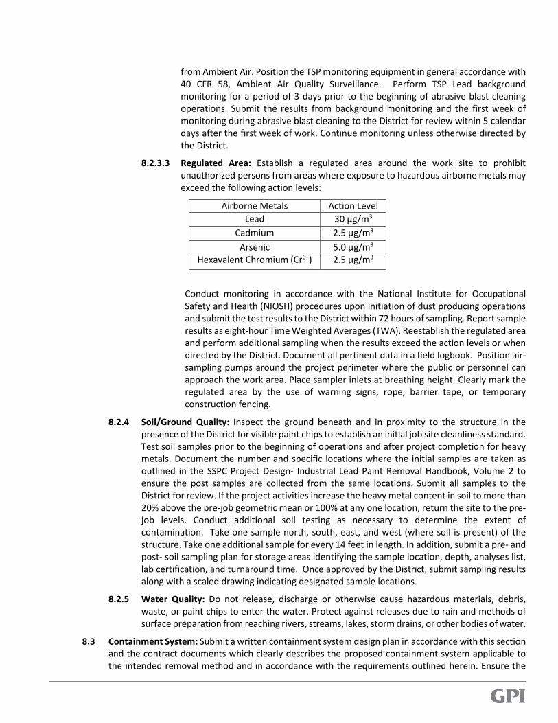
from Ambient Air. Position the TSP monitoring equipment in general accordance with
40 CFR 58, Ambient Air Quality Surveillance. Perform TSP Lead background
monitoring for a period of 3 days prior to the beginning of abrasive blast cleaning
operations. Submit the results from background monitoring and the first week of
monitoring during abrasive blast cleaning to the District for review within 5 calendar
days after the first week of work. Continue monitoring unless otherwise directed by
the District.
8.2.3.3 Regulated Area: Establish a regulated area around the work site to prohibit
unauthorized persons from areas where exposure to hazardous airborne metals may
exceed the following action levels:
Airborne Metals Action Level
Lead 30 µg/m3
Cadmium 2.5 µg/m3
Arsenic 5.0 µg/m3
Hexavalent Chromium (Cr6+) 2.5 µg/m3
Conduct monitoring in accordance with the National Institute for Occupational
Safety and Health (NIOSH) procedures upon initiation of dust producing operations
and submit the test results to the District within 72 hours of sampling. Report sample
results as eight-hour Time Weighted Averages (TWA). Reestablish the regulated area
and perform additional sampling when the results exceed the action levels or when
directed by the District. Document all pertinent data in a field logbook. Position air-
sampling pumps around the project perimeter where the public or personnel can
approach the work area. Place sampler inlets at breathing height. Clearly mark the
regulated area by the use of warning signs, rope, barrier tape, or temporary
construction fencing.
8.2.4 Soil/Ground Quality: Inspect the ground beneath and in proximity to the structure in the
presence of the District for visible paint chips to establish an initial job site cleanliness standard.
Test soil samples prior to the beginning of operations and after project completion for heavy
metals. Document the number and specific locations where the initial samples are taken as
outlined in the SSPC Project Design- Industrial Lead Paint Removal Handbook, Volume 2 to
ensure the post samples are collected from the same locations. Submit all samples to the
District for review. If the project activities increase the heavy metal content in soil to more than
20% above the pre-job geometric mean or 100% at any one location, return the site to the pre-
job levels. Conduct additional soil testing as necessary to determine the extent of
contamination. Take one sample north, south, east, and west (where soil is present) of the
structure. Take one additional sample for every 14 feet in length. In addition, submit a pre- and
post- soil sampling plan for storage areas identifying the sample location, depth, analyses list,
lab certification, and turnaround time. Once approved by the District, submit sampling results
along with a scaled drawing indicating designated sample locations.
8.2.5 Water Quality: Do not release, discharge or otherwise cause hazardous materials, debris,
waste, or paint chips to enter the water. Protect against releases due to rain and methods of
surface preparation from reaching rivers, streams, lakes, storm drains, or other bodies of water.
8.3 Containment System: Submit a written containment system design plan in accordance with this section
and the contract documents which clearly describes the proposed containment system applicable to
the intended removal method and in accordance with the requirements outlined herein. Ensure the

plan includes, but is not limited to, removal method; methods for collecting debris; and containment
enclosure components. Use fire retardant materials. Provide containment drawings, calculations, and
assumptions, including ventilation criteria if applicable, signed and sealed by a Specialty Engineer.
Provide a complete structural impact analysis prepared by the Specialty Engineer to verify the existing
structure can withstand the additional dead, live and wind loads imposed by the containment system,
signed and sealed by the Specialty Engineer. Include a clear description of the ventilation system
components. Design ventilation meeting the requirements of this specification; SSPC Guide No.6; and
cross draft of 100 feet per minute and downdraft of 50-60 feet per minute.
Isolate the immediate area of the structure to ensure compliance with current and permit requirements
for air, water, soil, and pollution prevention. Protect the containment system from vehicular and
pedestrian traffic. Ensure paint, paint chips, or other debris will not fall outside of the containment area
under any circumstances. Repair any damage created by fastening, bracing, or handling the scaffolding
and staging. If a suspended platform is constructed, use rigid or flexible materials as needed to create
an air and dust impenetrable enclosure. Verify the platform and its components are designed and
constructed to support at least four times its maximum intended load without failure, with wire cables
capable of supporting at least six times their maximum intended load without failure. Strictly comply
with all applicable OSHA regulations regarding scaffolding. Prior to use, the must verify, in the field, the
containment and staging has been erected in accordance with the signed and sealed plan. Any
changes to the accepted signed, sealed and accepted plan must be made, re-signed and re-sealed by
the Specialty Engineer and submitted to the District for review and acceptance.
8.4 Worker Protection: Comply with the requirements of OSHA 29 CFR 1926 and applicable portions of 29
CFR 1910. Include specific programs as required by 29 CFR 1926.62 (lead), 29 CFR 1926.1118 (inorganic
arsenic), 29 CFR 1926.1126 (hexavalent chromium), and 29 CFR 1926.1127 (cadmium) when these
hazardous agents are present. Implement appropriate safety procedures for all hazards on the job site
whether specifically identified herein or not.
9 WASTE HANDLING AND MANAGEMENT.
9.1 General: Prepare a waste management program plan which addresses the applicable requirements
from EPA regulations for hazardous waste management and the Contract Documents. Include
provisions for the handling and disposal of non- hazardous waste. Dispose of all waste in accordance
with all federal, state, and local laws and regulations.
9.2 Collection and Handling of Waste: Properly classify, package, and store all paint removal debris, both
solid and liquid in accordance with SSPC Guide 7, “Guide for the Disposal of Lead-Contaminated Surface
Preparation Debris, the Federal Water Pollution Control”, Act with amendments, and all other
current government regulations and guidelines. Comply with the Resource Conservation and Recovery
Act to include, at a minimum, CFR 40 260 through CFR 40 268. Prior to identification and storage,
separate solid and liquid waste, and separate individual waste streams.
9.3 Testing and Analysis: Laboratory analyses for all waste stream and environmental samples shall be
conducted by an EPA certified, independent laboratory with an approved Quality Assurance Plan.
Laboratory analyses for worker monitoring and regulated area samples shall be conducted by an
American Industrial Hygiene Association (AIHA) metals accredited laboratory. Provide a copy of all
sampling and test reports no later than 72 hours after collection of samples.
9.4 Waste Identification: Collect samples in accordance with EPA SW 846, Test Methods for Evaluating
Solid Waste - Physical/Chemical Methods. Use a random and representative sampling technique.
Collect a minimum of four representative samples of each waste stream. These waste streams include,
but are not limited to, water, paint chips, dust, and paint chips mixed with disposable abrasives and
debris. Complete the initial sampling of each waste stream immediately upon filling the first drum, but
do not allow waste to accumulate for longer than 7 days before sampling. After the representative
samples are collected, send them immediately to the EPA certified laboratory for analysis. Unless
otherwise directed by the District, required by State regulations, or required by the waste recycling
or disposal facility, once each waste stream is sampled, tested, and classified, additional sampling and
analysis are not required for subsequent shipments unless the waste stream changes. Submit samples
to an approved laboratory to be tested for arsenic, barium, cadmium, hexavalent chromium, lead,
mercury, selenium, and silver in accordance with EPA Method 3050 and Method 6010 (content) and
EPA Method 1311, Toxicity Characteristics Leaching Procedures (TCLP). Clearly label each sample with
sample number, date and time of sampling, name of collector, and location of collection. Maintain
chain of custody forms for each sample. Enter each sample on a sample analysis request form. Enter
sample numbers, type of waste, amount of each sample, distribution of samples, signature and all other
information into field logbook.
9.5 Waste Storage: Collect waste from the control devices, equipment, and all work surfaces on a daily
basis. Keep hazardous and non-hazardous waste separate. Do not mix blasting debris with any other
type of waste. Place waste in approved storage drums. Locate all hazardous waste within a regulated
area. The maximum weight for each drum, when filled, is 821 pounds. Properly seal and label all drums.
Transport waste storage drums to a secured, marked, temporary storage area. Locate the temporary
storage area on well- drained ground not susceptible to flooding or storm water run-off. Place drums
on a pallet and cover with fiber reinforced, impermeable tarpaulins. Store drums no more than two
drums wide and two drums high. Arrange drums so that labels are easily readable. Do not store waste
in the temporary storage area longer than 90 days.
9.6 Waste Disposal: Transport, treat and dispose of all hazardous and non-hazardous waste. Notify the
District a minimum of three weeks prior to the date of shipment of any waste to an off- site facility.
Provide the District with documentation that the receiving disposal facilities are properly licensed.
Provide manifests for all hazardous and non-hazardous waste shipments. Identify any waste disposal
subcontractors and provide a copy of their licensing to perform waste disposal and transport
operations. Do not use any products intended for the pre-treatment of waste.
9.7 Permits: The Contractor is responsible for all liability resulting from non-compliance with pertinent
rules and regulations including permit requirements.