switching over voltages in offshore cable connections
TRANSCRIPT

Switching Over Voltages in Offshore Cable Connections
Nidhi Parmar1, Chetan Kotwal2, Tarang Thakkar3 and Prakash Makhijani3 1 PG Student, S V I T, Vasad, Gujarat, India.
2Professor, S V I T, Vasad, Gujarat, India. 3Director of Ohm EnconVadodara, Gujarat, India.
[email protected], [email protected], [email protected], [email protected]
Abstract Switching overvoltages are the major concern with the cable system. For insulation
coordination and design aspects one should know the range of this overvoltages. Different overvoltages and its effects on the system protection are described here. Some of mitigation techniques for switching transients are also listed. In this paper subsea cable system is considered for the simulation. Simulation has been done in PSCAD/EMTDC. By simulating different cases selection of rated impulse voltage for the equipments are defined.
1 Introduction In electrical power system, transmission network plays an important role between electrical energy
production and consumption. The transmission networks have mainly two types: Overhead lines (OHL) and underground cable system. Now a days expansion of overhead lines are become difficult therefore the underground cable system is introduced. Use of underground cable has great impact on quality of power and also on the protection level. Moreover offshore infrastructures are also increasing which also need electrical power. On offshore platforms over head transmission are complicated and also economically larger therefore cabling system is most widely used. Offshore industries such as oil, gas or wind power generation require connecting with the onshore grid. Although offshore industry may have its own generation, it requires electrical connection between productions platforms. Use of cabling system is beneficial and also it is easy to install but we cannot ignore the high frequency current and voltage transients resulting from the switching operation. It is crucial to address the impact of this transient on the design requirements, not only for extra high voltage (EHV) system but also in the case of medium transmission voltage such as 11kV systems.
In transmission line as voltage level increases switching transients are become more important. External lightning voltages are limited which leads switching transients to become a primary concern
Kalpa Publications in EngineeringVolume 1, 2017, Pages 586–592
ICRISET2017. International Conference on Re-search and Innovations in Science, Engineering&Technology. Selected Papers in Engineering
A. Shukla, J.M. Patel, P.D. Solanki, K.B. Judal, R.K. Shukla, R.A. Thakkar, N.P. Gajjar, N.J. Kothari, S.Saha, S.K. Joshi, S.R. Joshi, P. Darji, S. Dambhare, B.R. Parekh, P.M. George, A.M. Trivedi, T.D. Pawar,M.B. Shah, V.J. Patel, M.S. Holia, R.P. Mehta, J.M. Rathod, B.C. Goradiya and D.K. Patel (eds.),ICRISET2017 (Kalpa Publications in Engineering, vol. 1), pp. 586–592

in insulation coordination[1]. Also the insulation has lowest strength for switching surges with regard to long air gap[2]. The main source of transient overvoltages in overhead lines is lightning, whereas in cable systems overvoltages are mainly caused by circuit breaker operations [3].
In this paper, the overview of switching transients its causes and reduction techniques are described. Importance of switching overvoltage studies and its contribution in insulation coordination is discussed. This paper focuses on transients, arises from cable energization and switching operations. Electrical network connecting offshore platforms is simulated in PSCAD/EMTDC. Transients in AC cable connections are measured for insulation coordination and system design.
2 Overvoltage Phenomenon According to their shape and duration, voltage and overvoltages can be classified in five types.
These are Continuous Operating Voltage, Temporary Over voltages, Slow Front (switching), Fast Front (lightning) and Very Fast Front[4].
a) Temporary overvoltages (TOV) : This overvoltage if of power frequency and having a slowly decaying amplitude. They are mainly due to transformer energization, fault overvoltages, overvoltages due to load rejection etc.
b) Slow front transients: These are of small duration of few milliseconds or less. They are usually highly damped and unidirectional. The can originate from switching operations, line energization, transformer energization and reactive compensation operations. Studies say that disconnection transients can produce higher overvoltages then cable energization[5].
c) Fast front transients: They are mainly associated with lightning strokes and are characterized by the standard lightning impulse wave (1.2/50 µs).
However, in cabling system overvoltages are mainly caused by switching operation, switching overvoltages are major concern. For transmission line, practical rules and modeling suggestions to evaluate switching transient simulation are provided in [6]. The switching overvoltages are strongly affected by line length and are higher in cable as compared to overhead line.
Mathematical derivation of switching transients is also useful to have an idea about overvoltage amplitude and frequency. Let us analyze series connected RLC circuit with an AC source mathematically [7][1].
Circuit can be described by,
Vp sin ωt + θ = RI + LdIdt+1C
Idt (1)
The current is a summation of the forced and homogeneous components. I t = I1 t + I2(t) (2)
The forced component is the steady-state component and it is easy to obtain by using phasors.
I1 t =Vp
R5 + ωL − 789
5sin ωt + θ − tan<7
ωL − 789
R (3)
The transient component is a result of an exchange of energy between the capacitor and the inductor that it is eventually damped by the resistance.
Here, characteristic equation of circuit is... s5 +
RLs +
1LC
= 0 (4)
s1, s2 = −
R2L
±R2L
5
−1LC
(5)
Switching Overvoltages in Offshore Cable... N. Parmar, C. Kotwal, T. Thakkar and P. Makhijani
587
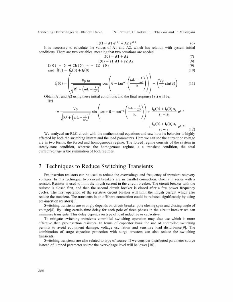
I t = A1eC7.E + A2eC5.E (6) It is necessary to calculate the values of A1 and A2, which has relation with system initial
conditions. There are two variables, meaning that two equations are needed. I 0 = A1 + A2 (7) I(0) = s1. A1 + s2. A2 (8) I(0) = 0 → Ih(0) = - If (0) (9) and I 0 = I2 0 + I1 0 (10)
I2 0 =Vpω
R5 + ωL − 789
5cos θ − tan<7
ωL − 789
R−
VpLsin θ (11)
Obtain A1 and A2 using these initial conditions and the final response I (t) will be,
I t
=Vp
R5 + ωL − 789
5sin ωt + θ − tan<7
ωL − 789
R+I2 0 + I1(0)s5
s7 − s5eCHE
+I2 0 + I1(0)s7
s5 − s7eCIE (12)
We analyzed an RLC circuit with the mathematical equations and saw how its behavior is highly affected by both the switching instant and the load parameters. Here we can see the current or voltage are in two forms, the forced and homogeneous regime. The forced regime consists of the system in steady-state condition, whereas the homogenous regime is a transient condition, the total current/voltage is the summation of both regimes.
3 Techniques to Reduce Switching Transients Pre-insertion resistors can be used to reduce the overvoltage and frequency of transient recovery
voltages. In this technique, two circuit breakers are in parallel connection. One is in series with a resistor. Resistor is used to limit the inrush current in the circuit breaker. The circuit breaker with the resistor is closed first, and then the second circuit breaker is closed after a few power frequency cycles. The first operation of the resistive circuit breaker will limit the inrush current which also reduce the transient. The transients in an offshore connection could be reduced significantly by using pre-insertion resistors[1].
Switching transients are strongly depends on circuit breaker pole closing span and closing angle of voltage[8]. By using certain time delay for each pole of three phases in the circuit breaker we can minimize transients. This delay depends on type of load inductive or capacitive.
To mitigate switching transients controlled switching operation may also use which is more effective then pre-insertion resistors. In terms of capacitor bank the use of controlled switching permits to avoid equipment damage, voltage oscillation and sensitive load disturbance[9]. The combination of surge capacitor protection with surge arresters can also reduce the switching transients.
Switching transients are also related to type of source. If we consider distributed parameter source instead of lumped parameter source the overvoltage level will be lower [10].
Switching Overvoltages in Offshore Cable... N. Parmar, C. Kotwal, T. Thakkar and P. Makhijani
588

4 Simulation
4.1 System Description There are six offshore platforms connected by a cables, platform-A, B, C1, C2, C3 and C4.
Platform-A feeding a platform-B through 11kv subsea umbilical. 11/0.72 kV transformers located on platform-B to step down the voltage. 690V 3-phase 3 wire 50Hz bus forwarding the power to platform-C1, C2, C3 and C4. Single line diagram of a system is shown in the Fig.1. Simulation of the
given system is done in PSCAD/EMTDC.
4.2 Simulation cases Following simulations have been done to the system.
• Energization of 11kV Cable from platform-A circuit breaker. • Energization of all three 690V from 690V bus circuit breaker. • Switching operations at peak and zero voltage value.
The purpose of this analysis is to evaluate the overvoltage level and inrush currents due to feeder energization.
Figure 1 Single line diagram of the system
Switching Overvoltages in Offshore Cable... N. Parmar, C. Kotwal, T. Thakkar and P. Makhijani
589

5 Result Simulation results are shown in Figure 2. And results are also tabulated in Table-1. According to
simulation results required impulse withstand level and rated insulation voltages are also defined in Table-1.
Figure 2 Result of the simulation cases (a) - (h)
(a) 11kV cable energization at zero voltage
(b) 11kV cable energization at peak voltage
(c) 690V cable energization connected to pl-C2 at zero voltage
(d) 690V cable energization connected to pl-C2 at peak voltage
(e) 690V cable energization connected to pl-C3 at zero voltage
(f) 690V cable energization connected to pl-C3 at peak voltage
(g) 690V cable energization connected to pl-C4 at zero voltage
(h) 690V cable energization connected to pl-C4 at peak voltage
Switching Overvoltages in Offshore Cable... N. Parmar, C. Kotwal, T. Thakkar and P. Makhijani
590

Table 1 Cable energization results
System voltage
(kV)
Energizing at voltage instant
Van
Max. Switching OV
surge (kV)
TOV Equipment impulse withstand
level (kV)
Equipment rated insulation
voltage (kV) 11 Zero 18.1 - 75 12 11 Peak 20.1 - 75 12
0.69 Zero 1.19 - 8 1 0.69 Peak 1.30 - 8 1 0.69 Zero 0.91 - 8 1 0.69 Peak 1.02 - 8 1 0.69 Zero 1.13 - 8 1 0.69 Peak 1.26 - 8 1
The following criteria are used to determine the equipment rated insulation voltage and impulse
withstand voltage: • Maximum switching overvoltage from simulation study. • Maximum temporary overvoltages from simulation study. • Equipment availability in the market.
From the results, following observation can be made: • Maximum switching impulse overvoltage form various switching cases in 11kV system
is 20.1 kV. • Maximum switching impulse overvoltage form various switching cases in 690V system
is 1.30 kV. • Temporary overvoltage (Power frequency overvoltage) does not occur.
Cable inrush currents are produced due to charging process of the system capacitance. The inrush currents should be accounted in determining protection setting.
6 Conclusion Switching transients are the major overvoltages in cable system. Subsea cable system is simulated
using PSCAD/EMTDC. According to the simulation results equipment impulse withstand voltage and equipment rated insulation voltage are specified. Each circuit of the assembly is capable of withstanding temporary overvoltages and transient overvoltages.
References [1] J. C. Das, "Transients in electrical systems-Analysis, recognition and mitigation", McGraw
Hill, 2010. [2] M. S. Naidu, "High voltage engineering", McGraw Hill, 2009. [3] A. Greenwood, "Electrical transients in power systems", Wiley, Second edition. 1991. [4] "Insulation Co-ordination, Part 1: Definitions, Principles and Rules", IEC 60071-1 [5] R. King, F. Moore, N. Jenkins, A. Haddad, H. Griffiths and M. Osborne, "Switching
transients in offshore wind farms – impact on the offshore and onshore networks", International Conference on Power Systems Transients, 2011.
Switching Overvoltages in Offshore Cable... N. Parmar, C. Kotwal, T. Thakkar and P. Makhijani
591

[6] Ibrahim A, Dommel H, "A Knowledge Base for Switching Surge Transients", the International Conference on Power Systems Transients (IPST’05), 2005.
[7] Filipe Faria da silva, Claus Leth Bak, "Electromagnetic transients in power cables", Springer, 2013.
[8] Daud M, Ciufo P, Perera S, "Statistical Analysis of Over voltages due to the Energization of a 132 kV Underground Cable", 6th International Conference on Electrical Engineering/Electronics, Computer, Telecommunications and Information Technology, 2009.
[9] Paul C. Fernandez , Paul C. V. Esmeraldo, Jorge Amon Filho, Cesar Ribeiro Zani, "Use of controlled switching systems in power system to mitigate switching transients. trends and benefits - Brazilian experience", Transmission and Distribution Conference and Exposition, 2004 IEEE/PES
[10] Teruo Ohno, Member, Claus Leth Bak, Akihiro Ametani, Wojciech Wiechowski and Thomas Kjærsgaard Sørensen, “Statistical Distribution of Energization Over voltages of EHV Cables", IEEE Transactions on Power Delivery, 2013.
[11] F. Moore, A. Haddad, "Switching transients in long AC cable connections to offshore wind farms", 46th International Universities' Power Engineering Conference, UPEC 2011.
[12] Analysis of switching transient overvoltages in the power system off loading production storage and offloading vessel , Electric Power Systems Research , Elsevier, 2014
[13] Tao zhang, Lliuxue sun, and Yin zhang, "Study on switching overvoltage in off-shore wind farms", IEEE transactions on applied superconductivity, vol. 24, 2014.
Switching Overvoltages in Offshore Cable... N. Parmar, C. Kotwal, T. Thakkar and P. Makhijani
592