sysmac library user’s manual for mc command table library filethe mc command table library is used...
TRANSCRIPT
Sysmac Library
User’s Manual for MC Command Table Library
W545-E1-04
SYSMAC-XR002
All rights reserved. No part of this publication may be reproduced, stored in a retrieval system, or transmitted, in any form, or by any means, mechanical, electronic, photocopying, recording, or otherwise, without the prior written permission of OMRON.
No patent liability is assumed with respect to the use of the information contained herein. Moreover, because OMRON is constantly striving to improve its high-quality products, the information contained in this manual is subject to change without notice. Every precaution has been taken in the preparation of this manual. Neverthe-less, OMRON assumes no responsibility for errors or omissions. Neither is any liability assumed for damages resulting from the use of the information contained in this publication.
• Sysmac and SYSMAC are trademarks or registered trademarks of OMRON Corporation in Japan and other countries for OMRON factory automation products.
• Microsoft, Windows, Windows Vista, Excel, and Visual Basic are either registered trademarks or trademarks of Microsoft Corporation in the United States and other countries.
• EtherCAT® is registered trademark and patented technology, licensed by Beckhoff Automation GmbH, Germany.
• ODVA, CIP, CompoNet, DeviceNet, and EtherNet/IP are trademarks of ODVA.
• The SD and SDHC logos are trademarks of SD-3C, LLC.
Other company names and product names in this document are the trademarks or registered trademarks of their respective companies.
Trademarks
Copyrights
NOTE
Microsoft product screen shots reprinted with permission from Microsoft Corporation.
1
Introduction
Sysmac Library User’s Manual for MC Command Table Library (W545)
Introduction
Thank you for purchasing an NJ/NX-series CPU Unit or an NY-series Industrial PC.
This manual provides information required to use the function blocks in the MC Command Table Library. (“Function block” is sometimes abbreviated as “FB.”) Please read this manual and make sure you understand the functionality and performance of the NJ/NX-series CPU Unit before you attempt to use it in a control system.
This manual contains the specifications of the Function Block. It does not include restrictions on use of the Controller, Units, or components, or restrictions due to combinations. Make sure to read the user's manual for each product before use.
Keep this manual in a safe place where it will be available for reference during operation.
The MC Command Table Library is used to continuously perform positioning that the MC Function Mod-ule is used. You can use this library together with motion control instructions of the NJ/NX/NY-series Controller.
The program that multiple motion control instructions are used will be unnecessary by using this library.
Refer to the motion control instructions reference manual for details on motion control instructions of the NJ/NX/NY-series Controller.
This manual is intended for the following personnel, who must also have knowledge of electrical sys-tems (an electrical engineer or the equivalent).
• Personnel in charge of introducing FA systems.
• Personnel in charge of designing FA systems.
• Personnel in charge of installing and maintaining FA systems.
• Personnel in charge of managing FA systems and facilities.
For programming, this manual is intended for personnel who understand the programming language specifications in international standard IEC 61131-3 or Japanese standard JIS B 3503.
Features of the Library
Intended Audience
Introduction
2 Sysmac Library User’s Manual for MC Command Table Library (W545)
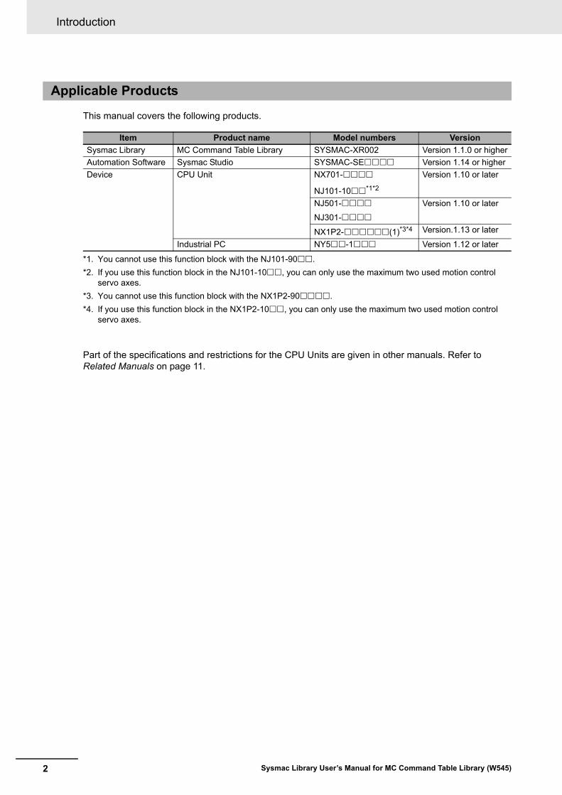
This manual covers the following products.
Part of the specifications and restrictions for the CPU Units are given in other manuals. Refer to Related Manuals on page 11.
Applicable Products
Item Product name Model numbers Version
Sysmac Library MC Command Table Library SYSMAC-XR002 Version 1.1.0 or higher
Automation Software Sysmac Studio SYSMAC-SE Version 1.14 or higher
Device CPU Unit NX701-
NJ101-10*1*2
*1. You cannot use this function block with the NJ101-90.
*2. If you use this function block in the NJ101-10, you can only use the maximum two used motion control servo axes.
Version 1.10 or later
NJ501-
NJ301-
Version 1.10 or later
NX1P2-(1)*3*4
*3. You cannot use this function block with the NX1P2-90.
*4. If you use this function block in the NX1P2-10, you can only use the maximum two used motion control servo axes.
Version.1.13 or later
Industrial PC NY5-1 Version 1.12 or later
3
Manual Structure
Sysmac Library User’s Manual for MC Command Table Library (W545)
Manual Structure
Special information in this manual is classified as follows:
Precautions for Safe Use
Precautions on what to do and what not to do to ensure safe usage of the product.
Precautions for Correct Use
Precautions on what to do and what not to do to ensure proper operation and performance.
Additional Information
Additional information to read as required.This information is provided to increase understanding or make operation easier.
Version Information
Information on differences in specifications and functionality for CPU Units and Industrial PCs with different unit versions and for different versions of the Sysmac Studio are given.
Note References are provided to more detailed or related information.
Special Information
CONTENTS
4 Sysmac Library User’s Manual for MC Command Table Library (W545)
CONTENTS
Introduction ..............................................................................................................1Features of the Library................................................................................................................................. 1Intended Audience....................................................................................................................................... 1Applicable Products ..................................................................................................................................... 2
Manual Structure ......................................................................................................3Special Information ...................................................................................................................................... 3
CONTENTS................................................................................................................4
Terms and Conditions Agreement ..........................................................................6Warranty, Limitations of Liability .................................................................................................................. 6Application Considerations .......................................................................................................................... 7Disclaimers .................................................................................................................................................. 7
Safety Precautions ...................................................................................................8Definition of Precautionary Information........................................................................................................ 8Symbols ....................................................................................................................................................... 8Cautions....................................................................................................................................................... 9
Precautions for Correct Use..................................................................................10
Related Manuals ..................................................................................................... 11
Revision History .....................................................................................................13Procedure to Use Sysmac Libraries ........................................................................................... 1-15
Procedure to Use Sysmac Libraries Installed Using the Installer ........................................................... 1-16Procedure to Use Sysmac Libraries Uploaded from a CPU Unit or an Industrial PC............................. 1-20
Common Specifications of Function Blocks.............................................................................. 1-23Common Variables ................................................................................................................................. 1-24Precautions............................................................................................................................................. 1-30
Individual Specifications of Function Blocks.................................................................................................................. 1-31MCCmdTbl.............................................................................................................................................. 1-32
Appendix ....................................................................................................................................... 1-59Referring to Library Information .............................................................................................................. 1-60Referring to Function Block and Function Source Codes....................................................................... 1-63

5
CONTENTS
Sysmac Library User’s Manual for MC Command Table Library (W545)
Terms and Conditions Agreement
6 Sysmac Library User’s Manual for MC Command Table Library (W545)
Terms and Conditions Agreement
Exclusive Warranty
Omron’s exclusive warranty is that the Products will be free from defects in materials and workman-ship for a period of twelve months from the date of sale by Omron (or such other period expressed in writing by Omron). Omron disclaims all other warranties, express or implied.
Limitations
OMRON MAKES NO WARRANTY OR REPRESENTATION, EXPRESS OR IMPLIED, ABOUT NON-INFRINGEMENT, MERCHANTABILITY OR FITNESS FOR A PARTICULAR PURPOSE OF THE PRODUCTS. BUYER ACKNOWLEDGES THAT IT ALONE HAS DETERMINED THAT THE PRODUCTS WILL SUITABLY MEET THE REQUIREMENTS OF THEIR INTENDED USE.
Omron further disclaims all warranties and responsibility of any type for claims or expenses based on infringement by the Products or otherwise of any intellectual property right.
Buyer Remedy
Omron’s sole obligation hereunder shall be, at Omron’s election, to (i) replace (in the form originally shipped with Buyer responsible for labor charges for removal or replacement thereof) the non-com-plying Product, (ii) repair the non-complying Product, or (iii) repay or credit Buyer an amount equal to the purchase price of the non-complying Product; provided that in no event shall Omron be responsible for warranty, repair, indemnity or any other claims or expenses regarding the Products unless Omron’s analysis confirms that the Products were properly handled, stored, installed and maintained and not subject to contamination, abuse, misuse or inappropriate modification. Return of any Products by Buyer must be approved in writing by Omron before shipment. Omron Companies shall not be liable for the suitability or unsuitability or the results from the use of Products in combi-nation with any electrical or electronic components, circuits, system assemblies or any other materi-als or substances or environments. Any advice, recommendations or information given orally or in writing, are not to be construed as an amendment or addition to the above warranty.
See http://www.omron.com/global/ or contact your Omron representative for published information.
OMRON COMPANIES SHALL NOT BE LIABLE FOR SPECIAL, INDIRECT, INCIDENTAL, OR CON-SEQUENTIAL DAMAGES, LOSS OF PROFITS OR PRODUCTION OR COMMERCIAL LOSS IN ANY WAY CONNECTED WITH THE PRODUCTS, WHETHER SUCH CLAIM IS BASED IN CONTRACT, WARRANTY, NEGLIGENCE OR STRICT LIABILITY.
Further, in no event shall liability of Omron Companies exceed the individual price of the Product on which liability is asserted.
Warranty, Limitations of Liability
Warranties
Limitation on Liability; Etc
7
Terms and Conditions Agreement
Sysmac Library User’s Manual for MC Command Table Library (W545)
Omron Companies shall not be responsible for conformity with any standards, codes or regulations which apply to the combination of the Product in the Buyer’s application or use of the Product. At Buyer’s request, Omron will provide applicable third party certification documents identifying ratings and limitations of use which apply to the Product. This information by itself is not sufficient for a com-plete determination of the suitability of the Product in combination with the end product, machine, sys-tem, or other application or use. Buyer shall be solely responsible for determining appropriateness of the particular Product with respect to Buyer’s application, product or system. Buyer shall take applica-tion responsibility in all cases.
NEVER USE THE PRODUCT FOR AN APPLICATION INVOLVING SERIOUS RISK TO LIFE OR PROPERTY WITHOUT ENSURING THAT THE SYSTEM AS A WHOLE HAS BEEN DESIGNED TO ADDRESS THE RISKS, AND THAT THE OMRON PRODUCT(S) IS PROPERLY RATED AND INSTALLED FOR THE INTENDED USE WITHIN THE OVERALL EQUIPMENT OR SYSTEM.
Omron Companies shall not be responsible for the user’s programming of a programmable Product, or any consequence thereof.
Data presented in Omron Company websites, catalogs and other materials is provided as a guide for the user in determining suitability and does not constitute a warranty. It may represent the result of Omron’s test conditions, and the user must correlate it to actual application requirements. Actual perfor-mance is subject to the Omron’s Warranty and Limitations of Liability.
Product specifications and accessories may be changed at any time based on improvements and other reasons. It is our practice to change part numbers when published ratings or features are changed, or when significant construction changes are made. However, some specifications of the Product may be changed without any notice. When in doubt, special part numbers may be assigned to fix or establish key specifications for your application. Please consult with your Omron’s representative at any time to confirm actual specifications of purchased Product.
Information presented by Omron Companies has been checked and is believed to be accurate; how-ever, no responsibility is assumed for clerical, typographical or proofreading errors or omissions.
Application Considerations
Suitability of Use
Programmable Products
Disclaimers
Performance Data
Change in Specifications
Errors and Omissions
Safety Precautions
8 Sysmac Library User’s Manual for MC Command Table Library (W545)
Safety Precautions
The following notation is used in this user’s manual to provide precautions required to ensure safe usage of an NJ/NX-series CPU Unit and an NY-series Industrial PC.
The safety precautions that are provided are extremely important to safety. Always read and heed the information provided in all safety precautions.
The following notation is used.
Definition of Precautionary Information
Symbols
The circle and slash symbol indicates operations that you must not do.
The specific operation is shown in the circle and explained in text.
This example indicates prohibiting disassembly.
The triangle symbol indicates precautions (including warnings).
The specific operation is shown in the triangle and explained in text.
This example indicates a precaution for electric shock.
The triangle symbol indicates precautions (including warnings).
The specific operation is shown in the triangle and explained in text.
This example indicates a general precaution.
The filled circle symbol indicates operations that you must do.
The specific operation is shown in the circle and explained in text.
This example shows a general precaution for something that you must do.
WARNING
Caution
Indicates a potentially hazardous situation which, if not avoided, could result in death or serious injury. Addition-ally, there may be severe property damage.
Indicates a potentially hazardous situation which, if not avoided, may result in minor or moderate injury, or property damage.
9
Safety Precautions
Sysmac Library User’s Manual for MC Command Table Library (W545)
Cautions
Caution
Read all related manuals carefully before you use this library.
Emergency stop circuits, interlock circuits, limit circuits, and similar safety measures must be provided in external control circuits.
Check the user program, data, and parameter settings for proper execution before you use them for actual operation.
Precautions for Correct Use
10 Sysmac Library User’s Manual for MC Command Table Library (W545)
Precautions for Correct Use
• When you use the library, functions or function blocks that are not described in the library manual may be displayed on the Sysmac Studio. Do not use functions or function blocks that are not described in the manual.
• The sample programming shows only the portion of a program that uses the function or function block from the library.
• When using actual devices, also program safety circuits, device interlocks, I/O with other devices, and other control procedures.
• Create a user program that will produce the intended device operation.
• Check the user program for proper execution before you use it for actual operation.
• When you use the NX-series CPU Unit, use the _MC_AX[0..63] (Axis Variable) system-defined vari-able. If you use the axis variables _MC_AX1 and _MC_AX2, unintended operation may occur for the system.
• When you use the NX-series CPU Unit, do not use this function block for other than the specified tasks. Unintended operation may occur for the system.
• When you perform memory operation, make sure that servo is ON at all times. When you set the servo to OFF during memory operation, set Enable to FALSE in the function block. If you do not set Enable to FALSE in the function block, unintended operation may occur.
• When you stop memory operation and then restart it again, retain CurrentSeqNo (Executing Sequence Number) in order to start from the sequence number at which memory operation was stopped.
• During memory operation, do not perform the multi-execution of instructions regarding the axis/axes group used for memory operation.
• If you execute the MC_Stop or MC_GroupStop instruction during M Code output, the axis/axes group will start motion again after M Code reset. For a deceleration stop during memory operation, set Stop (Stop Execution) to TRUE in the function block, and do not use the MC_Stop or MC_GroupStop instruction.
• If you perform an immediate stop for memory operation, execute the MC_ImmediateStop instruction for all axes being used in memory operation. During a single-axis discrete motion, the axis will not stop even if you execute the MC_GroupImmediateStop instruction.
Using the Library
Using Sample Programming
Operation
11
Related Manuals
Sysmac Library User’s Manual for MC Command Table Library (W545)
Related Manuals
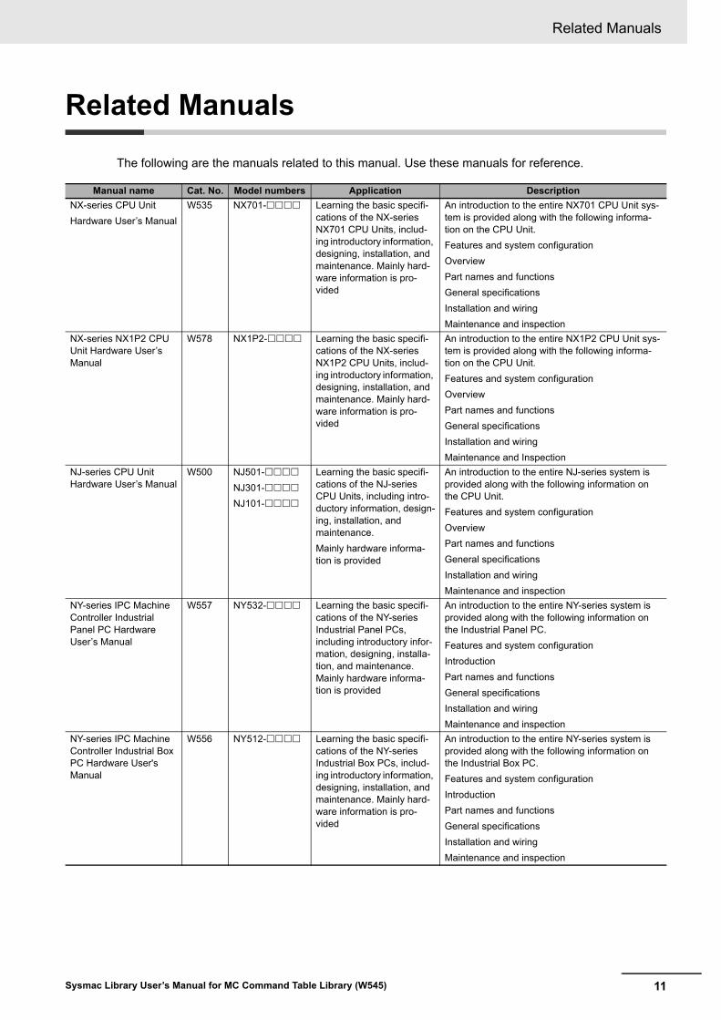
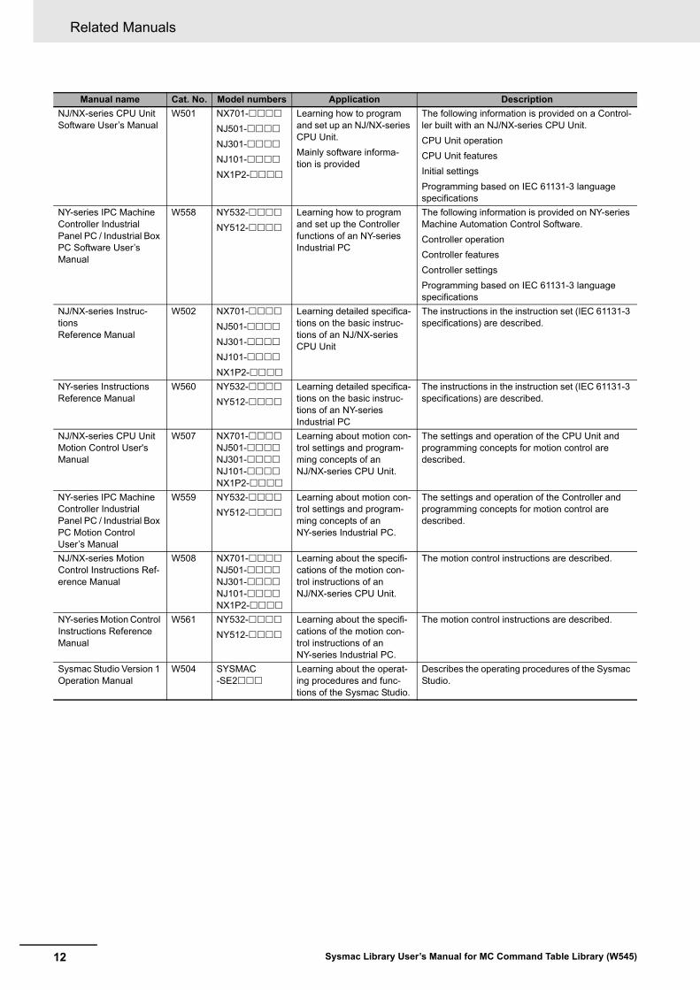
The following are the manuals related to this manual. Use these manuals for reference.
Manual name Cat. No. Model numbers Application Description
NX-series CPU Unit
Hardware User’s Manual
W535 NX701- Learning the basic specifi-cations of the NX-series NX701 CPU Units, includ-ing introductory information, designing, installation, and maintenance. Mainly hard-ware information is pro-vided
An introduction to the entire NX701 CPU Unit sys-tem is provided along with the following informa-tion on the CPU Unit.
Features and system configuration
Overview
Part names and functions
General specifications
Installation and wiring
Maintenance and inspection
NX-series NX1P2 CPU Unit Hardware User’s Manual
W578 NX1P2- Learning the basic specifi-cations of the NX-series NX1P2 CPU Units, includ-ing introductory information, designing, installation, and maintenance. Mainly hard-ware information is pro-vided
An introduction to the entire NX1P2 CPU Unit sys-tem is provided along with the following informa-tion on the CPU Unit.
Features and system configuration
Overview
Part names and functions
General specifications
Installation and wiring
Maintenance and Inspection
NJ-series CPU Unit Hardware User’s Manual
W500 NJ501-
NJ301-
NJ101-
Learning the basic specifi-cations of the NJ-series CPU Units, including intro-ductory information, design-ing, installation, and maintenance.
Mainly hardware informa-tion is provided
An introduction to the entire NJ-series system is provided along with the following information on the CPU Unit.
Features and system configuration
Overview
Part names and functions
General specifications
Installation and wiring
Maintenance and inspection
NY-series IPC Machine Controller Industrial Panel PC Hardware User’s Manual
W557 NY532- Learning the basic specifi-cations of the NY-series Industrial Panel PCs, including introductory infor-mation, designing, installa-tion, and maintenance. Mainly hardware informa-tion is provided
An introduction to the entire NY-series system is provided along with the following information on the Industrial Panel PC.
Features and system configuration
Introduction
Part names and functions
General specifications
Installation and wiring
Maintenance and inspection
NY-series IPC Machine Controller Industrial Box PC Hardware User's Manual
W556 NY512- Learning the basic specifi-cations of the NY-series Industrial Box PCs, includ-ing introductory information, designing, installation, and maintenance. Mainly hard-ware information is pro-vided
An introduction to the entire NY-series system is provided along with the following information on the Industrial Box PC.
Features and system configuration
Introduction
Part names and functions
General specifications
Installation and wiring
Maintenance and inspection
Related Manuals
12 Sysmac Library User’s Manual for MC Command Table Library (W545)
NJ/NX-series CPU Unit Software User’s Manual
W501 NX701-
NJ501-
NJ301-
NJ101-
NX1P2-
Learning how to program and set up an NJ/NX-series CPU Unit.
Mainly software informa-tion is provided
The following information is provided on a Control-ler built with an NJ/NX-series CPU Unit.
CPU Unit operation
CPU Unit features
Initial settings
Programming based on IEC 61131-3 language specifications
NY-series IPC Machine Controller Industrial Panel PC / Industrial Box PC Software User’s Manual
W558 NY532-
NY512-
Learning how to program and set up the Controller functions of an NY-series Industrial PC
The following information is provided on NY-series Machine Automation Control Software.
Controller operation
Controller features
Controller settings
Programming based on IEC 61131-3 language specifications
NJ/NX-series Instruc-tions Reference Manual
W502 NX701-
NJ501-
NJ301-
NJ101-
NX1P2-
Learning detailed specifica-tions on the basic instruc-tions of an NJ/NX-series CPU Unit
The instructions in the instruction set (IEC 61131-3 specifications) are described.
NY-series Instructions Reference Manual
W560 NY532-
NY512-
Learning detailed specifica-tions on the basic instruc-tions of an NY-series Industrial PC
The instructions in the instruction set (IEC 61131-3 specifications) are described.
NJ/NX-series CPU Unit Motion Control User's Manual
W507 NX701-NJ501-NJ301-NJ101-NX1P2-
Learning about motion con-trol settings and program-ming concepts of an NJ/NX-series CPU Unit.
The settings and operation of the CPU Unit and programming concepts for motion control are described.
NY-series IPC Machine Controller Industrial Panel PC / Industrial Box PC Motion Control User’s Manual
W559 NY532-
NY512-
Learning about motion con-trol settings and program-ming concepts of an NY-series Industrial PC.
The settings and operation of the Controller and programming concepts for motion control are described.
NJ/NX-series Motion Control Instructions Ref-erence Manual
W508 NX701-NJ501-NJ301-NJ101-NX1P2-
Learning about the specifi-cations of the motion con-trol instructions of an NJ/NX-series CPU Unit.
The motion control instructions are described.
NY-series Motion Control Instructions Reference Manual
W561 NY532-
NY512-
Learning about the specifi-cations of the motion con-trol instructions of an NY-series Industrial PC.
The motion control instructions are described.
Sysmac Studio Version 1 Operation Manual
W504 SYSMAC-SE2
Learning about the operat-ing procedures and func-tions of the Sysmac Studio.
Describes the operating procedures of the Sysmac Studio.
Manual name Cat. No. Model numbers Application Description
13
Revision History
Sysmac Library User’s Manual for MC Command Table Library (W545)
Revision History
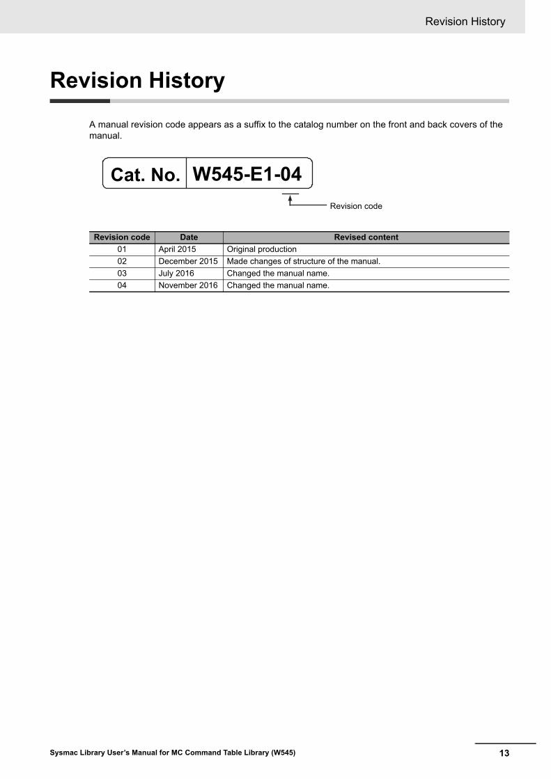
A manual revision code appears as a suffix to the catalog number on the front and back covers of the manual.
Revision code Date Revised content
01 April 2015 Original production
02 December 2015 Made changes of structure of the manual.
03 July 2016 Changed the manual name.
04 November 2016 Changed the manual name.
W545-E1-04Revision code
Cat. No.

Revision History
14 Sysmac Library User’s Manual for MC Command Table Library (W545)
15Sysmac Library User’s Manual for MC Command Table Library (W545)
Procedure to Use Sysmac Libraries
Procedure to Use Sysmac Libraries Installed Using the Installer
16 Sysmac Library User’s Manual for MC Command Table Library (W545)
Procedure to Use Sysmac Librar-ies Installed Using the Installer
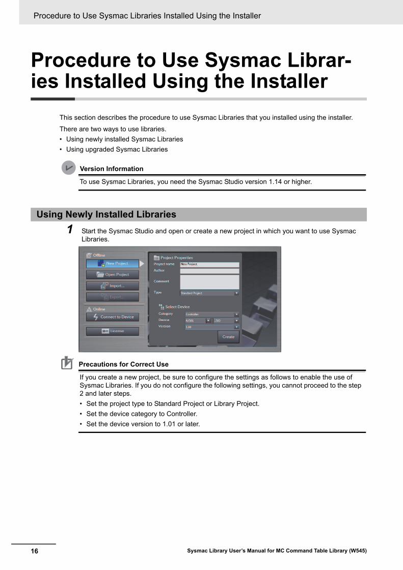
This section describes the procedure to use Sysmac Libraries that you installed using the installer.
There are two ways to use libraries.
• Using newly installed Sysmac Libraries
• Using upgraded Sysmac Libraries
Version Information
To use Sysmac Libraries, you need the Sysmac Studio version 1.14 or higher.
1 Start the Sysmac Studio and open or create a new project in which you want to use Sysmac Libraries.
Precautions for Correct Use
If you create a new project, be sure to configure the settings as follows to enable the use of Sysmac Libraries. If you do not configure the following settings, you cannot proceed to the step 2 and later steps.
• Set the project type to Standard Project or Library Project.
• Set the device category to Controller.
• Set the device version to 1.01 or later.
Using Newly Installed Libraries
17
Procedure to Use Sysmac Libraries Installed Using the Installer
Sysmac Library User’s Manual for MC Command Table Library (W545)
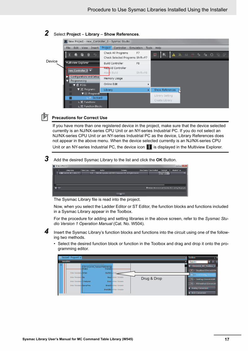
2 Select Project – Library – Show References.
Precautions for Correct Use
If you have more than one registered device in the project, make sure that the device selected currently is an NJ/NX-series CPU Unit or an NY-series Industrial PC. If you do not select an NJ/NX-series CPU Unit or an NY-series Industrial PC as the device, Library References does not appear in the above menu. When the device selected currently is an NJ/NX-series CPU
Unit or an NY-series Industrial PC, the device icon is displayed in the Multiview Explorer.
3 Add the desired Sysmac Library to the list and click the OK Button.
The Sysmac Library file is read into the project.
Now, when you select the Ladder Editor or ST Editor, the function blocks and functions included in a Sysmac Library appear in the Toolbox.
For the procedure for adding and setting libraries in the above screen, refer to the Sysmac Stu-dio Version 1 Operation Manual (Cat. No. W504).
4 Insert the Sysmac Library’s function blocks and functions into the circuit using one of the follow-ing two methods.
• Select the desired function block or function in the Toolbox and drag and drop it onto the pro-gramming editor.
Device
Drug & Drop
Procedure to Use Sysmac Libraries Installed Using the Installer
18 Sysmac Library User’s Manual for MC Command Table Library (W545)
• Right-click the programming editor, select Insert Function Block in the menu, and enter the fully qualified name (\\name of namespace\name of function block).
Precautions for Correct Use
After you upgrade the Sysmac Studio, check all programs and make sure that there is no error of the program check results on the Build Tab Page.
Select Project – Check All Programs from the Main Menu.
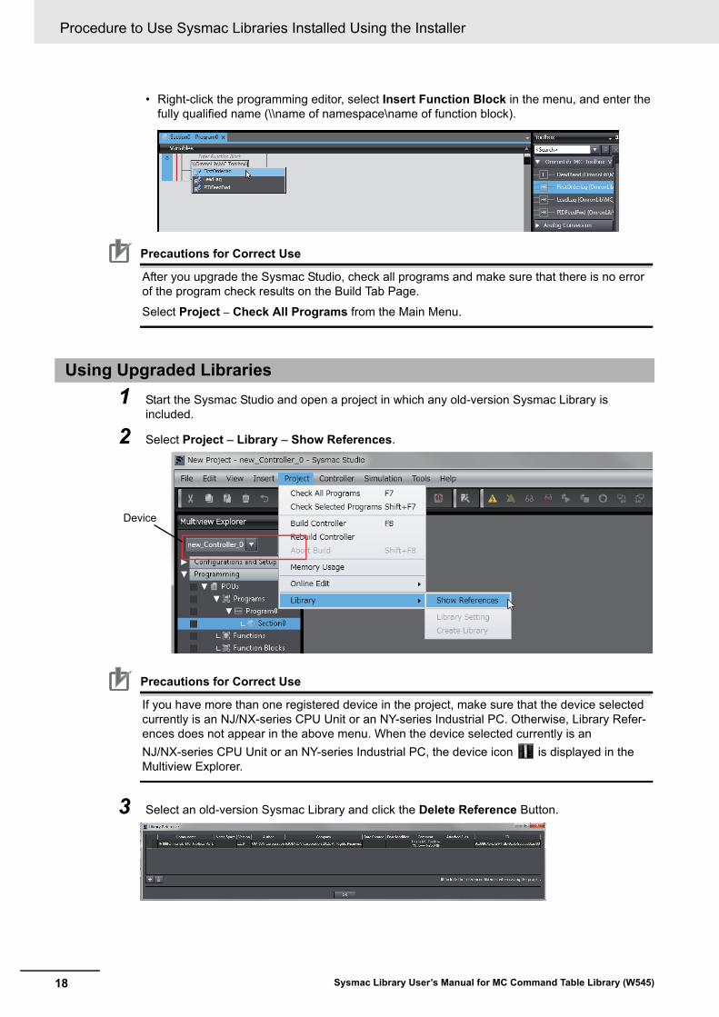
1 Start the Sysmac Studio and open a project in which any old-version Sysmac Library is included.
2 Select Project – Library – Show References.
Precautions for Correct Use
If you have more than one registered device in the project, make sure that the device selected currently is an NJ/NX-series CPU Unit or an NY-series Industrial PC. Otherwise, Library Refer-ences does not appear in the above menu. When the device selected currently is an
NJ/NX-series CPU Unit or an NY-series Industrial PC, the device icon is displayed in the Multiview Explorer.
3 Select an old-version Sysmac Library and click the Delete Reference Button.
Using Upgraded Libraries
Device
19
Procedure to Use Sysmac Libraries Installed Using the Installer
Sysmac Library User’s Manual for MC Command Table Library (W545)
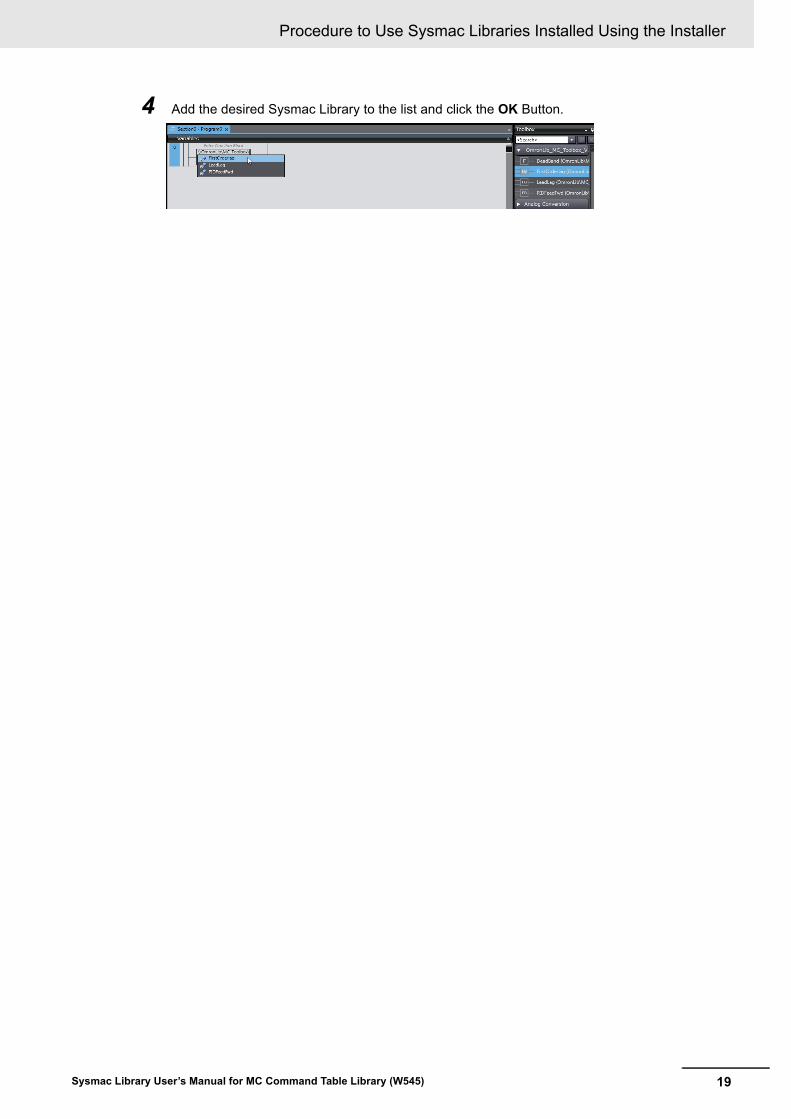
4 Add the desired Sysmac Library to the list and click the OK Button.
Procedure to Use Sysmac Libraries Uploaded from a CPU Unit or an Industrial PC
20 Sysmac Library User’s Manual for MC Command Table Library (W545)
Procedure to Use Sysmac Librar-ies Uploaded from a CPU Unit or an Industrial PC
You can use Sysmac Libraries uploaded from a CPU Unit or an Industrial PC to your computer if they are not installed.
The procedure to use uploaded Sysmac Libraries from a CPU Unit or an Industrial PC is as follows.
Version Information
To use Sysmac Libraries, you need the Sysmac Studio version 1.14 or higher.
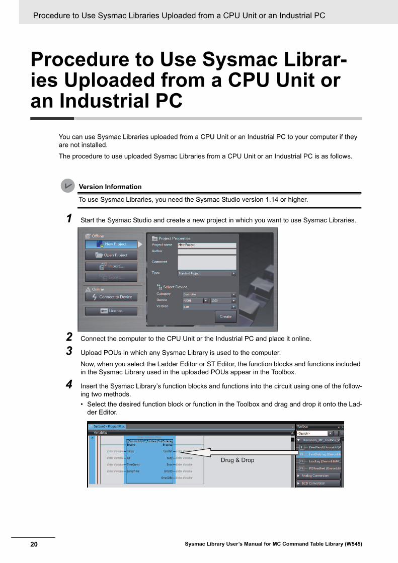
1 Start the Sysmac Studio and create a new project in which you want to use Sysmac Libraries.
2 Connect the computer to the CPU Unit or the Industrial PC and place it online.
3 Upload POUs in which any Sysmac Library is used to the computer.
Now, when you select the Ladder Editor or ST Editor, the function blocks and functions included in the Sysmac Library used in the uploaded POUs appear in the Toolbox.
4 Insert the Sysmac Library’s function blocks and functions into the circuit using one of the follow-ing two methods.
• Select the desired function block or function in the Toolbox and drag and drop it onto the Lad-der Editor.
Drug & Drop
21
Procedure to Use Sysmac Libraries Uploaded from a CPU Unit or an Industrial PC
Sysmac Library User’s Manual for MC Command Table Library (W545)
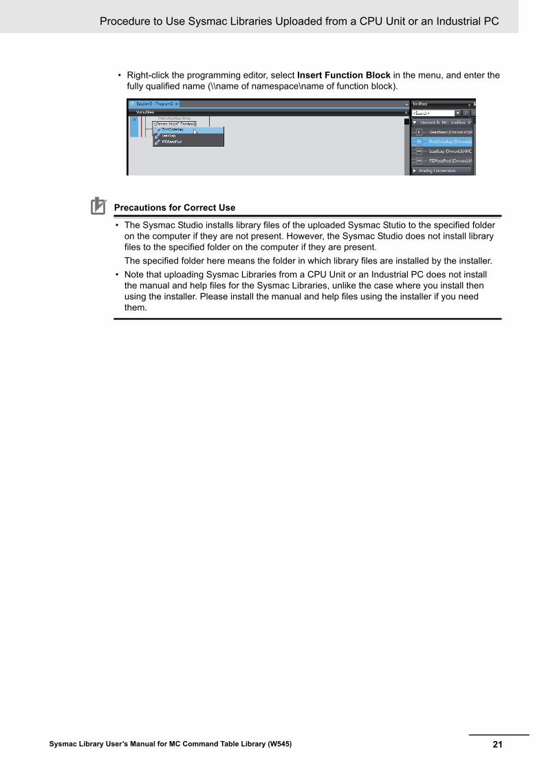
• Right-click the programming editor, select Insert Function Block in the menu, and enter the fully qualified name (\\name of namespace\name of function block).
Precautions for Correct Use
• The Sysmac Studio installs library files of the uploaded Sysmac Stutio to the specified folder on the computer if they are not present. However, the Sysmac Studio does not install library files to the specified folder on the computer if they are present.
The specified folder here means the folder in which library files are installed by the installer.
• Note that uploading Sysmac Libraries from a CPU Unit or an Industrial PC does not install the manual and help files for the Sysmac Libraries, unlike the case where you install then using the installer. Please install the manual and help files using the installer if you need them.
Procedure to Use Sysmac Libraries Uploaded from a CPU Unit or an Industrial PC
22 Sysmac Library User’s Manual for MC Command Table Library (W545)
23Sysmac Library User’s Manual for MC Command Table Library (W545)
Common Specifications of Function Blocks
Common Variables
24 Sysmac Library User’s Manual for MC Command Table Library (W545)
Common Variables
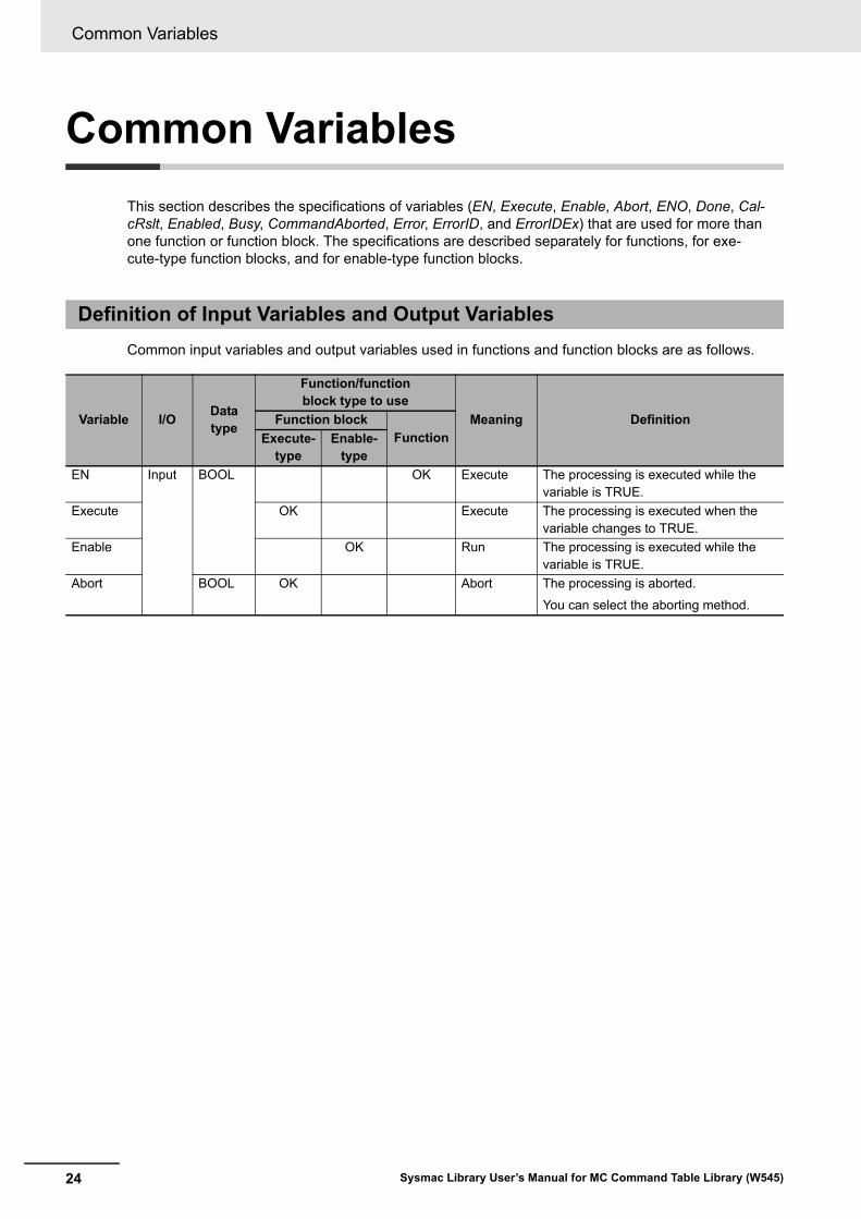
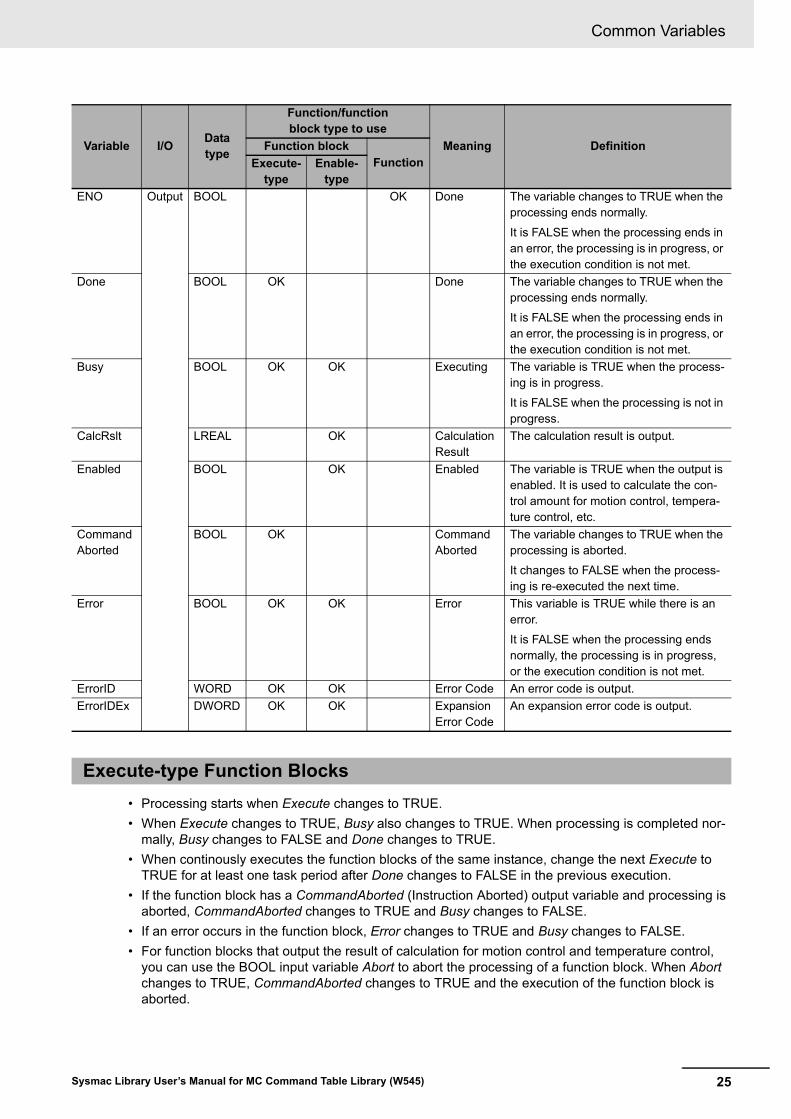
This section describes the specifications of variables (EN, Execute, Enable, Abort, ENO, Done, Cal-cRslt, Enabled, Busy, CommandAborted, Error, ErrorID, and ErrorIDEx) that are used for more than one function or function block. The specifications are described separately for functions, for exe-cute-type function blocks, and for enable-type function blocks.
Common input variables and output variables used in functions and function blocks are as follows.
Definition of Input Variables and Output Variables
Variable I/OData type
Function/function block type to use
Meaning DefinitionFunction blockFunctionExecute-
typeEnable-
type
EN Input BOOL OK Execute The processing is executed while the variable is TRUE.
Execute OK Execute The processing is executed when the variable changes to TRUE.
Enable OK Run The processing is executed while the variable is TRUE.
Abort BOOL OK Abort The processing is aborted.
You can select the aborting method.
25
Common Variables
Sysmac Library User’s Manual for MC Command Table Library (W545)
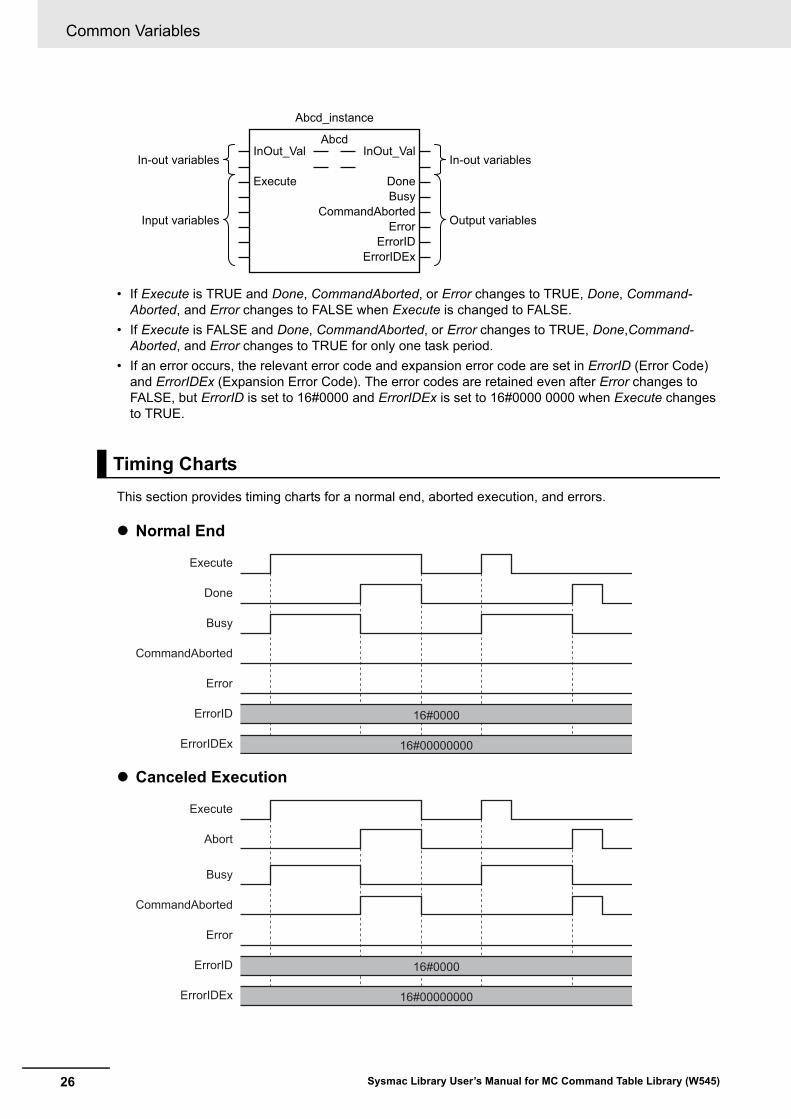
• Processing starts when Execute changes to TRUE.
• When Execute changes to TRUE, Busy also changes to TRUE. When processing is completed nor-mally, Busy changes to FALSE and Done changes to TRUE.
• When continously executes the function blocks of the same instance, change the next Execute to TRUE for at least one task period after Done changes to FALSE in the previous execution.
• If the function block has a CommandAborted (Instruction Aborted) output variable and processing is aborted, CommandAborted changes to TRUE and Busy changes to FALSE.
• If an error occurs in the function block, Error changes to TRUE and Busy changes to FALSE.
• For function blocks that output the result of calculation for motion control and temperature control, you can use the BOOL input variable Abort to abort the processing of a function block. When Abort changes to TRUE, CommandAborted changes to TRUE and the execution of the function block is aborted.
ENO Output BOOL OK Done The variable changes to TRUE when the processing ends normally.
It is FALSE when the processing ends in an error, the processing is in progress, or the execution condition is not met.
Done BOOL OK Done The variable changes to TRUE when the processing ends normally.
It is FALSE when the processing ends in an error, the processing is in progress, or the execution condition is not met.
Busy BOOL OK OK Executing The variable is TRUE when the process-ing is in progress.
It is FALSE when the processing is not in progress.
CalcRslt LREAL OK Calculation Result
The calculation result is output.
Enabled BOOL OK Enabled The variable is TRUE when the output is enabled. It is used to calculate the con-trol amount for motion control, tempera-ture control, etc.
Command Aborted
BOOL OK Command Aborted
The variable changes to TRUE when the processing is aborted.
It changes to FALSE when the process-ing is re-executed the next time.
Error BOOL OK OK Error This variable is TRUE while there is an error.
It is FALSE when the processing ends normally, the processing is in progress, or the execution condition is not met.
ErrorID WORD OK OK Error Code An error code is output.
ErrorIDEx DWORD OK OK Expansion Error Code
An expansion error code is output.
Execute-type Function Blocks
Variable I/OData type
Function/function block type to use
Meaning DefinitionFunction blockFunctionExecute-
typeEnable-
type
Common Variables
26 Sysmac Library User’s Manual for MC Command Table Library (W545)
• If Execute is TRUE and Done, CommandAborted, or Error changes to TRUE, Done, Command-Aborted, and Error changes to FALSE when Execute is changed to FALSE.
• If Execute is FALSE and Done, CommandAborted, or Error changes to TRUE, Done,Command-Aborted, and Error changes to TRUE for only one task period.
• If an error occurs, the relevant error code and expansion error code are set in ErrorID (Error Code) and ErrorIDEx (Expansion Error Code). The error codes are retained even after Error changes to FALSE, but ErrorID is set to 16#0000 and ErrorIDEx is set to 16#0000 0000 when Execute changes to TRUE.
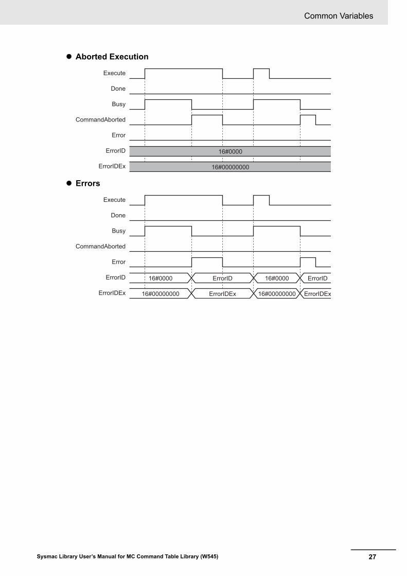
This section provides timing charts for a normal end, aborted execution, and errors.
Normal End
Canceled Execution
Timing Charts
In-out variables
Input variables
In-out variables
Output variables
Abcd_instance
InOut_Val InOut_Val
ErrorErrorID
ErrorIDEx
CommandAborted
Abcd
Execute DoneBusy
Busy
Done
CommandAborted
Error
16#00000000
16#0000ErrorID
ErrorIDEx
Execute
Busy
Abort
CommandAborted
Error
16#00000000
16#0000ErrorID
ErrorIDEx
Execute
27
Common Variables
Sysmac Library User’s Manual for MC Command Table Library (W545)
Aborted Execution
Errors
Busy
Done
CommandAborted
Error
16#00000000
16#0000ErrorID
ErrorIDEx
Execute
Busy
Done
CommandAborted
Error
16#0000 16#0000ErrorID
16#00000000 16#00000000ErrorIDEx ErrorIDExErrorIDEx
Execute
ErrorIDErrorIDErrorID ErrorID
Common Variables
28 Sysmac Library User’s Manual for MC Command Table Library (W545)
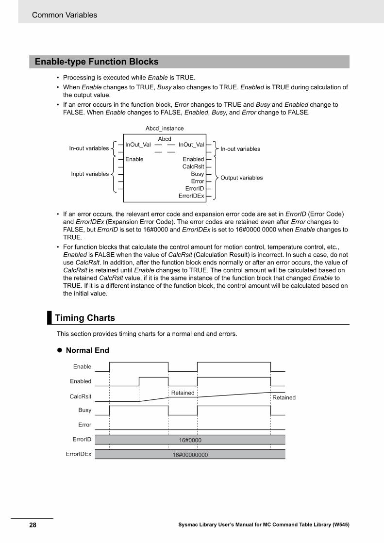
• Processing is executed while Enable is TRUE.
• When Enable changes to TRUE, Busy also changes to TRUE. Enabled is TRUE during calculation of the output value.
• If an error occurs in the function block, Error changes to TRUE and Busy and Enabled change to FALSE. When Enable changes to FALSE, Enabled, Busy, and Error change to FALSE.
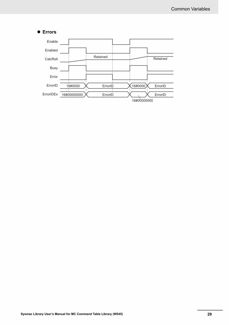
• If an error occurs, the relevant error code and expansion error code are set in ErrorID (Error Code) and ErrorIDEx (Expansion Error Code). The error codes are retained even after Error changes to FALSE, but ErrorID is set to 16#0000 and ErrorIDEx is set to 16#0000 0000 when Enable changes to TRUE.
• For function blocks that calculate the control amount for motion control, temperature control, etc., Enabled is FALSE when the value of CalcRslt (Calculation Result) is incorrect. In such a case, do not use CalcRslt. In addition, after the function block ends normally or after an error occurs, the value of CalcRslt is retained until Enable changes to TRUE. The control amount will be calculated based on the retained CalcRslt value, if it is the same instance of the function block that changed Enable to TRUE. If it is a different instance of the function block, the control amount will be calculated based on the initial value.
This section provides timing charts for a normal end and errors.
Normal End
Enable-type Function Blocks
Timing Charts
In-out variables
Input variables
In-out variables
Output variables
Abcd_instance
InOut_Val InOut_Val
BusyError
ErrorID
Abcd
Enable EnabledCalcRslt
ErrorIDEx
Busy
Enabled
Error
16#00000000
16#0000ErrorID
ErrorIDEx
Enable
CalcRslt RetainedRetained
29
Common Variables
Sysmac Library User’s Manual for MC Command Table Library (W545)
Errors
Busy
Enabled
Error
16#000016#0000 16#0000ErrorID
ErrorIDEx
Enable
ErrorIDErrorIDErrorID ErrorID
16#00000000
16#00000000
ErrorIDErrorIDErrorID ErrorID
16#0000
CalcRslt Retained Retained

Precautions
30 Sysmac Library User’s Manual for MC Command Table Library (W545)
Precautions
This section provides precautions for the use of this function block.
You can nest calls to this function block for up to four levels.
For details on nesting, refer to the software user’s manual.
You cannot use the upward differentiation option for this function block.
Execute-type function blocks cannot be re-executed by the same instance.
If you do so, the output value will be the initial value.
For details on re-execution, refer to the motion control user’s manual.
Nesting
Instruction Options
Re-execution of Function Blocks
31Sysmac Library User’s Manual for MC Command Table Library (W545)
Individual Specifications of Function Blocks
Function block name Name Page
MCCmdTbl Memory Operation P.32
MCCmdTbl
32 Sysmac Library User’s Manual for MC Command Table Library (W545)
MCCmdTbl
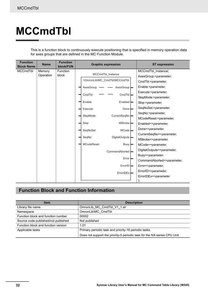
This is a function block to continuously execute positioning that is specified in memory operation data for axes groups that are defined in the MC Function Module.
Function Block Name
NameFunction
block/FUNGraphic expression ST expression
MCCmdTbl Memory Operation
Function block
MCCmdTbl_Instance(
AxesGroup:=parameter,
CmdTbl:=parameter,
Enable:=parameter,
Execute:=parameter,
StepMode:=parameter,
Stop:=parameter,
SeqNoSet:=parameter,
SeqNo:=parameter,
MCodeReset:=parameter,
Enabled=>parameter,
Done=>parameter,
CurrentSeqNo=>parameter,
MStrobe=>parameter,
MCode=>parameter,
DigitalOutputs=>parameter,
Busy=>parameter,
CommandAborted=>parameter,
Error=>parameter,
ErrorID=>parameter,
ErrorIDEx=>parameter);
Function Block and Function Information
Item Description
Library file name OmronLib_MC_CmdTbl_V1_1.slr
Namespace OmronLib\MC_CmdTbl
Function block and function number 00002
Source code published/not published Not published
Function block and function version 1.01
Applicable tasks Primary periodic task and priority-16 periodic tasks
Does not support the priority-5 periodic task for the NX-series CPU Unit.
\\OmronLib\MC_CmdTbl\MCCmdTbl
AxesGroup AxesGroup
CmdTbl CmdTbl
Enable Enabled
Execute Done
StepMode CurrentSeqNo
Stop MStrobe
SeqNoSet MCode
SeqNo DigitalOutputs
MCodeReset Busy
CommandAborted
Error
ErrorID
ErrorIDEx
MCCmdTbl_Instance
33
MCCmdTbl
Sysmac Library User’s Manual for MC Command Table Library (W545)
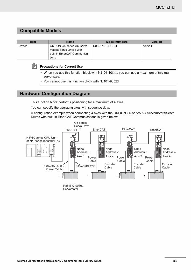
Precautions for Correct Use
• When you use this function block with NJ101-10, you can use a maximum of two real servo axes.
• You cannot use this function block with NJ101-90.
This function block performs positioning for a maximum of 4 axes.
You can specify the operating axes with sequence data.
A configuration example when connecting 4 axes with the OMRON G5-series AC Servomotors/Servo Drives with built-in EtherCAT Communications is given below.
Compatible Models
Item Name Model numbers Version
Device OMRON G5-series AC Servo-motors/Servo Drives with built-in EtherCAT Communica-tions
R88D-KN-ECT Ver.2.1
Hardware Configuration Diagram
G5-seriesServo Drive
NJ/NX-series CPU Unitor NY-series Industrial PC
R88M-K10030LServomotor
EtherCAT
R88A-CAKA003SPower Cable
Encoder Cable
Encoder Cable
Encoder Cable
EtherCAT
PowerCable
PowerCable
PowerCable
R88A-CRKA003C
Node Address 1Axis 1
Node Address 2Axis 2
Node Address 3Axis 3
Node Address 4Axis 4
EtherCAT EtherCAT
MCCmdTbl
34 Sysmac Library User’s Manual for MC Command Table Library (W545)
Variables
Input Variables
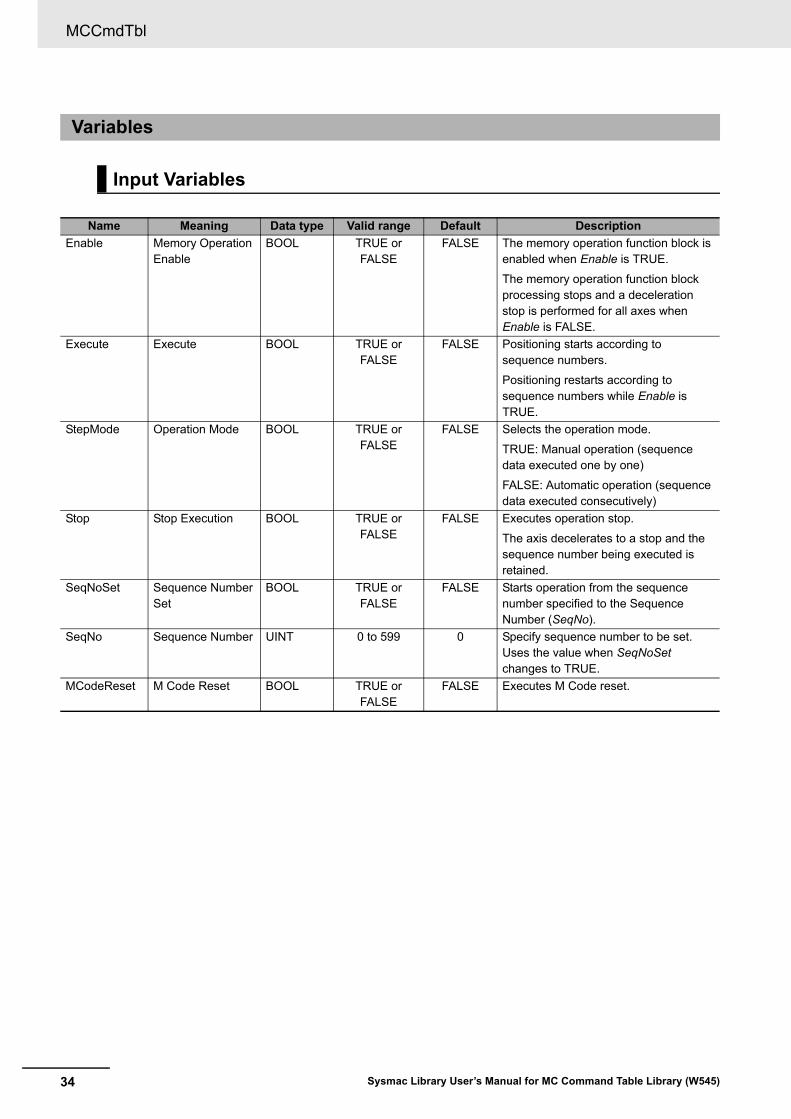
Name Meaning Data type Valid range Default Description
Enable Memory Operation Enable
BOOL TRUE or FALSE
FALSE The memory operation function block is enabled when Enable is TRUE.
The memory operation function block processing stops and a deceleration stop is performed for all axes when Enable is FALSE.
Execute Execute BOOL TRUE or FALSE
FALSE Positioning starts according to sequence numbers.
Positioning restarts according to sequence numbers while Enable is TRUE.
StepMode Operation Mode BOOL TRUE or FALSE
FALSE Selects the operation mode.
TRUE: Manual operation (sequence data executed one by one)
FALSE: Automatic operation (sequence data executed consecutively)
Stop Stop Execution BOOL TRUE or FALSE
FALSE Executes operation stop.
The axis decelerates to a stop and the sequence number being executed is retained.
SeqNoSet Sequence NumberSet
BOOL TRUE or FALSE
FALSE Starts operation from the sequence number specified to the Sequence Number (SeqNo).
SeqNo Sequence Number UINT 0 to 599 0 Specify sequence number to be set.Uses the value when SeqNoSet changes to TRUE.
MCodeReset M Code Reset BOOL TRUE or FALSE
FALSE Executes M Code reset.
35
MCCmdTbl
Sysmac Library User’s Manual for MC Command Table Library (W545)
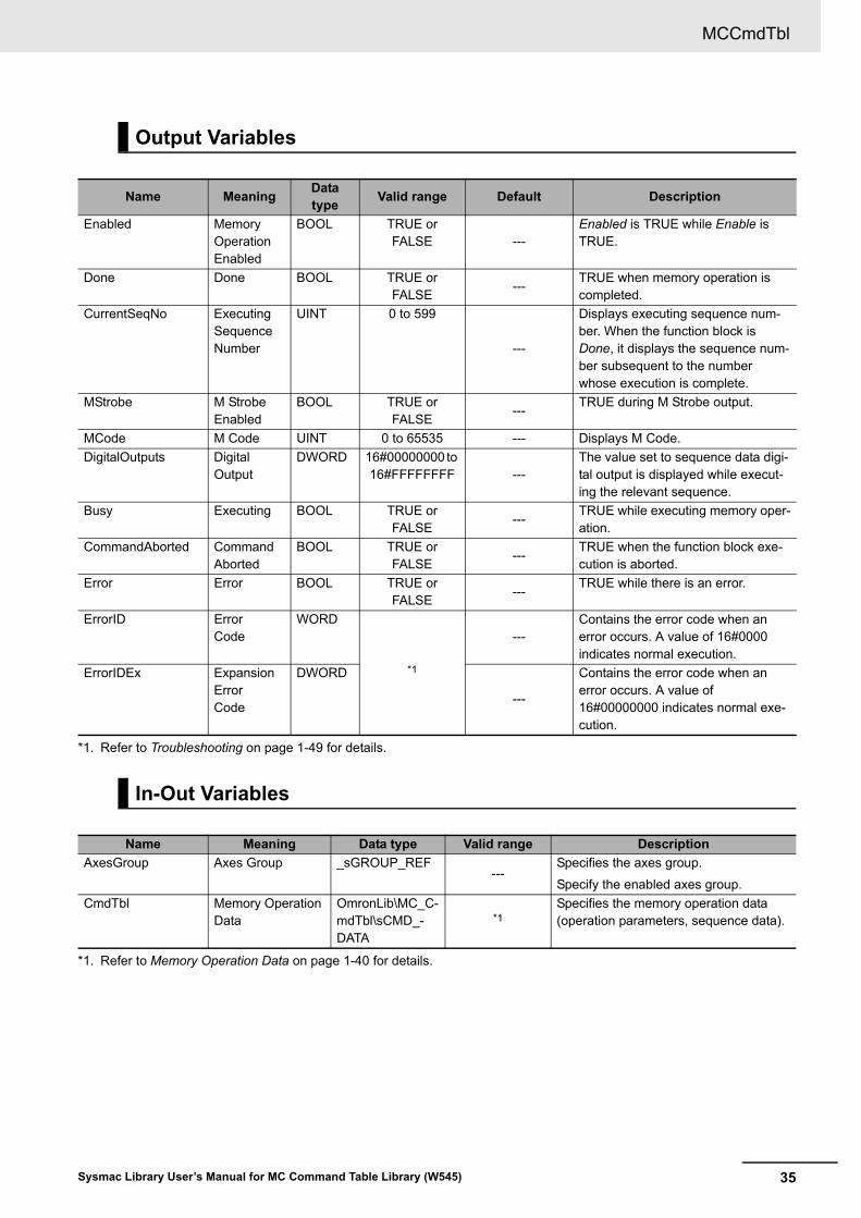
Output Variables
Name MeaningData type
Valid range Default Description
Enabled Memory Operation Enabled
BOOL TRUE or FALSE ---
Enabled is TRUE while Enable is TRUE.
Done Done BOOL TRUE or FALSE
---TRUE when memory operation is completed.
CurrentSeqNo Executing Sequence Number
UINT 0 to 599
---
Displays executing sequence num-ber. When the function block is Done, it displays the sequence num-ber subsequent to the number whose execution is complete.
MStrobe M Strobe Enabled
BOOL TRUE or FALSE
---TRUE during M Strobe output.
MCode M Code UINT 0 to 65535 --- Displays M Code.
DigitalOutputs DigitalOutput
DWORD 16#00000000 to 16#FFFFFFFF ---
The value set to sequence data digi-tal output is displayed while execut-ing the relevant sequence.
Busy Executing BOOL TRUE or FALSE
---TRUE while executing memory oper-ation.
CommandAborted Command Aborted
BOOL TRUE or FALSE
---TRUE when the function block exe-cution is aborted.
Error Error BOOL TRUE or FALSE
---TRUE while there is an error.
ErrorID ErrorCode
WORD
*1
*1. Refer to Troubleshooting on page 1-49 for details.
---Contains the error code when an error occurs. A value of 16#0000 indicates normal execution.
ErrorIDEx ExpansionErrorCode
DWORD
---
Contains the error code when an error occurs. A value of 16#00000000 indicates normal exe-cution.
In-Out Variables
Name Meaning Data type Valid range Description
AxesGroup Axes Group _sGROUP_REF---
Specifies the axes group.
Specify the enabled axes group.
CmdTbl Memory Operation Data
OmronLib\MC_C-mdTbl\sCMD_-DATA
*1
*1. Refer to Memory Operation Data on page 1-40 for details.
Specifies the memory operation data (operation parameters, sequence data).
MCCmdTbl
36 Sysmac Library User’s Manual for MC Command Table Library (W545)
This is a function block to continuously execute positioning that is specified in memory operation data for axes groups that are defined in the MC Function Module.
It performs the following functions.
• Automatic operation mode which executes sequence data consecutively
• Manual operation mode which executes sequence data one by one
• Setting the sequence number from which operation is started
• M Code output and M Code reset functions
• Stop function which stops operation
The following conditions must be met to execute the memory operation function block.
• Setting axes and axes groups
Use the Sysmac Studio to set the axes.
When you perform interpolation, set the axes group consisting of these axes.
• Creating memory operation data
Create operation parameters and sequence data.
Refer to Sample Programming on page 1-50 for a creation example of memory operation data.
• Assigning variables to the function block
Assign the created axes group variables, memory operation data variables, and other required vari-ables to the inputs and outputs variables of the memory operation function block.
• Servo ON and homing
Change the axes to control to the Servo ON status, and then define home.
Precautions for Correct Use
• When you execute the memory operation function block, check that the axes to control are in servo ON status and the home is defined. If these conditions are not met, a Memory Opera-tion Execution Error (error code: 16#3C09 and expansion error code: 16#00000001) will occur.
• The memory operation function block confirms servo ON status and home defined when started, but not after confirmation. If an error occurs in the MC Function Module due to these factors, an axis/axes group error (error code: 16#3C09 and expansion error code: 16#00000002) will occur in the function block.
Memory Operation Enable (Enable)
If you set Enable to TRUE and Enabled is TRUE, the commands of Execute and Stop will be enabled.
When Enable is FALSE, the commands will not be sent and the output variable will be initialized.
If you set Enable to FALSE during axis motion, the axes will decelerate to a stop following the exe-cuting command profile deceleration pattern.
Function
Execution Conditions
Details
37
MCCmdTbl
Sysmac Library User’s Manual for MC Command Table Library (W545)
Execute
When you set Execute to TRUE during Enabled, operation starts according to the content defined in sequence data SeqData (sSEQ_DATA type).
Operation Mode (StepMode)
This variable is used to switch the operation mode between automatic and manual operation.
The automatic operation mode executes sequence data consecutively.
The conditions to stop the automatic operation are given below.
• The END instruction execution
• The sequence data operation pattern is set to independent positioning.
• Stop execution
• Detection of an error or an interruption
The sequence number will return to 0 after the sequence number 599 is executed.
Conversely, the manual operation mode executes sequence data one by one.
When Execute changes to TRUE, the mode is defined according to the specified Operation Mode (StepMode). When you switch modes, set Execute to TRUE again after executing Stop.
Stop Execution (Stop)
If the operation stop is executed, the axis will decelerate to a stop in accordance with the decelera-tion time of the current memory operation data.
The MC_Stop instruction will be executed in the function block during PTP operation and the MC_GroupStop instruction is executed in the function block during interpolation operation.
When the axis stops, the instruction is interrupted and the executing sequence number is not updated.
In dwell time waiting status, the instruction goes to an interruption status without waiting for the dwell time.
If Stop is executed while the M code is output, the M code output changes to OFF and the instruc-tion is interrupted.
Precautions for Correct Use
• To decelerate an axis/axes group to a stop, set Stop to TRUE in the function block. For decel-eration stop during memory operation through function block execution, do not use the MC_Stop or MC_GroupStop instruction.
• If you perform an immediate stop for memory operation, execute the MC_ImmediateStop instruction for all axes being used in memory operation. Use the MC_GroupImmediateStop instruction to perform a multi-axes coordinated control motion.
• During a single-axis discrete motion, the axis will not stop even if you execute the MC_GroupImmediateStop instruction.
• During memory operation, make sure that the axes are in servo ON status at all times. When you set the servo to OFF during memory operation, set Enable to FALSE in the function block.
Sequence Number Set (SeqNoSet)
This variable is used to specify the sequence number from which to start operation.
Enter the sequence number from which you want to start operation into Sequence Number (SeqNo) and set SeqNoSet to TRUE.
When Execute changes to TRUE, operation is started from the entered sequence number.
MCCmdTbl
38 Sysmac Library User’s Manual for MC Command Table Library (W545)
Lookahead
When the lookahead conditions are met in automatic operation mode, next sequence data is read in advance and the operation starts in the pattern specified in the sequence data (SeqData) operation pattern (Ope).
Lookahead processing is executed when all the following conditions are met.
• The command currently executing is linear interpolation or circular interpolation
• The command for the next sequence data is linear interpolation or circular interpolation
• The command currently executing is not specified to dwell time
• The command currently executing is not specified to M Code
• The operation pattern is specified to either of the consecutive trajectories
If memory operation is interrupted during lookahead by a stop command, disabling the memory operation, or an error detected, the sequence data looked ahead to is discarded.
M Code Reset (MCodeReset)
While MStrobe (M Strobe Enabled) is TRUE, if you set MCodeReset (M Code Reset) to TRUE, MStrobe will be FALSE and the operation will move on to the next sequence number.
Precautions for Correct Use
• If you execute the MC_ImmediateStop or MC_ImmediateGroupStop instruction during M Code output, an error will occur in the function block and M Code output will stop.
• If you execute the MC_Stop or MC_GroupStop instruction during M Code output, the axis/axes group will start motion again after M Code reset. For a deceleration stop during memory operation, set Stop to TRUE in the function block, and do not use the MC_Stop or MC_GroupStop instruction.
Error End
When a motion control instruction error or an axis/axes group error is detected during memory oper-ation, the executing motion is interrupted and the function ends abnormally. As well, when during lookahead, the sequence data looked ahead to is discarded. The executing sequence number is not updated.
Operation Restart
• When you restart memory operation, change Enable to TRUE, enter the sequence number from which you want to restart into SeqNo, set Execute to TRUE when SeqNoSet is TRUE.
• If an error occurs in an axis/axes group, restart memory operation after clearing the error.
• If an undefined home error occurs, restart memory operation after clearing the error and defining home.
Precautions for Correct Use
When you stop memory operation and then restart it again, retain CurrentSeqNo (Executing Sequence Number) in order to start from the sequence number at which memory operation was stopped.
39
MCCmdTbl
Sysmac Library User’s Manual for MC Command Table Library (W545)
This function block cannot be re-executed.
In this function block, a re-execution refers to setting Execute to TRUE again during axis motion by exe-cuting this function block.
A restriction applies to the instructions that can be used while this function block is in execution.
The MC_Move, MC_MoveLinear, and MC_MoveCircular2D motion control instructions are used in this function block so that multi-execution of instructions depends on the specifications of these instruc-tions.
For details, refer to the CPU Unit motion control user's Manual.
Precautions for Correct Use
• For a deceleration stop during memory operation, do not use the MC_Stop or MC_Group-Stop instruction.
• For a immediate stop during memory operation, use the MC_ImmediateStop and MC_Imme-diateGroupStop instructions.
• During memory operation, do not perform the multi-execution of instructions regarding the axis/axes group used for memory operation.
Additional Information
When you execute the MC_SetOverride and MC_GroupSetOverride instructions during mem-ory operation, check the effect of overriding the target velocity before use.
Re-execution of Instruction
Multi-execution of Instructions
MCCmdTbl
40 Sysmac Library User’s Manual for MC Command Table Library (W545)
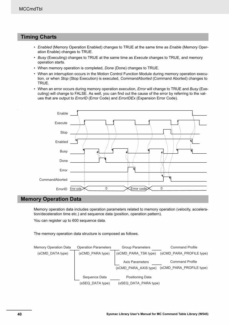
• Enabled (Memory Operation Enabled) changes to TRUE at the same time as Enable (Memory Oper-ation Enable) changes to TRUE.
• Busy (Executing) changes to TRUE at the same time as Execute changes to TRUE, and memory operation starts.
• When memory operation is completed, Done (Done) changes to TRUE.
• When an interruption occurs in the Motion Control Function Module during memory operation execu-tion, or when Stop (Stop Execution) is executed, CommandAborted (Command Aborted) changes to TRUE.
• When an error occurs during memory operation execution, Error will change to TRUE and Busy (Exe-cuting) will change to FALSE. As well, you can find out the cause of the error by referring to the val-ues that are output to ErrorID (Error Code) and ErrorIDEx (Expansion Error Code).
?
Memory operation data includes operation parameters related to memory operation (velocity, accelera-tion/deceleration time etc.) and sequence data (position, operation pattern).
You can register up to 600 sequence data.
The memory operation data structure is composed as follows.
Timing Charts
Memory Operation Data
Enable
Execute
Stop
Enabled
Busy
Done
Error
ErrorID 0 0
CommandAborted
Error codeError code
Memory Operation Data
(sCMD_DATA type)
Operation Parameters
(sCMD_PARA type)
Sequence Data
(sSEQ_DATA type)
Group Parameters
(sCMD_PARA_TSK type)
Axis Parameters
(sCMD_PARA_AXIS type)
Command Profile
(sCMD_PARA_PROFILE type)
Command Profile
(sCMD_PARA_PROFILE type)
Positioning Data
(sSEQ_DATA_PARA type)
41
MCCmdTbl
Sysmac Library User’s Manual for MC Command Table Library (W545)
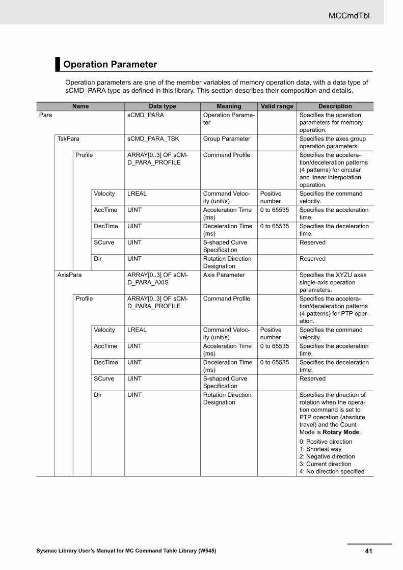
Operation parameters are one of the member variables of memory operation data, with a data type of sCMD_PARA type as defined in this library. This section describes their composition and details.
Operation Parameter
Name Data type Meaning Valid range Description
Para sCMD_PARA Operation Parame-ter
Specifies the operation parameters for memory operation.
TskPara sCMD_PARA_TSK Group Parameter Specifies the axes group operation parameters.
Profile ARRAY[0..3] OF sCM-D_PARA_PROFILE
Command Profile Specifies the accelera-tion/deceleration patterns (4 patterns) for circular and linear interpolation operation.
Velocity LREAL Command Veloc-ity (unit/s)
Positive number
Specifies the command velocity.
AccTime UINT Acceleration Time (ms)
0 to 65535 Specifies the acceleration time.
DecTime UINT Deceleration Time (ms)
0 to 65535 Specifies the deceleration time.
SCurve UINT S-shaped Curve Specification
Reserved
Dir UINT Rotation Direction Designation
Reserved
AxisPara ARRAY[0..3] OF sCM-D_PARA_AXIS
Axis Parameter Specifies the XYZU axes single-axis operation parameters.
Profile ARRAY[0..3] OF sCM-D_PARA_PROFILE
Command Profile Specifies the accelera-tion/deceleration patterns (4 patterns) for PTP oper-ation.
Velocity LREAL Command Veloc-ity (unit/s)
Positive number
Specifies the command velocity.
AccTime UINT Acceleration Time (ms)
0 to 65535 Specifies the acceleration time.
DecTime UINT Deceleration Time (ms)
0 to 65535 Specifies the deceleration time.
SCurve UINT S-shaped Curve Specification
Reserved
Dir UINT Rotation Direction Designation
Specifies the direction of rotation when the opera-tion command is set to PTP operation (absolute travel) and the Count Mode is Rotary Mode.
0: Positive direction1: Shortest way2: Negative direction3: Current direction4: No direction specified
MCCmdTbl
42 Sysmac Library User’s Manual for MC Command Table Library (W545)
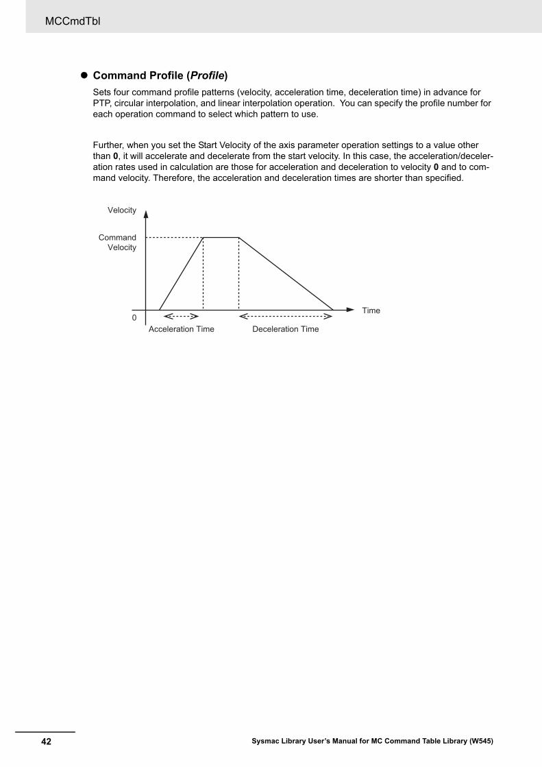
Command Profile (Profile)
Sets four command profile patterns (velocity, acceleration time, deceleration time) in advance for PTP, circular interpolation, and linear interpolation operation. You can specify the profile number for each operation command to select which pattern to use.
Further, when you set the Start Velocity of the axis parameter operation settings to a value other than 0, it will accelerate and decelerate from the start velocity. In this case, the acceleration/deceler-ation rates used in calculation are those for acceleration and deceleration to velocity 0 and to com-mand velocity. Therefore, the acceleration and deceleration times are shorter than specified.
0
Velocity
Time
Acceleration Time Deceleration Time
Command Velocity
43
MCCmdTbl
Sysmac Library User’s Manual for MC Command Table Library (W545)
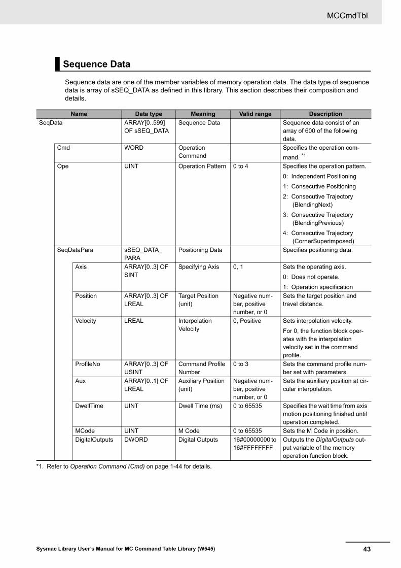
Sequence data are one of the member variables of memory operation data. The data type of sequence data is array of sSEQ_DATA as defined in this library. This section describes their composition and details.
Sequence Data
Name Data type Meaning Valid range Description
SeqData ARRAY[0..599] OF sSEQ_DATA
Sequence Data Sequence data consist of an array of 600 of the following data.
Cmd WORD Operation Command
Specifies the operation com-
mand. *1
*1. Refer to Operation Command (Cmd) on page 1-44 for details.
Ope UINT Operation Pattern 0 to 4 Specifies the operation pattern.
0: Independent Positioning
1: Consecutive Positioning
2: Consecutive Trajectory (BlendingNext)
3: Consecutive Trajectory (BlendingPrevious)
4: Consecutive Trajectory (CornerSuperimposed)
SeqDataPara sSEQ_DATA_PARA
Positioning Data Specifies positioning data.
Axis ARRAY[0..3] OF SINT
Specifying Axis 0, 1 Sets the operating axis.
0: Does not operate.
1: Operation specification
Position ARRAY[0..3] OF LREAL
Target Position (unit)
Negative num-ber, positive number, or 0
Sets the target position and travel distance.
Velocity LREAL Interpolation Velocity
0, Positive Sets interpolation velocity.
For 0, the function block oper-ates with the interpolation velocity set in the command profile.
ProfileNo ARRAY[0..3] OF USINT
Command Profile Number
0 to 3 Sets the command profile num-ber set with parameters.
Aux ARRAY[0..1] OF LREAL
Auxiliary Position (unit)
Negative num-ber, positive number, or 0
Sets the auxiliary position at cir-cular interpolation.
DwellTime UINT Dwell Time (ms) 0 to 65535 Specifies the wait time from axis motion positioning finished until operation completed.
MCode UINT M Code 0 to 65535 Sets the M Code in position.
DigitalOutputs DWORD Digital Outputs 16#00000000 to 16#FFFFFFFF
Outputs the DigitalOutputs out-put variable of the memory operation function block.
MCCmdTbl
44 Sysmac Library User’s Manual for MC Command Table Library (W545)
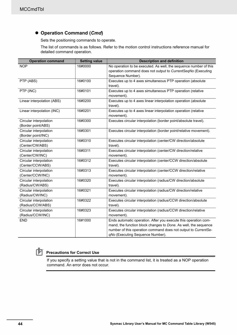
Operation Command (Cmd)
Sets the positioning commands to operate.
The list of commands is as follows. Refer to the motion control instructions reference manual for detailed command operation.
Precautions for Correct Use
If you specify a setting value that is not in the command list, it is treated as a NOP operation command. An error does not occur.
Operation command Setting value Description and definition
NOP 16#0000 No operation to be executed. As well, the sequence number of this operation command does not output to CurrentSeqNo (Executing Sequence Number).
PTP (ABS) 16#0100 Executes up to 4 axes simultaneous PTP operation (absolute travel).
PTP (INC) 16#0101 Executes up to 4 axes simultaneous PTP operation (relative movement).
Linear interpolation (ABS) 16#0200 Executes up to 4 axes linear interpolation operation (absolute travel).
Linear interpolation (INC) 16#0201 Executes up to 4 axes linear interpolation operation (relative movement).
Circular interpolation (Border point/ABS)
16#0300 Executes circular interpolation (border point/absolute travel).
Circular interpolation (Border point/INC)
16#0301 Executes circular interpolation (border point/relative movement).
Circular interpolation (Center/CW/ABS)
16#0310 Executes circular interpolation (center/CW direction/absolute travel).
Circular interpolation (Center/CW/INC)
16#0311 Executes circular interpolation (center/CW direction/relative movement).
Circular interpolation (Center/CCW/ABS)
16#0312 Executes circular interpolation (center/CCW direction/absolute travel).
Circular interpolation (Center/CCW/INC)
16#0313 Executes circular interpolation (center/CCW direction/relative movement).
Circular interpolation (Radius/CW/ABS)
16#0320 Executes circular interpolation (radius/CW direction/absolute travel).
Circular interpolation (Radius/CW/INC)
16#0321 Executes circular interpolation (radius/CW direction/relative movement).
Circular interpolation (Radius/CCW/ABS)
16#0322 Executes circular interpolation (radius/CCW direction/absolute travel).
Circular interpolation (Radius/CCW/INC)
16#0323 Executes circular interpolation (radius/CCW direction/relative movement).
END 16#1000 Ends automatic operation. After you execute this operation com-mand, the function block changes to Done. As well, the sequence number of this operation command does not output to CurrentSe-qNo (Executing Sequence Number).
45
MCCmdTbl
Sysmac Library User’s Manual for MC Command Table Library (W545)
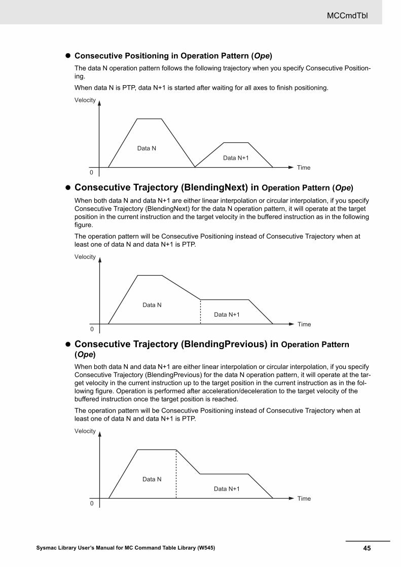
Consecutive Positioning in Operation Pattern (Ope)
The data N operation pattern follows the following trajectory when you specify Consecutive Position-ing.
When data N is PTP, data N+1 is started after waiting for all axes to finish positioning.
Consecutive Trajectory (BlendingNext) in Operation Pattern (Ope)
When both data N and data N+1 are either linear interpolation or circular interpolation, if you specify Consecutive Trajectory (BlendingNext) for the data N operation pattern, it will operate at the target position in the current instruction and the target velocity in the buffered instruction as in the following figure.
The operation pattern will be Consecutive Positioning instead of Consecutive Trajectory when at least one of data N and data N+1 is PTP.
Consecutive Trajectory (BlendingPrevious) in Operation Pattern (Ope)
When both data N and data N+1 are either linear interpolation or circular interpolation, if you specify Consecutive Trajectory (BlendingPrevious) for the data N operation pattern, it will operate at the tar-get velocity in the current instruction up to the target position in the current instruction as in the fol-lowing figure. Operation is performed after acceleration/deceleration to the target velocity of the buffered instruction once the target position is reached.
The operation pattern will be Consecutive Positioning instead of Consecutive Trajectory when at least one of data N and data N+1 is PTP.
0
Velocity
Time
Data NData N+1
Data NData N+1
0
Velocity
Time
Data NData N+1
0
Velocity
Time
MCCmdTbl
46 Sysmac Library User’s Manual for MC Command Table Library (W545)
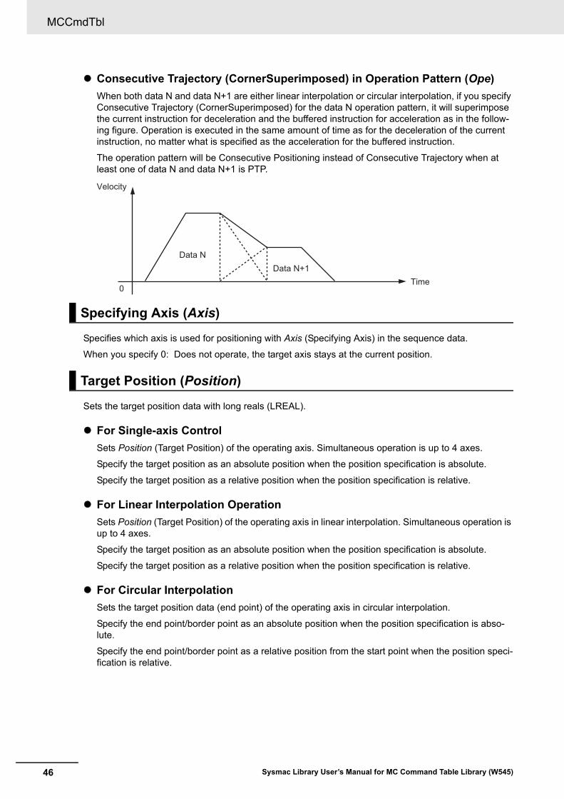
Consecutive Trajectory (CornerSuperimposed) in Operation Pattern (Ope)
When both data N and data N+1 are either linear interpolation or circular interpolation, if you specify Consecutive Trajectory (CornerSuperimposed) for the data N operation pattern, it will superimpose the current instruction for deceleration and the buffered instruction for acceleration as in the follow-ing figure. Operation is executed in the same amount of time as for the deceleration of the current instruction, no matter what is specified as the acceleration for the buffered instruction.
The operation pattern will be Consecutive Positioning instead of Consecutive Trajectory when at least one of data N and data N+1 is PTP.
Specifies which axis is used for positioning with Axis (Specifying Axis) in the sequence data.
When you specify 0: Does not operate, the target axis stays at the current position.
Sets the target position data with long reals (LREAL).
For Single-axis Control
Sets Position (Target Position) of the operating axis. Simultaneous operation is up to 4 axes.
Specify the target position as an absolute position when the position specification is absolute.
Specify the target position as a relative position when the position specification is relative.
For Linear Interpolation Operation
Sets Position (Target Position) of the operating axis in linear interpolation. Simultaneous operation is up to 4 axes.
Specify the target position as an absolute position when the position specification is absolute.
Specify the target position as a relative position when the position specification is relative.
For Circular Interpolation
Sets the target position data (end point) of the operating axis in circular interpolation.
Specify the end point/border point as an absolute position when the position specification is abso-lute.
Specify the end point/border point as a relative position from the start point when the position speci-fication is relative.
Specifying Axis (Axis)
Target Position (Position)
Data NData N+1
0
Velocity
Time
47
MCCmdTbl
Sysmac Library User’s Manual for MC Command Table Library (W545)
Sets the interpolation velocity for linear and circular interpolations. Do not use this variable for PTP.
When you set the interpolation velocity to 0.0, the velocity specified in the command profile is treated as interpolation velocity.
Specifies the command profile pattern with parameters set to PTP, linear interpolation, and circular interpolation.
The command profile pattern for each axis is used for PTP operation.
The command profile pattern for a group is used for linear and circular interpolation operation.
Sets the auxiliary position for circular interpolation.
• When you select the center, set Auxiliary Position 1 (Aux[0]) to center X coordinates and Auxiliary Position 2 (Aux[1]) to center Y coordinates.
• When you select the border point, set Auxiliary Position 1 (Aux[0]) to border point X coordinates and Auxiliary Position 2 (Aux[1]) to border point Y coordinates.
• When you select the radius, set Auxiliary Position 1 (Aux[0]) to arc radius.
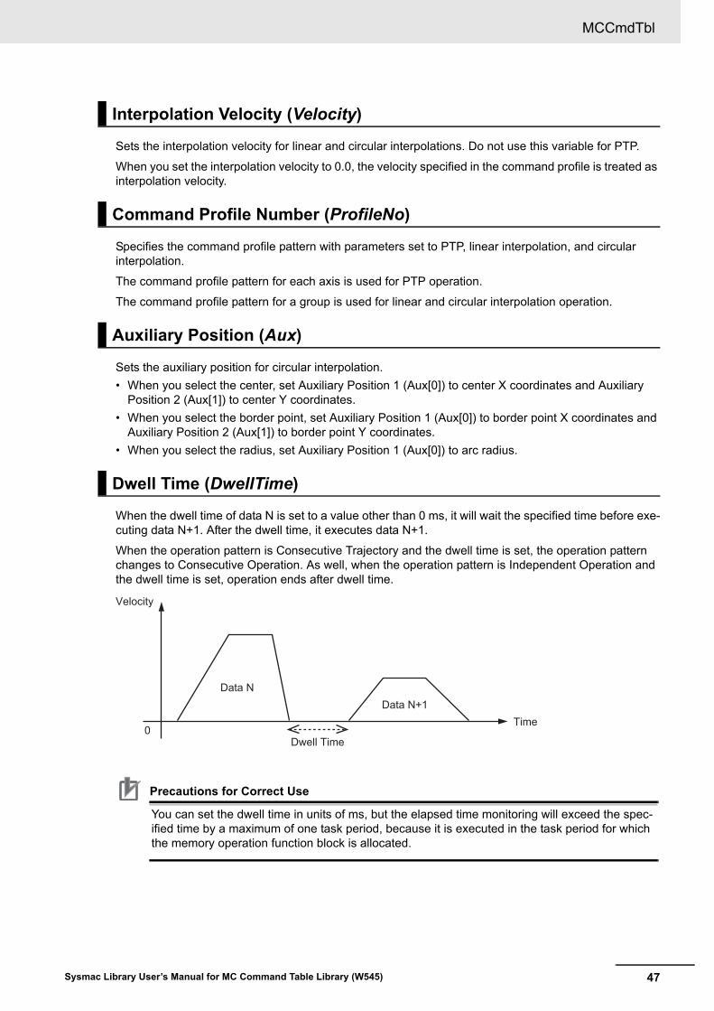
When the dwell time of data N is set to a value other than 0 ms, it will wait the specified time before exe-cuting data N+1. After the dwell time, it executes data N+1.
When the operation pattern is Consecutive Trajectory and the dwell time is set, the operation pattern changes to Consecutive Operation. As well, when the operation pattern is Independent Operation and the dwell time is set, operation ends after dwell time.
Precautions for Correct Use
You can set the dwell time in units of ms, but the elapsed time monitoring will exceed the spec-ified time by a maximum of one task period, because it is executed in the task period for which the memory operation function block is allocated.
Interpolation Velocity (Velocity)
Command Profile Number (ProfileNo)
Auxiliary Position (Aux)
Dwell Time (DwellTime)
Data NData N+1
Dwell Time0
Velocity
Time
MCCmdTbl
48 Sysmac Library User’s Manual for MC Command Table Library (W545)
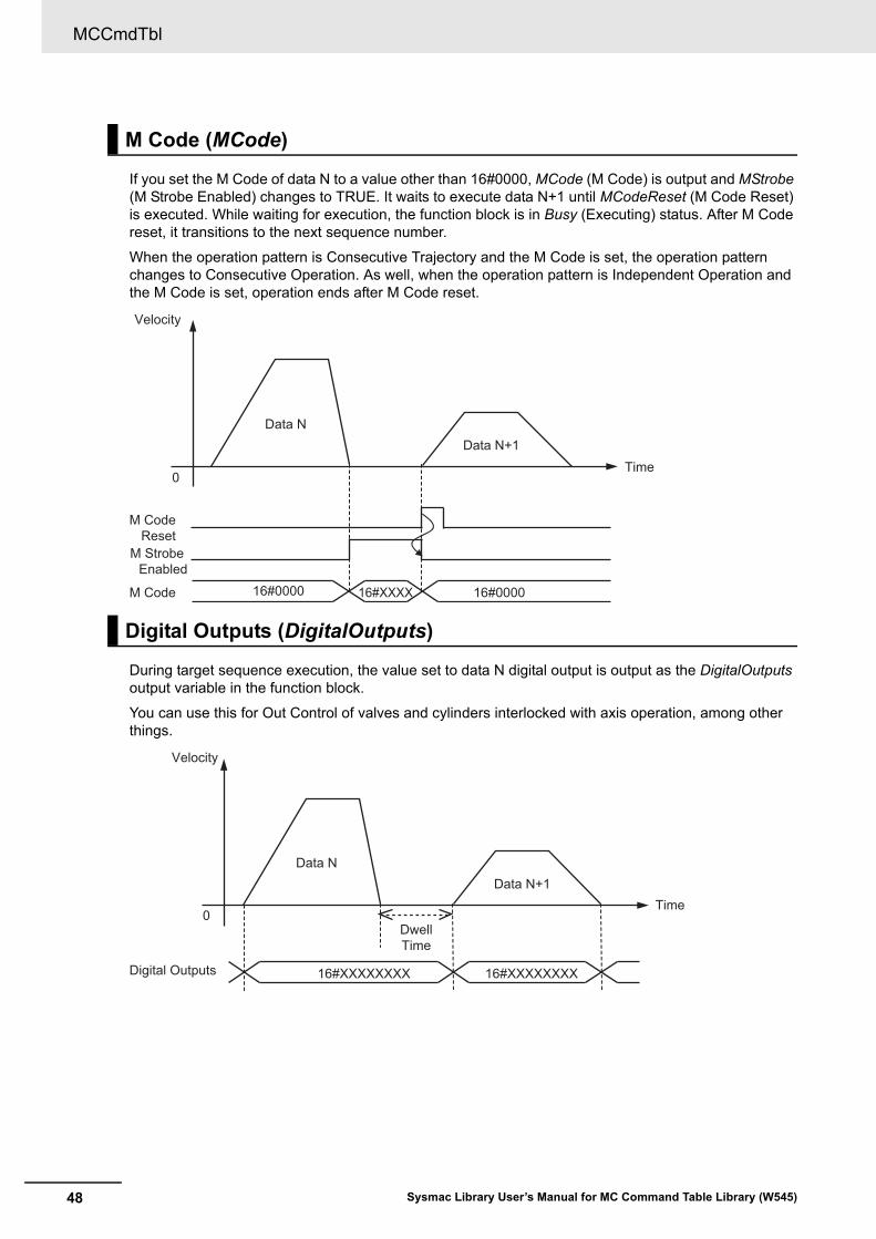
If you set the M Code of data N to a value other than 16#0000, MCode (M Code) is output and MStrobe (M Strobe Enabled) changes to TRUE. It waits to execute data N+1 until MCodeReset (M Code Reset) is executed. While waiting for execution, the function block is in Busy (Executing) status. After M Code reset, it transitions to the next sequence number.
When the operation pattern is Consecutive Trajectory and the M Code is set, the operation pattern changes to Consecutive Operation. As well, when the operation pattern is Independent Operation and the M Code is set, operation ends after M Code reset.
During target sequence execution, the value set to data N digital output is output as the DigitalOutputs output variable in the function block.
You can use this for Out Control of valves and cylinders interlocked with axis operation, among other things.
M Code (MCode)
Digital Outputs (DigitalOutputs)
Data NData N+1
M CodeReset
M Strobe Enabled
M Code 16#0000 16#000016#XXXX
0
Velocity
Time
0
Velocity
Time
Data NData N+1
Digital Outputs 16#XXXXXXXX
DwellTime
16#XXXXXXXX
49
MCCmdTbl
Sysmac Library User’s Manual for MC Command Table Library (W545)
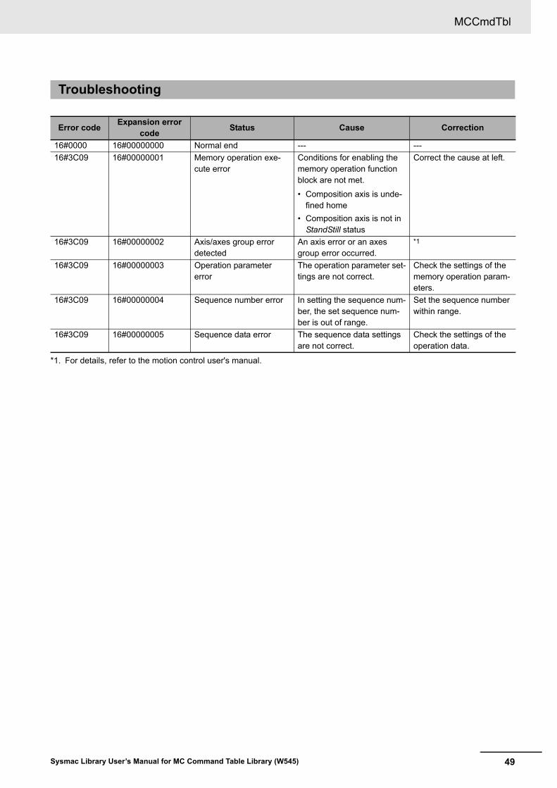
Troubleshooting
Error codeExpansion error
codeStatus Cause Correction
16#0000 16#00000000 Normal end --- ---
16#3C09 16#00000001 Memory operation exe-cute error
Conditions for enabling the memory operation function block are not met.
• Composition axis is unde-fined home
• Composition axis is not in StandStill status
Correct the cause at left.
16#3C09 16#00000002 Axis/axes group error detected
An axis error or an axes group error occurred.
*1
*1. For details, refer to the motion control user's manual.
16#3C09 16#00000003 Operation parameter error
The operation parameter set-tings are not correct.
Check the settings of the memory operation param-eters.
16#3C09 16#00000004 Sequence number error In setting the sequence num-ber, the set sequence num-ber is out of range.
Set the sequence number within range.
16#3C09 16#00000005 Sequence data error The sequence data settings are not correct.
Check the settings of the operation data.
MCCmdTbl
50 Sysmac Library User’s Manual for MC Command Table Library (W545)
The sample programming below is implemented to execute the memory operation function block for the hardware configuration that is given in Hardware Configuration Diagram on page 1-33.
Control contents are set with sequence data.
Precautions for Correct Use
• The sample programming shows only the portion of a program that uses the function or func-tion block from the library.
• When using actual devices, also program safety circuits, device interlocks, I/O with other devices, and other control procedures.
• Create a user program that will produce the intended device operation.
• Check the user program for proper execution before you use it for actual operation.
• When you execute the memory operation function block, confirm the axis settings, axes group settings, memory operation data, and user program. As well, implement an external emergency stop circuit so that you can stop the motor safely if needed.
Additional Information
• This function block has four levels of interior function block nesting. The depth of the nesting levels is limited by the CPU Unit version or the Industrial PC version. When you nest this function block, refer to the software user's manual to confirm the depth limits on nesting lev-els.
• The Name space OmronLib\MC_CmdTbl is set for the memory operation function block and the data type of memory operation data. Declare and use namespace with reference to the software user's manual.
The sample performs processes in the following order.
1 When you set Start to TRUE, the control targets (4 axes) execute servo ON and homing.
2 When servo is ON and home is completed, Ready changes to TRUE.
3 If Ready is not TRUE and the function block is not in Immediate Stop status, set Enable to TRUE.
4 Execute memory operation by setting Execute to TRUE.
5 If an immediate stop event occurs, execute the MC_GroupImmediateStop instruction and, for each axis, the MC_ImmediateStop instruction.
Sample Programming
51
MCCmdTbl
Sysmac Library User’s Manual for MC Command Table Library (W545)
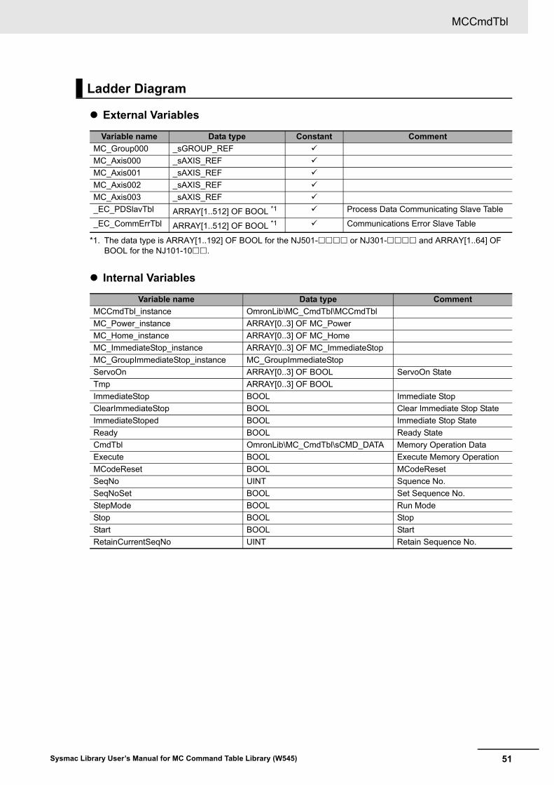
External Variables
Internal Variables
Ladder Diagram
Variable name Data type Constant Comment
MC_Group000 _sGROUP_REF
MC_Axis000 _sAXIS_REF
MC_Axis001 _sAXIS_REF
MC_Axis002 _sAXIS_REF
MC_Axis003 _sAXIS_REF
_EC_PDSlavTbl ARRAY[1..512] OF BOOL *1
*1. The data type is ARRAY[1..192] OF BOOL for the NJ501- or NJ301- and ARRAY[1..64] OF BOOL for the NJ101-10.
Process Data Communicating Slave Table
_EC_CommErrTbl ARRAY[1..512] OF BOOL *1 Communications Error Slave Table
Variable name Data type Comment
MCCmdTbl_instance OmronLib\MC_CmdTbl\MCCmdTbl
MC_Power_instance ARRAY[0..3] OF MC_Power
MC_Home_instance ARRAY[0..3] OF MC_Home
MC_ImmediateStop_instance ARRAY[0..3] OF MC_ImmediateStop
MC_GroupImmediateStop_instance MC_GroupImmediateStop
ServoOn ARRAY[0..3] OF BOOL ServoOn State
Tmp ARRAY[0..3] OF BOOL
ImmediateStop BOOL Immediate Stop
ClearImmediateStop BOOL Clear Immediate Stop State
ImmediateStoped BOOL Immediate Stop State
Ready BOOL Ready State
CmdTbl OmronLib\MC_CmdTbl\sCMD_DATA Memory Operation Data
Execute BOOL Execute Memory Operation
MCodeReset BOOL MCodeReset
SeqNo UINT Squence No.
SeqNoSet BOOL Set Sequence No.
StepMode BOOL Run Mode
Stop BOOL Stop
Start BOOL Start
RetainCurrentSeqNo UINT Retain Sequence No.
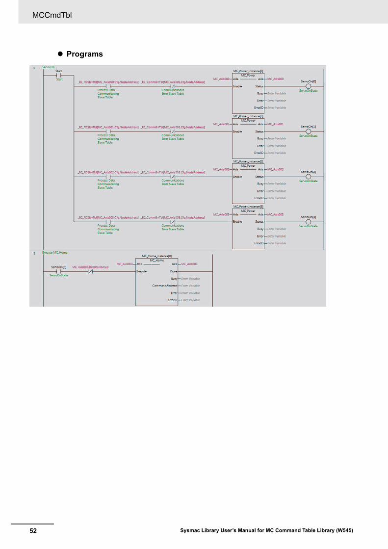
MCCmdTbl
52 Sysmac Library User’s Manual for MC Command Table Library (W545)
Programs
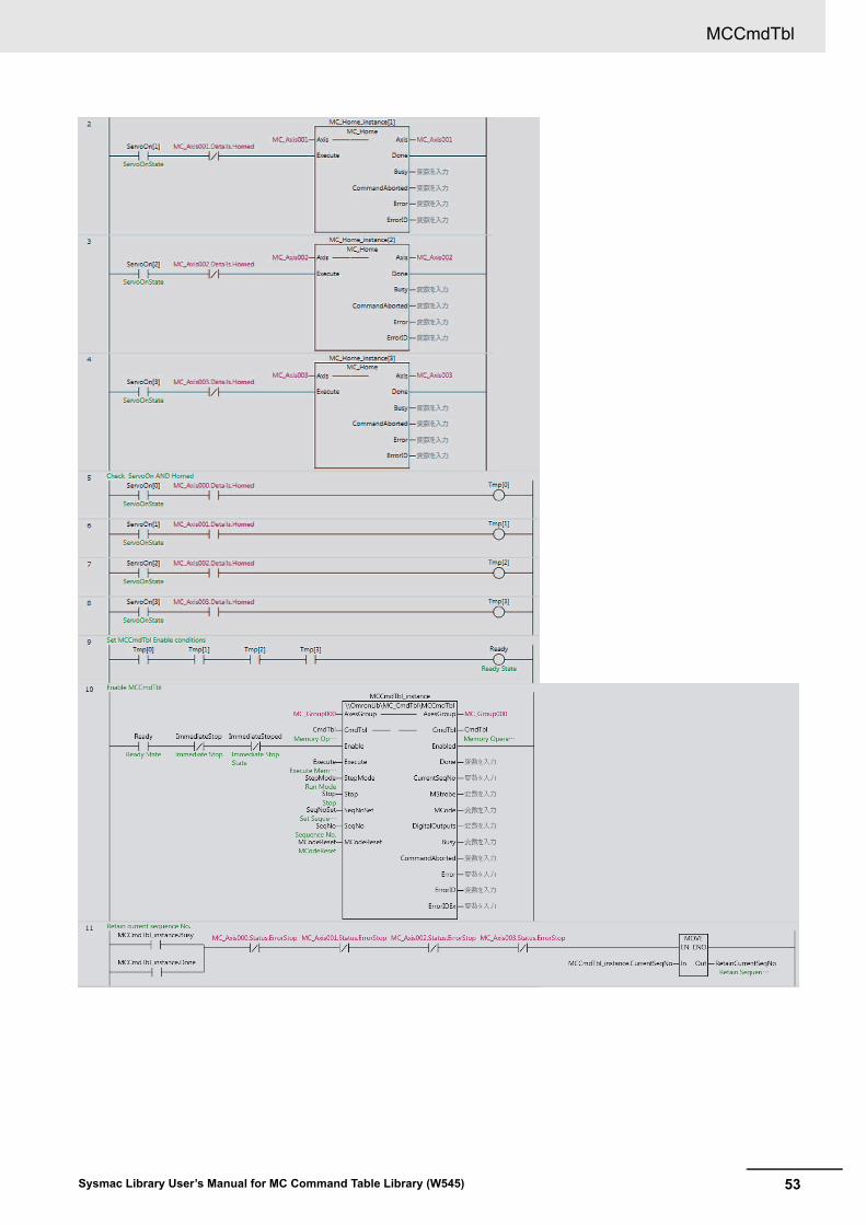
53
MCCmdTbl
Sysmac Library User’s Manual for MC Command Table Library (W545)
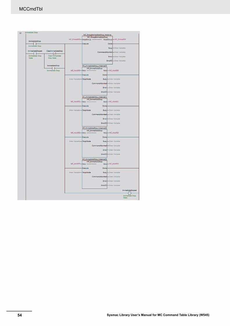
MCCmdTbl
54 Sysmac Library User’s Manual for MC Command Table Library (W545)
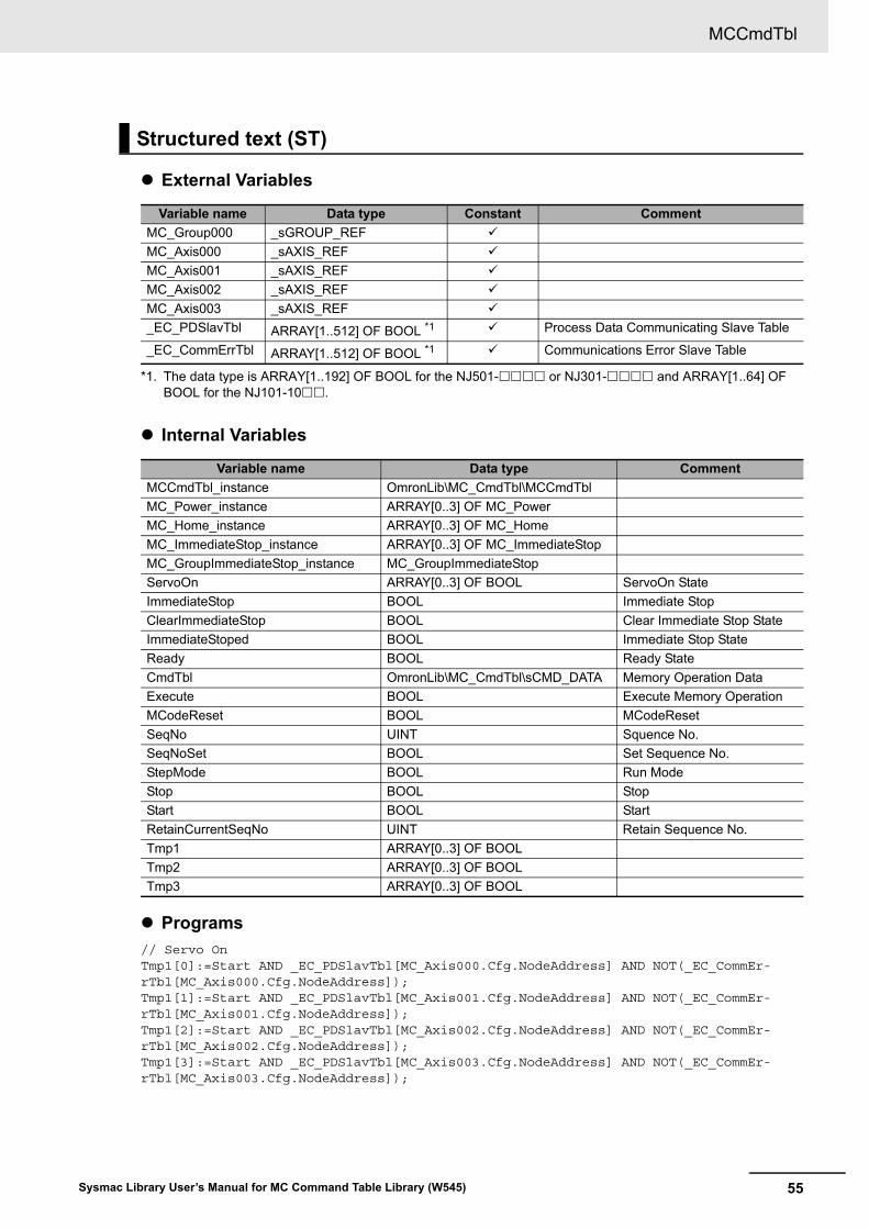
55
MCCmdTbl
Sysmac Library User’s Manual for MC Command Table Library (W545)
External Variables
Internal Variables
Programs
// Servo OnTmp1[0]:=Start AND _EC_PDSlavTbl[MC_Axis000.Cfg.NodeAddress] AND NOT(_EC_CommEr-rTbl[MC_Axis000.Cfg.NodeAddress]);Tmp1[1]:=Start AND _EC_PDSlavTbl[MC_Axis001.Cfg.NodeAddress] AND NOT(_EC_CommEr-rTbl[MC_Axis001.Cfg.NodeAddress]);Tmp1[2]:=Start AND _EC_PDSlavTbl[MC_Axis002.Cfg.NodeAddress] AND NOT(_EC_CommEr-rTbl[MC_Axis002.Cfg.NodeAddress]);Tmp1[3]:=Start AND _EC_PDSlavTbl[MC_Axis003.Cfg.NodeAddress] AND NOT(_EC_CommEr-rTbl[MC_Axis003.Cfg.NodeAddress]);
Structured text (ST)
Variable name Data type Constant Comment
MC_Group000 _sGROUP_REF
MC_Axis000 _sAXIS_REF
MC_Axis001 _sAXIS_REF
MC_Axis002 _sAXIS_REF
MC_Axis003 _sAXIS_REF
_EC_PDSlavTbl ARRAY[1..512] OF BOOL *1
*1. The data type is ARRAY[1..192] OF BOOL for the NJ501- or NJ301- and ARRAY[1..64] OF BOOL for the NJ101-10.
Process Data Communicating Slave Table
_EC_CommErrTbl ARRAY[1..512] OF BOOL *1 Communications Error Slave Table
Variable name Data type Comment
MCCmdTbl_instance OmronLib\MC_CmdTbl\MCCmdTbl
MC_Power_instance ARRAY[0..3] OF MC_Power
MC_Home_instance ARRAY[0..3] OF MC_Home
MC_ImmediateStop_instance ARRAY[0..3] OF MC_ImmediateStop
MC_GroupImmediateStop_instance MC_GroupImmediateStop
ServoOn ARRAY[0..3] OF BOOL ServoOn State
ImmediateStop BOOL Immediate Stop
ClearImmediateStop BOOL Clear Immediate Stop State
ImmediateStoped BOOL Immediate Stop State
Ready BOOL Ready State
CmdTbl OmronLib\MC_CmdTbl\sCMD_DATA Memory Operation Data
Execute BOOL Execute Memory Operation
MCodeReset BOOL MCodeReset
SeqNo UINT Squence No.
SeqNoSet BOOL Set Sequence No.
StepMode BOOL Run Mode
Stop BOOL Stop
Start BOOL Start
RetainCurrentSeqNo UINT Retain Sequence No.
Tmp1 ARRAY[0..3] OF BOOL
Tmp2 ARRAY[0..3] OF BOOL
Tmp3 ARRAY[0..3] OF BOOL
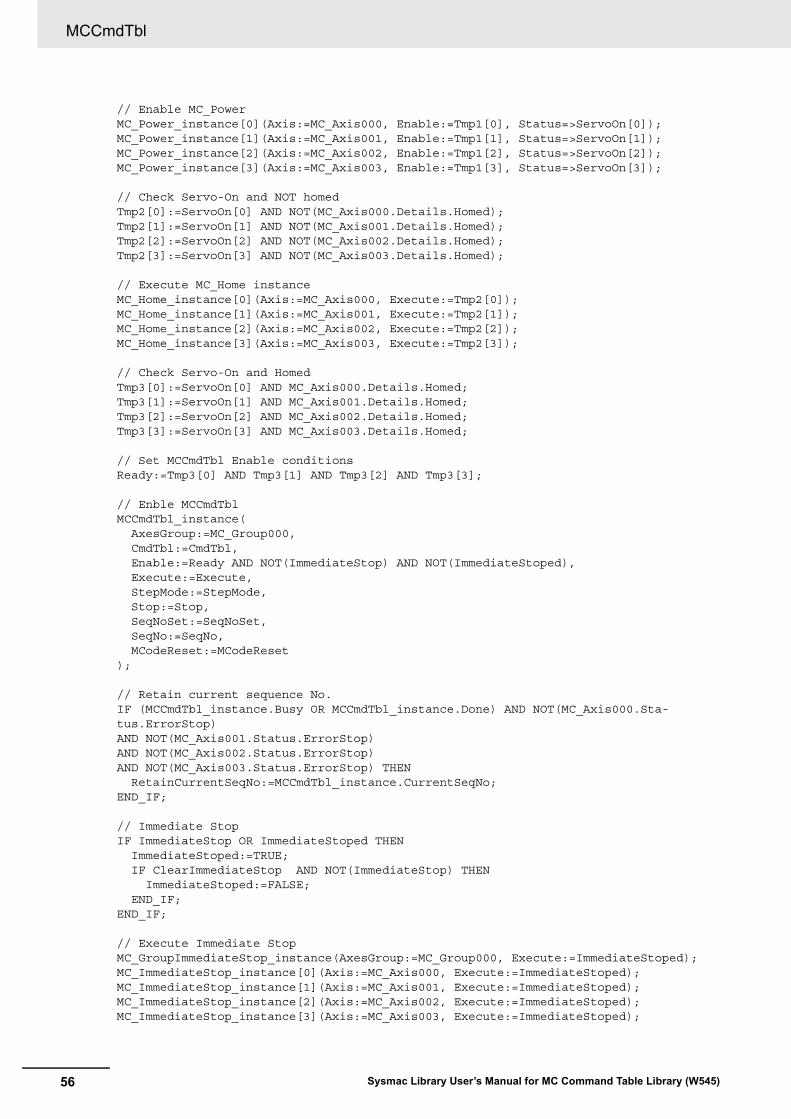
MCCmdTbl
56 Sysmac Library User’s Manual for MC Command Table Library (W545)
// Enable MC_PowerMC_Power_instance[0](Axis:=MC_Axis000, Enable:=Tmp1[0], Status=>ServoOn[0]);MC_Power_instance[1](Axis:=MC_Axis001, Enable:=Tmp1[1], Status=>ServoOn[1]);MC_Power_instance[2](Axis:=MC_Axis002, Enable:=Tmp1[2], Status=>ServoOn[2]);MC_Power_instance[3](Axis:=MC_Axis003, Enable:=Tmp1[3], Status=>ServoOn[3]);
// Check Servo-On and NOT homedTmp2[0]:=ServoOn[0] AND NOT(MC_Axis000.Details.Homed);Tmp2[1]:=ServoOn[1] AND NOT(MC_Axis001.Details.Homed);Tmp2[2]:=ServoOn[2] AND NOT(MC_Axis002.Details.Homed);Tmp2[3]:=ServoOn[3] AND NOT(MC_Axis003.Details.Homed);
// Execute MC_Home instanceMC_Home_instance[0](Axis:=MC_Axis000, Execute:=Tmp2[0]);MC_Home_instance[1](Axis:=MC_Axis001, Execute:=Tmp2[1]);MC_Home_instance[2](Axis:=MC_Axis002, Execute:=Tmp2[2]);MC_Home_instance[3](Axis:=MC_Axis003, Execute:=Tmp2[3]);
// Check Servo-On and HomedTmp3[0]:=ServoOn[0] AND MC_Axis000.Details.Homed;Tmp3[1]:=ServoOn[1] AND MC_Axis001.Details.Homed;Tmp3[2]:=ServoOn[2] AND MC_Axis002.Details.Homed;Tmp3[3]:=ServoOn[3] AND MC_Axis003.Details.Homed;
// Set MCCmdTbl Enable conditionsReady:=Tmp3[0] AND Tmp3[1] AND Tmp3[2] AND Tmp3[3];
// Enble MCCmdTblMCCmdTbl_instance( AxesGroup:=MC_Group000, CmdTbl:=CmdTbl, Enable:=Ready AND NOT(ImmediateStop) AND NOT(ImmediateStoped), Execute:=Execute, StepMode:=StepMode, Stop:=Stop, SeqNoSet:=SeqNoSet, SeqNo:=SeqNo, MCodeReset:=MCodeReset);
// Retain current sequence No.IF (MCCmdTbl_instance.Busy OR MCCmdTbl_instance.Done) AND NOT(MC_Axis000.Sta-tus.ErrorStop) AND NOT(MC_Axis001.Status.ErrorStop) AND NOT(MC_Axis002.Status.ErrorStop) AND NOT(MC_Axis003.Status.ErrorStop) THEN RetainCurrentSeqNo:=MCCmdTbl_instance.CurrentSeqNo;END_IF;
// Immediate StopIF ImmediateStop OR ImmediateStoped THEN ImmediateStoped:=TRUE; IF ClearImmediateStop AND NOT(ImmediateStop) THEN ImmediateStoped:=FALSE; END_IF;END_IF;
// Execute Immediate Stop MC_GroupImmediateStop_instance(AxesGroup:=MC_Group000, Execute:=ImmediateStoped);MC_ImmediateStop_instance[0](Axis:=MC_Axis000, Execute:=ImmediateStoped);MC_ImmediateStop_instance[1](Axis:=MC_Axis001, Execute:=ImmediateStoped);MC_ImmediateStop_instance[2](Axis:=MC_Axis002, Execute:=ImmediateStoped);MC_ImmediateStop_instance[3](Axis:=MC_Axis003, Execute:=ImmediateStoped);
57
MCCmdTbl
Sysmac Library User’s Manual for MC Command Table Library (W545)
Through an external circuit such as the above, the currently executing sequence number is retained in the RetainCurrentSeqNo internal variable.
Even if it is stopped with Stop, the value of this internal variable is not cleared.
External Circuits To Retain Executing Sequence Number

MCCmdTbl
58 Sysmac Library User’s Manual for MC Command Table Library (W545)

59Sysmac Library User’s Manual for MC Command Table Library (W545)
Appendix
Referring to Library Information
60 Sysmac Library User’s Manual for MC Command Table Library (W545)
Referring to Library Information
When you make an inquiry to OMRON about the library, you can refer to the library information to iden-tify the library to ask about.
The library information is useful in identifying the target library among the libraries provided by OMRON or created by the user.
The library information consists of the attributes of the library and the attributes of function blocks and functions contained in the library.
• Attributes of libraries
Information for identifying the library itself
• Attributes of function blocks and functions
Information for identifying the function block and function contained in the library
Use the Sysmac Studio to access the library information.
The following attributes of libraries, function blocks and functions are provided as the library informa-tion.
Attributes of Libraries
Attributes of Function Blocks and Functions
Attributes of Libraries, Function Blocks and Functions
No.*1
*1. These numbers correspond to the numbers shown on the screen images in the next section, Referring to Attributes of Libraries, Function Blocks and Functions on page 61.
Attribute Description
(1) Library file name The name of the library file
(2) Library version The version of the library
(3) Author The name of creator of the library
(4) Comment The description of the library*2
*2. It is provided in English and Japanese.
No.*1
*1. These numbers correspond to the numbers shown on the screen images in the next section, Referring to Attributes of Libraries, Function Blocks and Functions on page 61.
Attribute Description
(5) FB/FUN name The name of the function block or function
(6) Name space The name of name space for the function block or function
(7) FB/FUN version The version of the function block or function
(8) Author The name of creator of the function block or function
(9) FB/FUN number The function block number or function number
(10) Comment The description of the function block or function*2
*2. It is provided in English and Japanese.
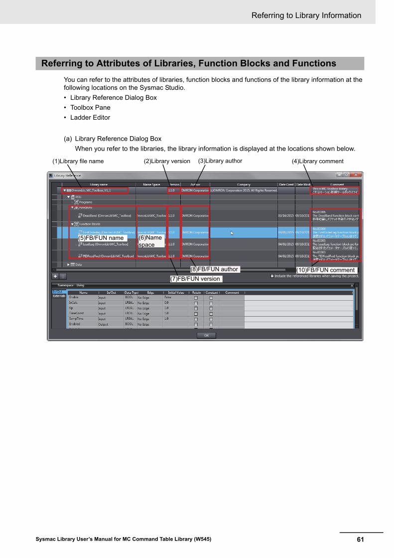
61
Referring to Library Information
Sysmac Library User’s Manual for MC Command Table Library (W545)
You can refer to the attributes of libraries, function blocks and functions of the library information at the following locations on the Sysmac Studio.
• Library Reference Dialog Box
• Toolbox Pane
• Ladder Editor
(a) Library Reference Dialog Box
When you refer to the libraries, the library information is displayed at the locations shown below.
Referring to Attributes of Libraries, Function Blocks and Functions
(2)Library version(1)Library file name (3)Library author (4)Library comment
(5)FB/FUN name
(7)FB/FUN version(8)FB/FUN author (10)FB/FUN comment
(6)Name space
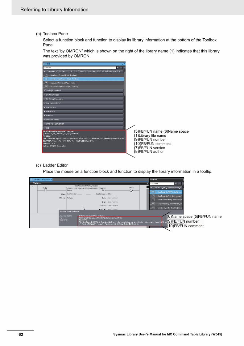
Referring to Library Information
62 Sysmac Library User’s Manual for MC Command Table Library (W545)
(b) Toolbox Pane
Select a function block and function to display its library information at the bottom of the Toolbox Pane.
The text “by OMRON” which is shown on the right of the library name (1) indicates that this library was provided by OMRON.
(c) Ladder Editor
Place the mouse on a function block and function to display the library information in a tooltip.
(5)FB/FUN name (6)Name space(1)Library file name(9)FB/FUN number(10)FB/FUN comment(7)FB/FUN version(8)FB/FUN author
(6)Name space (5)FB/FUN name
(10)FB/FUN comment(9)FB/FUN number

63
Referring to Function Block and Function Source Codes
Sysmac Library User’s Manual for MC Command Table Library (W545)
Referring to Function Block and Function Source Codes
You can refer to the source codes of function blocks and functions provided by OMRON to customize them to suit the user’s environment.
User function blocks and user functions can be created based on the copies of these source codes.
The following are the examples of items that you may need to customize.
• Customizing the size of arrays to suit the memory capacity of the user’s Controller
• Customizing the data types to suit the user-defined data types
Note that you can access only function blocks and functions whose Source code published/not pub-lished is set to Published in the library information shown in their individual specifications.
Use the following procedure to refer to the source codes of function blocks and functions.
1 Select a function block or function in the program.
2 Double-click or right-click and select To Lower Layer from the menu.
The source code is displayed.
Precautions for Correct Use
For function blocks and functions whose source codes are not published, the following dialog box is displayed in the above step 2. Click the Cancel button.

Referring to Function Block and Function Source Codes
64 Sysmac Library User’s Manual for MC Command Table Library (W545)


Authorized Distributor:
In the interest of product improvement, specifications are subject to change without notice.
Cat. No. W545-E1-04 1116
© OMRON Corporation 2015-2016 All Rights Reserved.
OMRON Corporation Industrial Automation Company
OMRON ELECTRONICS LLC2895 Greenspoint Parkway, Suite 200 Hoffman Estates, IL 60169 U.S.A.Tel: (1) 847-843-7900/Fax: (1) 847-843-7787
Regional HeadquartersOMRON EUROPE B.V.Wegalaan 67-69, 2132 JD HoofddorpThe NetherlandsTel: (31)2356-81-300/Fax: (31)2356-81-388
Contact: www.ia.omron.comKyoto, JAPAN
OMRON ASIA PACIFIC PTE. LTD.No. 438A Alexandra Road # 05-05/08 (Lobby 2), Alexandra Technopark, Singapore 119967Tel: (65) 6835-3011/Fax: (65) 6835-2711
OMRON (CHINA) CO., LTD.Room 2211, Bank of China Tower, 200 Yin Cheng Zhong Road, PuDong New Area, Shanghai, 200120, ChinaTel: (86) 21-5037-2222/Fax: (86) 21-5037-2200