sysmac library user’s manual for mc test run library filethe mc test run library is used to...
TRANSCRIPT
Sysmac Library
User’s Manual for MC Test Run Library
W546-E1-04
SYSMAC-XR001
All rights reserved. No part of this publication may be reproduced, stored in a retrieval system, or transmitted, in any form, or by any means, mechanical, electronic, photocopying, recording, or otherwise, without the prior written permission of OMRON.
No patent liability is assumed with respect to the use of the information contained herein. Moreover, because OMRON is constantly striving to improve its high-quality products, the information contained in this manual is subject to change without notice. Every precaution has been taken in the preparation of this manual. Neverthe-less, OMRON assumes no responsibility for errors or omissions. Neither is any liability assumed for damages resulting from the use of the information contained in this publication.
• Sysmac and SYSMAC are trademarks or registered trademarks of OMRON Corporation in Japan and other countries for OMRON factory automation products.
• Microsoft, Windows, Windows Vista, Excel, and Visual Basic are either registered trademarks or trademarks of Microsoft Corporation in the United States and other countries.
• EtherCAT® is registered trademark and patented technology, licensed by Beckhoff Automation GmbH, Germany.
• ODVA, CIP, CompoNet, DeviceNet, and EtherNet/IP are trademarks of ODVA.
• The SD and SDHC logos are trademarks of SD-3C, LLC.
Other company names and product names in this document are the trademarks or registered trademarks of their respective companies.
Trademarks
Copyrights
NOTE
Microsoft product screen shots reprinted with permission from Microsoft Corporation.
1
Introduction
Sysmac Library User’s Manual for MC Test Run Library (W546)
Introduction
Thank you for purchasing an NJ/NX-series CPU Unit or an NY-series Industrial PC.
This manual provides information required to use the function blocks in the MC Test Run Library. (“Function block” is sometimes abbreviated as “FB.”) Please read this manual and make sure you understand the functionality and performance of the NJ/NX-series CPU Unit before you attempt to use it in a control system.
This manual provides function block specifications. It does not describe application restrictions or com-bination restrictions for Controllers, Units, and components.
Refer to the user's manuals for all of the products in the application before you use any of the products.
Keep this manual in a safe place where it will be available for reference during operation.
The MC Test Run Library is used to perform a test run that the MC Function Module is used.
In this library, a processing to operate axes that an MPG (i.e. a manual pulse generator) was used is provided.
You can use this library to reduce manpower of programming when creating a test run program that an MPG was used.
You can use this library together with motion control instructions of the NJ/NX/NY-series Controller. Refer to the motion control instructions reference manual for details on motion control instructions of the NJ/NX/NY-series Controller.
This manual is intended for the following personnel, who must also have knowledge of electrical sys-tems(an electrical engineer or the equivalent).
• Personnel in charge of introducing FA systems.
• Personnel in charge of designing FA systems.
• Personnel in charge of installing and maintaining FA systems.
• Personnel in charge of managing FA systems and facilities.
For programming, this manual is intended for personnel who understand the programming language specifications in international standard IEC 61131-3 or Japanese standard JIS B 3503.
Features of the Library
Intended Audience
Introduction
2 Sysmac Library User’s Manual for MC Test Run Library (W546)
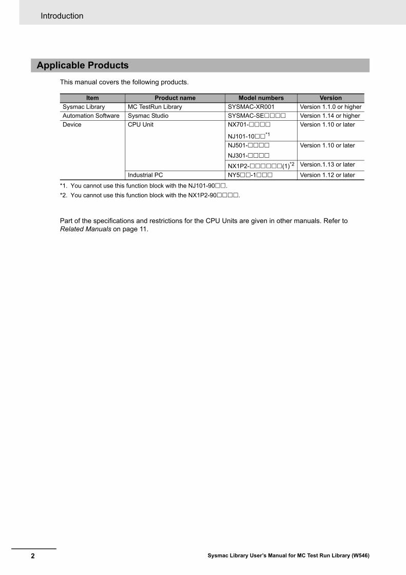
This manual covers the following products.
Part of the specifications and restrictions for the CPU Units are given in other manuals. Refer to Related Manuals on page 11.
Applicable Products
Item Product name Model numbers Version
Sysmac Library MC TestRun Library SYSMAC-XR001 Version 1.1.0 or higher
Automation Software Sysmac Studio SYSMAC-SE Version 1.14 or higher
Device CPU Unit NX701-
NJ101-10*1
*1. You cannot use this function block with the NJ101-90.
Version 1.10 or later
NJ501-
NJ301-
Version 1.10 or later
NX1P2-(1)*2
*2. You cannot use this function block with the NX1P2-90.
Version.1.13 or later
Industrial PC NY5-1 Version 1.12 or later

3
Manual Structure
Sysmac Library User’s Manual for MC Test Run Library (W546)
Manual Structure
Special information in this manual is classified as follows:
Precautions for Safe Use
Precautions on what to do and what not to do to ensure safe usage of the product.
Precautions for Correct Use
Precautions on what to do and what not to do to ensure proper operation and performance.
Additional Information
Additional information to read as required.This information is provided to increase understanding or make operation easier.
Version Information
Information on differences in specifications and functionality for CPU Units and Industrial PCs with different unit versions and for different versions of the Sysmac Studio are given.
Note References are provided to more detailed or related information.
Special Information
CONTENTS
4 Sysmac Library User’s Manual for MC Test Run Library (W546)
CONTENTS
Introduction ..............................................................................................................1Features of the Library................................................................................................................................. 1Intended Audience....................................................................................................................................... 1Applicable Products ..................................................................................................................................... 2
Manual Structure ......................................................................................................3Special Information ...................................................................................................................................... 3
CONTENTS................................................................................................................4
Terms and Conditions Agreement ..........................................................................6Warranty, Limitations of Liability .................................................................................................................. 6Application Considerations .......................................................................................................................... 7Disclaimers .................................................................................................................................................. 7
Safety Precautions ...................................................................................................8Definition of Precautionary Information........................................................................................................ 8Symbols ....................................................................................................................................................... 8Cautions....................................................................................................................................................... 9
Precautions for Correct Use..................................................................................10
Related Manuals ..................................................................................................... 11
Revision History .....................................................................................................13
Procedure to Use Sysmac Libraries.....................................................................15Procedure to Use Sysmac Libraries Installed Using the Installer .............................................................. 16Procedure to Use Sysmac Libraries Uploaded from a CPU Unit or an Industrial PC................................ 20
Common Specifications of Function Blocks .......................................................23Common Variables .................................................................................................................................... 24Precautions................................................................................................................................................ 30
Specifications of Individual Function Blocks ......................................................31MPGFilter................................................................................................................................................... 32
Appendix .................................................................................................................49Referring to Library Information ................................................................................................................. 50Referring to Function Block and Function Source Codes.......................................................................... 53

5
CONTENTS
Sysmac Library User’s Manual for MC Test Run Library (W546)
Terms and Conditions Agreement
6 Sysmac Library User’s Manual for MC Test Run Library (W546)
Terms and Conditions Agreement
Exclusive Warranty
Omron’s exclusive warranty is that the Products will be free from defects in materials and workman-ship for a period of twelve months from the date of sale by Omron (or such other period expressed in writing by Omron). Omron disclaims all other warranties, express or implied.
Limitations
OMRON MAKES NO WARRANTY OR REPRESENTATION, EXPRESS OR IMPLIED, ABOUT NON-INFRINGEMENT, MERCHANTABILITY OR FITNESS FOR A PARTICULAR PURPOSE OF THE PRODUCTS. BUYER ACKNOWLEDGES THAT IT ALONE HAS DETERMINED THAT THE PRODUCTS WILL SUITABLY MEET THE REQUIREMENTS OF THEIR INTENDED USE.
Omron further disclaims all warranties and responsibility of any type for claims or expenses based on infringement by the Products or otherwise of any intellectual property right.
Buyer Remedy
Omron’s sole obligation hereunder shall be, at Omron’s election, to (i) replace (in the form originally shipped with Buyer responsible for labor charges for removal or replacement thereof) the non-com-plying Product, (ii) repair the non-complying Product, or (iii) repay or credit Buyer an amount equal to the purchase price of the non-complying Product; provided that in no event shall Omron be responsible for warranty, repair, indemnity or any other claims or expenses regarding the Products unless Omron’s analysis confirms that the Products were properly handled, stored, installed and maintained and not subject to contamination, abuse, misuse or inappropriate modification. Return of any Products by Buyer must be approved in writing by Omron before shipment. Omron Companies shall not be liable for the suitability or unsuitability or the results from the use of Products in combi-nation with any electrical or electronic components, circuits, system assemblies or any other materi-als or substances or environments. Any advice, recommendations or information given orally or in writing, are not to be construed as an amendment or addition to the above warranty.
See http://www.omron.com/global/ or contact your Omron representative for published information.
OMRON COMPANIES SHALL NOT BE LIABLE FOR SPECIAL, INDIRECT, INCIDENTAL, OR CON-SEQUENTIAL DAMAGES, LOSS OF PROFITS OR PRODUCTION OR COMMERCIAL LOSS IN ANY WAY CONNECTED WITH THE PRODUCTS, WHETHER SUCH CLAIM IS BASED IN CONTRACT, WARRANTY, NEGLIGENCE OR STRICT LIABILITY.
Further, in no event shall liability of Omron Companies exceed the individual price of the Product on which liability is asserted.
Warranty, Limitations of Liability
Warranties
Limitation on Liability; Etc
7
Terms and Conditions Agreement
Sysmac Library User’s Manual for MC Test Run Library (W546)
Omron Companies shall not be responsible for conformity with any standards, codes or regulations which apply to the combination of the Product in the Buyer’s application or use of the Product. At Buyer’s request, Omron will provide applicable third party certification documents identifying ratings and limitations of use which apply to the Product. This information by itself is not sufficient for a com-plete determination of the suitability of the Product in combination with the end product, machine, sys-tem, or other application or use. Buyer shall be solely responsible for determining appropriateness of the particular Product with respect to Buyer’s application, product or system. Buyer shall take applica-tion responsibility in all cases.
NEVER USE THE PRODUCT FOR AN APPLICATION INVOLVING SERIOUS RISK TO LIFE OR PROPERTY WITHOUT ENSURING THAT THE SYSTEM AS A WHOLE HAS BEEN DESIGNED TO ADDRESS THE RISKS, AND THAT THE OMRON PRODUCT(S) IS PROPERLY RATED AND INSTALLED FOR THE INTENDED USE WITHIN THE OVERALL EQUIPMENT OR SYSTEM.
Omron Companies shall not be responsible for the user’s programming of a programmable Product, or any consequence thereof.
Data presented in Omron Company websites, catalogs and other materials is provided as a guide for the user in determining suitability and does not constitute a warranty. It may represent the result of Omron’s test conditions, and the user must correlate it to actual application requirements. Actual perfor-mance is subject to the Omron’s Warranty and Limitations of Liability.
Product specifications and accessories may be changed at any time based on improvements and other reasons. It is our practice to change part numbers when published ratings or features are changed, or when significant construction changes are made. However, some specifications of the Product may be changed without any notice. When in doubt, special part numbers may be assigned to fix or establish key specifications for your application. Please consult with your Omron’s representative at any time to confirm actual specifications of purchased Product.
Information presented by Omron Companies has been checked and is believed to be accurate; how-ever, no responsibility is assumed for clerical, typographical or proofreading errors or omissions.
Application Considerations
Suitability of Use
Programmable Products
Disclaimers
Performance Data
Change in Specifications
Errors and Omissions
Safety Precautions
8 Sysmac Library User’s Manual for MC Test Run Library (W546)
Safety Precautions
The following notation is used in this user’s manual to provide precautions required to ensure safe usage of an NJ/NX-series CPU Unit and an NY-series Industrial PC.
The safety precautions that are provided are extremely important to safety. Always read and heed the information provided in all safety precautions.
The following notation is used.
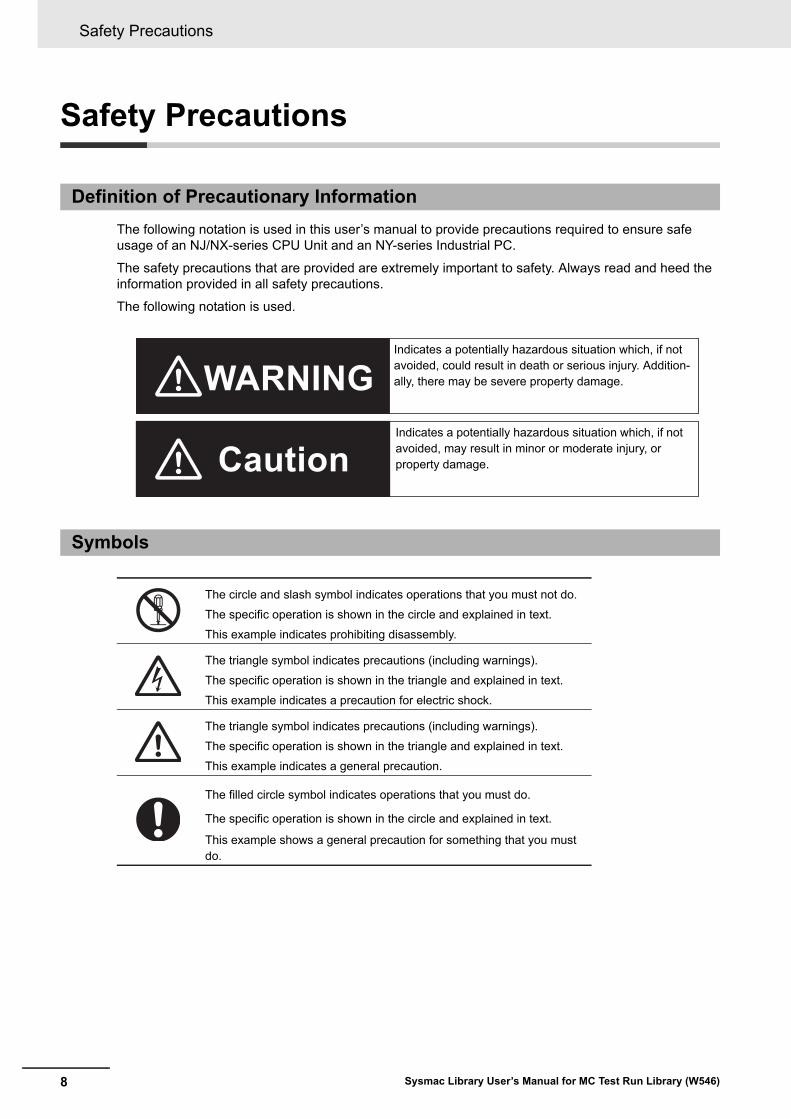
Definition of Precautionary Information
Symbols
The circle and slash symbol indicates operations that you must not do.
The specific operation is shown in the circle and explained in text.
This example indicates prohibiting disassembly.
The triangle symbol indicates precautions (including warnings).
The specific operation is shown in the triangle and explained in text.
This example indicates a precaution for electric shock.
The triangle symbol indicates precautions (including warnings).
The specific operation is shown in the triangle and explained in text.
This example indicates a general precaution.
The filled circle symbol indicates operations that you must do.
The specific operation is shown in the circle and explained in text.
This example shows a general precaution for something that you must do.
WARNING
Caution
Indicates a potentially hazardous situation which, if not avoided, could result in death or serious injury. Addition-ally, there may be severe property damage.
Indicates a potentially hazardous situation which, if not avoided, may result in minor or moderate injury, or property damage.

9
Safety Precautions
Sysmac Library User’s Manual for MC Test Run Library (W546)
Cautions
CautionRead all related manuals carefully before you use this library.
Emergency stop circuits, interlock circuits, limit circuits, and similar safety measures must be provided in external control circuits.
Check the user program, data, and parameter settings for proper execution before you use them for actual operation.
When you perform a test run, hold an emergency stop switch in your hand or other-wise prepare for rapid motor operation.
Precautions for Correct Use
10 Sysmac Library User’s Manual for MC Test Run Library (W546)
Precautions for Correct Use
• When you use the library, functions or function blocks that are not described in the library manual may be displayed on the Sysmac Studio. Do not use functions or function blocks that are not described in the manual.
• The sample programming shows only the portion of a program that uses the function or function block from the library.
• When using actual devices, also program safety circuits, device interlocks, I/O with other devices, and other control procedures.
• Create a user program that will produce the intended device operation.
• Check the user program for proper execution before you use it for actual operation.
• When you use a function block that changes an Enabled output variable to TRUE while the process-ing result is output normally, confirm that Enabled is TRUE before you use the processing result.
• If the Counter Mode is Rotary Mode for the master axis, this function block will always use the short-est way to judge positioning.
• If you use the processing result of this function block to output a command position to a motor, always specify the shortest way specification.
Using the Library
Using Sample Programming
Operation
11
Related Manuals
Sysmac Library User’s Manual for MC Test Run Library (W546)
Related Manuals
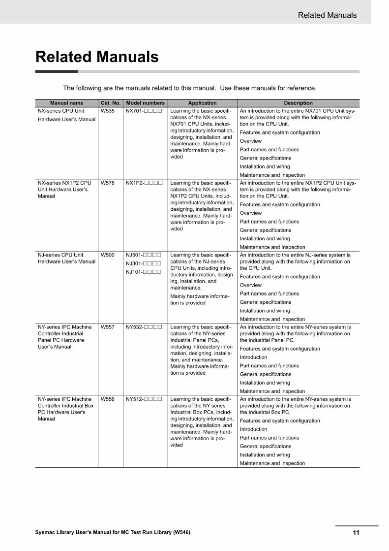
The following are the manuals related to this manual. Use these manuals for reference.
Manual name Cat. No. Model numbers Application Description
NX-series CPU Unit
Hardware User’s Manual
W535 NX701- Learning the basic specifi-cations of the NX-series NX701 CPU Units, includ-ing introductory information, designing, installation, and maintenance. Mainly hard-ware information is pro-vided
An introduction to the entire NX701 CPU Unit sys-tem is provided along with the following informa-tion on the CPU Unit.
Features and system configuration
Overview
Part names and functions
General specifications
Installation and wiring
Maintenance and inspection
NX-series NX1P2 CPU Unit Hardware User’s Manual
W578 NX1P2- Learning the basic specifi-cations of the NX-series NX1P2 CPU Units, includ-ing introductory information, designing, installation, and maintenance. Mainly hard-ware information is pro-vided
An introduction to the entire NX1P2 CPU Unit sys-tem is provided along with the following informa-tion on the CPU Unit.
Features and system configuration
Overview
Part names and functions
General specifications
Installation and wiring
Maintenance and Inspection
NJ-series CPU Unit Hardware User’s Manual
W500 NJ501-
NJ301-
NJ101-
Learning the basic specifi-cations of the NJ-series CPU Units, including intro-ductory information, design-ing, installation, and maintenance.
Mainly hardware informa-tion is provided
An introduction to the entire NJ-series system is provided along with the following information on the CPU Unit.
Features and system configuration
Overview
Part names and functions
General specifications
Installation and wiring
Maintenance and inspection
NY-series IPC Machine Controller Industrial Panel PC Hardware User’s Manual
W557 NY532- Learning the basic specifi-cations of the NY-series Industrial Panel PCs, including introductory infor-mation, designing, installa-tion, and maintenance. Mainly hardware informa-tion is provided
An introduction to the entire NY-series system is provided along with the following information on the Industrial Panel PC.
Features and system configuration
Introduction
Part names and functions
General specifications
Installation and wiring
Maintenance and inspection
NY-series IPC Machine Controller Industrial Box PC Hardware User's Manual
W556 NY512- Learning the basic specifi-cations of the NY-series Industrial Box PCs, includ-ing introductory information, designing, installation, and maintenance. Mainly hard-ware information is pro-vided
An introduction to the entire NY-series system is provided along with the following information on the Industrial Box PC.
Features and system configuration
Introduction
Part names and functions
General specifications
Installation and wiring
Maintenance and inspection

Related Manuals
12 Sysmac Library User’s Manual for MC Test Run Library (W546)
NJ/NX-series CPU Unit Software User’s Manual
W501 NX701-
NJ501-
NJ301-
NJ101-
NX1P2-
Learning how to program and set up an NJ/NX-series CPU Unit.
Mainly software informa-tion is provided
The following information is provided on a Control-ler built with an NJ/NX-series CPU Unit.
CPU Unit operation
CPU Unit features
Initial settings
Programming based on IEC 61131-3 language specifications
NY-series IPC Machine Controller Industrial Panel PC / Industrial Box PC Software User’s Manual
W558 NY532-
NY512-
Learning how to program and set up the Controller functions of an NY-series Industrial PC
The following information is provided on NY-series Machine Automation Control Software.
Controller operation
Controller features
Controller settings
Programming based on IEC 61131-3 language specifications
NJ/NX-series Instruc-tions Reference Manual
W502 NX701-
NJ501-
NJ301-
NJ101-
NX1P2-
Learning detailed specifica-tions on the basic instruc-tions of an NJ/NX-series CPU Unit
The instructions in the instruction set (IEC 61131-3 specifications) are described.
NY-series Instructions Reference Manual
W560 NY532-
NY512-
Learning detailed specifica-tions on the basic instruc-tions of an NY-series Industrial PC
The instructions in the instruction set (IEC 61131-3 specifications) are described.
NJ/NX-series CPU Unit Motion Control User's Manual
W507 NX701-NJ501-NJ301-NJ101-NX1P2-
Learning about motion con-trol settings and program-ming concepts of an NJ/NX-series CPU Unit.
The settings and operation of the CPU Unit and programming concepts for motion control are described.
NY-series IPC Machine Controller Industrial Panel PC / Industrial Box PC Motion Control User’s Manual
W559 NY532-
NY512-
Learning about motion con-trol settings and program-ming concepts of an NY-series Industrial PC.
The settings and operation of the Controller and programming concepts for motion control are described.
NJ/NX-series Motion Control Instructions Ref-erence Manual
W508 NX701-NJ501-NJ301-NJ101-NX1P2-
Learning about the specifi-cations of the motion con-trol instructions of an NJ/NX-series CPU Unit.
The motion control instructions are described.
NY-series Motion Control Instructions Reference Manual
W561 NY532-
NY512-
Learning about the specifi-cations of the motion con-trol instructions of an NY-series Industrial PC.
The motion control instructions are described.
Sysmac Studio Version 1 Operation Manual
W504 SYSMAC-SE2
Learning about the operat-ing procedures and func-tions of the Sysmac Studio.
Describes the operating procedures of the Sysmac Studio.
Manual name Cat. No. Model numbers Application Description

13
Revision History
Sysmac Library User’s Manual for MC Test Run Library (W546)
Revision History
A manual revision code appears as a suffix to the catalog number on the front and back covers of the manual.
Revision code Date Revised content
01 April 2015 Original production
02 December 2015 Corrected mistakes.
03 July 2016 Changed the manual name.
04 November 2016 Changed the manual name.
W546-E1-04Revision code
Cat. No.
Revision History
14 Sysmac Library User’s Manual for MC Test Run Library (W546)

15Sysmac Library User’s Manual for MC Test Run Library (W546)
Procedure to Use Sysmac Libraries
Procedure to Use Sysmac Libraries Installed Using the Installer
16 Sysmac Library User’s Manual for MC Test Run Library (W546)
Procedure to Use Sysmac Librar-ies Installed Using the Installer
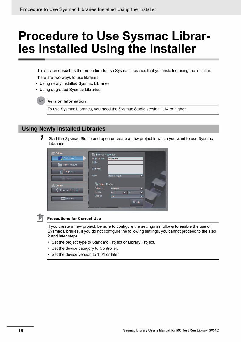
This section describes the procedure to use Sysmac Libraries that you installed using the installer.
There are two ways to use libraries.
• Using newly installed Sysmac Libraries
• Using upgraded Sysmac Libraries
Version Information
To use Sysmac Libraries, you need the Sysmac Studio version 1.14 or higher.
1 Start the Sysmac Studio and open or create a new project in which you want to use Sysmac Libraries.
Precautions for Correct Use
If you create a new project, be sure to configure the settings as follows to enable the use of Sysmac Libraries. If you do not configure the following settings, you cannot proceed to the step 2 and later steps.
• Set the project type to Standard Project or Library Project.
• Set the device category to Controller.
• Set the device version to 1.01 or later.
Using Newly Installed Libraries
17
Procedure to Use Sysmac Libraries Installed Using the Installer
Sysmac Library User’s Manual for MC Test Run Library (W546)
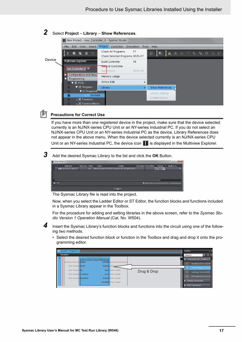
2 Select Project – Library – Show References.
Precautions for Correct Use
If you have more than one registered device in the project, make sure that the device selected currently is an NJ/NX-series CPU Unit or an NY-series Industrial PC. If you do not select an NJ/NX-series CPU Unit or an NY-series Industrial PC as the device, Library References does not appear in the above menu. When the device selected currently is an NJ/NX-series CPU
Unit or an NY-series Industrial PC, the device icon is displayed in the Multiview Explorer.
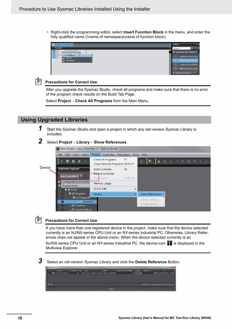
3 Add the desired Sysmac Library to the list and click the OK Button.
The Sysmac Library file is read into the project.
Now, when you select the Ladder Editor or ST Editor, the function blocks and functions included in a Sysmac Library appear in the Toolbox.
For the procedure for adding and setting libraries in the above screen, refer to the Sysmac Stu-dio Version 1 Operation Manual (Cat. No. W504).
4 Insert the Sysmac Library’s function blocks and functions into the circuit using one of the follow-ing two methods.
• Select the desired function block or function in the Toolbox and drag and drop it onto the pro-gramming editor.
Device
Drug & Drop
Procedure to Use Sysmac Libraries Installed Using the Installer
18 Sysmac Library User’s Manual for MC Test Run Library (W546)
• Right-click the programming editor, select Insert Function Block in the menu, and enter the fully qualified name (\\name of namespace\name of function block).
Precautions for Correct Use
After you upgrade the Sysmac Studio, check all programs and make sure that there is no error of the program check results on the Build Tab Page.
Select Project – Check All Programs from the Main Menu.
1 Start the Sysmac Studio and open a project in which any old-version Sysmac Library is included.
2 Select Project – Library – Show References.
Precautions for Correct Use
If you have more than one registered device in the project, make sure that the device selected currently is an NJ/NX-series CPU Unit or an NY-series Industrial PC. Otherwise, Library Refer-ences does not appear in the above menu. When the device selected currently is an
NJ/NX-series CPU Unit or an NY-series Industrial PC, the device icon is displayed in the Multiview Explorer.
3 Select an old-version Sysmac Library and click the Delete Reference Button.
Using Upgraded Libraries
Device
19
Procedure to Use Sysmac Libraries Installed Using the Installer
Sysmac Library User’s Manual for MC Test Run Library (W546)
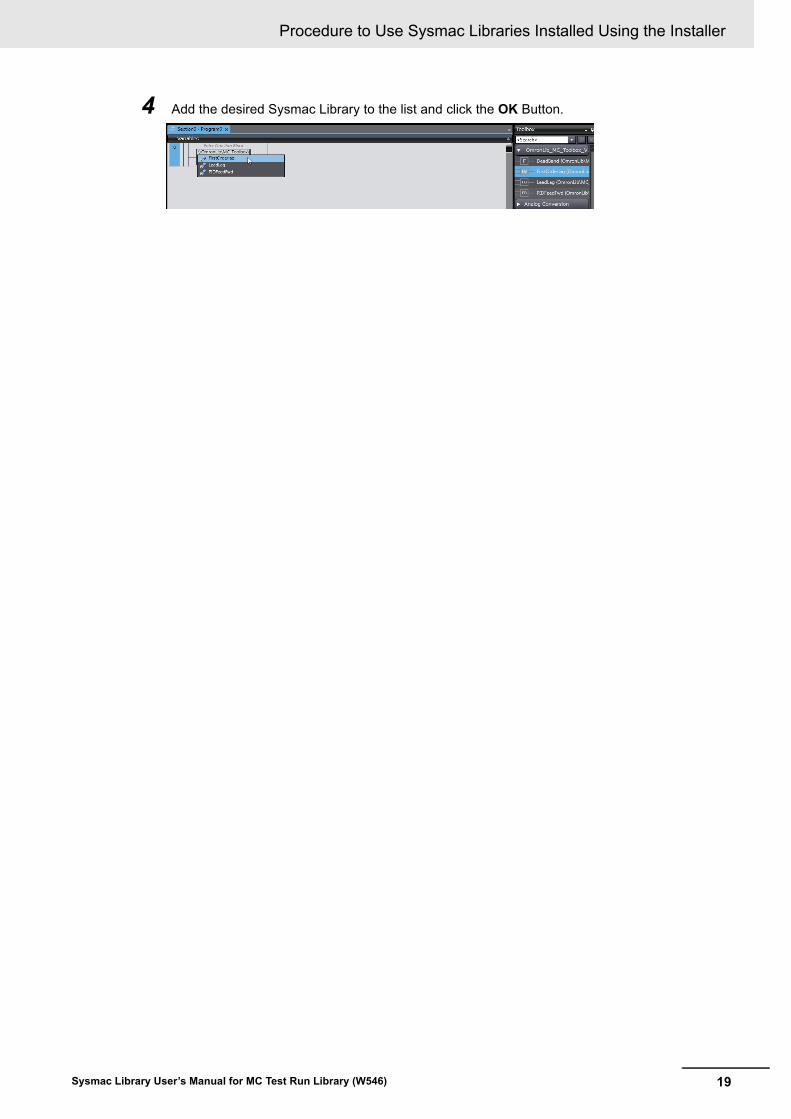
4 Add the desired Sysmac Library to the list and click the OK Button.
Procedure to Use Sysmac Libraries Uploaded from a CPU Unit or an Industrial PC
20 Sysmac Library User’s Manual for MC Test Run Library (W546)
Procedure to Use Sysmac Librar-ies Uploaded from a CPU Unit or an Industrial PC
You can use Sysmac Libraries uploaded from a CPU Unit or an Industrial PC to your computer if they are not installed.
The procedure to use uploaded Sysmac Libraries from a CPU Unit or an Industrial PC is as follows.
Version Information
To use Sysmac Libraries, you need the Sysmac Studio version 1.14 or higher.
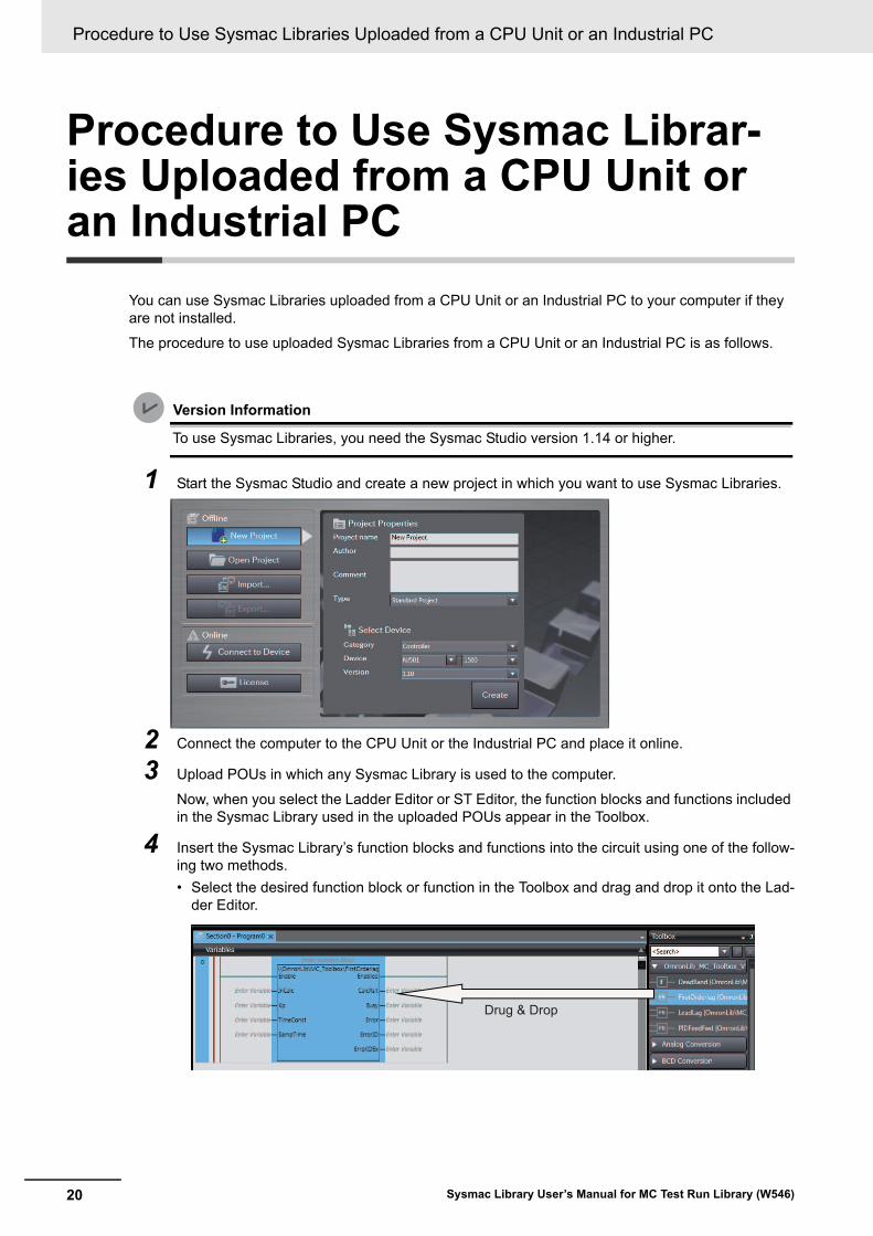
1 Start the Sysmac Studio and create a new project in which you want to use Sysmac Libraries.
2 Connect the computer to the CPU Unit or the Industrial PC and place it online.
3 Upload POUs in which any Sysmac Library is used to the computer.
Now, when you select the Ladder Editor or ST Editor, the function blocks and functions included in the Sysmac Library used in the uploaded POUs appear in the Toolbox.
4 Insert the Sysmac Library’s function blocks and functions into the circuit using one of the follow-ing two methods.
• Select the desired function block or function in the Toolbox and drag and drop it onto the Lad-der Editor.
Drug & Drop

21
Procedure to Use Sysmac Libraries Uploaded from a CPU Unit or an Industrial PC
Sysmac Library User’s Manual for MC Test Run Library (W546)
• Right-click the programming editor, select Insert Function Block in the menu, and enter the fully qualified name (\\name of namespace\name of function block).
Precautions for Correct Use
• The Sysmac Studio installs library files of the uploaded Sysmac Stutio to the specified folder on the computer if they are not present. However, the Sysmac Studio does not install library files to the specified folder on the computer if they are present.
The specified folder here means the folder in which library files are installed by the installer.
• Note that uploading Sysmac Libraries from a CPU Unit or an Industrial PC does not install the manual and help files for the Sysmac Libraries, unlike the case where you install then using the installer. Please install the manual and help files using the installer if you need them.
Procedure to Use Sysmac Libraries Uploaded from a CPU Unit or an Industrial PC
22 Sysmac Library User’s Manual for MC Test Run Library (W546)
23Sysmac Library User’s Manual for MC Test Run Library (W546)
Common Specifications of Function Blocks
Common Variables
24 Sysmac Library User’s Manual for MC Test Run Library (W546)
Common Variables
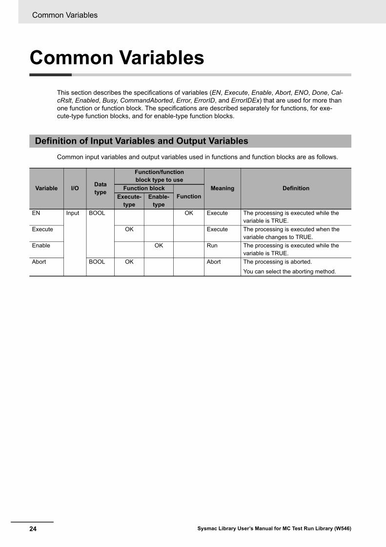
This section describes the specifications of variables (EN, Execute, Enable, Abort, ENO, Done, Cal-cRslt, Enabled, Busy, CommandAborted, Error, ErrorID, and ErrorIDEx) that are used for more than one function or function block. The specifications are described separately for functions, for exe-cute-type function blocks, and for enable-type function blocks.
Common input variables and output variables used in functions and function blocks are as follows.
Definition of Input Variables and Output Variables
Variable I/OData type
Function/function block type to use
Meaning DefinitionFunction blockFunctionExecute-
typeEnable-
type
EN Input BOOL OK Execute The processing is executed while the variable is TRUE.
Execute OK Execute The processing is executed when the variable changes to TRUE.
Enable OK Run The processing is executed while the variable is TRUE.
Abort BOOL OK Abort The processing is aborted.
You can select the aborting method.
25
Common Variables
Sysmac Library User’s Manual for MC Test Run Library (W546)
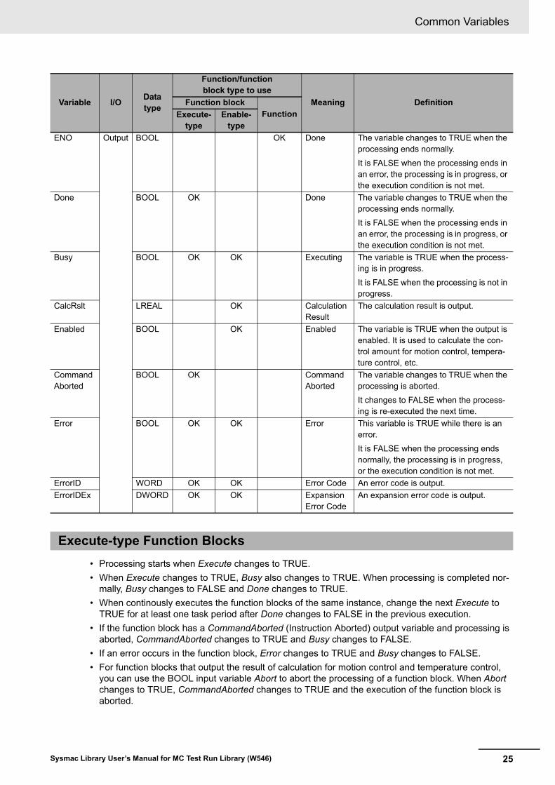
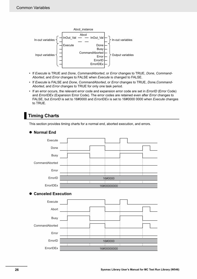
• Processing starts when Execute changes to TRUE.
• When Execute changes to TRUE, Busy also changes to TRUE. When processing is completed nor-mally, Busy changes to FALSE and Done changes to TRUE.
• When continously executes the function blocks of the same instance, change the next Execute to TRUE for at least one task period after Done changes to FALSE in the previous execution.
• If the function block has a CommandAborted (Instruction Aborted) output variable and processing is aborted, CommandAborted changes to TRUE and Busy changes to FALSE.
• If an error occurs in the function block, Error changes to TRUE and Busy changes to FALSE.
• For function blocks that output the result of calculation for motion control and temperature control, you can use the BOOL input variable Abort to abort the processing of a function block. When Abort changes to TRUE, CommandAborted changes to TRUE and the execution of the function block is aborted.
ENO Output BOOL OK Done The variable changes to TRUE when the processing ends normally.
It is FALSE when the processing ends in an error, the processing is in progress, or the execution condition is not met.
Done BOOL OK Done The variable changes to TRUE when the processing ends normally.
It is FALSE when the processing ends in an error, the processing is in progress, or the execution condition is not met.
Busy BOOL OK OK Executing The variable is TRUE when the process-ing is in progress.
It is FALSE when the processing is not in progress.
CalcRslt LREAL OK Calculation Result
The calculation result is output.
Enabled BOOL OK Enabled The variable is TRUE when the output is enabled. It is used to calculate the con-trol amount for motion control, tempera-ture control, etc.
Command Aborted
BOOL OK Command Aborted
The variable changes to TRUE when the processing is aborted.
It changes to FALSE when the process-ing is re-executed the next time.
Error BOOL OK OK Error This variable is TRUE while there is an error.
It is FALSE when the processing ends normally, the processing is in progress, or the execution condition is not met.
ErrorID WORD OK OK Error Code An error code is output.
ErrorIDEx DWORD OK OK Expansion Error Code
An expansion error code is output.
Execute-type Function Blocks
Variable I/OData type
Function/function block type to use
Meaning DefinitionFunction blockFunctionExecute-
typeEnable-
type
Common Variables
26 Sysmac Library User’s Manual for MC Test Run Library (W546)
• If Execute is TRUE and Done, CommandAborted, or Error changes to TRUE, Done, Command-Aborted, and Error changes to FALSE when Execute is changed to FALSE.
• If Execute is FALSE and Done, CommandAborted, or Error changes to TRUE, Done,Command-Aborted, and Error changes to TRUE for only one task period.
• If an error occurs, the relevant error code and expansion error code are set in ErrorID (Error Code) and ErrorIDEx (Expansion Error Code). The error codes are retained even after Error changes to FALSE, but ErrorID is set to 16#0000 and ErrorIDEx is set to 16#0000 0000 when Execute changes to TRUE.
This section provides timing charts for a normal end, aborted execution, and errors.
Normal End
Canceled Execution
Timing Charts
In-out variables
Input variables
In-out variables
Output variables
Abcd_instance
InOut_Val InOut_Val
ErrorErrorID
ErrorIDEx
CommandAborted
Abcd
Execute DoneBusy
Busy
Done
CommandAborted
Error
16#00000000
16#0000ErrorID
ErrorIDEx
Execute
Busy
Abort
CommandAborted
Error
16#00000000
16#0000ErrorID
ErrorIDEx
Execute

27
Common Variables
Sysmac Library User’s Manual for MC Test Run Library (W546)
Aborted Execution
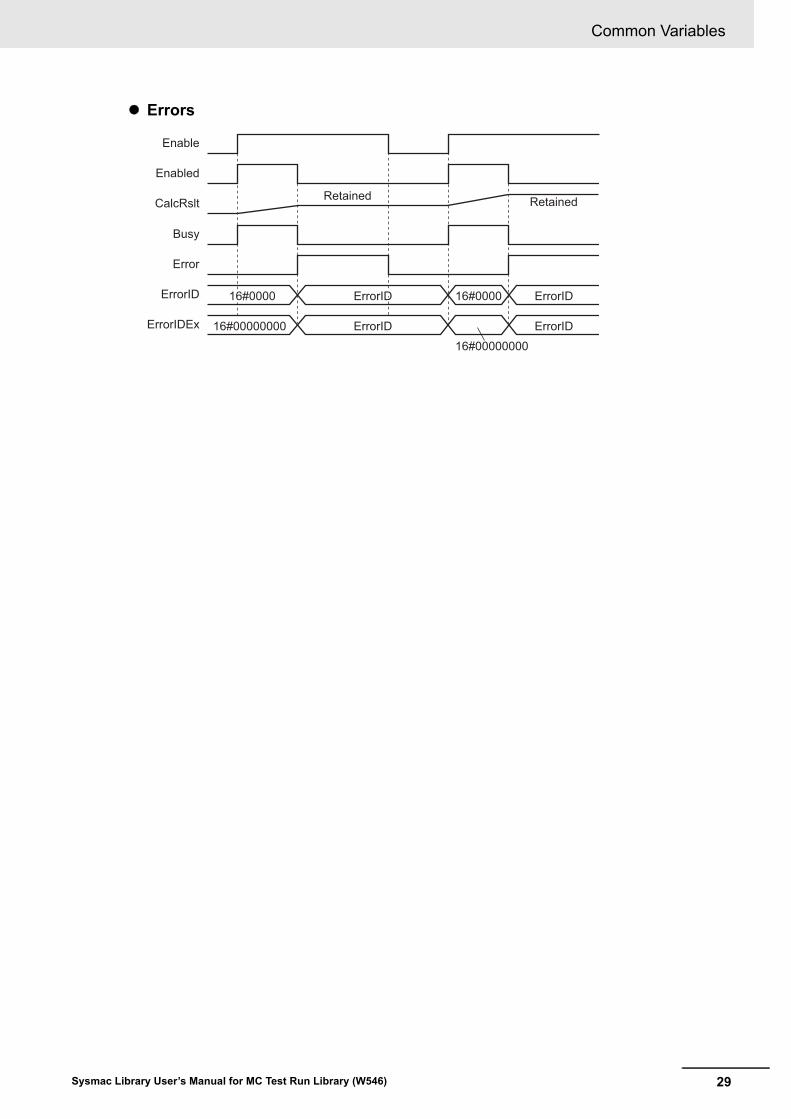
Errors
Busy
Done
CommandAborted
Error
16#00000000
16#0000ErrorID
ErrorIDEx
Execute
Busy
Done
CommandAborted
Error
16#0000 16#0000ErrorID
16#00000000 16#00000000ErrorIDEx ErrorIDExErrorIDEx
Execute
ErrorIDErrorIDErrorID ErrorID
Common Variables
28 Sysmac Library User’s Manual for MC Test Run Library (W546)
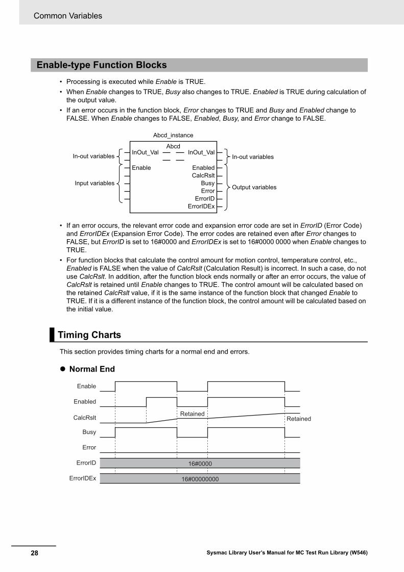
• Processing is executed while Enable is TRUE.
• When Enable changes to TRUE, Busy also changes to TRUE. Enabled is TRUE during calculation of the output value.
• If an error occurs in the function block, Error changes to TRUE and Busy and Enabled change to FALSE. When Enable changes to FALSE, Enabled, Busy, and Error change to FALSE.
• If an error occurs, the relevant error code and expansion error code are set in ErrorID (Error Code) and ErrorIDEx (Expansion Error Code). The error codes are retained even after Error changes to FALSE, but ErrorID is set to 16#0000 and ErrorIDEx is set to 16#0000 0000 when Enable changes to TRUE.
• For function blocks that calculate the control amount for motion control, temperature control, etc., Enabled is FALSE when the value of CalcRslt (Calculation Result) is incorrect. In such a case, do not use CalcRslt. In addition, after the function block ends normally or after an error occurs, the value of CalcRslt is retained until Enable changes to TRUE. The control amount will be calculated based on the retained CalcRslt value, if it is the same instance of the function block that changed Enable to TRUE. If it is a different instance of the function block, the control amount will be calculated based on the initial value.
This section provides timing charts for a normal end and errors.
Normal End
Enable-type Function Blocks
Timing Charts
In-out variables
Input variables
In-out variables
Output variables
Abcd_instance
InOut_Val InOut_Val
BusyError
ErrorID
Abcd
Enable EnabledCalcRslt
ErrorIDEx
Busy
Enabled
Error
16#00000000
16#0000ErrorID
ErrorIDEx
Enable
CalcRslt RetainedRetained
29
Common Variables
Sysmac Library User’s Manual for MC Test Run Library (W546)
Errors
Busy
Enabled
Error
16#000016#0000 16#0000ErrorID
ErrorIDEx
Enable
ErrorIDErrorIDErrorID ErrorID
16#00000000
16#00000000
ErrorIDErrorIDErrorID ErrorID
16#0000
CalcRslt Retained Retained
Precautions
30 Sysmac Library User’s Manual for MC Test Run Library (W546)
Precautions
This section provides precautions for the use of this function block.
You can nest calls to this function block for up to four levels.
For details on nesting, refer to the software user’s manual.
You cannot use the upward differentiation option for this function block.
Execute-type function blocks cannot be re-executed by the same instance.
If you do so, the output value will be the initial value.
For details on re-execution, refer to the motion control user’s manual.
Nesting
Instruction Options
Re-execution of Function Blocks
31Sysmac Library User’s Manual for MC Test Run Library (W546)
Specifications of Individual Function Blocks
Function block name Name Page
MPGFilter MPG Filter P. 32
MPGFilter
32 Sysmac Library User’s Manual for MC Test Run Library (W546)
MPGFilter
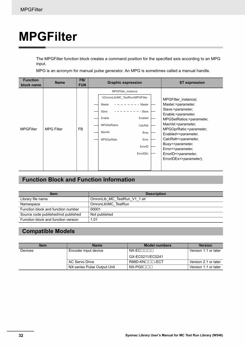
The MPGFilter function block creates a command position for the specified axis according to an MPG input.
MPG is an acronym for manual pulse generator. An MPG is sometimes called a manual handle.
Function block name
NameFB/FUN
Graphic expression ST expression
MPGFilter MPG Filter FB
MPGFilter_instance(Master:=parameter,Slave:=parameter,Enable:=parameter,MPGSetRatios:=parameter,MaxVel:=parameter,MPGOprRatio:=parameter,Enabled=>parameter,CalcRslt=>parameter,Busy=>parameter,Error=>parameter,ErrorID=>parameter,ErrorIDEx=>parameter);
Function Block and Function Information
Item DescriptionLibrary file name OmronLib_MC_TestRun_V1_1.slrNamespace OmronLib\MC_TestRunFunction block and function number 00001Source code published/not published Not publishedFunction block and function version 1.01
Compatible Models
Item Name Model numbers VersionDevices Encoder input device NX-EC
GX-EC0211/EC0241
Version 1.1 or later
AC Servo Drive R88D-KN-ECT Version 2.1 or laterNX-series Pulse Output Unit NX-PG0 Version 1.1 or later
MPGFilter_instance
\\OmronLib\MC_TestRun\MPGFilter
Slave
MPGOprRatio
Master
Slave
Busy
Error
ErrorID
ErrorIDEx
CalcRslt
Master
MPGSetRatios
Enable Enabled
MaxVel

33
MPGFilter
Sysmac Library User’s Manual for MC Test Run Library (W546)
Variables
Input Variables
Meaning Data type Description Valid range Unit Initial value
Enable Enable BOOL TRUE: Execute
FALSE: Stop
TRUE or FALSE---
FALSE
MPGSetRatios MPG Set Gear Ratios
OmronLib\MC_TestRun\sMPG_SET_RATIOS
Set the four gear ratios used by the MPG.
--- --- ---
MaxVel Maximum Velocity
LREAL Set the maximum velocity.
Positive number or 0.0
--- 0.0*1
*1. A maximum velocity is not applied for a setting of 0.0.
MPGOprRatio MPG Gear Ratio
UINT Specify the MPG gear ratio to use during execution.
1: First gear ratio2: Second gear ratio3: Third gear ratio4: Fourth gear ratio
---
1
Output Variables
Meaning Data type Description Valid range Unit Initial value
Enabled Enabled BOOL Changes to TRUE when the function block is executed.
TRUE or FALSE --- ---
CalcRslt Processing Result
LREAL Outputs the position data calculated by the function block.
Depends on data type. --- ---
Busy Executing BOOL TRUE when the instruction is acknowledged.
TRUE or FALSE --- ---
Error Error End BOOL Outputs TRUE while there is an error.
TRUE or FALSE
--- ---
ErrorID Error Code WORD Contains the error code when an error occurs.
*1
*1. Refer to Troubleshooting on page 40 for details.
--- ---
ErrorIDEx Expansion Error Code
DWORD Contains the expan-sion error code when an error occurs.
*1
--- ---
In-Out Variables
Meaning Data type Description Valid range Unit Initial value
Master Master Axis _sAXIS_REF Specify the encoder axis connected to the MPG.
--- --- ---
Slave Slave Axis _sAXIS_REF Specify the servo axis to drive.
--- --- ---
MPGFilter
34 Sysmac Library User’s Manual for MC Test Run Library (W546)
The MPGFilter function block outputs to CalcRslt, a command position for the specified Slave Axis (Slave) according to the input value from the MPG that is set as the Master Axis (Master).
• When Enabled is TRUE, the actual current position of the master axis is output to CalcRslt.
• If an error occurs in this function block or if Enable changes to FALSE, the current value of CalcRslt is retained.
• If you use the processing result of this function block to output a command position to a slave axis (Slave) in Rotary Mode with a motion control instruction, set Direction to the shortest way (1: _mcShortestWay).
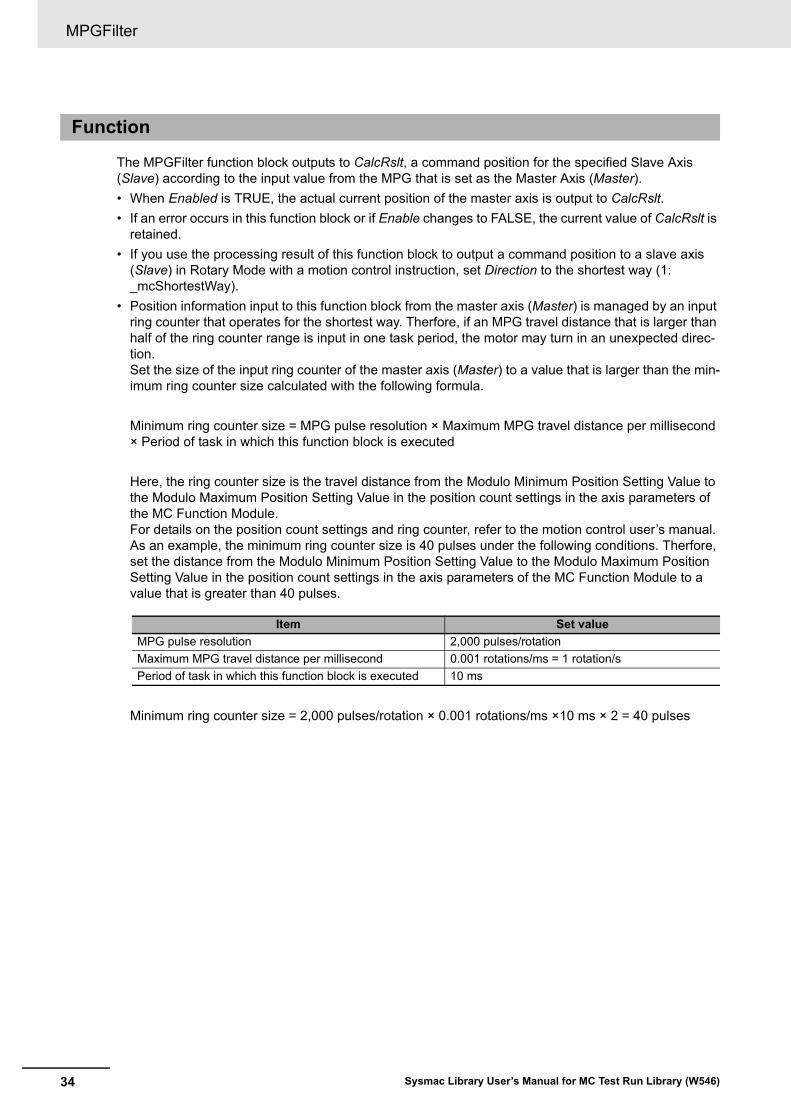
• Position information input to this function block from the master axis (Master) is managed by an input ring counter that operates for the shortest way. Therfore, if an MPG travel distance that is larger than half of the ring counter range is input in one task period, the motor may turn in an unexpected direc-tion.Set the size of the input ring counter of the master axis (Master) to a value that is larger than the min-imum ring counter size calculated with the following formula.
Minimum ring counter size = MPG pulse resolution × Maximum MPG travel distance per millisecond × Period of task in which this function block is executed
Here, the ring counter size is the travel distance from the Modulo Minimum Position Setting Value to the Modulo Maximum Position Setting Value in the position count settings in the axis parameters of the MC Function Module.For details on the position count settings and ring counter, refer to the motion control user’s manual.As an example, the minimum ring counter size is 40 pulses under the following conditions. Therfore, set the distance from the Modulo Minimum Position Setting Value to the Modulo Maximum Position Setting Value in the position count settings in the axis parameters of the MC Function Module to a value that is greater than 40 pulses.
Minimum ring counter size = 2,000 pulses/rotation × 0.001 rotations/ms ×10 ms × 2 = 40 pulses
Function
Item Set value
MPG pulse resolution 2,000 pulses/rotation
Maximum MPG travel distance per millisecond 0.001 rotations/ms = 1 rotation/s
Period of task in which this function block is executed 10 ms
35
MPGFilter
Sysmac Library User’s Manual for MC Test Run Library (W546)
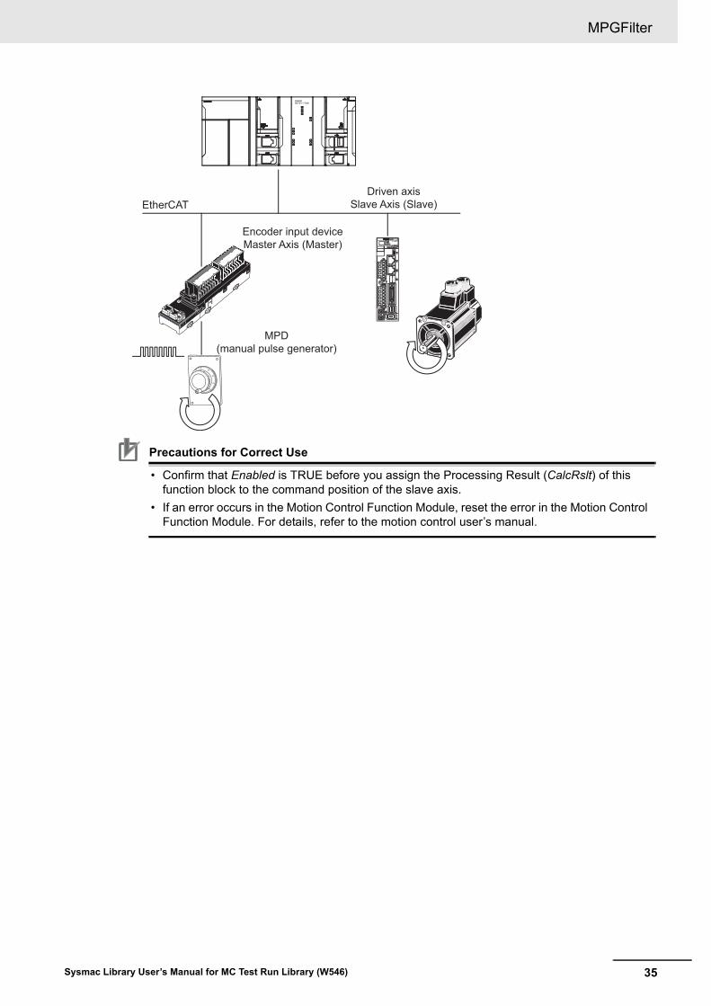
Precautions for Correct Use
• Confirm that Enabled is TRUE before you assign the Processing Result (CalcRslt) of this function block to the command position of the slave axis.
• If an error occurs in the Motion Control Function Module, reset the error in the Motion Control Function Module. For details, refer to the motion control user’s manual.
EtherCATDriven axis
Slave Axis (Slave)
Encoder input device Master Axis (Master)
MPD (manual pulse generator)

MPGFilter
36 Sysmac Library User’s Manual for MC Test Run Library (W546)
MPG Set Gear Ratios (MPGSetRatios)
You can set four ratios in MPG Set Gear Ratios (MPGSetRatios). The values that are set in MPGSe-tRatios when Enable changes to TRUE are used.
The default values in MPGSetRatios are 0. Always set values before you use MPGSetRatios.
Select the gear ratio with MP Gear Ratio (MPGOprRatio). If the numerator or denominator of the gear ratio selected with MPGOprRatio is 0, an error will occur. You can change the value of MPGO-prRatio at any time while this function block is enabled.
Name Meaning Description Data type Valid range UnitInitial value
MPGSetRatios MPG Set Gear Ratios
Set the four gear ratios used by the MPG.
OmronLib\MC_TestRun\sMPG_SET_RATIOS
--- --- ---
Ratio1_Num First Gear Ratio Numerator
Set the numerator of the first gear ratio.
DINT -10,000 to 10,000
0
Ratio1_Den First Gear Ratio Denominator
Set the denominator of the first gear ratio.
DINT 1 to 10,000 0
Ratio2_Num Second Gear Ratio Numera-tor
Set the numerator of the second gear ratio.
DINT -10,000 to 10,000
0
Ratio2_Den Second Gear Ratio Denomi-nator
Set the denominator of the second gear ratio.
DINT 1 to 10,000 0
Ratio3_Num Third Gear Ratio Numera-tor
Set the numerator of the third gear ratio.
DINT -10,000 to 10,000
0
Ratio3_Den Third Gear Ratio Denomi-nator
Set the denominator of the third gear ratio.
DINT 1 to 10,000 0
Ratio4_Num Fourth Gear Ratio Numera-tor
Set the numerator of the fourth gear ratio.
DINT -10,000 to 10,000
0
Ratio4_Den Fourth Gear Ratio Denomi-nator
Set the denominator of the fourth gear ratio.
DINT 1 to 10,000 0
37
MPGFilter
Sysmac Library User’s Manual for MC Test Run Library (W546)
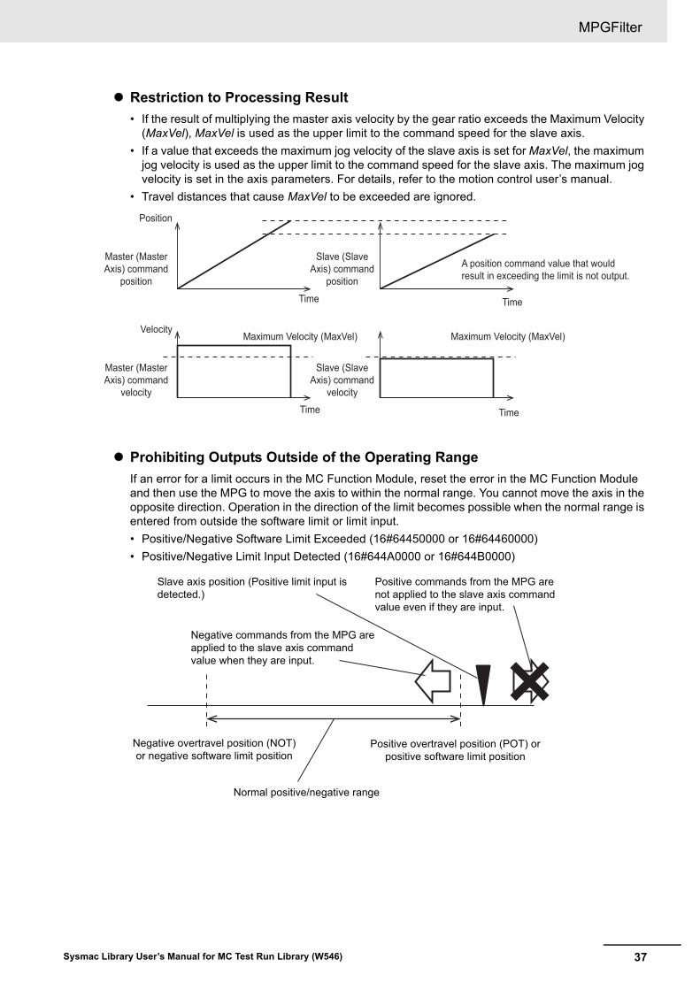
Restriction to Processing Result
• If the result of multiplying the master axis velocity by the gear ratio exceeds the Maximum Velocity (MaxVel), MaxVel is used as the upper limit to the command speed for the slave axis.
• If a value that exceeds the maximum jog velocity of the slave axis is set for MaxVel, the maximum jog velocity is used as the upper limit to the command speed for the slave axis. The maximum jog velocity is set in the axis parameters. For details, refer to the motion control user’s manual.
• Travel distances that cause MaxVel to be exceeded are ignored.
Prohibiting Outputs Outside of the Operating Range
If an error for a limit occurs in the MC Function Module, reset the error in the MC Function Module and then use the MPG to move the axis to within the normal range. You cannot move the axis in the opposite direction. Operation in the direction of the limit becomes possible when the normal range is entered from outside the software limit or limit input.
• Positive/Negative Software Limit Exceeded (16#64450000 or 16#64460000)
• Positive/Negative Limit Input Detected (16#644A0000 or 16#644B0000)
Position
Master (Master Axis) command
position
Slave (Slave Axis) command
position
A position command value that would result in exceeding the limit is not output.
Time
VelocityMaximum Velocity (MaxVel) Maximum Velocity (MaxVel)
Master (Master Axis) command
velocity
Slave (Slave Axis) command
velocity
Time
Time
Time
Slave axis position (Positive limit input is detected.)
Normal positive/negative range
Negative commands from the MPG are applied to the slave axis command value when they are input.
Negative overtravel position (NOT) or negative software limit position
Positive overtravel position (POT) or positive software limit position
Positive commands from the MPG are not applied to the slave axis command value even if they are input.
MPGFilter
38 Sysmac Library User’s Manual for MC Test Run Library (W546)
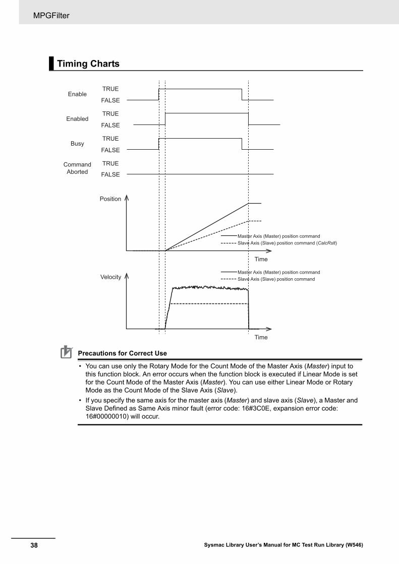
Precautions for Correct Use
• You can use only the Rotary Mode for the Count Mode of the Master Axis (Master) input to this function block. An error occurs when the function block is executed if Linear Mode is set for the Count Mode of the Master Axis (Master). You can use either Linear Mode or Rotary Mode as the Count Mode of the Slave Axis (Slave).
• If you specify the same axis for the master axis (Master) and slave axis (Slave), a Master and Slave Defined as Same Axis minor fault (error code: 16#3C0E, expansion error code: 16#00000010) will occur.
Timing Charts
EnableTRUE
FALSE
TRUE
FALSE
TRUE
FALSE
TRUE
Enabled
Busy
CommandAborted FALSE
Position
Time
Master Axis (Master) position commandSlave Axis (Slave) position command (CalcRslt)
Velocity
Time
Master Axis (Master) position commandSlave Axis (Slave) position command
39
MPGFilter
Sysmac Library User’s Manual for MC Test Run Library (W546)
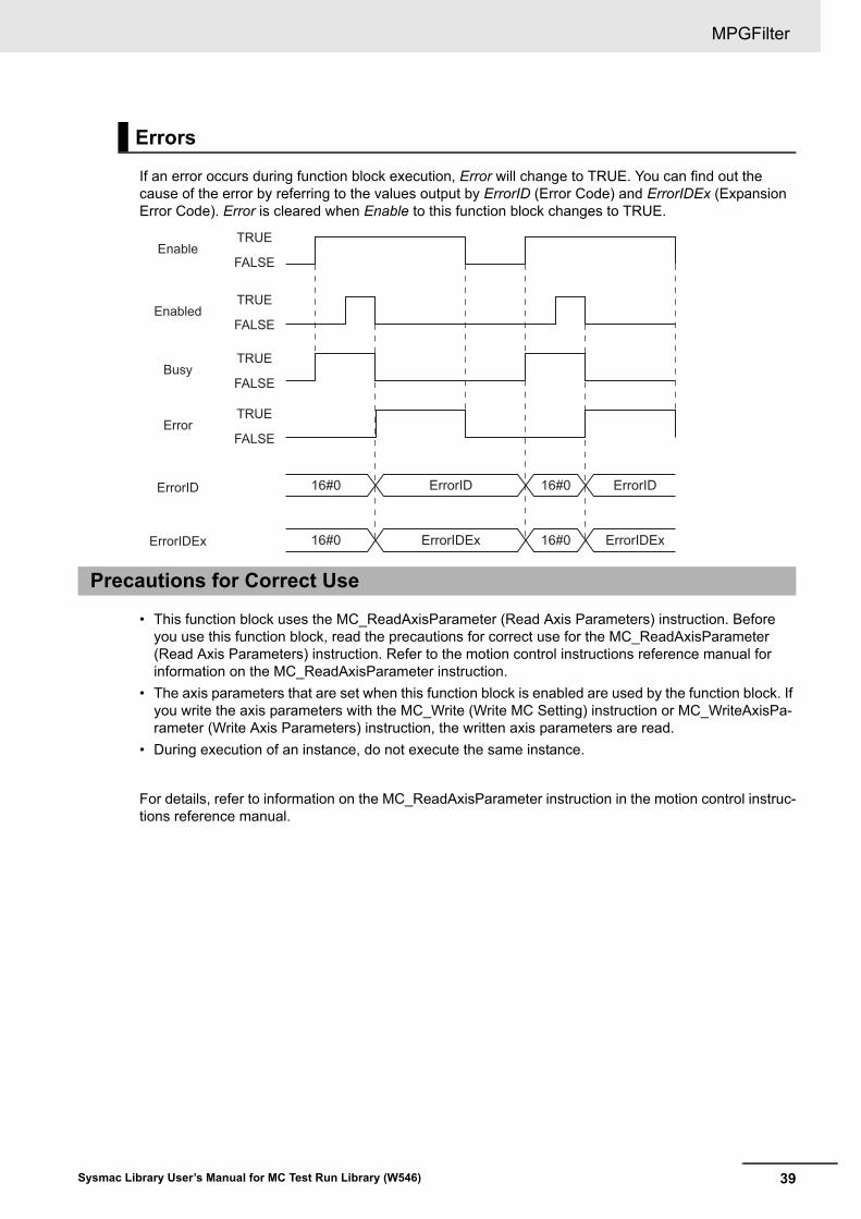
If an error occurs during function block execution, Error will change to TRUE. You can find out the cause of the error by referring to the values output by ErrorID (Error Code) and ErrorIDEx (Expansion Error Code). Error is cleared when Enable to this function block changes to TRUE.
• This function block uses the MC_ReadAxisParameter (Read Axis Parameters) instruction. Before you use this function block, read the precautions for correct use for the MC_ReadAxisParameter (Read Axis Parameters) instruction. Refer to the motion control instructions reference manual for information on the MC_ReadAxisParameter instruction.
• The axis parameters that are set when this function block is enabled are used by the function block. If you write the axis parameters with the MC_Write (Write MC Setting) instruction or MC_WriteAxisPa-rameter (Write Axis Parameters) instruction, the written axis parameters are read.
• During execution of an instance, do not execute the same instance.
For details, refer to information on the MC_ReadAxisParameter instruction in the motion control instruc-tions reference manual.
Errors
Precautions for Correct Use
16#0 ErrorIDEx 16#0 ErrorIDEx
16#0 ErrorID 16#0 ErrorID
EnableTRUE
FALSE
EnabledTRUE
FALSE
BusyTRUE
FALSE
ErrorTRUE
FALSE
ErrorID
ErrorIDEx

MPGFilter
40 Sysmac Library User’s Manual for MC Test Run Library (W546)
Troubleshooting
Error codeExpansion error
codeStatus (event
name)Description Correction
16#0000 16#00000000 Normal end --- ---16#3C0E 16#00000001 Input Value Out of
RangeThe MPGSetRatios input parameter for this function block exceeded the valid range for the input variable.
Correct the value set for MPGSetRatios so that it is within the valid range.
16#3C0E 16#00000002 Input Value Out of Range
The MaxVel input parameter for this function block exceeded the valid range for the input variable.
Correct the value set for Max-Vel so that it is within the valid range.
16#3C0E 16#00000003 Instruction Execu-tion Error Caused by Count Mode Setting
A Counter Mode other than Rotary Mode was specified for the axis specified with Master.
Set the axis specified with Master to Rotary Mode.
16#3C0E 16#00000004 Master Axis Type Error
The axis type of the axis speci-fied with Master is not set to an encoder axis or a virtual encoder axis.
Specify an encoder axis or a virtual encoder axis for the axis type of the axis specified with Master.
16#3C0E 16#00000005 Slave Axis Type Error
The axis type of the axis speci-fied with Slave is not set to a servo axis or a virtual servo axis.
Set the axis specified with Slave to a servo axis or a vir-tual servo axis.
16#3C0E 16#00000007 MPG Gear Ratio Error
The axis specified for the MPGOprRatio input variable to the function block is out of range.
Correct the value set for MPGOprRatio so that it is within the valid range.
16#3C0E 16#00000008 MPG Output Posi-tion Overflow
An overflow occurred in the processing result (i.e., the slave axis command position) for this function block.
Make corrections so that the slave axis position does not overflow.
16#3C0E 16#00000009 MPG Output Posi-tion Underflow
An underflow occurred in the processing result (i.e., the slave axis command position) for this function block.
Make corrections so that the slave axis position does not underflow.
16#3C0E 16#00000010 Master and Slave Defined as Same Axis
The same axis is specified for the Master and Slave input variables to this function block.
Correct the parameters so that different axes are specified for the Master and Slave input variables to the instruction.
16#3C0E 16#00000011 Master Axis Parameter Read Failure
A failure occurred in reading the master axis parameters for the MC_ReadAxisParameter instruction that is used in this function block.
Remove the cause of the error according to the event code for the MC_ReadAxisParameter (Read Axis Parameters) instruction.
16#3C0E 16#00000012 Slave Axis Param-eter Read Failure
A failure occurred in reading the slave axis parameters for the MC_ReadAxisParameter instruction that is used in this function block.
Remove the cause of the error according to the event code for the MC_ReadAxisParameter (Read Axis Parameters) instruction.
41
MPGFilter
Sysmac Library User’s Manual for MC Test Run Library (W546)
This sample programming operates a servomotor based on a pulse signal input from an MPG.
Precautions for Correct Use
• The sample programming shows only the portion of a program that uses the function or func-tion block from the library.
• When using actual devices, also program safety circuits, device interlocks, I/O with other devices, and other control procedures.
• Create a user program that will produce the intended device operation.
• Check the user program for proper execution before you use it for actual operation.
• An MPG is assigned to an encoder axis in the Motion Control Function Module. It is used as the mas-ter axis. The Axis Variable is MC_Axis000.
• The servomotor is assigned to a servo axis and used as the slave axis. The Axis Variable is MC_Ax-is001.
• The first to fourth gear ratios are set to the following values (numerator, denominator) = (1,1), (10,1), (100,1), and (1000,1).
• The Second Gear Ratio (10,1) is used.
1 Confirm that the slave axis can communicate and then turn ON the servo for the slave axis.
2 Confirm that the master axis can communicate and that an error has not occurred in the slave axis, and then enable the MPGFilter function block.
3 If the MPGFilter function block is enabled and the slave axis status is Standstill, execute the MC_SyncMoveAbsolute instruction for the slave axis. Assign the processing result CalcPosition from the MPGFilter function block to the command position.
4 If an error occurs in the MPGFilter function block, execute the MC_ImmediateStop instruction for the slave axis.
5 If an error occurs in the slave axis, receive the reset command and execute the MC_Reset instruction for the slave axis.
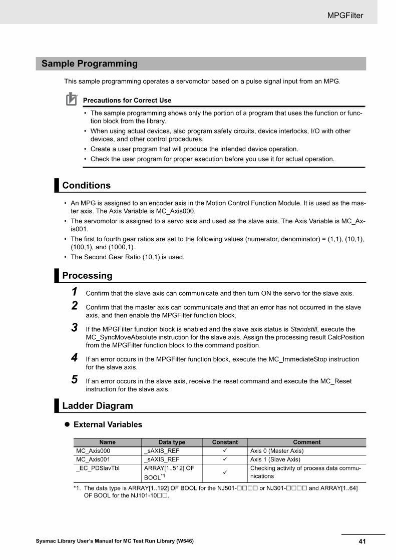
External Variables
Sample Programming
Conditions
Processing
Ladder Diagram
Name Data type Constant Comment
MC_Axis000 _sAXIS_REF Axis 0 (Master Axis)
MC_Axis001 _sAXIS_REF Axis 1 (Slave Axis)
_EC_PDSlavTbl ARRAY[1..512] OF
BOOL*1
*1. The data type is ARRAY[1..192] OF BOOL for the NJ501- or NJ301- and ARRAY[1..64] OF BOOL for the NJ101-10.
Checking activity of process data commu-nications
MPGFilter
42 Sysmac Library User’s Manual for MC Test Run Library (W546)
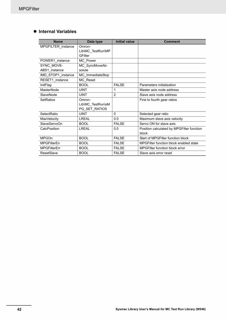
Internal Variables
Name Data type Initial value Comment
MPGFILTER_instance Omron-Lib\MC_TestRun\MPGFilter
POWER1_instance MC_Power
SYNC_MOVE-ABS1_instance
MC_SyncMoveAb-solute
IMD_STOP1_instance MC_ImmediateStop
RESET1_instance MC_Reset
InitFlag BOOL FALSE Parameters initialization
MasterNode UINT 1 Master axis node address
SlaveNode UINT 2 Slave axis node address
SetRatios Omron-Lib\MC_TestRun\sMPG_SET_RATIOS
First to fourth gear ratios
SelectRatio UINT 0 Selected gear ratio
MaxVelocity LREAL 0.0 Maximum slave axis velocity
SlaveServoOn BOOL FALSE Servo ON for slave axis
CalcPosition LREAL 0.0 Position calculated by MPGFilter function block
MPGOn BOOL FALSE Start of MPGFilter function block
MPGFilterEn BOOL FALSE MPGFilter function block enabled state
MPGFilterErr BOOL FALSE MPGFilter function block error
ResetSlave BOOL FALSE Slave axis error reset
43
MPGFilter
Sysmac Library User’s Manual for MC Test Run Library (W546)
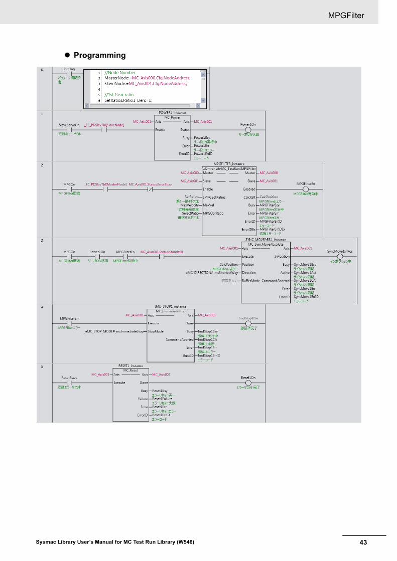
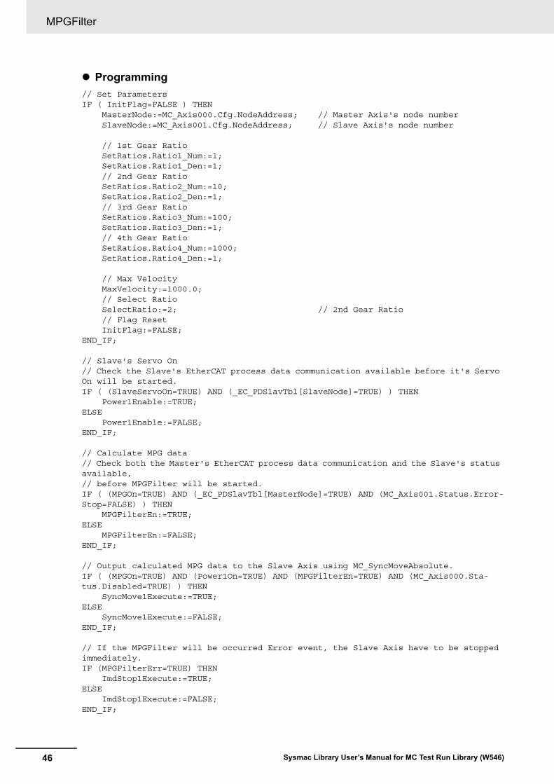
Programming
MPGFilter
44 Sysmac Library User’s Manual for MC Test Run Library (W546)
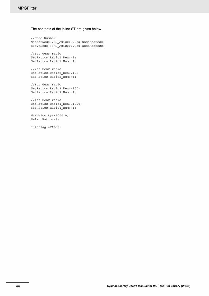
The contents of the inline ST are given below.
//Node NumberMasterNode:=MC_Axis000.Cfg.NodeAddress;SlaveNode :=MC_Axis001.Cfg.NodeAddress;
//1st Gear ratioSetRatios.Ratio1_Den:=1;SetRatios.Ratio1_Num:=1;
//2st Gear ratioSetRatios.Ratio2_Den:=10;SetRatios.Ratio2_Num:=1;
//3st Gear ratioSetRatios.Ratio3_Den:=100;SetRatios.Ratio3_Num:=1;
//4st Gear ratioSetRatios.Ratio4_Den:=1000;SetRatios.Ratio4_Num:=1;
MaxVelocity:=1000.0;SelectRatio:=2;
InitFlag:=FALSE;
45
MPGFilter
Sysmac Library User’s Manual for MC Test Run Library (W546)
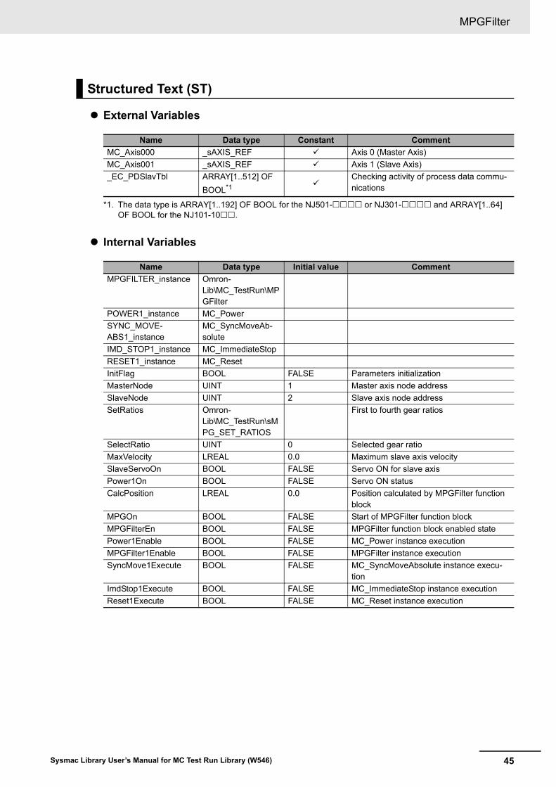
External Variables
Internal Variables
Structured Text (ST)
Name Data type Constant Comment
MC_Axis000 _sAXIS_REF Axis 0 (Master Axis)
MC_Axis001 _sAXIS_REF Axis 1 (Slave Axis)
_EC_PDSlavTbl ARRAY[1..512] OF
BOOL*1
*1. The data type is ARRAY[1..192] OF BOOL for the NJ501- or NJ301- and ARRAY[1..64] OF BOOL for the NJ101-10.
Checking activity of process data commu-nications
Name Data type Initial value Comment
MPGFILTER_instance Omron-Lib\MC_TestRun\MPGFilter
POWER1_instance MC_Power
SYNC_MOVE-ABS1_instance
MC_SyncMoveAb-solute
IMD_STOP1_instance MC_ImmediateStop
RESET1_instance MC_Reset
InitFlag BOOL FALSE Parameters initialization
MasterNode UINT 1 Master axis node address
SlaveNode UINT 2 Slave axis node address
SetRatios Omron-Lib\MC_TestRun\sMPG_SET_RATIOS
First to fourth gear ratios
SelectRatio UINT 0 Selected gear ratio
MaxVelocity LREAL 0.0 Maximum slave axis velocity
SlaveServoOn BOOL FALSE Servo ON for slave axis
Power1On BOOL FALSE Servo ON status
CalcPosition LREAL 0.0 Position calculated by MPGFilter function block
MPGOn BOOL FALSE Start of MPGFilter function block
MPGFilterEn BOOL FALSE MPGFilter function block enabled state
Power1Enable BOOL FALSE MC_Power instance execution
MPGFilter1Enable BOOL FALSE MPGFilter instance execution
SyncMove1Execute BOOL FALSE MC_SyncMoveAbsolute instance execu-tion
ImdStop1Execute BOOL FALSE MC_ImmediateStop instance execution
Reset1Execute BOOL FALSE MC_Reset instance execution
MPGFilter
46 Sysmac Library User’s Manual for MC Test Run Library (W546)
Programming
// Set ParametersIF ( InitFlag=FALSE ) THEN MasterNode:=MC_Axis000.Cfg.NodeAddress; // Master Axis's node number SlaveNode:=MC_Axis001.Cfg.NodeAddress; // Slave Axis's node number
// 1st Gear Ratio SetRatios.Ratio1_Num:=1; SetRatios.Ratio1_Den:=1; // 2nd Gear Ratio SetRatios.Ratio2_Num:=10; SetRatios.Ratio2_Den:=1; // 3rd Gear Ratio SetRatios.Ratio3_Num:=100; SetRatios.Ratio3_Den:=1; // 4th Gear Ratio SetRatios.Ratio4_Num:=1000; SetRatios.Ratio4_Den:=1;
// Max Velocity MaxVelocity:=1000.0; // Select Ratio SelectRatio:=2; // 2nd Gear Ratio // Flag Reset InitFlag:=FALSE;END_IF;
// Slave's Servo On // Check the Slave's EtherCAT process data communication available before it's Servo On will be started.IF ( (SlaveServoOn=TRUE) AND (_EC_PDSlavTbl[SlaveNode]=TRUE) ) THEN Power1Enable:=TRUE;ELSE Power1Enable:=FALSE;END_IF;
// Calculate MPG data// Check both the Master's EtherCAT process data communication and the Slave's status available,// before MPGFilter will be started.IF ( (MPGOn=TRUE) AND (_EC_PDSlavTbl[MasterNode]=TRUE) AND (MC_Axis001.Status.Error-Stop=FALSE) ) THEN MPGFilterEn:=TRUE;ELSE MPGFilterEn:=FALSE;END_IF;
// Output calculated MPG data to the Slave Axis using MC_SyncMoveAbsolute.IF ( (MPGOn=TRUE) AND (Power1On=TRUE) AND (MPGFilterEn=TRUE) AND (MC_Axis000.Sta-tus.Disabled=TRUE) ) THEN SyncMove1Execute:=TRUE;ELSE SyncMove1Execute:=FALSE;END_IF;
// If the MPGFilter will be occurred Error event, the Slave Axis have to be stopped immediately.IF (MPGFilterErr=TRUE) THEN ImdStop1Execute:=TRUE;ELSE ImdStop1Execute:=FALSE;END_IF;
47
MPGFilter
Sysmac Library User’s Manual for MC Test Run Library (W546)
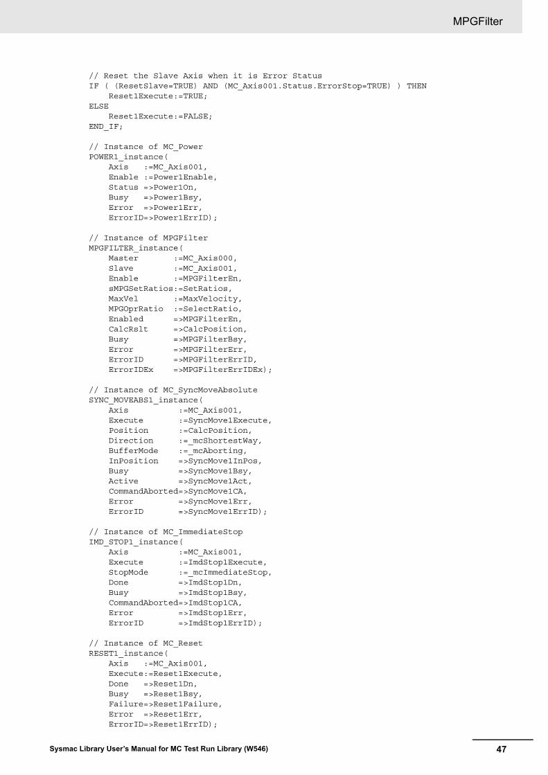
// Reset the Slave Axis when it is Error StatusIF ( (ResetSlave=TRUE) AND (MC_Axis001.Status.ErrorStop=TRUE) ) THEN Reset1Execute:=TRUE;ELSE Reset1Execute:=FALSE;END_IF;
// Instance of MC_PowerPOWER1_instance( Axis :=MC_Axis001, Enable :=Power1Enable, Status =>Power1On, Busy =>Power1Bsy, Error =>Power1Err, ErrorID=>Power1ErrID);
// Instance of MPGFilterMPGFILTER_instance( Master :=MC_Axis000, Slave :=MC_Axis001, Enable :=MPGFilterEn, sMPGSetRatios:=SetRatios, MaxVel :=MaxVelocity, MPGOprRatio :=SelectRatio, Enabled =>MPGFilterEn, CalcRslt =>CalcPosition, Busy =>MPGFilterBsy, Error =>MPGFilterErr, ErrorID =>MPGFilterErrID, ErrorIDEx =>MPGFilterErrIDEx);
// Instance of MC_SyncMoveAbsoluteSYNC_MOVEABS1_instance( Axis :=MC_Axis001, Execute :=SyncMove1Execute, Position :=CalcPosition, Direction :=_mcShortestWay, BufferMode :=_mcAborting, InPosition =>SyncMove1InPos, Busy =>SyncMove1Bsy, Active =>SyncMove1Act, CommandAborted=>SyncMove1CA, Error =>SyncMove1Err, ErrorID =>SyncMove1ErrID);
// Instance of MC_ImmediateStopIMD_STOP1_instance( Axis :=MC_Axis001, Execute :=ImdStop1Execute, StopMode :=_mcImmediateStop, Done =>ImdStop1Dn, Busy =>ImdStop1Bsy, CommandAborted=>ImdStop1CA, Error =>ImdStop1Err, ErrorID =>ImdStop1ErrID);
// Instance of MC_ResetRESET1_instance( Axis :=MC_Axis001, Execute:=Reset1Execute, Done =>Reset1Dn, Busy =>Reset1Bsy, Failure=>Reset1Failure, Error =>Reset1Err, ErrorID=>Reset1ErrID);
MPGFilter
48 Sysmac Library User’s Manual for MC Test Run Library (W546)
49Sysmac Library User’s Manual for MC Test Run Library (W546)
Appendix
Referring to Library Information
50 Sysmac Library User’s Manual for MC Test Run Library (W546)
Referring to Library Information
When you make an inquiry to OMRON about the library, you can refer to the library information to iden-tify the library to ask about.
The library information is useful in identifying the target library among the libraries provided by OMRON or created by the user.
The library information consists of the attributes of the library and the attributes of function blocks and functions contained in the library.
• Attributes of libraries
Information for identifying the library itself
• Attributes of function blocks and functions
Information for identifying the function block and function contained in the library
Use the Sysmac Studio to access the library information.
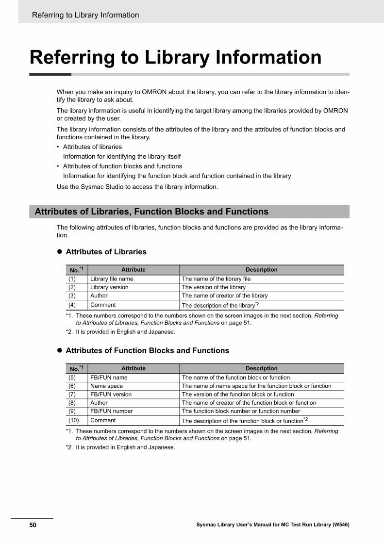
The following attributes of libraries, function blocks and functions are provided as the library informa-tion.
Attributes of Libraries
Attributes of Function Blocks and Functions
Attributes of Libraries, Function Blocks and Functions
No.*1
*1. These numbers correspond to the numbers shown on the screen images in the next section, Referring to Attributes of Libraries, Function Blocks and Functions on page 51.
Attribute Description
(1) Library file name The name of the library file
(2) Library version The version of the library
(3) Author The name of creator of the library
(4) Comment The description of the library*2
*2. It is provided in English and Japanese.
No.*1
*1. These numbers correspond to the numbers shown on the screen images in the next section, Referring to Attributes of Libraries, Function Blocks and Functions on page 51.
Attribute Description
(5) FB/FUN name The name of the function block or function
(6) Name space The name of name space for the function block or function
(7) FB/FUN version The version of the function block or function
(8) Author The name of creator of the function block or function
(9) FB/FUN number The function block number or function number
(10) Comment The description of the function block or function*2
*2. It is provided in English and Japanese.

51
Referring to Library Information
Sysmac Library User’s Manual for MC Test Run Library (W546)
You can refer to the attributes of libraries, function blocks and functions of the library information at the following locations on the Sysmac Studio.
• Library Reference Dialog Box
• Toolbox Pane
• Ladder Editor
(a) Library Reference Dialog Box
When you refer to the libraries, the library information is displayed at the locations shown below.
Referring to Attributes of Libraries, Function Blocks and Functions
(2)Library version(1)Library file name (3)Library author (4)Library comment
(5)FB/FUN name
(7)FB/FUN version(8)FB/FUN author (10)FB/FUN comment
(6)Name space
Referring to Library Information
52 Sysmac Library User’s Manual for MC Test Run Library (W546)
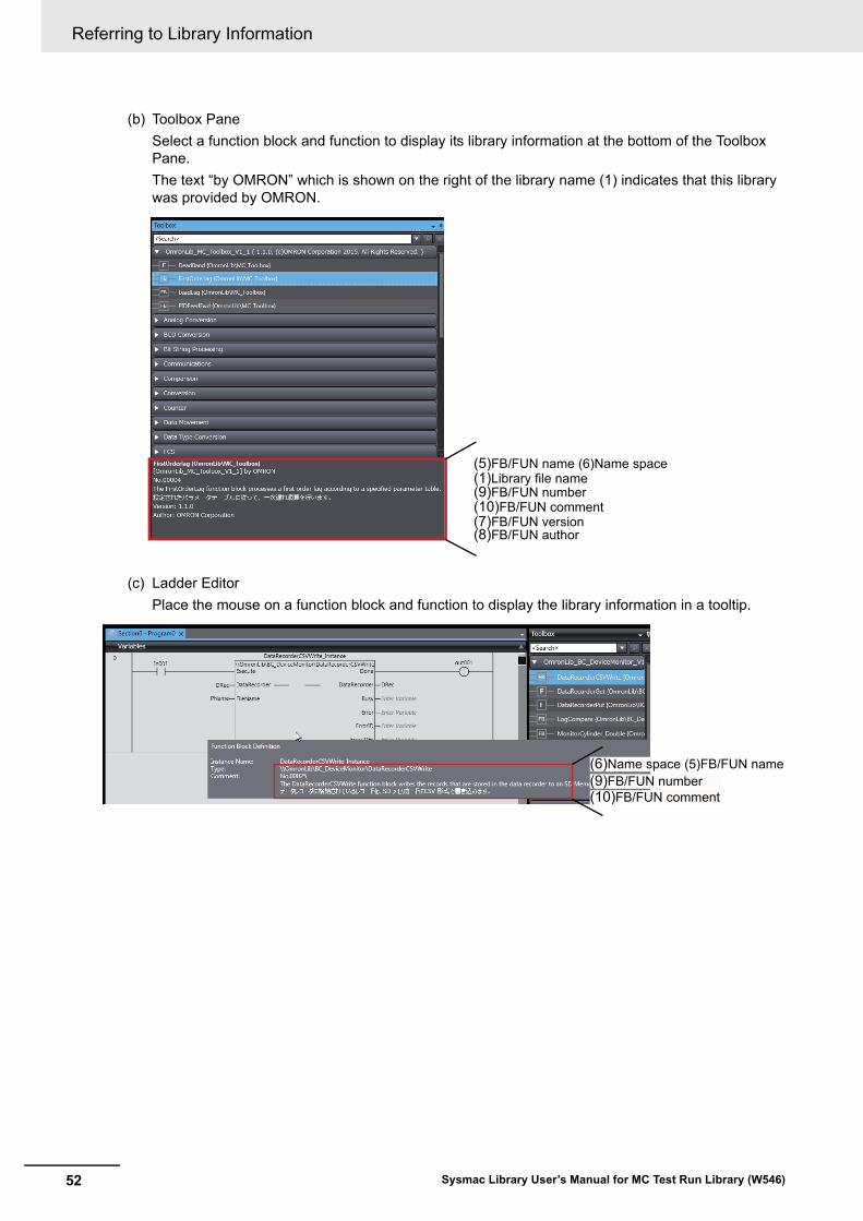
(b) Toolbox Pane
Select a function block and function to display its library information at the bottom of the Toolbox Pane.
The text “by OMRON” which is shown on the right of the library name (1) indicates that this library was provided by OMRON.
(c) Ladder Editor
Place the mouse on a function block and function to display the library information in a tooltip.
(5)FB/FUN name (6)Name space(1)Library file name(9)FB/FUN number(10)FB/FUN comment(7)FB/FUN version(8)FB/FUN author
(6)Name space (5)FB/FUN name
(10)FB/FUN comment(9)FB/FUN number
53
Referring to Function Block and Function Source Codes
Sysmac Library User’s Manual for MC Test Run Library (W546)
Referring to Function Block and Function Source Codes
You can refer to the source codes of function blocks and functions provided by OMRON to customize them to suit the user’s environment.
User function blocks and user functions can be created based on the copies of these source codes.
The following are the examples of items that you may need to customize.
• Customizing the size of arrays to suit the memory capacity of the user’s Controller
• Customizing the data types to suit the user-defined data types
Note that you can access only function blocks and functions whose Source code published/not pub-lished is set to Published in the library information shown in their individual specifications.
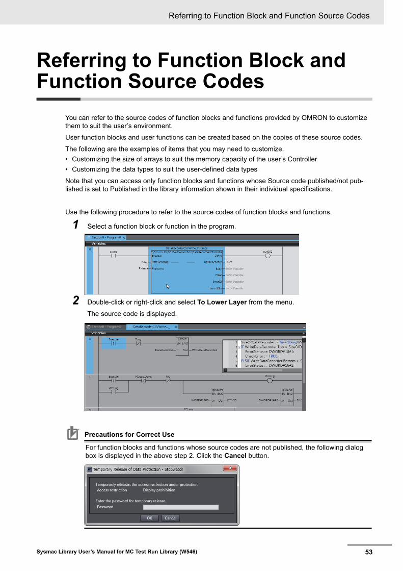
Use the following procedure to refer to the source codes of function blocks and functions.
1 Select a function block or function in the program.
2 Double-click or right-click and select To Lower Layer from the menu.
The source code is displayed.
Precautions for Correct Use
For function blocks and functions whose source codes are not published, the following dialog box is displayed in the above step 2. Click the Cancel button.
Referring to Function Block and Function Source Codes
54 Sysmac Library User’s Manual for MC Test Run Library (W546)

Authorized Distributor:
In the interest of product improvement, specifications are subject to change without notice.
Cat. No. W546-E1-04 1116
© OMRON Corporation 2015-2016 All Rights Reserved.
OMRON Corporation Industrial Automation Company
OMRON ELECTRONICS LLC2895 Greenspoint Parkway, Suite 200 Hoffman Estates, IL 60169 U.S.A.Tel: (1) 847-843-7900/Fax: (1) 847-843-7787
Regional HeadquartersOMRON EUROPE B.V.Wegalaan 67-69, 2132 JD HoofddorpThe NetherlandsTel: (31)2356-81-300/Fax: (31)2356-81-388
Contact: www.ia.omron.comKyoto, JAPAN
OMRON ASIA PACIFIC PTE. LTD.No. 438A Alexandra Road # 05-05/08 (Lobby 2), Alexandra Technopark, Singapore 119967Tel: (65) 6835-3011/Fax: (65) 6835-2711
OMRON (CHINA) CO., LTD.Room 2211, Bank of China Tower, 200 Yin Cheng Zhong Road, PuDong New Area, Shanghai, 200120, ChinaTel: (86) 21-5037-2222/Fax: (86) 21-5037-2200