system 60-2 autopilot pilot's operating handbook 60-2 autopilot pilot's operating...
TRANSCRIPT
System 60-2 AutopilotPilot's Operating
Handbook
2nd Ed: Nov 01, 01 i
SYS 60-2 POH
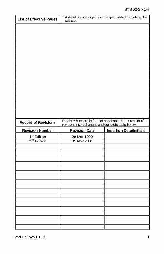
List of Effective Pages * Asterisk indicates pages changed, added, or deleted byrevision.
Record of Revisions Retain this record in front of handbook. Upon receipt of arevision, insert changes and complete table below.
Revision Number Revision Date Insertion Date/Initials
1st Edition 29 Mar 19992nd Edition 01 Nov 2001

ii 2nd Ed: Nov 01, 01
SYS 60-2 POH
Page Intentionally Blank
2nd Ed: Nov 01, 01 iii
SYS 60-2 POH
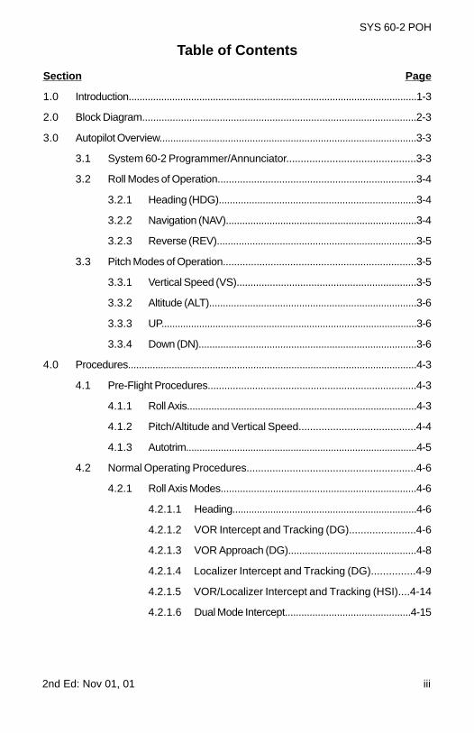
Table of Contents
Section Page
1.0 Introduction..........................................................................................................1-3
2.0 Block Diagram...................................................................................................2-3
3.0 Autopilot Overview..............................................................................................3-3
3.1 System 60-2 Programmer/Annunciator.............................................3-3
3.2 Roll Modes of Operation.......................................................................3-4
3.2.1 Heading (HDG)........................................................................3-4
3.2.2 Navigation (NAV)......................................................................3-4
3.2.3 Reverse (REV).........................................................................3-5
3.3 Pitch Modes of Operation.....................................................................3-5
3.3.1 Vertical Speed (VS).................................................................3-5
3.3.2 Altitude (ALT)............................................................................3-6
3.3.3 UP...............................................................................................3-6
3.3.4 Down (DN)................................................................................3-6
4.0 Procedures..........................................................................................................4-3
4.1 Pre-Flight Procedures...........................................................................4-3
4.1.1 Roll Axis.....................................................................................4-3
4.1.2 Pitch/Altitude and Vertical Speed.........................................4-4
4.1.3 Autotrim......................................................................................4-5
4.2 Normal Operating Procedures...........................................................4-6
4.2.1 Roll Axis Modes.......................................................................4-6
4.2.1.1 Heading....................................................................4-6
4.2.1.2 VOR Intercept and Tracking (DG).......................4-6
4.2.1.3 VOR Approach (DG)..............................................4-8
4.2.1.4 Localizer Intercept and Tracking (DG)...............4-9
4.2.1.5 VOR/Localizer Intercept and Tracking (HSI)....4-14
4.2.1.6 Dual Mode Intercept..............................................4-15
iv 2nd Ed: Nov 01, 01
SYS 60-2 POH
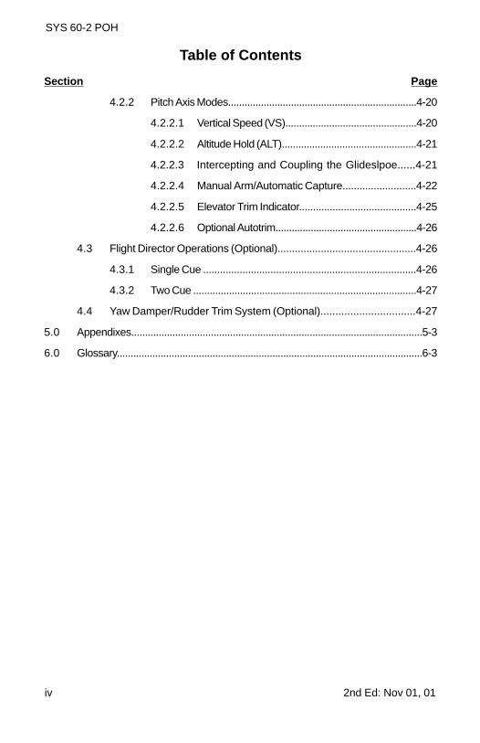
Table of Contents
Section Page
4.2.2 Pitch Axis Modes.....................................................................4-20
4.2.2.1 Vertical Speed (VS)................................................4-20
4.2.2.2 Altitude Hold (ALT).................................................4-21
4.2.2.3 Intercepting and Coupling the Glideslpoe......4-21
4.2.2.4 Manual Arm/Automatic Capture..........................4-22
4.2.2.5 Elevator Trim Indicator..........................................4-25
4.2.2.6 Optional Autotrim....................................................4-26
4.3 Flight Director Operations (Optional)................................................4-26
4.3.1 Single Cue ............................................................................4-26
4.3.2 Two Cue .................................................................................4-27
4.4 Yaw Damper/Rudder Trim System (Optional)................................4-27
5.0 Appendixes..........................................................................................................5-3
6.0 Glossary................................................................................................................6-3
2nd Ed: Nov 01, 01 v
SYS 60-2 POH
List of Figures
Figure Page
2-1 System 60-2 Block Diagram............................................................................2-3
3-1 System 60-2 Programmer/Annunciator.........................................................3-3
4-1 Directional Gyro..................................................................................................4-6
4-2 VOR/LOC/GPS.....................................................................................................4-8
4-3 Straight-In Localizer Approach and Tracking (DG).....................................4-10
4-4 Procedure Turn Localizer Approach and Tracking (DG)............................4-11
4-5 Back Course Straight-In Approach (DG)......................................................4-12
4-6 Back Course Procedure Turn (DG)..............................................................4-13
4-7 Horizontal Situation Indicator (HSI)...............................................................4-14
4-8 Straight-In Localizer Approach and Tracking (Optional HSI)....................4-16
4-9 Procedure Turn Localizer Approach and Tracking (Optional HSI)...........4-17
4-10 Back Course Straight-In Approach (Optional HSI).....................................4-18
4-11 Back Course Procedure Turn (Optional HSI).............................................4-19
4-12 Glideslope Intercept and Track......................................................................4-23
4-13 Procedure Turn for Glideslope Approach....................................................4-24

vi 2nd Ed: Nov 01, 01
SYS 60-2 POH
Page Intentionally Blank

2nd Ed: Nov 01, 01 1-1
SYS 60-2 POH
SECTION 1INTRODUCTION

1-2 2nd Ed: Nov 01, 01
SYS 60-2 POH
Page Intentionally Blank
2nd Ed: Nov 01, 01 1-3
SYS 60-2 POH
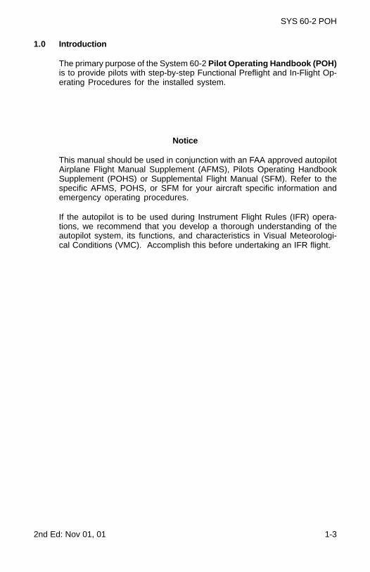
1.0 Introduction
The primary purpose of the System 60-2 Pilot Operating Handbook (POH)is to provide pilots with step-by-step Functional Preflight and In-Flight Op-erating Procedures for the installed system.
Notice
This manual should be used in conjunction with an FAA approved autopilotAirplane Flight Manual Supplement (AFMS), Pilots Operating HandbookSupplement (POHS) or Supplemental Flight Manual (SFM). Refer to thespecific AFMS, POHS, or SFM for your aircraft specific information andemergency operating procedures.
If the autopilot is to be used during Instrument Flight Rules (IFR) opera-tions, we recommend that you develop a thorough understanding of theautopilot system, its functions, and characteristics in Visual Meteorologi-cal Conditions (VMC). Accomplish this before undertaking an IFR flight.

1-4 2nd Ed: Nov 01, 01
SYS 60-2 POH
Page Intentionally Blank
2nd Ed: Nov 01, 01 2-1
SYS 60-2 POH
SECTION 2BLOCK DIAGRAM

2-2 2nd Ed: Nov 01, 01
SYS 60-2 POH
Page Intentionally Blank
2nd Ed: Nov 01, 01 2-3
SYS 60-2 POH
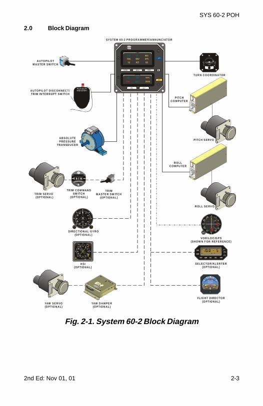
2.0 Block Diagram
Fig. 2-1. System 60-2 Block Diagram
T R I M
VO R /LO C /G P S(SH O W N F OR REF ER EN CE )
A UTO P ILO T D ISC ON N EC T /TR IM IN TE R R UPT SW ITCH
TR IM CO M MAN DSW ITCH
(O PT IO N A L)TR IM SER VO(O PT IO N A L)
A UTO P IL O TM A STE R SW ITC H
TR IMM A STE R SW ITC H
(O PT IO N A L)
SNAV
GS
H SI(O PT IO N A L)
PITC H S ERV O
TU R N C O O R DINATOR
D IR E C TIO N AL GY R O(O PT IO N A L)
A BS O L UTEPR E S SU RE
TR A N SD U CE R
P US H H DG
R O LL S E RV O
YAW S E RVO(O PT IO N A L)
YAW D A M PE R(O PT IO N A L)
NO
PITCH INFORMATI O
N
TURN COORDINATOR
2 MIN
FL IG HT DIRE CTO R(O PT IO N A L)
A/P DIS CTRIM INTRPT
R O LLC O M PU TE R
PITC HC O M PU TE R
SE LEC TO R/AL ER TE R(O PT IO N A L)
SY S TEM 60-2 P R O G RA M ME R/AN N UN CIATO R

2-4 2nd Ed: Nov 01, 01
SYS 60-2 POH
Page Intentionally Blank

2nd Ed: Nov 01, 01 3-1
SYS 60-2 POH
SECTION 3AUTOPILOT OVERVIEW

3-2 2nd Ed: Nov 01, 01
SYS 60-2 POH
Page Intentionally Blank
2nd Ed: Nov 01, 01 3-3
SYS 60-2 POH
3.0 Autopilot Overview
3.1 System 60-2 Programmer/Annunciator
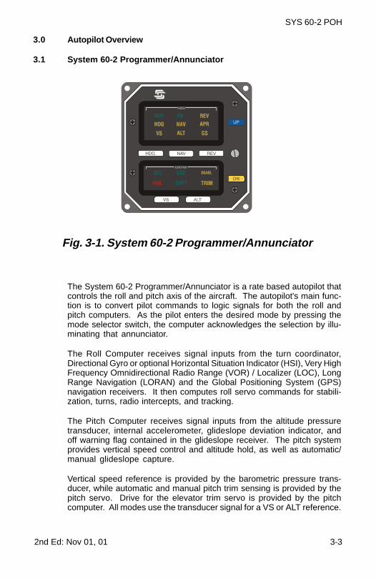
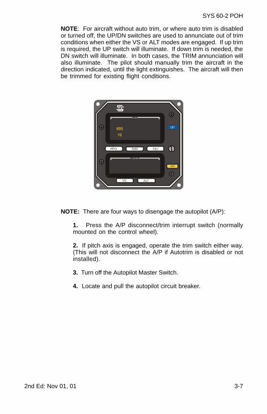
Fig. 3-1. System 60-2 Programmer/Annunciator
The System 60-2 Programmer/Annunciator is a rate based autopilot thatcontrols the roll and pitch axis of the aircraft. The autopilot's main func-tion is to convert pilot commands to logic signals for both the roll andpitch computers. As the pilot enters the desired mode by pressing themode selector switch, the computer acknowledges the selection by illu-minating that annunciator.
The Roll Computer receives signal inputs from the turn coordinator,Directional Gyro or optional Horizontal Situation Indicator (HSI), Very HighFrequency Omnidirectional Radio Range (VOR) / Localizer (LOC), LongRange Navigation (LORAN) and the Global Positioning System (GPS)navigation receivers. It then computes roll servo commands for stabili-zation, turns, radio intercepts, and tracking.
The Pitch Computer receives signal inputs from the altitude pressuretransducer, internal accelerometer, glideslope deviation indicator, andoff warning flag contained in the glideslope receiver. The pitch systemprovides vertical speed control and altitude hold, as well as automatic/manual glideslope capture.
Vertical speed reference is provided by the barometric pressure trans-ducer, while automatic and manual pitch trim sensing is provided by thepitch servo. Drive for the elevator trim servo is provided by the pitchcomputer. All modes use the transducer signal for a VS or ALT reference.
3-4 2nd Ed: Nov 01, 01
SYS 60-2 POH
3.2 Roll Modes of Operation
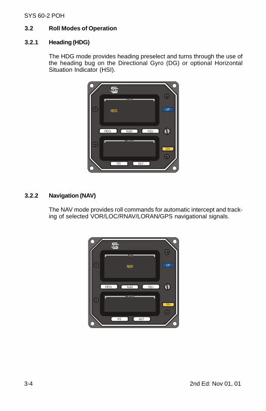
3.2.1 Heading (HDG)
The HDG mode provides heading preselect and turns through the use ofthe heading bug on the Directional Gyro (DG) or optional HorizontalSituation Indicator (HSI).
3.2.2 Navigation (NAV)
The NAV mode provides roll commands for automatic intercept and track-ing of selected VOR/LOC/RNAV/LORAN/GPS navigational signals.
2nd Ed: Nov 01, 01 3-5
SYS 60-2 POH
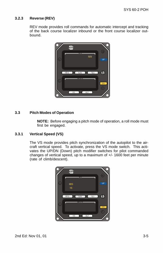
3.2.3 Reverse (REV)
REV mode provides roll commands for automatic intercept and trackingof the back course localizer inbound or the front course localizer out-bound.
3.3 Pitch Modes of Operation
NOTE: Before engaging a pitch mode of operation, a roll mode mustfirst be engaged.
3.3.1 Vertical Speed (VS)
The VS mode provides pitch synchronization of the autopilot to the air-craft vertical speed. To activate, press the VS mode switch. This acti-vates the UP/DN (Down) pitch modifier switches for pilot commandedchanges of vertical speed, up to a maximum of +/- 1600 feet per minute(rate of climb/descent).
3-6 2nd Ed: Nov 01, 01
SYS 60-2 POH
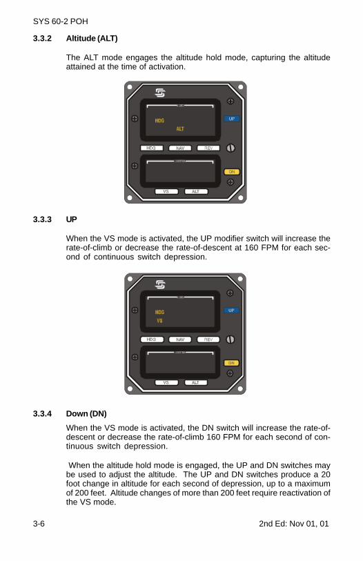
3.3.2 Altitude (ALT)
The ALT mode engages the altitude hold mode, capturing the altitudeattained at the time of activation.
3.3.3 UP
When the VS mode is activated, the UP modifier switch will increase therate-of-climb or decrease the rate-of-descent at 160 FPM for each sec-ond of continuous switch depression.
3.3.4 Down (DN)
When the VS mode is activated, the DN switch will increase the rate-of-descent or decrease the rate-of-climb 160 FPM for each second of con-tinuous switch depression.
When the altitude hold mode is engaged, the UP and DN switches maybe used to adjust the altitude. The UP and DN switches produce a 20foot change in altitude for each second of depression, up to a maximumof 200 feet. Altitude changes of more than 200 feet require reactivation ofthe VS mode.
2nd Ed: Nov 01, 01 3-7
SYS 60-2 POH
NOTE: For aircraft without auto trim, or where auto trim is disabledor turned off, the UP/DN switches are used to annunciate out of trimconditions when either the VS or ALT modes are engaged. If up trimis required, the UP switch will illuminate. If down trim is needed, theDN switch will illuminate. In both cases, the TRIM annunciation willalso illuminate. The pilot should manually trim the aircraft in thedirection indicated, until the light extinguishes. The aircraft will thenbe trimmed for existing flight conditions.
NOTE: There are four ways to disengage the autopilot (A/P):
1. Press the A/P disconnect/trim interrupt switch (normallymounted on the control wheel).
2. If pitch axis is engaged, operate the trim switch either way.(This will not disconnect the A/P if Autotrim is disabled or notinstalled).
3. Turn off the Autopilot Master Switch.
4. Locate and pull the autopilot circuit breaker.

3-8 2nd Ed: Nov 01, 01
SYS 60-2 POH
Page Intentionally Blank
2nd Ed: Nov 01, 01 4-1
SYS 60-2 POH
SECTION 4PROCEDURES

4-2 2nd Ed: Nov 01, 01
SYS 60-2 POH
Page Intentionally Blank
2nd Ed: Nov 01, 01 4-3
SYS 60-2 POH
4.0 Procedures
4.1 Pre-Flight Procedures
NOTE: To perform the system function check, adequate DC voltagemust be supplied to the system, either 12 or 24 VDC, depending onthe aircraft.
4.1.1 Roll Axis
The following is a step by step procedure for preflighting the Roll Axis:
1. Place the A/P Master Switch to the TEST position. This shouldresult in illumination of all annunciation’s: RDY, HDG, VS, FD, NAV,ALT, REV, APR, GS, SEL, UP, DN, FAIL, DSABL, TRIM, CAP, and SOFT.After all annunciation’s are observed, place the A/P Master Switch tothe ON position. If the Turn Coordinator gyro is up to speed, only theRDY annunciation should remain on.
2. Rotate the heading knob on the Directional Gyro (DG) to positionthe bug under the lubber line.
3. Engage the HDG mode, and observe the HDG annunciation. Thenmove the DG heading knob left and right. The control wheel shouldmove in the direction of bug travel. Return the bug to center.
4. Grasp the control wheel and manually turn it left and right tooverpower the roll servo. There should be a noticeable increase incontrol wheel friction, no excessive looseness, no ratcheting or noise.
5. Turn on the NAV radio and tune a valid VOR signal. Then engagethe NAV mode, observing the NAV annunciation. Move the VOR/OBSso that the needle swings left and right. The control wheel shouldmove in the direction of needle travel. The NAV annunciation shouldflash when CDI deflection is over 50%.
6. Select REV mode, and observe the REV annunciation. Again,rotate the VOR/OBS knob. The control wheel should move oppositethe direction of needle travel. The NAV annunciation should flashwhen CDI deflection is over 50%.
7. Channel a nonvalid VOR signal. The NAV annunciation shouldflash, and FAIL annunciation should illuminate (if the radio has aNAV flag output).
8. Disconnect by pressing and releasing the control wheel mountedA/P disconnect switch. Move the control wheel to ensure freedom ofcontrols, and check to see that the RDY annunciator is flashing forapproximately 5 seconds to indicate autopilot disconnect.
4-4 2nd Ed: Nov 01, 01
SYS 60-2 POH
4.1.2 Pitch/Altitude and Vertical Speed
The following is a step by step procedure for pre-flighting the Pitch/Altitude and Vertical Speed Systems:
1. Be sure the Autopilot Master Switch is ON, and that a roll axismode has been selected.
2. Move the control wheel to level flight position and engage the VSmode. Press the UP modifier switch and hold. The control wheelshould move aft, slowly. Press the DN switch and hold. The controlwheel should move slowly forward.
NOTE: On some aircraft the autopilot may not be able to lift theelevators without pilot assistance during ground operation.
3. Overpower the pitch function by pulling the control wheel slowlyaft. The TRIM annunciator and DN switch should illuminate and theaudio warning should sound. Slowly push the control wheel forward.The TRIM annunciation and UP switch should illuminate and audiowarning should sound. During overpower, there should be noexcessive play in the controls or ratcheting noise.
4. Pitch Limiter Test:
A. Place the Master Switch to TEST position.
B. Engage HDG mode.
C. Engage ALT mode.
D. Center and hold the control wheel, press and hold the UPswitch. Pitch should disengage after about .5 seconds, releaseUP switch, pitch should reengage.
E. Hold the control wheel, press and hold the DN switch. Pitchshould disengage after about .5 seconds, release DN switch,pitch should reengage.
CAUTIONIf the pitch servo does not disengage when either the UP orDN modifier switch is engaged, the limit accelerometer mayhave failed. Do not use the autopilot pitch section until theproblem is corrected. This check should be performed onceper flight day. (Check FAA approved AFM supplement.)
NOTE: If optional autotrim is not installed, this is the end of thepreflight test. Press and release the disconnect switch on thecontrol wheel, and place the Autopilot Master Switch in the OFFor ON position. Move aircraft controls to ensure freedom ofmovement and to make sure the autopilot has disconnected.
2nd Ed: Nov 01, 01 4-5
SYS 60-2 POH
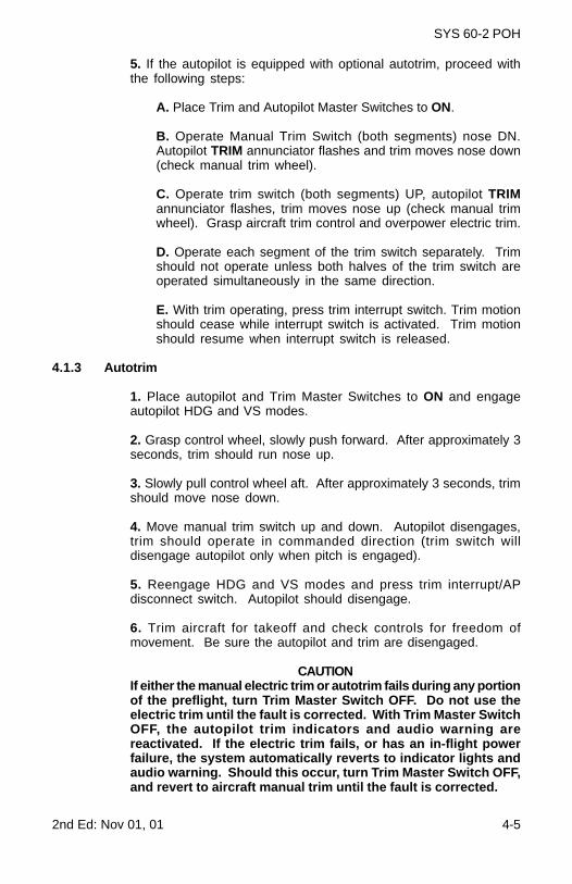
5. If the autopilot is equipped with optional autotrim, proceed withthe following steps:
A. Place Trim and Autopilot Master Switches to ON.
B. Operate Manual Trim Switch (both segments) nose DN.Autopilot TRIM annunciator flashes and trim moves nose down(check manual trim wheel).
C. Operate trim switch (both segments) UP, autopilot TRIMannunciator flashes, trim moves nose up (check manual trimwheel). Grasp aircraft trim control and overpower electric trim.
D. Operate each segment of the trim switch separately. Trimshould not operate unless both halves of the trim switch areoperated simultaneously in the same direction.
E. With trim operating, press trim interrupt switch. Trim motionshould cease while interrupt switch is activated. Trim motionshould resume when interrupt switch is released.
4.1.3 Autotrim
1. Place autopilot and Trim Master Switches to ON and engageautopilot HDG and VS modes.
2. Grasp control wheel, slowly push forward. After approximately 3seconds, trim should run nose up.
3. Slowly pull control wheel aft. After approximately 3 seconds, trimshould move nose down.
4. Move manual trim switch up and down. Autopilot disengages,trim should operate in commanded direction (trim switch willdisengage autopilot only when pitch is engaged).
5. Reengage HDG and VS modes and press trim interrupt/APdisconnect switch. Autopilot should disengage.
6. Trim aircraft for takeoff and check controls for freedom ofmovement. Be sure the autopilot and trim are disengaged.
CAUTIONIf either the manual electric trim or autotrim fails during any portionof the preflight, turn Trim Master Switch OFF. Do not use theelectric trim until the fault is corrected. With Trim Master SwitchOFF, the autopilot trim indicators and audio warning arereactivated. If the electric trim fails, or has an in-flight powerfailure, the system automatically reverts to indicator lights andaudio warning. Should this occur, turn Trim Master Switch OFF,and revert to aircraft manual trim until the fault is corrected.
4-6 2nd Ed: Nov 01, 01
SYS 60-2 POH
4.2 NORMAL OPERATING PROCEDURES
NOTE: In order to activate any mode of the System 60-2 Autopilot, theMaster Switch must be in the ON position and the RDY annunciatormust be illuminated.
4.2.1 Roll Axis Modes
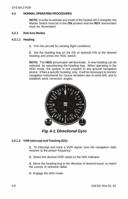
4.2.1.1 Heading
1. Trim the aircraft for existing flight conditions.
2. Set the heading bug on the DG or optional HSI to the desiredheading and press the HDG switch.
NOTE: The HDG annunciator will illuminate. A new heading can beselected by repositioning the heading bug. When operating in theHDG mode, the system is not coupled to any ground navigationdevice. It flies a specific heading, only. It will be necessary to monitornavigation instruments for course deviation due to wind drift, and toestablish wind correction angles.
Fig. 4-1. Directional Gyro
4.2.1.2 VOR Intercept and Tracking (DG)
1. To intercept and track a VOR signal, tune the navigation radioreceiver to the proper frequency.
2. Select the desired VOR radial on the NAV indicator.
3. Move the heading bug in the direction of desired travel, to matchthe course of selected radial.
4. Engage the NAV mode.
PUSH H DG
2nd Ed: Nov 01, 01 4-7
SYS 60-2 POH
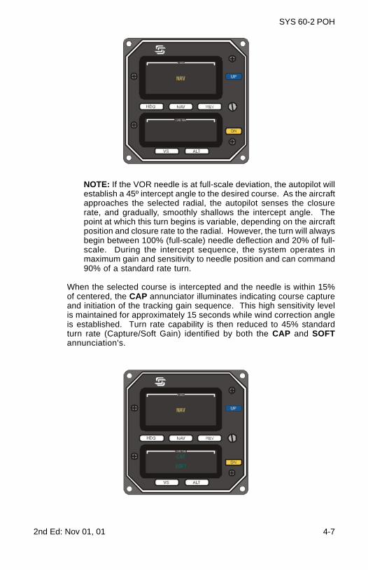
NOTE: If the VOR needle is at full-scale deviation, the autopilot willestablish a 45º intercept angle to the desired course. As the aircraftapproaches the selected radial, the autopilot senses the closurerate, and gradually, smoothly shallows the intercept angle. Thepoint at which this turn begins is variable, depending on the aircraftposition and closure rate to the radial. However, the turn will alwaysbegin between 100% (full-scale) needle deflection and 20% of full-scale. During the intercept sequence, the system operates inmaximum gain and sensitivity to needle position and can command90% of a standard rate turn.
When the selected course is intercepted and the needle is within 15%of centered, the CAP annunciator illuminates indicating course captureand initiation of the tracking gain sequence. This high sensitivity levelis maintained for approximately 15 seconds while wind correction angleis established. Turn rate capability is then reduced to 45% standardturn rate (Capture/Soft Gain) identified by both the CAP and SOFTannunciation's.
4-8 2nd Ed: Nov 01, 01
SYS 60-2 POH
Approximately 45 seconds later, the maximum turn rate is reduced to15% of standard rate (Soft Gain), and the lowest level of sensitivity isachieved, identified by the NAV and SOFT annunciation's. The CAPannunciation extinguishes. This condition provides low activity levelsduring station passage when VOR signals are erratic.
The system also includes a course deviation monitor. If the aircraftstrays off course or LOC centerline by 50% needle deflection, the NAVannunciator flashes as a warning. It should flash at station passagebecause of short-term needle excursion beyond 50%. It also flasheswhen the NAV flag is in view. When that occurs, the FAIL annunciation willilluminate.
NOTE: When operating in the NAV/ SOFT mode, and needle deflectionof 50% or more is experienced for 1½ minutes, the gain programwill switch to NAV/CAP/SOFT, increasing sensitivity and authority toreestablish the aircraft on course. When a course change of 10º ormore is required at an enroute waypoint, select the new course, andreset the NAV mode to reinstate the capture sequence. Set the DGheading bug to the new course.
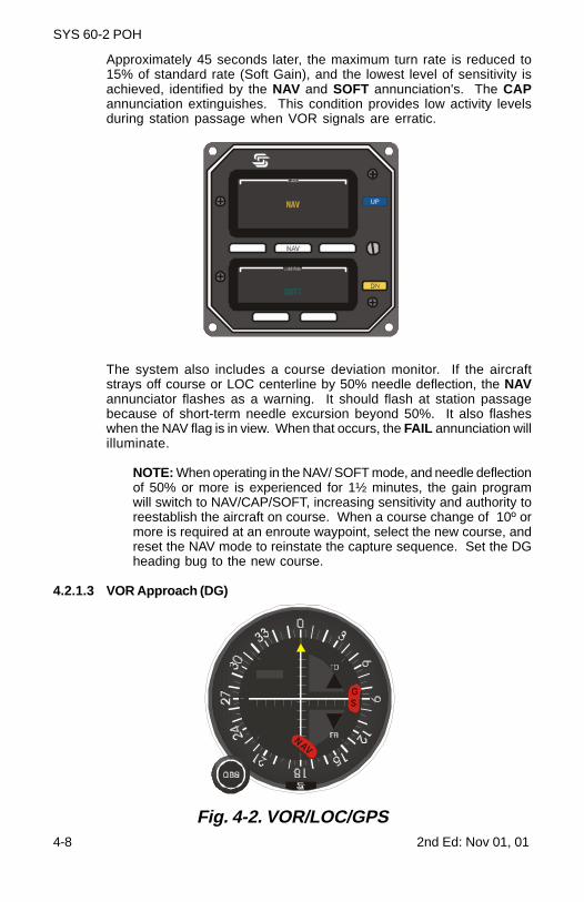
4.2.1.3 VOR Approach (DG)
SNAV
GS
Fig. 4-2. VOR/LOC/GPS
2nd Ed: Nov 01, 01 4-9
SYS 60-2 POH
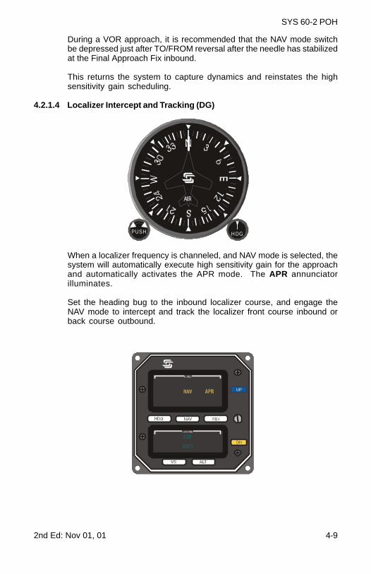
During a VOR approach, it is recommended that the NAV mode switchbe depressed just after TO/FROM reversal after the needle has stabilizedat the Final Approach Fix inbound.
This returns the system to capture dynamics and reinstates the highsensitivity gain scheduling.
4.2.1.4 Localizer Intercept and Tracking (DG)
When a localizer frequency is channeled, and NAV mode is selected, thesystem will automatically execute high sensitivity gain for the approachand automatically activates the APR mode. The APR annunciatorilluminates.
Set the heading bug to the inbound localizer course, and engage theNAV mode to intercept and track the localizer front course inbound orback course outbound.
PUSH H DG
4-10 2nd E
d: Nov 01, 01
SY
S 60-2 P
OH
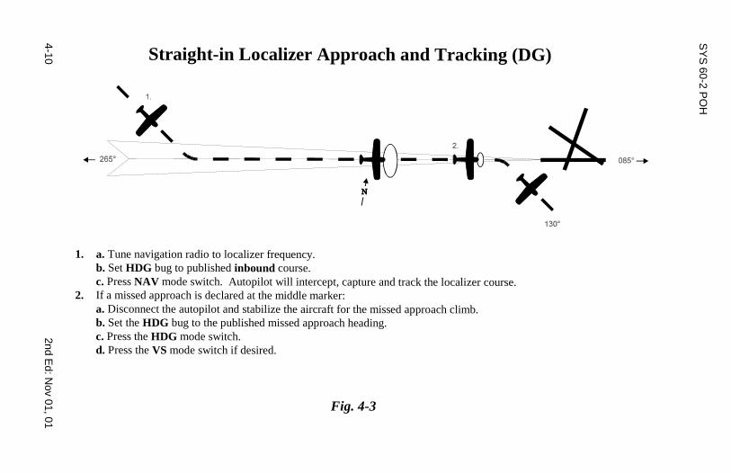
Straight-in Localizer Approach and Tracking (DG)
1. a. Tune navigation radio to localizer frequency.b. Set HDG bug to published inbound course.c. Press NAV mode switch. Autopilot will intercept, capture and track the localizer course.
2. If a missed approach is declared at the middle marker:a. Disconnect the autopilot and stabilize the aircraft for the missed approach climb.b. Set the HDG bug to the published missed approach heading.c. Press the HDG mode switch.d. Press the VS mode switch if desired.
Fig. 4-3
2nd Ed: N
ov 01, 014-11
SY
S 60-2 P
OH
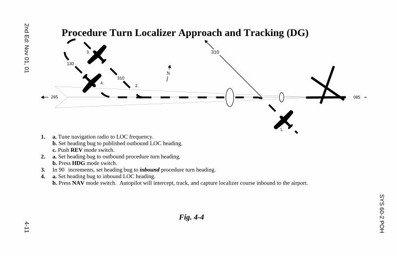
Procedure Turn Localizer Approach and Tracking (DG)
1.
265
N
085
2.
3.
4.
310
310
130
1. a. Tune navigation radio to LOC frequency.b. Set heading bug to published outbound LOC heading.c. Push REV mode switch.
2. a. Set heading bug to outbound procedure turn heading.b. Press HDG mode switch.
3. In 90 increments, set heading bug to inbound procedure turn heading.4. a. Set heading bug to inbound LOC heading.
b. Press NAV mode switch. Autopilot will intercept, track, and capture localizer course inbound to the airport.
Fig. 4-4
4-12 2nd E
d: Nov 01, 01
SY
S 60-2 P
OH
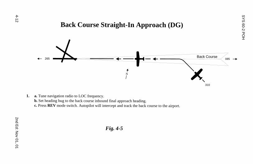
Back Course Straight-In Approach (DG)
1. a. Tune navigation radio to LOC frequency.b. Set heading bug to the back course inbound final approach heading.c. Press REV mode switch. Autopilot will intercept and track the back course to the airport.
Fig. 4-5
265 085Back Course
310
N
2nd Ed: N
ov 01, 014-13
SY
S 60-2 P
OH
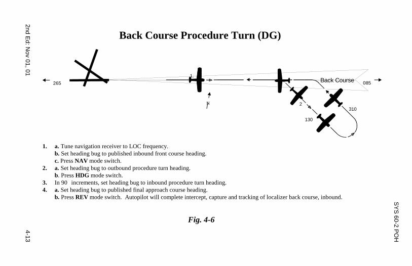
Back Course Procedure Turn (DG)
1. a. Tune navigation receiver to LOC frequency.b. Set heading bug to published inbound front course heading.c. Press NAV mode switch.
2. a. Set heading bug to outbound procedure turn heading.b. Press HDG mode switch.
3. In 90 increments, set heading bug to inbound procedure turn heading.4. a. Set heading bug to published final approach course heading.
b. Press REV mode switch. Autopilot will complete intercept, capture and tracking of localizer back course, inbound.
Fig. 4-6
265
N
085
310
130
1.
2
Back Course
4-14 2nd Ed: Nov 01, 01
SYS 60-2 POH
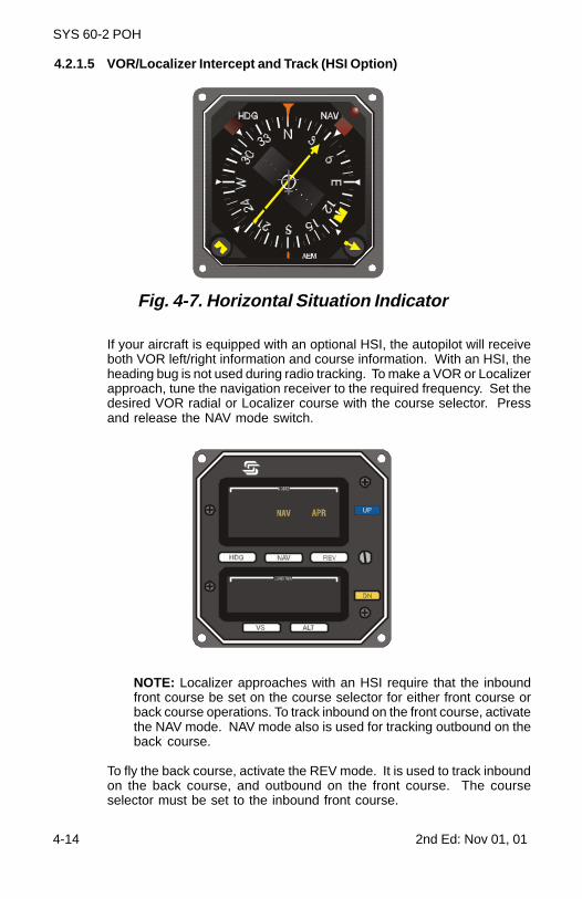
4.2.1.5 VOR/Localizer Intercept and Track (HSI Option)
Fig. 4-7. Horizontal Situation Indicator
If your aircraft is equipped with an optional HSI, the autopilot will receiveboth VOR left/right information and course information. With an HSI, theheading bug is not used during radio tracking. To make a VOR or Localizerapproach, tune the navigation receiver to the required frequency. Set thedesired VOR radial or Localizer course with the course selector. Pressand release the NAV mode switch.
NOTE: Localizer approaches with an HSI require that the inboundfront course be set on the course selector for either front course orback course operations. To track inbound on the front course, activatethe NAV mode. NAV mode also is used for tracking outbound on theback course.
To fly the back course, activate the REV mode. It is used to track inboundon the back course, and outbound on the front course. The courseselector must be set to the inbound front course.
2nd Ed: Nov 01, 01 4-15
SYS 60-2 POH
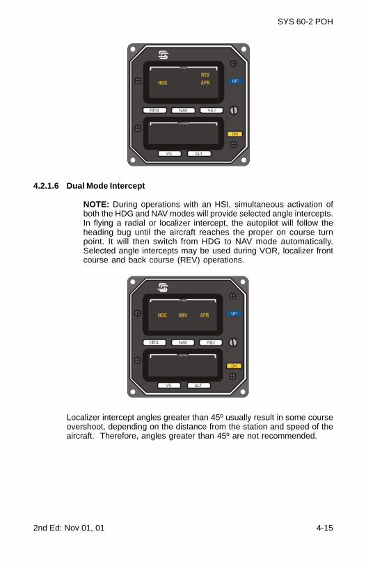
4.2.1.6 Dual Mode Intercept
NOTE: During operations with an HSI, simultaneous activation ofboth the HDG and NAV modes will provide selected angle intercepts.In flying a radial or localizer intercept, the autopilot will follow theheading bug until the aircraft reaches the proper on course turnpoint. It will then switch from HDG to NAV mode automatically.Selected angle intercepts may be used during VOR, localizer frontcourse and back course (REV) operations.
Localizer intercept angles greater than 45º usually result in some courseovershoot, depending on the distance from the station and speed of theaircraft. Therefore, angles greater than 45º are not recommended.
4-16 2nd E
d: Nov 01, 01
SY
S 60-2 P
OH
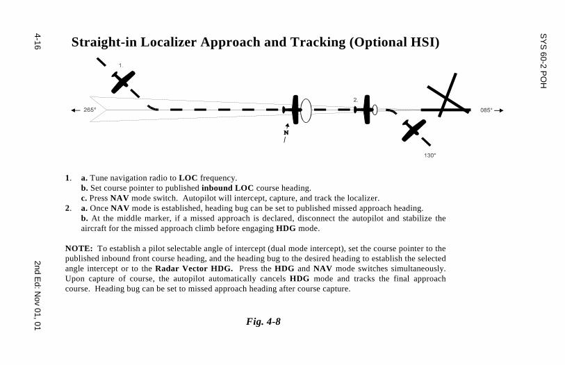
Straight-in Localizer Approach and Tracking (Optional HSI)
1. a. Tune navigation radio to LOC frequency.b. Set course pointer to published inbound LOC course heading.c. Press NAV mode switch. Autopilot will intercept, capture, and track the localizer.
2. a. Once NAV mode is established, heading bug can be set to published missed approach heading.b. At the middle marker, if a missed approach is declared, disconnect the autopilot and stabilize theaircraft for the missed approach climb before engaging HDG mode.
NOTE: To establish a pilot selectable angle of intercept (dual mode intercept), set the course pointer to thepublished inbound front course heading, and the heading bug to the desired heading to establish the selectedangle intercept or to the Radar Vector HDG. Press the HDG and NAV mode switches simultaneously.Upon capture of course, the autopilot automatically cancels HDG mode and tracks the final approachcourse. Heading bug can be set to missed approach heading after course capture.
Fig. 4-8
2nd Ed: N
ov 01, 014-17
SY
S 60-2 P
OH
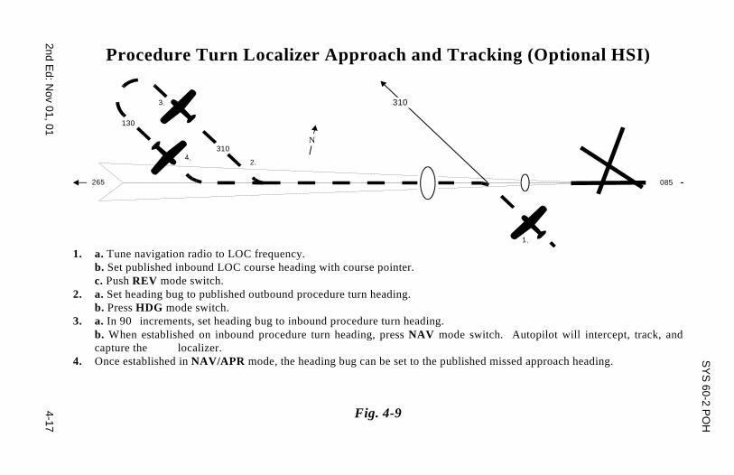
Procedure Turn Localizer Approach and Tracking (Optional HSI)
1.
265
N
085
2.
3.
4.
310
310
130
1. a. Tune navigation radio to LOC frequency.b. Set published inbound LOC course heading with course pointer.c. Push REV mode switch.
2. a. Set heading bug to published outbound procedure turn heading.b. Press HDG mode switch.
3. a. In 90 increments, set heading bug to inbound procedure turn heading.b. When established on inbound procedure turn heading, press NAV mode switch. Autopilot will intercept, track, andcapture the localizer.
4. Once established in NAV/APR mode, the heading bug can be set to the published missed approach heading.
Fig. 4-9
4-18 2nd E
d: Nov 01, 01
SY
S 60-2 P
OH
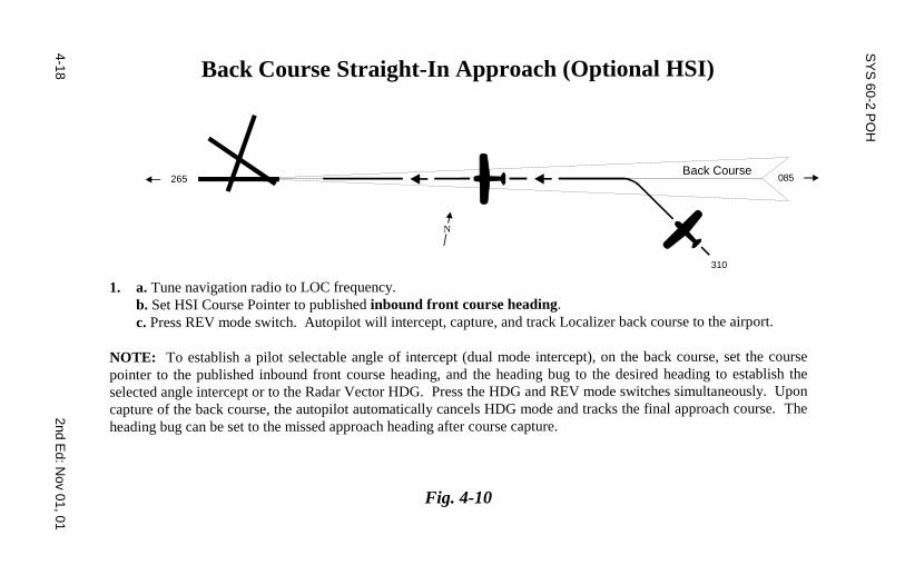
Back Course Straight-In Approach (Optional HSI)
1. a. Tune navigation radio to LOC frequency.b. Set HSI Course Pointer to published inbound front course heading.c. Press REV mode switch. Autopilot will intercept, capture, and track Localizer back course to the airport.
NOTE: To establish a pilot selectable angle of intercept (dual mode intercept), on the back course, set the coursepointer to the published inbound front course heading, and the heading bug to the desired heading to establish theselected angle intercept or to the Radar Vector HDG. Press the HDG and REV mode switches simultaneously. Uponcapture of the back course, the autopilot automatically cancels HDG mode and tracks the final approach course. Theheading bug can be set to the missed approach heading after course capture.
Fig. 4-10
265 085Back Course
310
N
2nd Ed: N
ov 01, 014-19
SY
S 60-2 P
OH
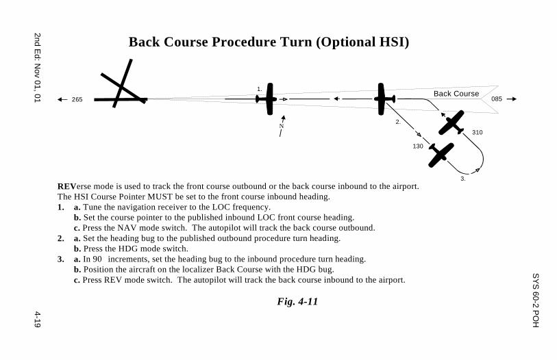
Back Course Procedure Turn (Optional HSI)
REVerse mode is used to track the front course outbound or the back course inbound to the airport.The HSI Course Pointer MUST be set to the front course inbound heading.1. a. Tune the navigation receiver to the LOC frequency.
b. Set the course pointer to the published inbound LOC front course heading.c. Press the NAV mode switch. The autopilot will track the back course outbound.
2. a. Set the heading bug to the published outbound procedure turn heading.b. Press the HDG mode switch.
3. a. In 90 increments, set the heading bug to the inbound procedure turn heading.b. Position the aircraft on the localizer Back Course with the HDG bug.c. Press REV mode switch. The autopilot will track the back course inbound to the airport.
Fig. 4-11
265
N
085
310
130
1.
2.
3.
Back Course
4-20 2nd Ed: Nov 01, 01
SYS 60-2 POH
4.2.2 Pitch Axis Modes
NOTE: A Roll Mode must be selected before selecting a Pitch Mode.
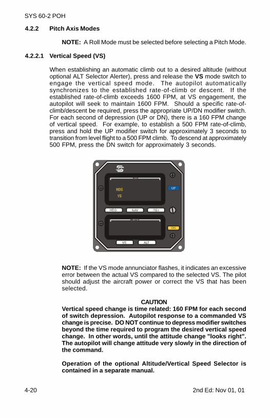
4.2.2.1 Vertical Speed (VS)
When establishing an automatic climb out to a desired altitude (withoutoptional ALT Selector Alerter), press and release the VS mode switch toengage the vertical speed mode. The autopilot automaticallysynchronizes to the established rate-of-climb or descent. If theestablished rate-of-climb exceeds 1600 FPM, at VS engagement, theautopilot will seek to maintain 1600 FPM. Should a specific rate-of-climb/descent be required, press the appropriate UP/DN modifier switch.For each second of depression (UP or DN), there is a 160 FPM changeof vertical speed. For example, to establish a 500 FPM rate-of-climb,press and hold the UP modifier switch for approximately 3 seconds totransition from level flight to a 500 FPM climb. To descend at approximately500 FPM, press the DN switch for approximately 3 seconds.
NOTE: If the VS mode annunciator flashes, it indicates an excessiveerror between the actual VS compared to the selected VS. The pilotshould adjust the aircraft power or correct the VS that has beenselected.
CAUTIONVertical speed change is time related: 160 FPM for each secondof switch depression. Autopilot response to a commanded VSchange is precise. DO NOT continue to depress modifier switchesbeyond the time required to program the desired vertical speedchange. In other words, until the attitude change "looks right".The autopilot will change attitude very slowly in the direction ofthe command.
Operation of the optional Altitude/Vertical Speed Selector iscontained in a separate manual.
2nd Ed: Nov 01, 01 4-21
SYS 60-2 POH
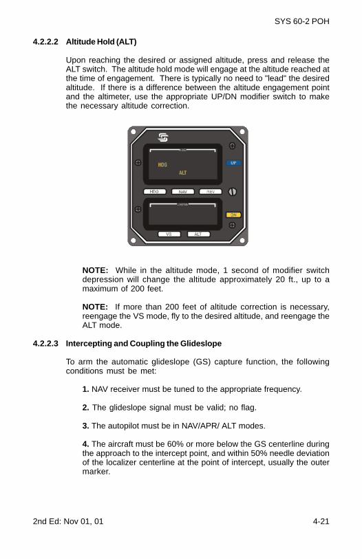
4.2.2.2 Altitude Hold (ALT)
Upon reaching the desired or assigned altitude, press and release theALT switch. The altitude hold mode will engage at the altitude reached atthe time of engagement. There is typically no need to "lead" the desiredaltitude. If there is a difference between the altitude engagement pointand the altimeter, use the appropriate UP/DN modifier switch to makethe necessary altitude correction.
NOTE: While in the altitude mode, 1 second of modifier switchdepression will change the altitude approximately 20 ft., up to amaximum of 200 feet.
NOTE: If more than 200 feet of altitude correction is necessary,reengage the VS mode, fly to the desired altitude, and reengage theALT mode.
4.2.2.3 Intercepting and Coupling the Glideslope
To arm the automatic glideslope (GS) capture function, the followingconditions must be met:
1. NAV receiver must be tuned to the appropriate frequency.
2. The glideslope signal must be valid; no flag.
3. The autopilot must be in NAV/APR/ ALT modes.
4. The aircraft must be 60% or more below the GS centerline duringthe approach to the intercept point, and within 50% needle deviationof the localizer centerline at the point of intercept, usually the outermarker.
4-22 2nd Ed: Nov 01, 01
SYS 60-2 POH
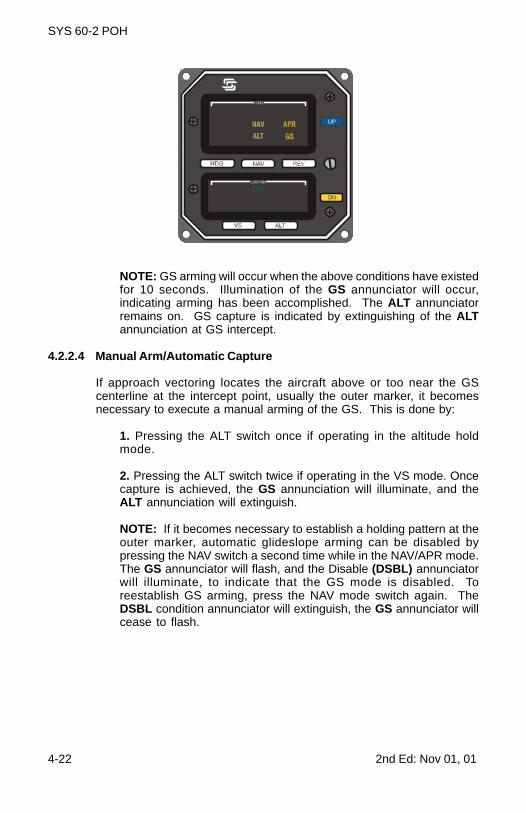
NOTE: GS arming will occur when the above conditions have existedfor 10 seconds. Illumination of the GS annunciator will occur,indicating arming has been accomplished. The ALT annunciatorremains on. GS capture is indicated by extinguishing of the ALTannunciation at GS intercept.
4.2.2.4 Manual Arm/Automatic Capture
If approach vectoring locates the aircraft above or too near the GScenterline at the intercept point, usually the outer marker, it becomesnecessary to execute a manual arming of the GS. This is done by:
1. Pressing the ALT switch once if operating in the altitude holdmode.
2. Pressing the ALT switch twice if operating in the VS mode. Oncecapture is achieved, the GS annunciation will illuminate, and theALT annunciation will extinguish.
NOTE: If it becomes necessary to establish a holding pattern at theouter marker, automatic glideslope arming can be disabled bypressing the NAV switch a second time while in the NAV/APR mode.The GS annunciator will flash, and the Disable (DSBL) annunciatorwill illuminate, to indicate that the GS mode is disabled. Toreestablish GS arming, press the NAV mode switch again. TheDSBL condition annunciator will extinguish, the GS annunciator willcease to flash.
2nd Ed: N
ov 01, 014-23
SY
S 60-2 P
OH
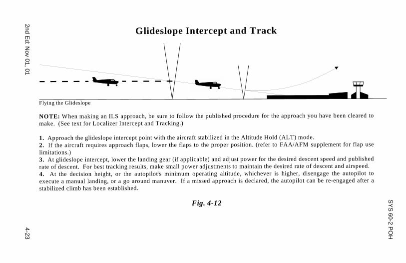
Glideslope Intercept and Track
Flying the Glideslope
NOTE: When making an ILS approach, be sure to follow the published procedure for the approach you have been cleared tomake. (See text for Localizer Intercept and Tracking.)
1. Approach the glideslope intercept point with the aircraft stabilized in the Altitude Hold (ALT) mode.2. If the aircraft requires approach flaps, lower the flaps to the proper position. (refer to FAA/AFM supplement for flap uselimitations.)3. At glideslope intercept, lower the landing gear (if applicable) and adjust power for the desired descent speed and publishedrate of descent. For best tracking results, make small power adjustments to maintain the desired rate of descent and airspeed.4. At the decision height, or the autopilot’s minimum operating altitude, whichever is higher, disengage the autopilot toexecute a manual landing, or a go around manuver. If a missed approach is declared, the autopilot can be re-engaged after astabilized climb has been established.
Fig. 4-12
4-24 2nd E
d: Nov 01, 01
SY
S 60-2 P
OH
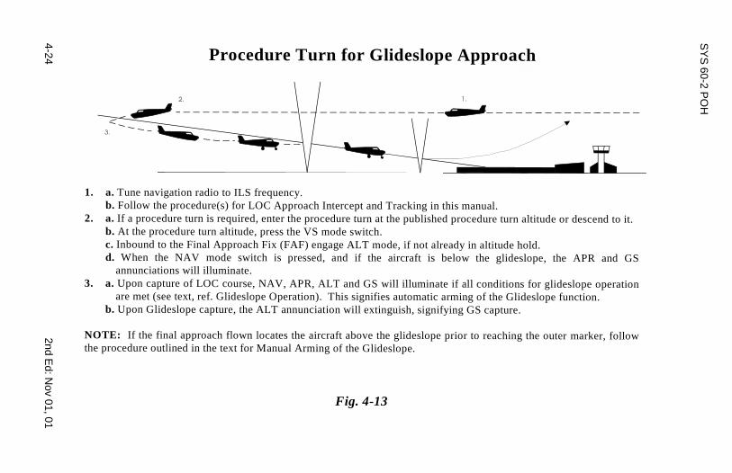
Procedure Turn for Glideslope Approach
1. a. Tune navigation radio to ILS frequency.b. Follow the procedure(s) for LOC Approach Intercept and Tracking in this manual.
2. a. If a procedure turn is required, enter the procedure turn at the published procedure turn altitude or descend to it.b. At the procedure turn altitude, press the VS mode switch.c. Inbound to the Final Approach Fix (FAF) engage ALT mode, if not already in altitude hold.d. When the NAV mode switch is pressed, and if the aircraft is below the glideslope, the APR and GS
annunciations will illuminate.3. a. Upon capture of LOC course, NAV, APR, ALT and GS will illuminate if all conditions for glideslope operation
are met (see text, ref. Glideslope Operation). This signifies automatic arming of the Glideslope function.b. Upon Glideslope capture, the ALT annunciation will extinguish, signifying GS capture.
NOTE: If the final approach flown locates the aircraft above the glideslope prior to reaching the outer marker, followthe procedure outlined in the text for Manual Arming of the Glideslope.
Fig. 4-13
2nd Ed: Nov 01, 01 4-25
SYS 60-2 POH
NOTE: To fly a holding pattern, if inbound to the outer marker while inNAV mode, press the NAV switch a second time to disable the GSarming. When the outer marker is reached, press and release theHDG switch, and rotate the heading bug in the direction of the turn.It is best to select the reciprocal course in increments of 90º, ratherthan the full 180º. When the outbound leg is completed, rotate theHDG bug in the direction of the turn, in 90º increments, to reestablishthe inbound course, and press and release the NAV switch twice.On the inbound leg, when ready to complete the approach, rearmthe GS function by pressing and releasing the NAV switch onceagain. Rearming will occur when all other required functions havebeen met.
4.2.2.5 Elevator Trim Indicator
The autopilot pitch servo contains a sensor for detection of elevator out-of-trim loads. Without optional Autotrim, when such forces exceed apreset level, the TRIM annunciator will illuminate, and either the UP or DNannunciator will light up, indicating the direction of required trim.Annunciation will be steady for about 5 seconds, then will flash untilproper trim conditions have been met.
NOTE: If the TRIM annunciation is illuminated and the autopilot isdisengaged, there will be a residual out-of-trim force at the controlwheel. Be alert for this condition if the autopilot is disengaged whilethe TRIM lights are on.

4-26 2nd Ed: Nov 01, 01
SYS 60-2 POH
4.2.2.6 Optional Autotrim
If the autopilot is equipped with optional Autotrim, the aircraft elevatortrim will be maintained automatically when the Trim Master Switch is ONand a pitch mode is activated.
When the Trim Master Switch is ON, the trim annunciators are disabled.If the switch is OFF, or a power failure occurs, the annunciatorsautomatically become functional.
The trim system is designed to accept any type of single failure,mechanical or electrical, without uncontrolled operation resulting. Toensure that no hidden failures have occurred, conduct a trim preflightcheck prior to every flight. (Consult the appropriate AFMS or POH.)
4.3 Flight Director Operations (Optional)
4.3.1 Single Cue
This system, which integrates both the roll axis, and pitch axis, offerssynchronized display of the flight profile. It is automatically activatedwhen the autopilot pitch axis is engaged. A Flight Director provides avisual indication of how accurately the pilot or autopilot is tracking thecommands of the active mode of operation.
Activation is indicated by illumination of the FD annunciator. A remoteparallax adjustment is provided to change the height of the horizontaldisplay to compensate for different seat heights. And a remote switchallows manual flight control via Flight Director commands.
For proper flight technique, the system presentation requires the pilot toroll and pitch the aircraft toward the display until the delta shapedreference is tucked into the steering command bars, indicating thatcommands have been satisfied. For example, if the display is up andleft, the pilot would be required to establish a left turn, pitch up attitude.As bank angle and vertical speed approach the required amounts, bankangle and pitch up attitude are shallowed. When the delta reference andthe steering bars are matched, the commands have been met. Thereafter,it is necessary to maneuver the aircraft to keep the display elementsmatched in order to accurately fly the selected modes.
Accurate flight director operation requires alertness by the pilot andmonitoring the movement of the display. Keeping it matched is quitesimple. However, control inputs must be timely and smooth for accurateflight director following of the desired command.
For manually controlled flight by the flight director, place the FD masterswitch in the ON position, and the autopilot master switch in the OFFposition. This disables the autopilot servos, allowing the pilot to controlthe aircraft to flight director commands. To return to autopilot flight simplymove the AP switch to "ON".
2nd Ed: Nov 01, 01 4-27
SYS 60-2 POH
4.3.2 Two Cue
This system, also known as an Attitude Director Indicator (ADI), isautomatically activated when the autopilot is engaged. Activation isindicated by illumination of the FD annunciator.
This system contains a vertical steering bar for roll commands, and ahorizontal steering bar for pitch commands. It also includes an FD flagwhich is displayed when the roll steering bar is not active. This systemallows split axis operation so flight in roll axis by itself is available. Thehorizontal pitch steering bar is biased out of view when the AP MasterSwitch is on, until a pitch mode is activated. A remote parallax adjustmentis provided to change the height of the pitch steering bar for differentseat heights. A remote switch allows manual flight control via FlightDirector commands.
Proper flight director technique for a Two Cue steering presentationrequires the pilot to roll and pitch the aircraft toward the steering barsuntil they are centered, indicating that commands have been met.
For example, if the vertical (roll) bar is left, and the horizontal (pitch) baris up, the aircraft is below the desired attitude, or horizon, and right ofdesired course, or centerline. A left bank and a pitch up attitude is dictated.As bank angle and vertical speed approach desired values, the bars willmove to the center, or "crossed-hair" position. At this point, commandshave been satisfied. Thereafter, it is necessary only to maneuver theaircraft to keep the bars centered in order to accurately fly programmedmodes.
It should be noted that accurate Flight Director operation demands thatthe pilot stay alert to the movement of the steering bars, and to maneu-ver the aircraft in a timely and smooth manner to satisfy the bar com-mands.
Proper use of a Flight Director System makes flying much more preciseand less burdensome because of the computed display.
4.4 Yaw Damper/Rudder Trim System (Optional)
The S-TEC accelerometer controlled yaw damper/rudder trim systemsubstantially improves autopilot performance, as it senses both yawand slip in a single sensor. It also contains a trim potentiometer thatallows centering of the turn and slip ball. It replaces the commonly usedrate gyro with a sensitive accelerometer. The S-TEC system offers twomodes of operation:
1. Auto, which automatically activates when the autopilot isengaged.2. ON, which permits operation whether or not the autopilot isin use.
It also provides a three position switch, which lets the pilot select AUTO,ON, or Off positions.

4-28 2nd Ed: Nov 01, 01
SYS 60-2 POH
Page Intentionally Blank

2nd Ed: Nov 01, 01 5-1
SYS 60-2 POH
SECTION 5APPENDIXES

5-2 2nd Ed: Nov 01, 01
SYS 60-2 POH
Table of Contents
Appendix A: System Failure and Caution Annunciations.....5-3
Roll Axis..........................................5-3
Pitch Axis........................................5-4
Appendix B: Specifications...............................................5-5
2nd Ed: Nov 01, 01 5-3
SYS 60-2 POH
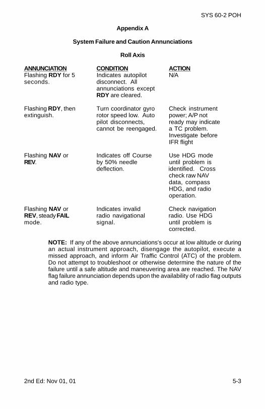
Appendix A
System Failure and Caution Annunciations
Roll Axis
ANNUNCIATION CONDITION ACTIONFlashing RDY for 5 Indicates autopilot N/Aseconds. disconnect. All
annunciations exceptRDY are cleared.
Flashing RDY, then Turn coordinator gyro Check instrumentextinguish. rotor speed low. Auto power; A/P not
pilot disconnects, ready may indicatecannot be reengaged. a TC problem.
Investigate beforeIFR flight
Flashing NAV or Indicates off Course Use HDG modeREV. by 50% needle until problem is
deflection. identified. Crosscheck raw NAVdata, compassHDG, and radiooperation.
Flashing NAV or Indicates invalid Check navigationREV, steady FAIL radio navigational radio. Use HDGmode. signal. until problem is
corrected.
NOTE: If any of the above annunciations's occur at low altitude or duringan actual instrument approach, disengage the autopilot, execute amissed approach, and inform Air Traffic Control (ATC) of the problem.Do not attempt to troubleshoot or otherwise determine the nature of thefailure until a safe altitude and maneuvering area are reached. The NAVflag failure annunciation depends upon the availability of radio flag outputsand radio type.
5-4 2nd Ed: Nov 01, 01
SYS 60-2 POH
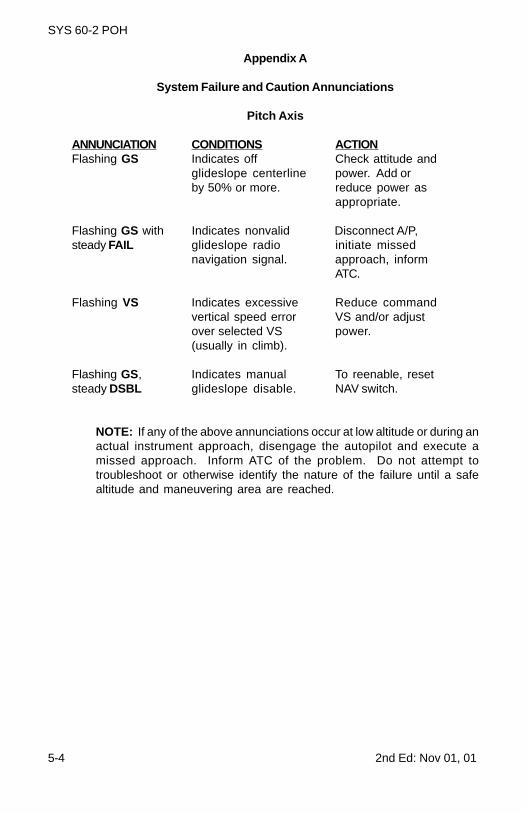
Appendix A
System Failure and Caution Annunciations
Pitch Axis
ANNUNCIATION CONDITIONS ACTIONFlashing GS Indicates off Check attitude and
glideslope centerline power. Add orby 50% or more. reduce power as
appropriate.
Flashing GS with Indicates nonvalid Disconnect A/P,steady FAIL glideslope radio initiate missed
navigation signal. approach, informATC.
Flashing VS Indicates excessive Reduce commandvertical speed error VS and/or adjustover selected VS power.(usually in climb).
Flashing GS, Indicates manual To reenable, resetsteady DSBL glideslope disable. NAV switch.
NOTE: If any of the above annunciations occur at low altitude or during anactual instrument approach, disengage the autopilot and execute amissed approach. Inform ATC of the problem. Do not attempt totroubleshoot or otherwise identify the nature of the failure until a safealtitude and maneuvering area are reached.
2nd Ed: Nov 01, 01 5-5
SYS 60-2 POH
Appendix B
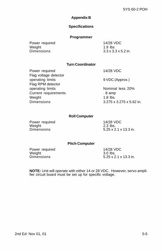
Specifications
Programmer
Power required 14/28 VDCWeight 1.9 lbsDimensions 3.3 x 3.3 x 5.2 in.
Turn Coordinator
Power required 14/28 VDCFlag voltage detectoroperating limits 9 VDC (Approx.)Flag RPM detectoroperating limits Nominal less 20%Current requirements . 8 ampWeight 1.8 lbs.Dimensions 3.275 x 3.275 x 5.62 in.
Roll Computer
Power required 14/28 VDCWeight 2.3 lbs.Dimensions 5.25 x 2.1 x 13.3 in.
Pitch Computer
Power required 14/28 VDCWeight 3.0 lbs.Dimensions 5.25 x 2.1 x 13.3 in.
NOTE: Unit will operate with either 14 or 28 VDC. However, servo ampli-fier circuit board must be set up for specific voltage.
5-6 2nd Ed: Nov 01, 01
SYS 60-2 POH
Appendix B
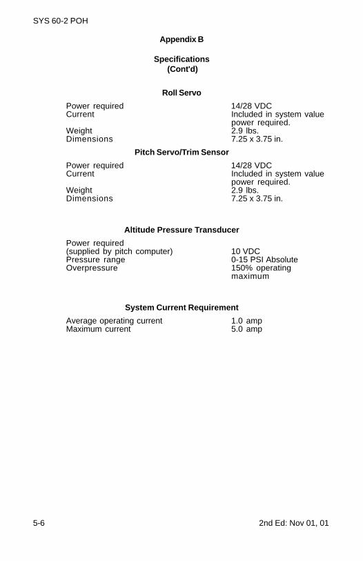
Specifications (Cont'd)
Roll Servo
Power required 14/28 VDCCurrent Included in system value
power required.Weight 2.9 lbs.Dimensions 7.25 x 3.75 in.
Pitch Servo/Trim Sensor
Power required 14/28 VDCCurrent Included in system value
power required.Weight 2.9 lbs.Dimensions 7.25 x 3.75 in.
Altitude Pressure Transducer
Power required(supplied by pitch computer) 10 VDCPressure range 0-15 PSI AbsoluteOverpressure 150% operating
maximum
System Current Requirement
Average operating current 1.0 ampMaximum current 5.0 amp

2nd Ed: Nov 01, 01 6-1
SYS 60-2 POH
SECTION 6GLOSSARY

6-2 2nd Ed: Nov 01, 01
SYS 60-2 POH
Page Intentionally Blank
2nd Ed: Nov 01, 01 6-3
SYS 60-2 POH
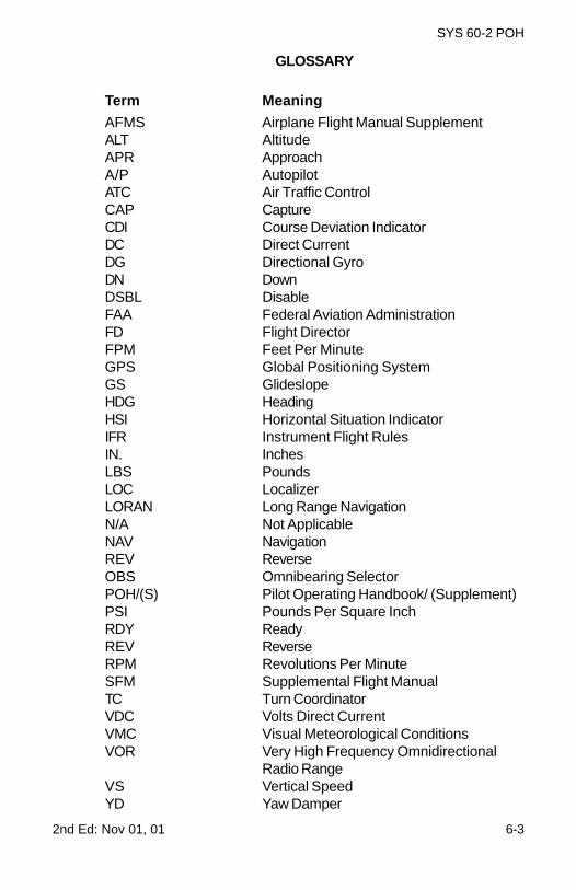
GLOSSARY
Term Meaning
AFMS Airplane Flight Manual SupplementALT AltitudeAPR ApproachA/P AutopilotATC Air Traffic ControlCAP CaptureCDI Course Deviation IndicatorDC Direct CurrentDG Directional GyroDN DownDSBL DisableFAA Federal Aviation AdministrationFD Flight DirectorFPM Feet Per MinuteGPS Global Positioning SystemGS GlideslopeHDG HeadingHSI Horizontal Situation IndicatorIFR Instrument Flight RulesIN. InchesLBS PoundsLOC LocalizerLORAN Long Range NavigationN/A Not ApplicableNAV NavigationREV ReverseOBS Omnibearing SelectorPOH/(S) Pilot Operating Handbook/ (Supplement)PSI Pounds Per Square InchRDY ReadyREV ReverseRPM Revolutions Per MinuteSFM Supplemental Flight ManualTC Turn CoordinatorVDC Volts Direct CurrentVMC Visual Meteorological ConditionsVOR Very High Frequency Omnidirectional
Radio RangeVS Vertical SpeedYD Yaw Damper

6-4 2nd Ed: Nov 01, 01
SYS 60-2 POH
Page Intentionally Blank

S-TEC CorporationA Meggitt Aerospace Systems Company
One S-TEC Way · Municipal AirportMineral Wells, Texas 76067-9236 USA
Telephone 940/325-9406; FAX 940/325-39041-800-USA-STECwww.s-tec.com
Information in this document is subject to change without notice. ©2001S-TEC Corporation. All rights reserved. Printed in the United States of America.S-TEC and the S-TEC logo are registered trademarks of S-TEC Corporation.
P/N: 8783Date: 01 November 20 01Printed in USA