system effects presented by: joe brooks, amca international, inc. amca international technical...
TRANSCRIPT
System Effects
Presented by:
Joe Brooks, AMCA International, Inc.
AMCA International TechnicalSeminar 2009
System Effects, Slide 2
The Air Movement and Control Association International (AMCA), has met the standards and requirements of the Registered Continuing Education Providers Program. Credit earned on completion of this program will be reported to the RCEPP. A certificate of completion will be issued to each participant. As such, it does not include content that may be deemed or construed to be an approval or endorsement by NCEES or RCEPP.

System Effects, Slide 3
Learning ObjectivesLearning Objectives
Describe system resistance of componentsDescribe system resistance of components
Know how a fan interacts with the systemKnow how a fan interacts with the system
Define System Effect and System Effect Factor Define System Effect and System Effect Factor (SEF)(SEF)
Know how to avoid system effect factorsKnow how to avoid system effect factors
System Effects, Slide 4
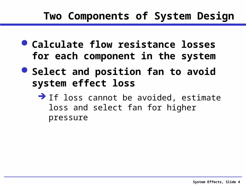
Two Components of System Design
Calculate flow resistance losses for each component in the system
Select and position fan to avoid system effect loss If loss cannot be avoided, estimate loss and
select fan for higher pressure
System Effects, Slide 5
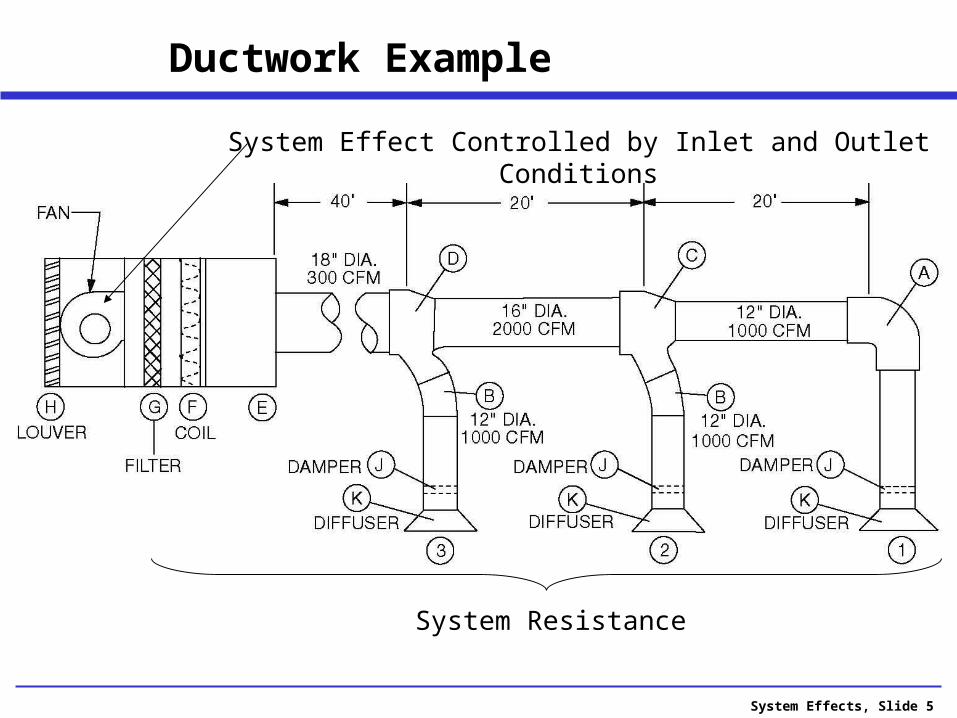
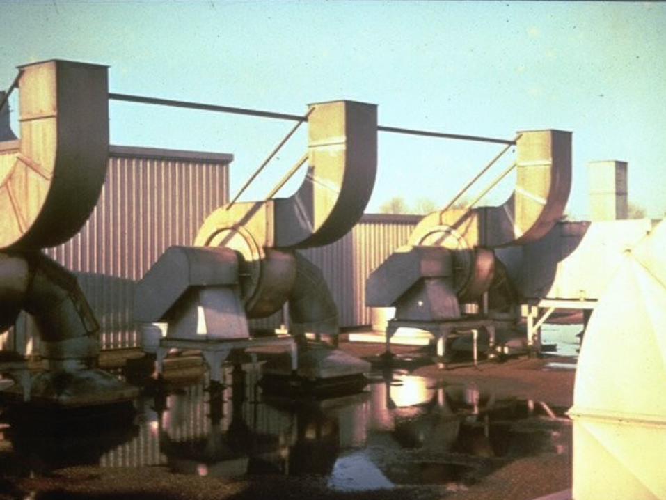
Ductwork Example
System Resistance
System Effect Controlled by Inlet and Outlet Conditions
System Effects, Slide 6
Causes of Non-Performing Systems
System resistance miscalculated.
Fan not properly selected.
Defective fan (or fan rating).
There is a system effect loss.

System Effects, Slide 7
Fan Manufacturer’s Responsibility
Provide accurate fan performance ratings.
Provide a fan built within tolerance so that it is capable of meeting its rating.

System Effects, Slide 8
What is System Effect?
A factor used to correct for system induced installation effects.
The difference in performance between a fan tested in the laboratory and one tested in a real installation.
System Effects, Slide 9
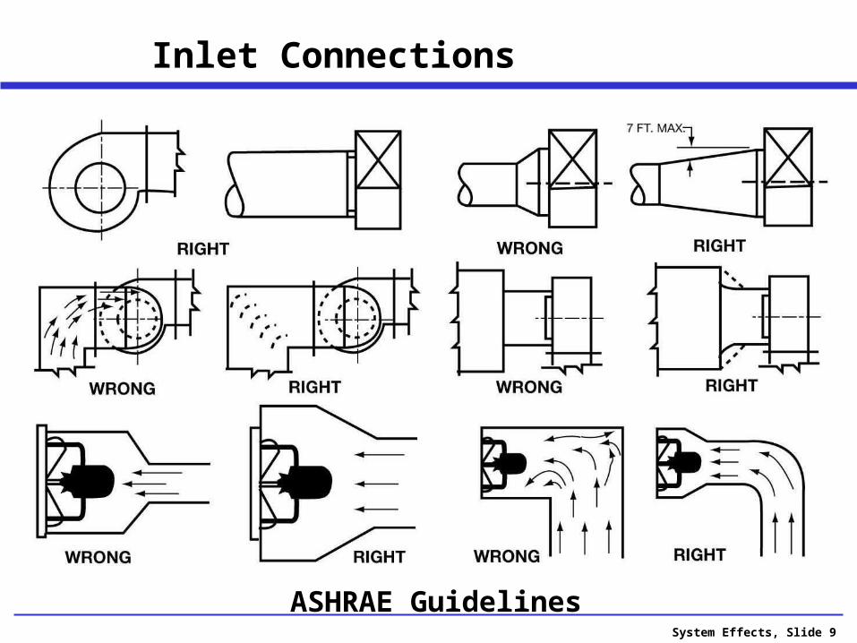
Inlet Connections
ASHRAE Guidelines

System Effects, Slide 10
Outlet Connections
ASHRAE Guidelines

System Effects, Slide 11
Outlet Connections
ASHRAE Guidelines
System Effects, Slide 12
What is Missing?
Only guidelines to avoid losses.
No way to quantify losses.

System Effects, Slide 13
AMCA Publication 201-02
The bible of system effects
Generated from ASHRAE funded research

System Effects, Slide 14
Credibility Gap
Are system effects just fudge factors that the fan manufacturers made up?
System effect video.
System Effects, Slide 15
Definition of System Effect
Fan ratings are established using AMCA 210 test codes that are close to ideal conditions.
Fans in actual systems are often less than ideal.
The difference in performance for the same fan tested in both conditions is the “System Effect”.
System Effects, Slide 16
Purpose of Discussion
Aimed primarily at the fan system designer
There are two goals:
Avoid poor fan system configurations
When optimum conditions cannot be met, use the “system effect” factors to estimate any losses during system design.
System Effects, Slide 17
Why System Effect is Important
May have to accept deficient performance, or... Speed up the fan (if possible) May require more energy to meet performance May exceed motor horsepower limit
Many cause excessive noise
Many cause excessive vibration
System Effects, Slide 18
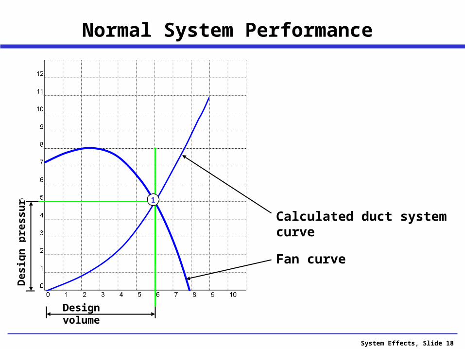
Normal System Performance
Design volume
Fan curve
Calculated duct system curve
Des
ign
pre
ssu
re
1
System Effects, Slide 19
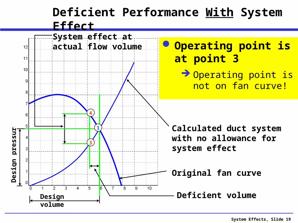
Deficient Performance With System Effect
Design volume
Original fan curve
Deficient volume
3
Calculated duct system with no allowance for system effect
4
System effect at actual flow volume
Des
ign
pre
ssu
re
1
Operating point is at point 3 Operating point is not
on fan curve!
System Effects, Slide 20
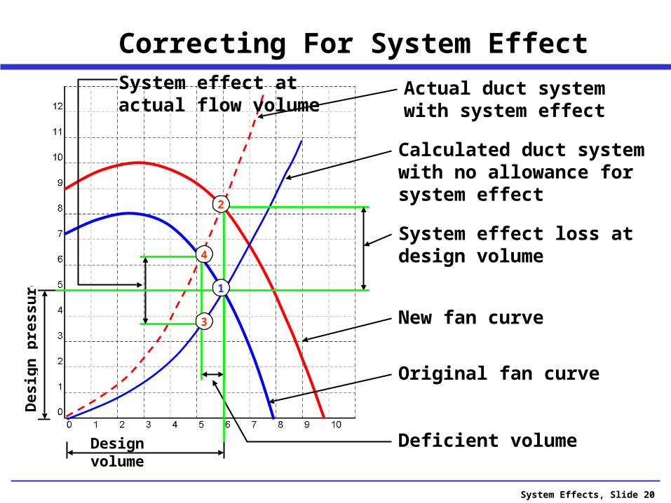
Correcting For System Effect
Design volume
Original fan curve
New fan curve
System effect loss at design volume
2
Deficient volume
3
Calculated duct system with no allowance for system effect
4
System effect at actual flow volume
Actual duct system with system effect
Des
ign
pre
ssu
re
1

System Effects, Slide 21
The fan will be selected for the higher pressure (no need to speed up).
The motor will be selected to include the anticipated loss.
With System Effects Added:
System Effects, Slide 22
What are the Causes of the Losses?
Inlet losses are caused by: Unequal loading of the fan blades (eccentric
flow). Improper fan blade attack angle. Turbulence which disrupts the flow.
Outlet losses are caused by: Loss of conversion of local high velocity into
pressure.
System Effects, Slide 23
Inlet induced losses tend to be higher than outlet losses.
Losses induced on the inlet can often exceed 20%.
Losses as high as 50% have been reported.
Inlet vs. Outlet Losses

System Effects, Slide 24
Straight uniform flow directed only in the axial direction--on the fan inlet
For Ducted fans - a straight length of outlet ductwork
Good Flow Conditions for a Fan:

System Effects, Slide 26
AMCA Publication 210-07
Defines standard methods of testing fans for rating purposes
System Effects, Slide 27
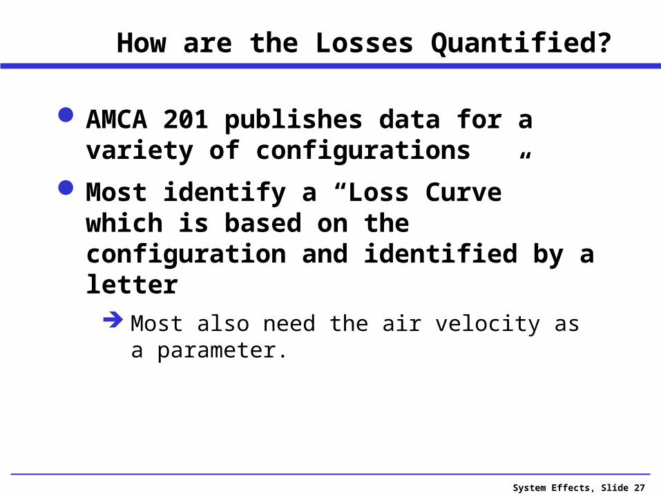
How are the Losses Quantified?
AMCA 201 publishes data for a variety of configurations
Most identify a “Loss Curve” which is based on the configuration and identified by a letter Most also need the air velocity as a parameter.

System Effects, Slide 28
System Effect Curves
4000 FPM
Curve T
Add 0.55 to Static Pressure
System Effects, Slide 29
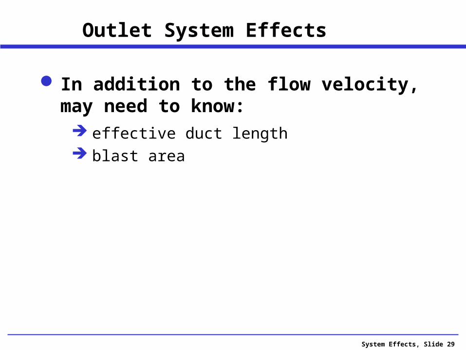
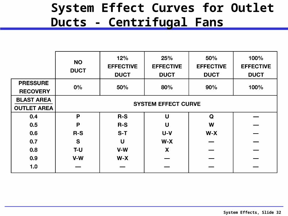
Outlet System Effects
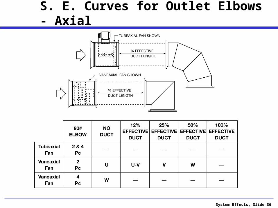
In addition to the flow velocity, may need to know: effective duct length blast area
System Effects, Slide 30
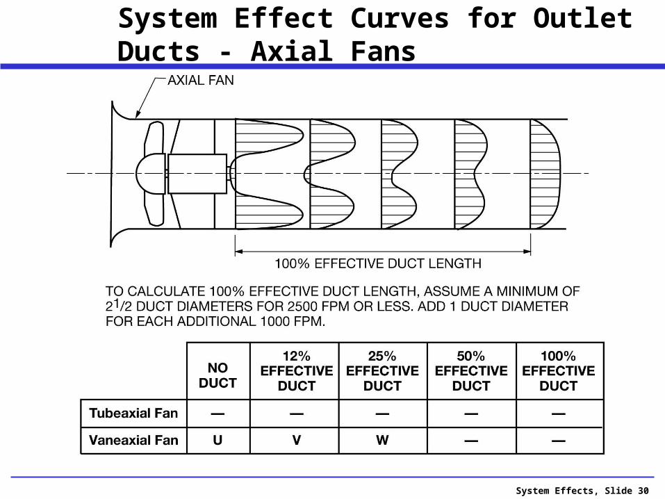
System Effect Curves for Outlet Ducts - Axial Fans
System Effects, Slide 31
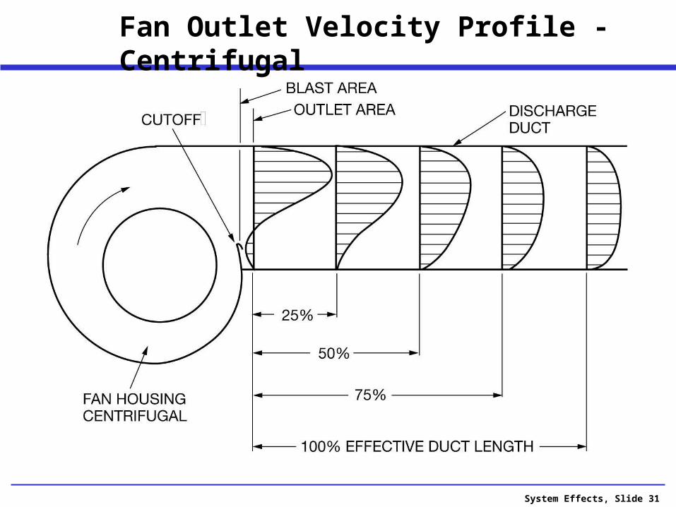
Fan Outlet Velocity Profile - Centrifugal
System Effects, Slide 32
System Effect Curves for Outlet Ducts - Centrifugal Fans
System Effects, Slide 33
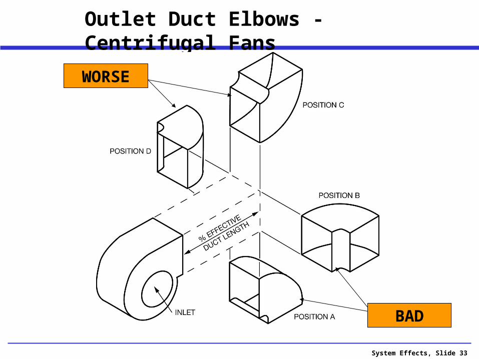
Outlet Duct Elbows - Centrifugal Fans
BAD
WORSE
System Effects, Slide 34
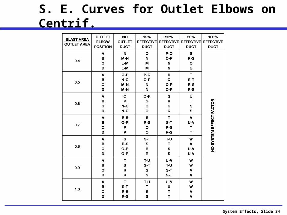
S. E. Curves for Outlet Elbows on Centrif.
System Effects, Slide 35
System Effects, Slide 36
S. E. Curves for Outlet Elbows - Axial

System Effects, Slide 37
S. E. Curves for Inlet Elbows - Axial

System Effects, Slide 38
Percentage of Unobstructed Inlet Area

System Effects, Slide 39
Fans and Plenum – Two Losses
Distance L / (Inlet Dia.) gives one loss
Loss factors given for 0.3 to 0.75 clearance
Note: Spacing for two fans is important
Keep inlet centerline on centerline of unit
No loss factors given

System Effects, Slide 40
Elbows Change the Velocity Profile
Fan inlet here will create a system effect loss for any type of fan
System Effects, Slide 41
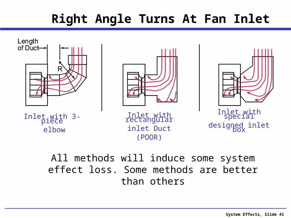
Right Angle Turns At Fan Inlet
Inlet with rectangularinlet Duct(POOR)
Inlet with 3-piece elbow
Inlet with specialdesigned inlet box
All methods will induce some system effect loss. Some methods are better than others

System Effects, Slide 42
System Effect - Round Inlet Ducts
R
Lengthof Duct
R
R
Lengthof Duct
Lengthof Duct
D D D
System Effect Curves
R/D NoDuct
2DDuct
5DDu ct
-- N P R-S
System Effect Curves
R/D NoDuct
2DDuct
5DDuct
0.5 O Q S
0.75 Q R-S T-U
1.0 R S-T U-V
2.0 R-S T U-V
3.0 S T-U V
System Effect Curves
R/D NoDuct
2DDuct
5DDuct
0.5 P-Q R-S T
0.75 Q-R S U
1.0 R S-T U-V
2.0 R-S T U-V
3.0 S-T U V-
2 piece miteredround section
3 piece mitered round section
4 or more piecemitered round section
System Effects, Slide 43
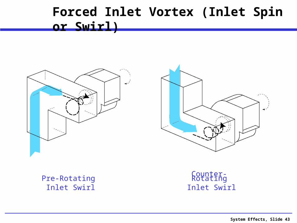
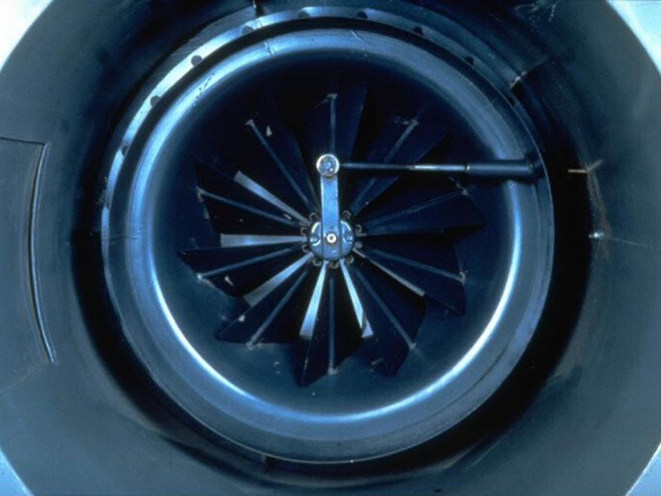
Forced Inlet Vortex (Inlet Spin or Swirl)
Pre-Rotating Inlet Swirl
Counter-Rotating Inlet Swirl
System Effects, Slide 44
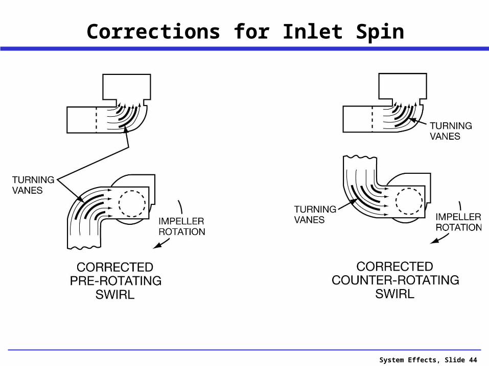
Corrections for Inlet Spin

System Effects, Slide 46
Normalized Pressure-Volume Curve
Note that this is similar to a variable system effect.
A new curve is generated at each vane setting
System Effects, Slide 47
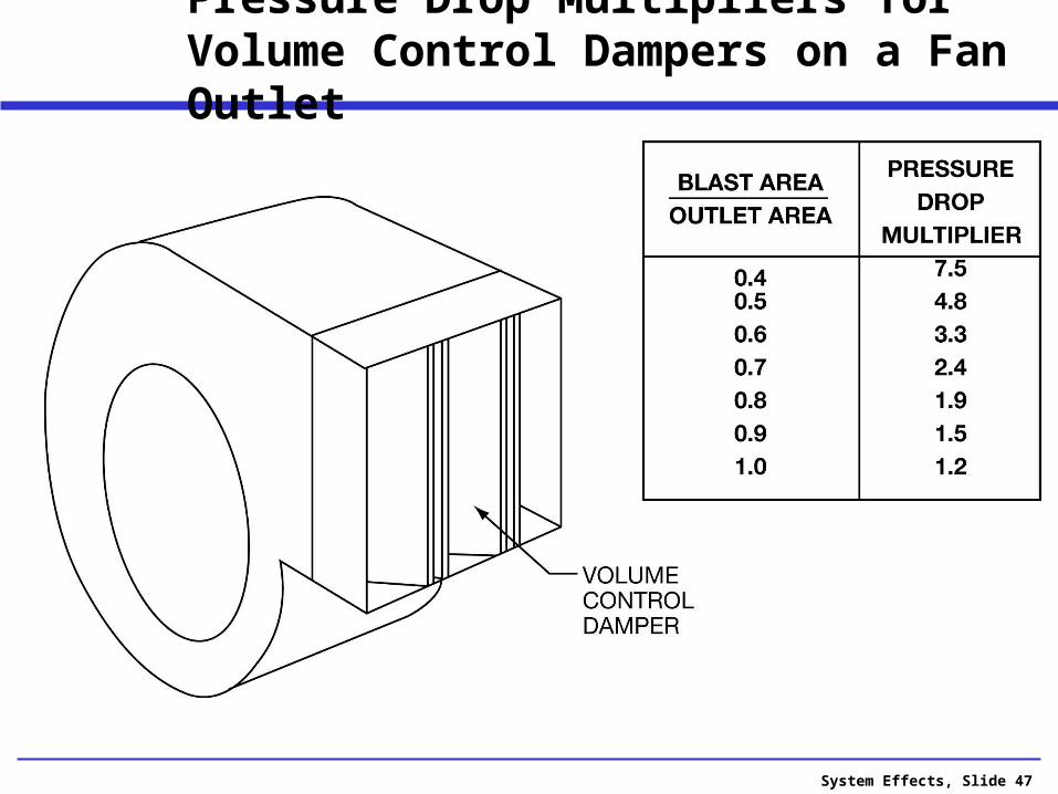
Pressure Drop Multipliers for Volume Control Dampers on a Fan Outlet

System Effects, Slide 48
Measured Inlet Sound Power
70
80
90
100
110
63 125 250 500 1000 2000 4000 8000
Fan Only 2 PC Elbow on Inlet 2 PC Elbow 3 De
Blade Pass - 135 Hz
Vaneaxial Fan System Effect

System Effects, Slide 49
System Effect Factors are Real
When designing your fan/system, do everything possible to avoid a “system effect” for efficient use of energy
When conditions leading to system effect cannot be avoided, add the calculated loss to the fan pressure requirement at the system design stage.
System Effects, Slide 50
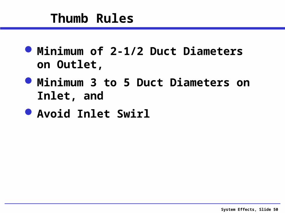
Thumb Rules
Minimum of 2-1/2 Duct Diameters on Outlet,
Minimum 3 to 5 Duct Diameters on Inlet, and
Avoid Inlet Swirl


System Effects, Slide 57

System Effects, Slide 59
Questions?Questions?

System Effects, Slide 60