system (iiss) volume 8 1/1 ul e e em oh e oh oh lh-a182 588 integrated information support system...
TRANSCRIPT

-A182 588 INTEGRATED INFORMATION SUPPORT SYSTEM (IISS) VOLUME 8 1/1USER INTERFACE SUBS (U) GENERAL ELECTRIC COSCHENECTADY NY PRODUCTION RESOURCES CONSU
UL lBUTTERORTH ET AL i NOY 85 OS-626i445i F/6 12/5 U
E E Em oh E oh E oh lh E

S5S5%,*11.
-[25 1.A .
Ml P .,-OPY RESOLUTION ILhS CHARI
./'e
NZ

AD-A 182 588
AFWAL-TR-86-4006
Volume VIIIPart 20
INTEGRATED INFORMATIONSUPPORT SYSTEM (IISS)Volume VIII - User Interface SubsystemPart 20 - Report Writer Development Specification
General Electric CompanyProduction Resources ConsultingOne River RoadSchenectady. New York 12345
Final Report for Period 22 September 1980 - 31 July 1985
November 1985
Approved for public release; distribution is unlimited.
T1T
MATERIALS LABORATORY JUL 1 6 IG87AIR FORCE WRIGHT AERONAUTICAL LABORATORIESAIR FORCE SYSTEMS COMMANDWRIGHT-PATTERSON AFB, OH 45433-6533 E
87 ' /5 o34

NOTICE
When Government drawings specifications, or other data are used for any purpose other thanin connection with a definitely related Government procurement operation, the United StatesGovernment thereby incurs no responsibility nor any obligation whatsoever, and the fact that thegovernment may have formulated furnished or in any way supplied the said drawings.specifications or Other data, is not to be regarded by implication or otherwise as in anymanner licensing the holoer or any other person or corporation, or conveying any rights orpermission to manufacture use. or sell any patented invention that may in any way be relatedthereto
t., This report has been reviewed by the Office of Public Affairs (ASD/PA) and is releasable to theNational Technical Information Service (NTIS) At NTIS. It will be available to the general
public including foreign nations
This technical report has been reviewed and is approved for publication.
gl". /9/ ,
D ID L 'JUD ON. PROJECT MANAGER DATE
W IGHT PA ERSON AFB OH 45433
FOR THE COMMANDER
ERADCMAKER, BRANCH CHIEF DATEAFWALUMLTC
WRIGHT PATTERSON AFB OH 45433
'if your address has changed. if you wish to be removed from our mailing list, or if theaddressee is no longer employed by your organization please notify AFWALMLTC, W-PAFB, OH45433 to help us maintain a current mailing list.'
Copies of this report should not be returned unless return is required by secunty rnizirlherm
contractual obligations, or notice on a specific document
L -A-
Unclassified
SICiUTv CLASS fiCATO0P oP TI1 PAGE-
REPORT DOCUMENTATION PAGEi& REPORT 1itRTV CLASSIFICATION 1b *ESrICTovI MARINGS
Unclssifled
2. SEC6IaTYv C.AS4,CAION AUTMOAITY 3 VISNISBUTIONAVAILASILITY Of REPORT
Approved for public release;b OtC6 AS5PICATyiCODOtWNGRAGI SCMIDUI.E distribution is unl imited.
• PIRP0^6MING OIGAkIZATION REPORT kLIM&IS0I) S MONITORING ORGANIZATION REPORT NUM6S1 01S)
AFAL-TR-86-4006 Vol V111. Part 20
$a5 NAME Of P11APORM-tO ORGANIZATiO% b OPPICE SYMOL 7. NAME Of MONITORING OOiANIZATION
General Electric Company AFVAL/KLTCProduction Resources Consulting _
&A SC OORESS lCtV. Sp Rag ZiP C€e) T6. AODORSS (City. Some e ZIP Cosel
I River RoadSchenectady. UY 12345 VPAFB. OK 45433-6533
Go NAME O0 VOW0tNGISPONSONQ S,. s0PPICi UMSO& PROCUREMENT INSTRUMENT 1DEN1TIPICATION IMUM@E
ORGANZATION j fa~puiahir)Natertal Labortory AFVAL/KLTC F33615-S0-C-5155Air Force Systems Command, USAF I
he AORESS ICty. Scale &%d ZIP C.,., 10 SOURCE Of OV0UNOOG NOS
PROGRAM PROJECT TASK W1R C NIT
Wright-P&tterson AFS. Ohio 45433 E& a NY O. No. NO NO
I" 76011F 7500 62 01
1i TITL.E ti econSew'i, ChWfW*.0A1e(See Reverse)
12. PERSONAL AUTftORiSi
Butterworth, Manning and Glandorf, Frank
13& TYPE Of REPORT 13a TIME COVEIRED 14 ATE OP REPORT (Yr. Je . Dev 1 PAGE COvA.T
Final Technical Report 22 Sept 1980 - 31 July 1985 1965 November 48
'.S, SPLePi *AR- v NOTATION The computer software contained herein are theoretical and or
ICA Project Priority 6201 references that in no Vay reflect Air Force-owned or -developed;. P ecomputer sof tvare.
dOSe? CODlS It GUSJGCT TERMS oCnman s ww ifitegoef',m ad "W"06& We ROtIM66,6 ,9 L.0 Gocup $se an
1308 0905
PIf ASSIRACT 'Caauap. em ovve.. afaemwv and advapp Ow blee aemobee,
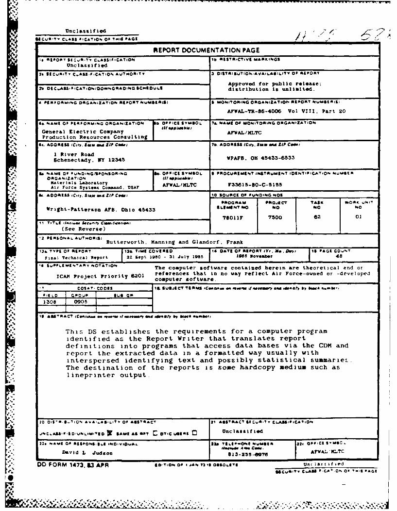
This DS establishes the requirements for a computer programidentified as the Report Writer that translates reportdefinitions into programs that access data bases via the CDM andreport the extracted data in a formatted way usually with
interspersed identifying text and possibly statistical summarieL.The destination of the reports is some hardcopy medium such asI ineprinter output.
04 5S0$_.CftO AVA'6S.L'TV Of ASSTR*CT 21 ASST0RACT S&CW.R?,y CLASP0,CATift
JNC6ASt0'1EOUNLIDMIO r SAME AS NOT I O. C VSI$ Unclassified
22. ftME O AEiPON91964 INO¥VIOUAL 22& TIIEP004mONE hUM6R n Opp'Ml 6,S0C106coame A M Coe
David L Judson 913-253-0976 AriAL 'MI'C
DO FORM 1473, 53 APR Go,74oN Of a os o"t UnC 1 ar ; i fi
S&CuiTy CLASS aIC.0'. 06 '.S ,V-1A
lie

11. Title
Integrated Information Support System (IISS)Vol VIII - User Interface SubsystemPart 20 - Report Writer Development Specification
A S D 86 00369 Jan 1986
:0,ce:st on For:TIS GRA&I
,7 TAB
"","f , catior
.Li t .'
6Ad
A.,',.5b ~ t, o e
F'p
,,.
d."
a.,
a°
a.U,
a.
DS 6201445011 November 1985
-'' PREFACE
This development specification covers the work performedunder Air Force Contract F33615-80-C-5155 (ICAM Project 6201).This contract is sponsored by the Materials Laboratory, Air
, Force Systems Command, Wright-Patterson Air Force Base, Ohio.It was administered under the technical direction of Mr. GeraldC. Shumaker, ICAM Program Manager, Manufacturing TechnologyDivision, through Project Manager, Mr. David Judson. The PrimeContractor was Production Resources Consulting of the GeneralElectric Company, Schenectady. New York, under the direction ofMr. Alan Rubenstein. The General Electric Project Manager wasMr. Myron Hurlbut of Industrial Automation Systems Department.Albany, New York.
Certain work aimed at improving Test Bed Technology hasbeen performed by other contracts with Project 6201 performingintegrating functions. This work consisted of enhancements to
- Test Bed software and establishment and operation of Test Bed" hardware and communications for developers and other users.
Documentation relating to the Test Bed from all of thesecontractors and projects have been integrated under Project 6201for publication and treatment as an Integrated set of documents.The particular contributors to each document are noted on the
.' Report Documentation Page (DD1473). A listing and descriptionof the entire project documentation system and how they arerelated is contained in document FTR620100001, Project Overview.
The subcontractors and their contributing activities wereas follows:
TASK 4.2
Subcontractors Role
4 Boeing Military Aircraft Reviewer.Company (BMAC)
D. Appleton Company Responsible for IDEF support,. (DACOM) state-of-the-art literature
search.
" General Dynamics/ Responsible for factory viewFt. Worth function and information
models.
.04 .O. .. 1
" "' i° " " "-'-' '• " '" "' ' " " ".'" "' ' . " '- . " ' "". '" -.. .. -' '

DS 620144501
1 November 1985
Subcontractors Role
Illinois Institute of Responsible for factory viewTechnology function research (IITRI)
.. and information models ofsmall and medium-size business.
North American Rockwell Reviewer.
Northrop Corporation Responsible for factory viewfunction and information
*" models.
Pritsker and Associates Responsible for IDEF2 support.
SofTech Responsible for IDEFO support.
TASKS 4.3 - 4.9 (TEST BED)
Subcontractors Role
Boeing Military Aircraft Responsible for consultation onCompany (BNAC) applications of the technology
and on IBM computer technology.
Computer Technology Assisted in the areas ofAssociates (CTA) communications systems, system
design and integrationA. methodology, and design of the
Network Transaction Manager.
Control Data Corporation Responsible for the Common Data(CDC) Model (CDM) implementation and
part of the CDM design (sharedwith DACOM).
D. Appleton Company Responsible for the overall CDK(DACOM) Subsystem design integration
and test plan, as well as partof the design of the CDM(shared with CDC). DAOOM alsodeveloped the IntegrationMethodology and did the schema
mappings for the ApplicationSubsystems.
IVL .
. .- hi,
* |* ~ ~ I , * . ~ . ~ I P d - .

DS 6201445011 November 1985
Subcontractors Role
Digital Equipment Consulting and support of theCorporation (DEC) performance testing and on DEC
.. software and computer systemsoperation.
McDonnell Douglas Responsible for the support andAutomation Company enhancements to the Network(McAuto) Transaction Manager Subsystem
during 1984/1985 period.
On-Line Software Responsible for programming theInternational (OSI) Communications Subsystem on the
IBM and for consulting on theIBM.
Rath and Strong Systems Responsible for assistance inProducts (RSSP) (In 1985 the implementation and use ofbecame McCormack f Dodge) the MRP II package (PIOS) that
they supplied.
* SofTech, Inc. Responsible for the design andimplementation of the NetworkTransaction Manager (NTM) in1981/1984 period.
Software Performance Responsible for directing theEngineering (SPE) work on performance evaluation
and analysis.
. Structural Dynamics Responsible for the UserResearch Corporation Interface and Virtual Terminal(SDRC) Interface Subsystems.
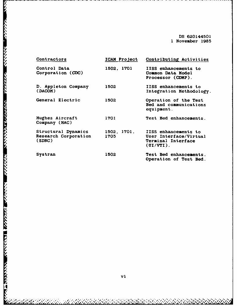
Other prime contractors under other projects who havecontributed to Test Bed Technology, their contributingactivities and responsible projects are as follows:
Contractors ICAM Project Contributing Activities
Boeing Military 1701. 2201, Enhancements for IBMAircraft Company 2202 node use. Technology(BMAC) Transfer to Integrated
Sheet Metal Center(ISMC).
v
U , e .' . -- - .- ', ... .. .... • a -
DS 6201445011 November 1985
Contractors ICAM Project Contributing Activities
Control Data 1502, 1701 IISS enhancements toCorporation (CDC) Common Data Model
Processor (CDMP).
D. Appleton Company 1502 IISS enhancements to(DACOM) Integration Methodology.
General Electric 1502 Operation of the TestBed and communicationsequipment.
Hughes Aircraft 1701 Test Bed enhancements.Company (HAC)
Structural Dynamics 1502. 1701, IISS enhancements toResearch Corporation 1703 User Interface/Virtual(SDRC) Terminal Interface
(UI/VTI).
Systran 1502 Test Bed enhancements.Operation of Test Bed.
vi
DI

, DS 620144501
1 November 1985
TABLE OF CONTENTS
Page
SECTION 1.0 SCOPE ................................... 1-11.1 Identification ........................ 1-11.2 Functional Summary ...................... 1-1
SECTION 2.0 DOCUMENTS ............................... 2-12.1 Reference Documents ..................... 2-12.2 Terms and Abbreviations ................ 2-2
SECTION 3.0 REQUIREMENTS ..... ....................... 3-13.1 Computer Program Definition ............ 3-13.1.1 System Capacities ..................... 3-13.1.2 Interface Requirements ............... 3-13.1.2.1 Interface Block Diagram ........... 3-13.1.2.2 Detailed Interface Definition ..... 3-43.2 Detailed Function Requirements ........ 3-4
. 3.2.1 User's View of the Report ............ 3-53.2.2 Textual Output ...................... 3-53.2.3 Stretchy Lines ...................... 3-53.2.4 Statistical SiuaArization ........... 3-53.2.5 Picture Specifications ............... 3-63.2.6 Nonduplication of Item Values ....... 3-63.2.7 Exceptional Conditions ............... 3-63.2.7.1 Change Condition .................... 3-63.2.7.2 Overflow Condition ................. 3-73.2.7.3 Startup Condition .................. 3-73.2.7.4 Exception Actions .................. 3-73.2.7.4.1 Page Option ....................... 3-73.2.7.4.2 Present Option ................... 3-73.2.7.4.3 Set Option ........................ 3-73.2.7.4.4 Signal Overflow Option .......... 3-83.2.7.4.5 Select Option ..................... 3-83.2.8 Instantiation Rules ................... 3-83.2.9 Graphical Display ..................... 3-83.2.9.1 Graph Definition .................... 3-93.2.9.2 Additive Versus Absolute Display .. 3-103.2.9.3 Axis Information .................... 3-103.2.9.4 Background Color .................... 3-113.2.9.5 Curve Information .................. 3-113.2.9.6 Grids ............................. 3-113.2.9.7 Legends ........................... 3-113.2.9.8 Margins ........................... 3-123.2.9.9 Pie Charts ........................ 3-123 .2 .9 .10 Text .............................. 3-12
vii
6 1-4r: --

DS 6201445011 November 1985
3.2.10 Hierarchical Report Writer ......... 3-133.2.11 Data Structures ..................... 3-133.3 Performance Requirements .............. 3-173.3.1 Programming Methods ................. 3-17
- 3.3.2 Program Organization ................ 3-183.3.3 Expandability ....................... 3-18
. 3.4 Data Base Requirements ................ 3-183.4.1 Sources and Types of Input .......... 3-183.4.2 Destinations and Types of Outputs ... 3-19
SECTION 4.0 QUALITY ASSURANCE PROVISIONS ............ 4-14.1 Introduction and Definitions .......... 4-14.2 Computer Programming Test and
Evaluation ............................ 4-1
SECTION 5.0 PREPARATION FOR DELIVERY ................ 5-1
APPENDICES
APPENDIX A Instantiation Rules ...................... A-1B Semantics of Conditions and Actions ...... B-1C Report Writer Syntax Rules ............... C-I
FIGURES
3-1 Interface Block Diagram ................. 3-23-2a Field Data Structures ................... 3-143-2b Report Generation Data Structures ....... 3-16
3-3 Hierarchical Report Writer DataStructures .............................. 3-17
viii

1 November 1985
SECTION 1
SCOPE
1.1 Identification
This specification establishes the performance,development, test and qualification requirements of a computerprogram identified as the Report Writer (RW). The RW is oneconfiguration item of the Integrated Information Support System(IISS) User Interface (UI).,
4 1.2 Functional Summary
-- This Computer Program Configuration Item (CPCI) is used toreport selected information stored in the database accessiblethrough the Common Data Model (CDM).
The major functions of the Report Writer are:
1. The placement and formatting of fixed textualinformation and database information, i.e. CDMdata.
2. The summarization of simple statistical attributes
of the reported information such as counts, sums,and averages.
),.3. The retrieval of data from the CDM.
"4 N.+'
a
,L w 1,1
MA

DS 6201445011 November 1985
SECTION 2
VDOCUMENTS
2.1 Reference Documents,.4
[1] Structural Dynamics Research Corporation, TerminalOperator Guide, OM 620144000 , 1 November 1985.
[2] Structural Dynamics Research Corporation, IISS FormProcessor User Manual, UM 620144200B, 1 November 1985.
[3] General Electric Company, System Design Specification,7 February 1983.
[4] Structural Dynamics Research Corporation, FormsLanguage Compiler Development Specification, DS620144401B, 1 November 1985.
[5] Structural Dynamics Research Corporation, Forms DrivenForm Editor Development Specification, DS 620144402B,1 November 1985.
[6 Structural Dynamics Research Corporation, ReportWriter Development Specification, DS 620144501 , 1November 1985.
[7) Structural Dynamics Research Corporation, RapidApplication Generator Development Specification, DS620144502 , 1 November 1985.
[8] Structural Dynamics Research Corporation, Text EditorDevelopment Specification, DS 620144600B, 1 November1985.
[9] Structural Dynamics Research Corporation, ApplicationV Interface Development Specification, DS 620144700 1
November 1985.
[10] Structural Dynamics Research Corporation, UserInterface Services Development Specification, DS620144100B, 1 November 1985.
[11] Structural Dynamics Research Corporation, FormProcessor Development Specification, DS 620144200B, 1November 1985.
2-1
9'1
DS 6201445011 November 1985
112] Structural Dynamics Research Corporation, VirtualTerminal Interface Development Specification, DS620144300B, 1 November 1985.
[133 Systran, ICAM Documentation Standards, 15 September1983.
[14] Systran, User's Manual for the ICAM Integrated SupportSystem (IISS) Neutral Data Manipulation Language(NDML), February, 1983.
[15] Systran, Implementation of Enhancements of NDML SELECTCOMMAND, 25 July 1984, revised 9 September 1984.
[16] Systran, Discussion of Function Implementation NDMLSELECT COMMAND, 25 July 1984, revised 4 September1984.
2.2 Terms and Abbreviations
Application Generator: (AG), subset of the IISS UserInterface that consists of software modules that generate IISSapplication code and associated form definitions based on alanguage input. The part of the AG that generates reportprograms is called the Report Writer. The part of the AG thatgenerates interactive applications is called the RapidApplication Generator.
Application Interface: (AI), subset of the IISS UserInterface that consists of the callable routines that are linkedwith applications that use the Form Processor or VirtualTerminal. The AI enables applications to be hosted on computersother than the host of the User Interface.
Application Process: (AP), a cohesive unit of software thatcan be initiated as a unit to perform some function orfunctions.
Attribute: field characteristic such as blinking,highlighted, black, etc. and various other combinations.Background attributes are defined for forms or windows only.Foreground attributes are defined for items. Attributes may bepermanent, i.e., they remain the same unless changed by theapplication program, or they may be temporary, i.e., they remainin effect until the window is redisplayed.
2-2
'p
o'p 2 ', . .. .' .'..' -- ',,., ,,.,€ , ;. :-' .' .N ) ; N hg .;

DS 6201445011 November 1985
Common Data Model: (CDM), IISS subsystem that describes com* -data application process formats, form definitions, etc. of the
IISS and includes conceptual schema, external schemas, internalschemas, and schema transformation operators.
Computer Program Configuration Item: (CPCI), an aggregationof computer programs or any of their discrete portions, whichsatisfies an end-use function.
Conceptual Schema: (CS), the standard definition used forall data in the CDM. It is based on IDEFl informationmodelling.
Device Drivers: (DD), software modules written to handleN I/O for a specific kind of terminal. The modules map terminal
specific commands and data to a neutral format. Device Driversare part of the UI Virtual Terminal.
-%. Display List: is similar to the open list, except that itcontains only those forms that have been added to the screen andare currently displayed on the screen.
External Schema: (ES), an application's view of the CDM'sconceptual schema.
Field: two-dimensional space on a terminal screen.
Form: structured view which may be imposed on windows orother forms. A form is composed of fields. These fields may bedefined as forms, items, and windows.
," Form Definition: (FD), forms definition language after
compilation. It is read at runtime by the Form Processor.
Forms Definition Language: (FDL), the language in whichelectronic forms are defined.
Forms Driven Form Editor: (FDFE). subset of the FE whichconsists of a forms driven application used to create FormDefinition files interactively.
Form Editor: (FE), subset of the IISS User Interface thatis used to create definitions of forms. The FE consists of theForms Driven Form Editor and the Forms Language Compiler.
Form Hierarchy: a graphic representation of the way inwhich forms, items and windows are related to their parent form.
2-3%V

DS 6201445011 November 1985
Forms Language Compiler: (FLAN), subset of the FE thatconsists of a batch process that accepts a series of formsdefinition language statements and produces form definitionfiles as output.
Form Processor: (FP), subset of the IISS User Interfacethat consists of a set of callable execution time routinesavailable to an application program for form processing.
IISS Function Screen: the first screen that is displayedafter logon. It allows the user to specify the function hewants to access and the device type and device name on which heis working.
Integrated Information Support System: (IISS), a testcomputing environment used to investigate, demonstrate and testthe concepts of information management and informationintegration in the context of Aerospace Manufacturing. The IISSaddresses the problems of integration of data resident onheterogeneous data bases supported by heterogeneous computersinterconnected via a Local Area Network.
4. Item: non-decomposable area of a form in which hard-codeddescriptive text may be placed and the only defined areas whereuser data may be input/output.
Message: descriptive text which may be returned in thestandard message line on the terminal screen. They are used towarn of errors or provide other user information.
Message Line: a line on the terminal screen that is used todisplay messages.
Network Transaction Manager: (NTM), IISS subsystem thatperforms the coordination, communication and housekeepingfunctions required to integrate the Application Processes and
'a- System Services resident on the various hosts into a cohesive
system.
Neutral Data Manipulation Language: (NDML), the commandlanguage by which the CDM is accessed for the purpose ofextracting, deleting, adding, or modifying data.
Operating System: (OS), software supplied with a computerwhich allows it to supervise its own operations and manageaccess to hardware facilities such as memory and peripherals.
I -=
2-4
04
DS 6201445011 November 1985
* Pale: instance of forms in windows that are created* whenever a form is added to a window.
Paging and Scrolling: a method which allows a form tocontain more data than can be displayed with provisions forviewing any portion of the data buffer.
Physical Device: a hardware terminal.
Presentation Schema: (PS), may be equivalent to a form. Itis the view presented to the user of the application.
Qualified Name: the name of a form, item or window precededby the hierarchy path so that it is uniquely identified.
Subform: a form that is used within another form.
"' User Interface: (UI). IISS subsystem that controls theuser's terminal and interfaces with the rest of the system. TheUI consists of two major subsystems: the User InterfaceDevelopment System (UIDS) and the User Interface ManagementSystem (UIMS).
User Interface Development System: (UIDS), collection ofIISS User Interface subsystems that are used by applicationsprogrammers as they develop IISS applications. The UIDSincludes the Form Editor and the Application Generator.
Window: dynamic area of a terminal screen on which
predefined forms may be placed at run time.
-.5
~2-5
w.55

DS 6201445011 November 1985
SECTION 3
REQUIREMENTS
3.1 Computer Program Definition
The Report Writer is used to translate report definitionsinto programs that access data bases via the CDM and report theextracted data in a formatted way usually with interspersedidentifying text and possibly statistical summaries. Thedestination of the reports is some hardcopy medium such aslineprinter output.
The Report Definition Language includes the Form DefinitionLanguage and the CDM Neutral Data Manipulation Language (NDML).The FDL is used to create the report layout and the NDML is usedto map the CDM data to the report forms.
3.1.1 System Capacities
The RW is written in C and COBOL and runs on a DEC VAXminicomputer under the VMS operating system.
3.1.2 Interface Requirements
The COBOL program output by the RW is constrained to becompatible with statement forms expected by the CDM precompiler.
The syntax of the Report Definition Language accepted asinput to FLAN is modeled after the Forms Definition Language andthe Neutral Data Manipulation Language. The Forms DefinitionLanguage is used to describe the report layout but additionalcapabilities such as pagebreaking, overflow conditions as neededfor controlling report output have been added to the languagesyntax. Also, the language syntax for mapping the CDM data tothe report form items is accomplished by NDHL.
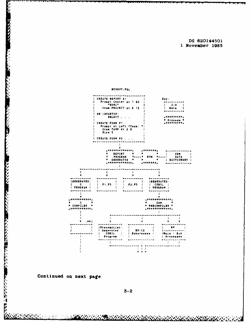
3.1.2.1 Interface Block Diagram
The interface block diagram for the Report Writer is shownin Figure 3-1.
3-
3-1
.
DS 6201445011 November 1985
*----------------------------
1 oy
I r,ProptCanter At 1 60------*- )RC - tT.o
It*@ PROJICT At 6 13I
OR (STARTUPVSILECT
I CREATE FORN P1Prompt At Let, *TaI:
Item TAUK At 2 8 131:: 5
I CREATE PORN P2 . . .
eeeeeee ooe. .... eeee. *............. ** REPORT 0 0 e CDM
* PROGRAM o<... *TH 0<- DATA* GERATOR * * I DICTIORAI I..eOeOOOeeeeeeO. ..eOOOOO. e*............
---------------------------------------------- ------------- -------------V II I I
------- ------ - ----------- ................ . A
C~M3TD I I I@UIATEO;SPI.O F2.PD I COOL
PROGRAM I I I POGAM :
-. ,,,.e ,,.. *e,..,..e:,,..
" C * 0 CDM* COMPLER 0 6 P19COMPILIR
I I I- IV .obj Y V V V
l-I Preeple I I I RP
I 0emerated4; I 23/CS I I-----------------. --- • I COBOL I Subproooes I lMa ! Suab
I Progrem I I PrOOll8la
Continued on next page
3-2

DS 6201445011 November 1985
" COBOL *6 CONPILKI S
.ee...e...
-------- ---- --------------------b I I I I
-. V .obj V .Obj .oj--- --- --- --- -- --- --- --- -- -------
I I Oemerle4e I I 38/CS I I IPI I COBOL I I Subprocees I [Natm I Sub I
---------- --- ---- ---I I S 0 I forM
FI.FD I F2.PD I * LIMIN e---.I PIOCS308------- -------. 1 IUT91FACSI
.eeeeeeeee ee *eeeeeeeeeeee........
I-- I.------------------ - -- . . . ... e c- -
"a" 2 IIOl? FROG&&" a 0 PROCESS
-- - -- - - > 0 IN
bofls 4 Report I -------------------------------.- I D T iAA S3 I
.eooe.es ooooooe* *iermromlcei S
R Report riter e
I
Il Figure 3-1. Report Writer Interface Block Diagram
3-3
04
to I_

DS 620144501
1 November 1985
3.1.2.2 Detailed Interface Definition
The syntax of the Report Definition Language (RDL). isdocumented in Appendix C. This language is intended to provideaccess to all Report Writer functionality.
" The collection of RDL entries that define a reportapplication is a report application definition. A report
* application definition is written to an RDL source file with anytext editor one might use to prepare a program source file.
The RDL source file is processed by the Report WriterGenerator to produce separate binary Form Definition (FD) filesfor each form definition and to generate C and COBOL code which
*j together with the Form Processor (FP) procedures and datadictionary information contained in the Common Data Model (CDM)provide the final report application.
Since the COBOL program contains NDML statements to acquirethe data via the CDM. it must be preprocessed by the CDMprecompiler. After compilation and linking the program isexecuted to produce the report.
If the report is a Hierarchical Report, it is furtherprocessed by the Hierarchical Report Writer (HRW) whichrearranges it into the appropriate tree structure.
3-2 Detailed Function Requir-ements
The RW exploits the versatility of the Forms DefinitionLanguage by extending it in needed ways The reports producedby the RW are similar to forms but differ in two ways. First.they are not interactive when executed, and, second, they arenot scrolled or paged in the same way
The RW generator produces the report application from thedatabase by applying the instantiation rules described inAppendix A to the data structures created by the action of FLANupon the RDL source file The report application produces thereport by accessing the CDM and outputting the data using formprocessor routines
3 4
S
] • . • . -'. . '. . . . . . . • . + .. .- .. .' . . ", .. . . - . *..' * . , .'. - " ..-.' ". * *":, - .

DS 6201445011 November 1985
Vhen a processing error occurs, an error message is output.The error message includes as much information as possible aboutthe nature of the error and the location of the reportapplication statement causing it. If at all possible.processing continues after an error is recognized so thatadditional errors may also be detected.
3.2.1 User's View of the Report
A user should think in terms of what he would like a pageto look like and how the page repeats. The use of conditionsand actions can be used to shape what the report actually willlook like with data.
3.2.2 Textual Output
Text may be associated with the report (form), sub-forms,or field items. The defined text is unchanging throughout thereport. Its placement is governed by giving a location as inthe FDL.
3.2.3 Stretchy Lines
The developer using this CPCI shall be able to defineextensible lines associated with forms and items. The startingand ending locations mean the centers of the given characterpositions. By using relative positions for the ending locationsof lines, the developer can define lines which effectivelystretch to correspond to the length or width of the associatedfield as it expands at run time.
The exact representation of the lines is device dependent.On a particular device the mechanism with the highest resolutionwill be the one implemented. If the device only supportstypewriter graphics. then the dash will be used to constructhorizontal lines and the vertical bar (if available) or theexclamation point will be used to construct vertical lines. Atthe juncture or intersection of two lines a plus sign willreplace the vertical and horizontal characters.
3.2.4 Statistical Summarization
- Certain simple statistical computations may be performedupon Item values and Included in the output. These statisticalsummaries may be Included at the point where an exceptionalcondition arises such as the change of an item field value oranywhere else Eich Item field definition may specify a count.
3-5
.4le € ' . .' .% , .-_. - - . - % " - - . , ' .' ' ' % , .- .- -

DS 6201445011 November 1985
sum, average, minimum, and maximum to be computed and assignedto another item field. The calculated results are alwaysavailable and may be output at any time. When the results arereported, the calculations are reset.
3.2.5 Picture Specifications
Each item field may have a picture specified to define theoutput format, for example, to define the position of a decimalpoint or to include a dollar sign before a decimal number. Morespecifically the editing permitted includes numeric andalphanumeric specification. leading zero suppression, decimal
*i placement. leading sign indicators, currency symbols, andplacement of embedded commas. The picture specification appliesto items that are mapped to CDM data only.
3.2.6 Nonduplication of Item Values
The output of unchanged item values may be suppressed byincluding the NODUP option with the ITEM statement defining thedata field.
3.2.7 Exceptional Conditions
Tests can be established for certain exceptionalconditions, viz. when the addition of an array element wouldcause the array to exceed the bounds of a containing form orwhen an item field changes in value. An action or group ofactions can be specified to occur when the condition arises.The action may be to signal another condition, to repeat theappearance of a form, or to assign a value to an item, forexample.
Practical applications of this facility include output ofheaders, footers, statistical summaries and paging.
The semantics of conditions and actions are given inAppendix B.
3 2.7.1 CHANGE Condition
The change of an item field value can be treated as anexceptional condition which may cause one or more actions tooccur A change of value means a change of value when the itemsare examined in the completed report in the order in which theyare defined to appear by the report definition.
3-6
I

1
DS 620144501
1 November 1985
To be meaningful this facility implies that the item values havebeen sorted before inclusion in the report (probably by use ofthe ORDER option of the SELECT statement used to extract thedata from the CDM).
3.2.7.2 OVERFLOW Condition
This condition is occurs when attempting to add an elementto an open ended array that would exceed the bounds of acontaining form. An open ended array is one which has a star(e.g. °*') specified as the number of elements. The name of thearray element that would cause the overflow is part of thecondition.
3.2.7.3 STARTUP Condition
A set of actions which are performed when the report isstarted.
3.2.7.4 Exception Actions
3.2.7.4.1 PAGE Option
When the condition to which this action is attached occurs,this option causes a physical page eject.
3.2.7.4.2 PRESENT Option
This option begins the instantiation of the specified form(instantiation rules are listed in appendix A). Data which wasobtained through the prior use of a SELECT option is moved tothe forms.
PRESENT has two syntactical forms. In the first a formname and possibly a window are specified. This causes theremoval of any form in the specified window and adds the
a'. specified form to the specified window and then instantiation ofthe form. If no window is specified then 'screen;' is used. Inthe second syntactical form, a qualified name of a form isgiven. This simply begins instantiation of the form which isalready in the form hierarchy.
3.2.7.4.3 SET Option
This option allows the setting of an item field to aspecified value, either an integer or string constant.
3-7

DS 6201445011 November 1985
3.2.7.4.4 SIGNAL OVERFLOW Option
This option allows one exceptional condition to be used totrigger another exceptional condition.
- 3.2.7.4.5 SELECT Option
This option describes what information is desired from theCDM and how it maps to ITEMs on the forms. SELECT will performa query and make the results availble. A PRESENT action mustthen be performed to move the data into the forms.
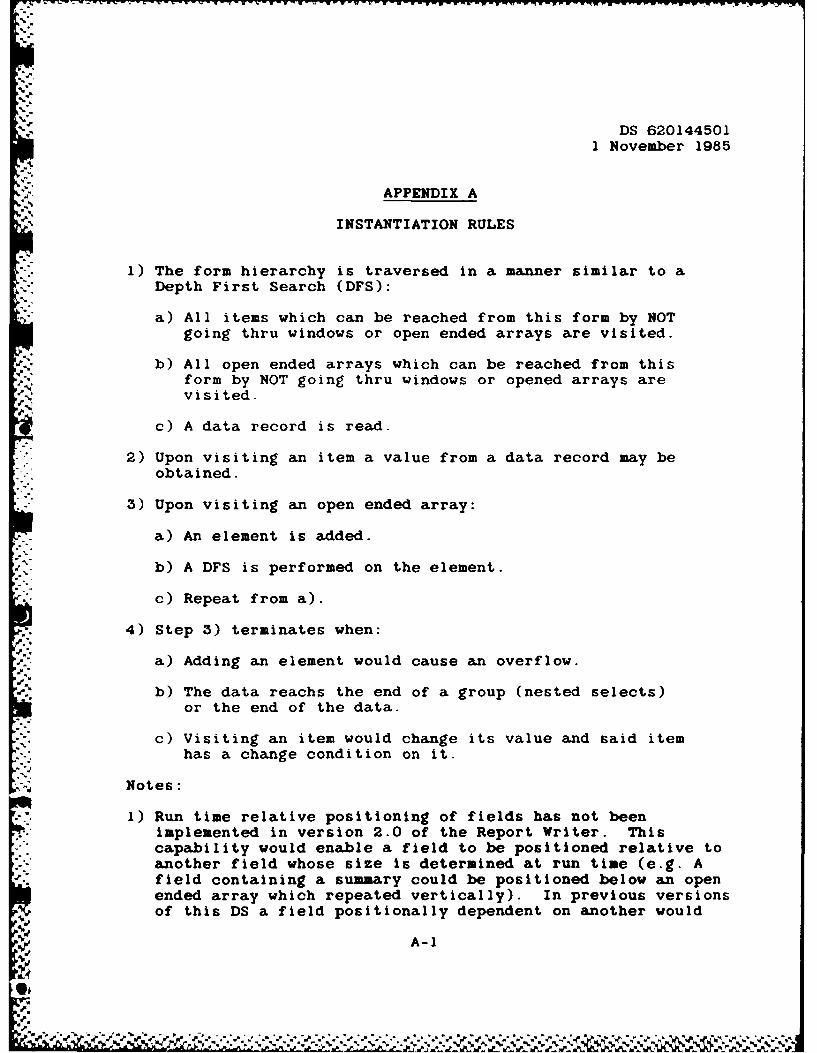
3.2.8 Instantiation Rules
Instantiation of fields on the report is controlled by a
set of rules given in Appendix A.
3.2.9 Graphical Display
The Report Writer will provide the capability tographically display data in two-dimensional format using commonbusiness graphics. The RW will provide this through a field,the graph field, which may contain a single graph of predefinedtype and structure. The available types are bar chart, piechart, and x-y plot. In the case of bar charts and x-y plotsmore than one data set may be plotted in a single graph yieldingmultiple curves or parallel or stacked bars, for example.
Size and location values are in terms of the defaultterminal character sizes and positions. No scaling is doneautomatically; it is the user's responsibility to ensure thattextual information, for example, is of the proper size to fitin the available space. Portions of a graph which do not fit ina displayed space are clipped, not wrapped. The RW will attemptto adjust graphs appropriately for the aspect ratio of thedevice on which they are displayed so that, for example, piecharts are circles regardless of the display device.
Optional attributes will have reasonable default values sothat a graph can be included in a display with a minimum ofeffort at specification. Attributes unsupported on a givendevice, for example color on a monochrome device, will defaultto appropriate values.
3-8

v-.
DS 6201445011 November 1985
On devices supporting them, capabilities shall include thechoice of line style and width (e.g. solid, dashed, dotted,thin, and thick), and the choice of color of the curve, thebackground, and the area under the curve. Other choices shallalways be available including the specification of the size andfont style of text in axis labels, tick mark labels, and legend
"V entries, the lower and upper limits of axes, the scale (linearor logarithmic) of the axes, the presence or absence of a grid,the sizes of the margins between the borders of the graph fieldand the graph, some shading pattern below the curves, symbols toappear at the data points, and for pie charts the amount ofexplosion of individual segments as well as the appearance andlocation (inside or outside) of the actual numerical valuesand/or the percentages represented by each segment. For graphsconsisting of more than one curve or more than one set of barsthere shall also be the option of displaying the data additivelyor absolutely as measured on the vertical axis.
Graphs shall be for output display only. In particular,although the cursor position may be detected within the graphfield, no smaller portion of the graph field may be picked, normay any data points be picked or altered interactively.
J. The data sources for the graphs denoted by ordinate and/orA abscissa in the language syntax are numeric repeating item
fields. The item fields may or may not be displayed as formfields. If they are input fields, then data in them can bealtered and the next time the graph using those fields isdisplayed it will reflect the new values. Graph fields cannotbe be presented in windows because the information defining themappears in part in the field definition of the CREATE FORMstatement and in part in the CREATE GRAPH statement.
The following paragraphs explain the language featuresdescribing graphs in somewhat more detail.
3.2.9.1 Graph Definition
The graph field is defined as a field on a form in the sameway as other fields. The graph field must also appear in aCREATE GRAPH statement. The size and location are requiredparts of the graph field definition. All other attributes ofthe graph field definition are optional.
S3-9
DS 6201445011 November 1985
3.2.9.2 Additive Versus Absolute Display
When data are displayed using bar charts or x-y plots, morethan one dependent data set may be plotted in a given graph.Two or more curves are distinguishable by color or linestyle forexample. The ordinate values can be measured on the verticalaxis either relative to the horizontal axis or relative to acurve already displayed. The former method is absolute displayand the latter additive display. If the graph is a bar chart,the bars will be displayed side by side if the display isabsolute and displayed stacked vertically if the display isadditive. By default displays will be absolute.
3.2.9.3 Axis Information
*Axis labels and tick mark labels can be specifiedindependently for the horizontal and vertical axes. The text inthese labels can be defined to have an available font, color,and size (in units of the terminal's standard character heightand width). By default text will have a size of I by 1 and asimple stick figure font; the color will be the defaultcontrasting color to the background, e.g. white on black. Thecolor of the axis itself including tick marks can also bespecified and may differ from the color of the labels.
The tick mark clause specifies the number of major tickmarks and optionally the number of minor divisions between eachpair of major tick marks. The tick mark label string comprisesa sequence of substrings each delimited by a chosen characternot appearing elsewhere in the string. If the number ofsubstrings is fewer than the number of major tick marks, thenthe tick mark label string is reused from the beginning.
If no label string is defined for an axis, the associateditem field name is used as the label. In the case that morethan one item field is associated with a vertical axis, the nameof the first such item field is used. If no tick mark labelstring is defined, then the axis is divided into a number ofintervals which yields nice tick mark label values. Nice valuesare defined to be multiples by powers of ten of values in theset { .1, .2, .25, and .5).
The lower and upper limits and the scale (linear orlogarithmic) of the axes can be specified also. If the range ofthe data exceeds the limits specified. then data outside therange and not displayed. Unspecified limits are set by defaultto give the smallest range which will span the range of the data
3-10

DS 6201445011 November 1985
such that the tick mark labels can either be those given by theuser or can he ones in the set of nice values as defined in theparagraph above. If the scale is not defined to be logarithmic,then by default it is linear.
.* 3.2.9.4 Background Color
The background of the graph field can be defined to have anavailable color.
3.2.9.5 Curve Information
For x-y plots and in most instances for bar charts severalattributes of the curves or bars may be specified including thecolor of the curve or bars as well as the color or shadingpattern of the area below the curve or bars. On devicessupporting the feature the linetype (solid, dashed, etc.) andlinewidth may also be specified. For x-y plots symbols mayoptionally be placed at the data point locations either in
-addition to or instead of the curve. By default data points areconnected by solid line segments in the order of occurrence ofthe source item field values and no data point symbols appear.The symbols may be chosen from a catalog of predefined symbols
*and will include minimally the dot, plus sign, asterisk, crossor x, and circle. By default no shading occurs below curves orbars and the color is the background color.
3.2.9.6 Grids
Bar charts and x-y plots can be defined to have gridssuperimposed upon them. By default no grid is displayed. Agrid will connect major tick marks in both directions. If minor
* tick marks have been specified, then a fine grid will connectminor tick marks. If minor tick marks have been defined foronly one axis, then fine grid lines will appear perpendicular toonly that axis.
3.2.9.7 Legends
A graph can be defined to have a legend in a specifiedloc.Ltlon. By default no legend will appear. The legend canalso optionally be circumscribed by a box. The location valueis the location of the upper left hand corner of the legendrelative to the graph field. The legend entry is defined in theAXIS or PIE clauses of the CREATE GRAPH statement which may alsocontain specifications of font, size, and color attributes forthe legend entry text.
3-11
• -"4

DS 6201445011 November 1985
3.2.9.8 Margins
The amount of space surrounding the graph which isdelimited by the axes or by the pie is adjustable. This spacecan be set by the MARGIN keyword in the GRAPH field definition.The number given is the percentage of the correspondingdimension of the graph field. By default all margins are 10percent.
3.2.9.9 Pie Charts
There are several language features which apply only to piecharts. Some pie chart attributes are associated withindividual segments. The segments are numbered sequentiallyfrom I beginning at a horizontal radius vector to the right.
The explosion factor which is applied on a segment bysegment basis is the percentage of the radius of the pie bywhich a segment is projected radially outward. By default nosegments are exploded.
The data source for a pie chart is a single item field.The segments correspond in order with the elements of the itemfield. The item field values and/or their corresponding
" percentages of the whole may be displayed for each segmenteither inside or outside the segment. The location is the samefor all segments, but quantities and percentages need not bothbe inside or outside. By default neither the quantities nor thepercentages will appear.
As for other text, color, size, and font may be defined for* quantities, percentages, segment labels, and legend entries.
Finally, each segment may be individually colored or shadedwith a pattern. By default no pattern will appear within thesegments and the interior color will be the background color.
3.2.9.10 Text
Text may be included anywhere within the graph field fortitles, annotation, etc. via the PROMPT clause which is similarto the PROMPT clause generally available within FDL except thathere the text attributes include font and size and, if supportedby the device, color.
3-12
"S.
I . . . . . . . . . . . . ., . . . . . . . . . . , . .

DS 6201445011 November 1985
3.2.10 Hierarchical Report Writer
*i The Hierarchical Report Writer is a post-processor whichaccepts a report containing graphic representations of elementsand connection information as input and rearranges the graphicrepresentations to correspond to the connection information.After rearranging, the resulting tree is either divided intopages (by recursively finding the largest subtree which will fiton a page and moving it onto a separate page) or strips of aspecified width and written out.
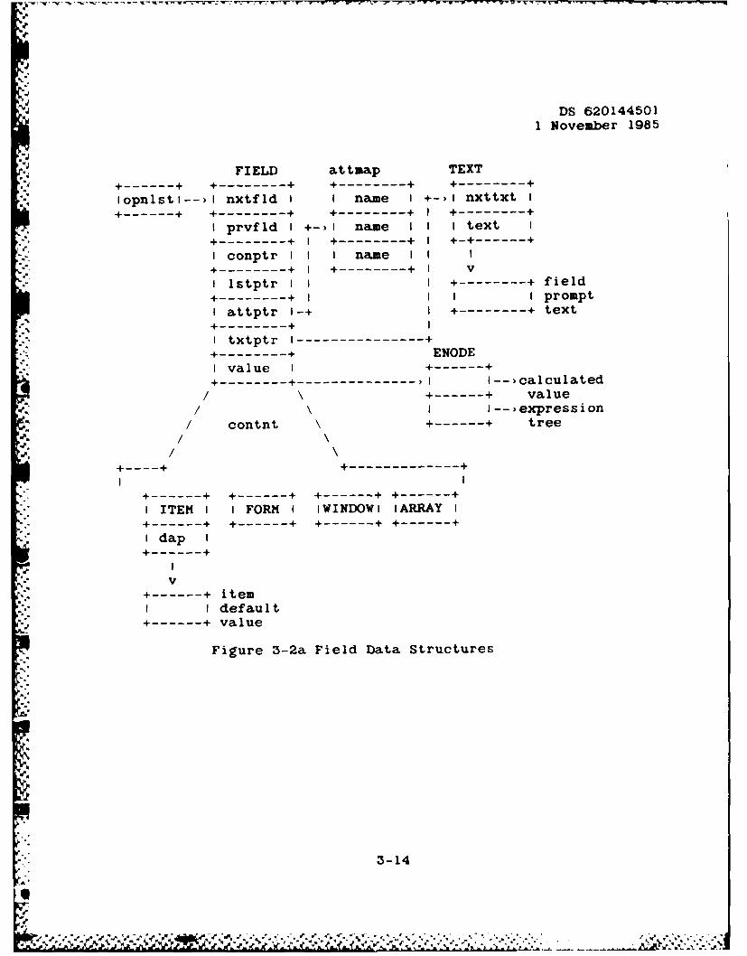
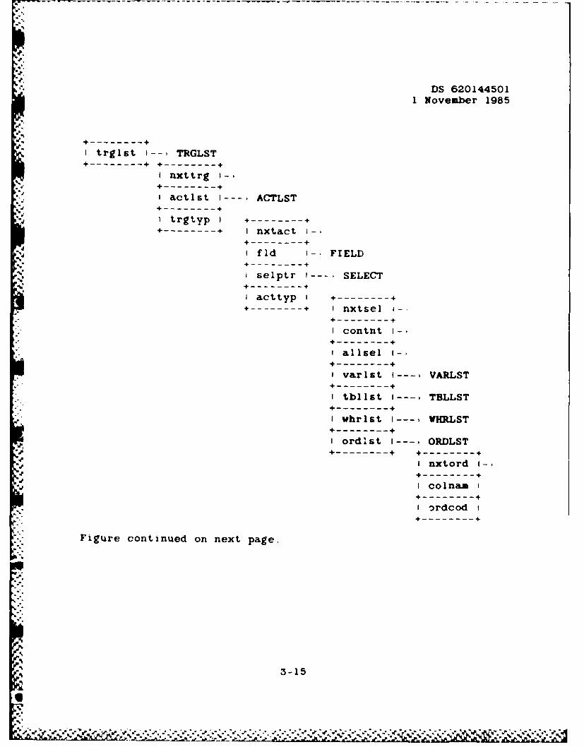
3.2.11 Data Structures
Figures 3-2a and 3-2b below show the data structuresparticular to the report writer application generator. Thefield type data structure is abbreviated in that many structuremembers have been omitted for clarity. These data structuresare created by the Report Writer Generator.
I .i. ... . . . . . . . . S
.3....
WVw..4 * .
DS 620144501
1 November 1985
FIELD attmap TEXT
-------- ---------- ---------- ----------
Iopnlstl-->) nxtfld I I name I +-)I nxttxt I
-------- ---------- + ---------- I ----------
I prvfld I +->I name I I i text I
---------- + I +----------+ +----------
Iconptr I I name II---------- +---------- V
lstptr I +----------+ field+---------- I I promptI attptr I-+ +---------- text----------- +I txtptr I+----------------+---------- ENODE
I-value +--------++ ------------------------ I I--,calculated
/ +--------+ value
/ -- >expression/ contnt -------- + tree
.', /-------------------- +
+-------- -------- -------- -------- +I ITEM I I FORM i iWINDOW I ARRAY I+--------+ +--------+ -------- + +--------I dap I
J I-.- V
-------- + item
I I default+--------+ value
Figure 3-2a Field Data Structures
U'31
4
3-14
DS 6201445011 November 1985
------------
I trglst I- TRGLST+---------- - ---------
I nxttrg I-,+-----------
I actlst I---, ACTLST------------I trgtyp +----------
+---------- I nxtact I-,
+------------ flid I-, FIELD
+------------
I selptr I-. . SELECT+-----------
I acttyp I +--------------------+ I nxtsel i-
+-----------
I contnt I-
+-----------
allsel i-,
+-----------
I varlst I--- VARLST+-----------
I tbllst 1-, TBLLST+-----------
I vhrlst I--- VHLRLST+-----------
I ordlst .... ORDLST----------+ +----------+
I nxtord i-.----------
I colnam I+-----------
I Drdcod i+----------
Figure continued on next page.
3-15

DS 6201445011 November 1985
VARLST VRS------------ -------------
I nxtvar I-, i nxtwhr I-)+----------- +------------
I flid --- FIELD i opl.op2 I -------------- PREDOPER+----------+ +-----------+ +---------+I colna. g i opnd I I optyp I+ ---------- + +----------- +---------
I dtype .--- CDMDTYPE i dtype I--. CDMDTYPE I opnd I---------- + +----------+ +----------- +---------+
I esurep I i dtype I-,+----------+ +---------+
CDMDTY PE
Figure 3-2b Report Generation Data Structures
I
. . ..-

DS 6201445011 November 1985
Figure 3-3 below illustrates the Hierarchical Report Writer datastructures. A node structure exists for each appearance of abox in the final report, but a single module structure existsfor a box regardless of the number of times it appears.
*Node Data Structure Nodule Data Structure----------------- +----------------
I Parent ,- ~INext -
----------------- -----------------
IPrevious 1_- I Node I
- ---------------------------
*I Next - I NameI
----------------- -------------------
iFirst iUsageI
* I Child IICount I
----------------- 4 +----------------
I Last I- Box II Child I Size
+---------------- -----------------
i Module i-bIBox II Margins I
----------------- -----------------
i Next I- i Final II Page I I Position I----------------- 1 (0/1) 1
I X. Y I+---------------IPosition I
-------------------
PageNumber
------------- 4
Figure 3-3 Hierarchical Report WriterData Structures
3 3 Performance Requirements
*3.3.1 Programming Methods
A C &nd COBOL program are used to input the data structurescreated by compiling the FDL source file with RW and theexternal schema data structures from the CDM and output theprogram which produces the report
3-17

DS 6201445011 November 1985
3.3.2 Program Organization
The Report Writer is developed in a modular fashion and maybe combined with the Rapid Application Generator subsystem ofthe UI in the future to add functionality.
The Hierarchical Report Writer is implemented as a separatepost-processor in order to simplify the interfaces and takeadvantage of existing code.
3 3 3 E[pandability
Since the Report Writer is only one facility of severalwhich comprises the complete Application Generator, it isdeveloped with the other application generator capabilities inmind, and in a sense is a prototype for them.
Post-processors other than the Hierarchical Report Writermay be developed in the future to allow for other types ofhierarchical and/or network reports.
3.4 Data Base Requirements
The Report Writer Generator accesses the CDM datadictionary information (the data about the data stored in theCDM) to generate neccessary application code for the ExternalSchemas. It also accesses the Form Processor data structures togenerate necessary application code for processing thePresentation Schemas.
3.4.1 Sources and Types of Input
CDM - Provides characteristic information about theExternal Schema items being used by the application. Themachine representation, the size, and number of positions afterthe decimal point are retrieved from the CDM by the ReportWriter Generator.
Form Definition Objects - Provides Characteristicinformation about the Presentation Schema Items. The machinerepresentation and the picture format are retrieved from theForm Definition objects by the Report Writer Generator.
*" 3-18a'
. . '_I.. . " 0 . . . . " " " -' ' " . . . " " . " . " . . * . . " . . ". " ' _ . . " " ,",9 . . . . . .. . . " ' , . ". . ." ' ' .. .' . . -' . . " " ' . • ". " ". " ". . ". . , -- " % , ,

q
S. DS 620144501
1 November 1985
3 4 2 Destination and Types of Output
Generated External Schema COBOL record structures - The
Report Writer Generator uses the information from the CDM to
create the COBOL record structures for the External Schemas
being used by the application program These structures are
"- part of the generated application code source file.
Generated Presentation Schema COBOL record structures -
The Report Writer Generator uses the Information from the Form
Definition Objects to create the COBOL record structures for thePresentation Schemas being used by the application program
These rtructurei. arc part of the generated application code
source file
Generated Machine Representation Conversion code The
_ Report Writer Generator uses information in the CDM and FormDefinition Objects to create the correct code to go from the
External Schema to the Presentation Schemas and vice versa
This code is part of the generated application code source file
. 1
is
DS 620144501
1 November 1985
SECTION 4
QUALITY ASSURANCE PROVISIONS
4 1 Introduction and Definition
"Testing" is a systematic process that may be preplanned" and explicitly stated Test techniques and procedures may be
defined in advance and a sequence of test steps may bespecified "Debugging" is the process of isolation andcorrection of the cause of an error.
"Antibugging" is defined as the philosophy of writingprogramL in such a way as to make bugs less likely to occur and
* when they do occur, to make them more noticeable to theprogrammer and the user In other words, as much error checkingas is practical and possible in each routine should beperformed
* 4 2 Computer Programing Test and Evaluation
The quality assurance provisions for test consists of thenormal testing techniques that are accomplished during the
* construction process. They consist of design and codewalk-throughs, unit testing, and integration testing. Thesetests are performed by the design team. Structured design.design walk-through and the incorporation of "antibugging"facilitate this testing by exposing and addressing problem areasbefore they become coded "bugs'.
The integration testing entails generating a report*application. precompiling the program with CDMP. compiling the
resultant program, and producing a printed report using a CDMdata base
Each function is tested separately, then the entiresub-system is tested as a unit All testing except forintegration with software belonging to other companies is doneat SDRC on the VAX
4-1

DS 620144501
1 November 1985
SECTION 5
PREPARATION FOR DELIVERY
The implementation site for the constructed software is theIntegrated Support System (IISS) Test Bed site located atGeneral Electric, Albany, New York. The software associatedwith each CPCI release is delivered on a media which iscompatible with the IISS Test Bed. The release is clearlyidentified and includes instructions on procedures to befollowed for installation of the release. Integration with theother IISS CPCI's is done on the IISS Test Bed on a scheduled.-- basis.
:-:.
5-1
'I 5-1
AQ
@ "4 € ' -.. ... , ..' .' ..' .. . -." .. ' .. .; .'° ... . "2 . 2 2 , .. o2 ' ' 2 2 ' ,€ € € ,2 ' ' , €
DS 6201445011 November 1985
APPENDIX A
INSTANTIATION RULES
1) The form hierarchy is traversed in a manner similar to aDepth First Search (DFS):
a) All items which can be reached from this form by NOTgoing thru windows or open ended arrays are visited.
b) All open ended arrays which can be reached from thisform by NOT going thru windows or opened arrays arevisited.
c) A data record is read.
2) Upon visiting an item a value from a data record may beobtained.
3) Upon visiting an open ended array:
a) An element is added.
b) A DFS is performed on the element.
c) Repeat from a).
4) Step 3) terminates when:
a) Adding an element would cause an overflow.
b) The data reachs the end of a group (nested selects)or the end of the data.
c) Visiting an item would change its value and said itemhas a change condition on it.
Notes:
1) Run time relative positioning of fields has not beenimplemented in version 2.0 of the Report Writer. Thiscapability would enable a field to be positioned relative toanother field whose size is determined at run time (e.g. Afield containing a summary could be positioned below an openended array which repeated vertically). In previous versionsof this DS a field positionally dependent on another would
A-1
isAL
DS 6201445011 November 1985
require the other field to be instantiated prior to thedependent field.
2) Since the SELECT action is essentially a static specificationof the query the Report Writer does not check, at run tima,that a field used in a WHERE clause has been instantiated.
A-
.5
A"A-
d'o
"-
.5
5,r
5 : 1!. . _ . " " ,,.,... " ' . . / ... . " '_ .,,°. ' . , , *" ; , - .. ' .. ," . - . . - ) ..
DS 6201445011 November 1985
APPENDIX B
SEMANTICS OF CONDITIONS AND ACTIONS
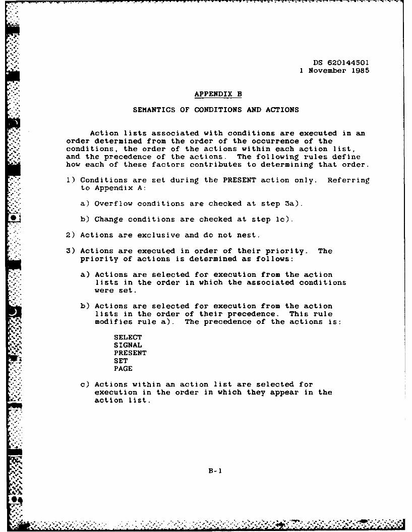
Action lists associated with conditions are executed in anorder determined from the order of the occurrence of theconditions, the order of the actions within each action list,and the precedence of the actions. The following rules definehow each of these factors contributes to determining that order.
1) Conditions are set during the PRESENT action only. Referring
to Appendix A:
a) Overflow conditions are checked at step 3a).
*b) Change conditions are checked at step Ic).
2) Actions are exclusive and do not nest.
3) Actions are executed in order of their priority. Thepriority of actions is determined as follows:
a) Actions are selected for execution from the actionlists in the order in which the associated conditions
*-. were set.
b) Actions are selected for execution from the actionlists in the order of their precedence. This rulemodifies rule a). The precedence of the actions is:
SELECTSIGNALPRESENTSETPAGE
c) Actions within an action list are selected forexecution in the order in which they appear in theaction list.
B-1
'°-

DS 6201445011 November 1985
APPENDIX C
REPORT WRITER SYNTAX RULES
The following is the syntax for the Report Definition
Language.
Report Definition
CREATE REPORT report-name
-" FormDefinition ]
[ Condition Definition ]
* [ Graph-Definition ] ...
Form Definition
CREATE FORM form-name
[ CONDITIONAL)
[ PROMPT Location prompt string ] ...
[ Field Definition ] ...
C-i
-I.
Iq.99.

.. ,.-CA- W** W -u -~ 4
DS 620144501
1. November 1985
Field Definition -Items
ITEM item-name [ RepeatSpec]
Location
[SIZE cols [ BY rows ]
[VALUE (string constant)('. DATE')('.-TIME'){'. _PAGENO'
NODUP I
DISPLAY AS {OUTPUT(TEXT
IDOMAIN ([LEFT I [UPPER) PICTURE picture spec ][RIGHT) [LOWER]
[SUMMARY [BY item-name-i ... I statistic item-naine-2 ...
[PROMPT Location prompt string . ..
[LINE FROM location-i TO location-2 ...
Field Definition - Forms
FORM form-name [ Repeat Spec)
Location
SIZE (cols) [ BY {rows)
[PROMPT Location prompt~string..
[LINE FROM location-i TO location-2 ...
C-2

I .
DS 6201445011 November 1985
Field Definition - Windows
WINDOW window name [ Repeat Spec I
Locat ion
SIZE int [BY int
[ PROMPT Location prompt_string ] ...
C--3S ..
4-..
4p. -
.vi.-..
; .. C-3
@6
.i. 1 ~ ~ ~J V V -~'~-j.9-9-j-~9~ - :-...-& -

DS 620144501
1 November 1985
Field Definition - Graphs
GRAPH graphname
I(ABSOLUTE)I{ADDITIVE)
AXIS {HORIZONTAL)IVERTICAL }
I - -. _ _+
i{LABEL [FONT font] [SIZE size] [COLOR colorli II "string") I
I I{TICK ndiv [minor] II [FONT font] [SIZE size] [COLOR color] II "string") I
I [MINIMUM lower limit]I [MAXIMUM upper_limit]
I SCALE (LINEAR) II {LOGIO I ii (LOG }i
I+--__
[BACKGROUND color]
IGRID {YES I(NO )I{FINE)
[LEGEND Location [BOX]]
Location
' IMARGIN (LEFT ) margin II RIGHT) margin I
(ABOVE) margin I(BELOW) margin I
C-4
* . f *w p p
:, , . .- .': T t,' i, .r ft t'** . , r r " " "- ' ' f --- ,

- DS 6201445011 November 1985
,PROMPT Location [FONT font] [SIZE size] [COLOR color] Iprompt_ string
SIZE cols BY rows
ITYPE (BAR ) iI (PIE )
.I (PLOT)
+ .... +
Repeat Spec4.. ..
( S {HORIZONTAL) [WITH int SPACES] [ ... 3) I
.I { VERTICAL }
Location
I [ int ] (LEFT ) OF (field name]) +-..{ (RIGHT) I AND- (COLUMN int I +-
{ [ int ] { BELOW } [ fieldname I ) -+{ ( (ABOVE } i
I ({ ROW int }-+
S[ int ] { ABOVE ] [fieldname ] ) +-
(BELOW ) lAND{ (ROW int +-
[Rpt] ATI ( ( mnt J(RIGHT )OF [ field name JI-I ( (LEFT) a
{ COLUMN int -+
{ [ int ] LEFT ]OF [ Rpt OF][ field-name]I ( (RIGHT)
S{ [ int ] {ABOVE } Rpt OF] [field-name] )({ ( BELOW)
Int-I int-2 (RELATIVE TO [Rpt OF] [fieldname] }
C-5

DS 6201445011 November 1985
1Rpt
I TOP LEFT ITOP I
I TOP RIGHT II LEFT' CENTERI RIGHTI BOTTOM LEFT I
I BOTTOM IIBOTTOM RIGHT I
Condition Definition
" /\
I (OVERFLOW BY field name) Condition Action ...ON ( (CHANGE item name) ConditionAction ...
I (STARTUP) Condition Action ...
Condition Action
/\
I PAGEI PRESENT (field ) I
(form [IN window]) ISET item name - constant
I SIGNAL OVERFLOW BY field name II Select action I
\ /
C-6
06
DS 6201445011 November 1985
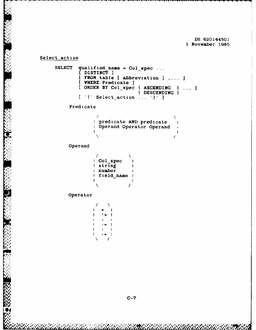
Select action
SELECT qualified name -Col_spec ...
DISTINCT IFROM table [ abbreviation I ..
WHERE Predicate3ORDER BY Col spec {ASCENDING
DESCENDING[{'Select action I
Predicate
Ipredicate AND predicate IOperand Operator Operand
Operand
ICol specstringnumberIfield-nameI
Operator
/C-7

DS 6201445011 November 1985
Colspec
I column< table columnI abbreviation column I
i .8
o f.-o.
%C-8
'.4
DS 6201445011 November 1985
~.i.
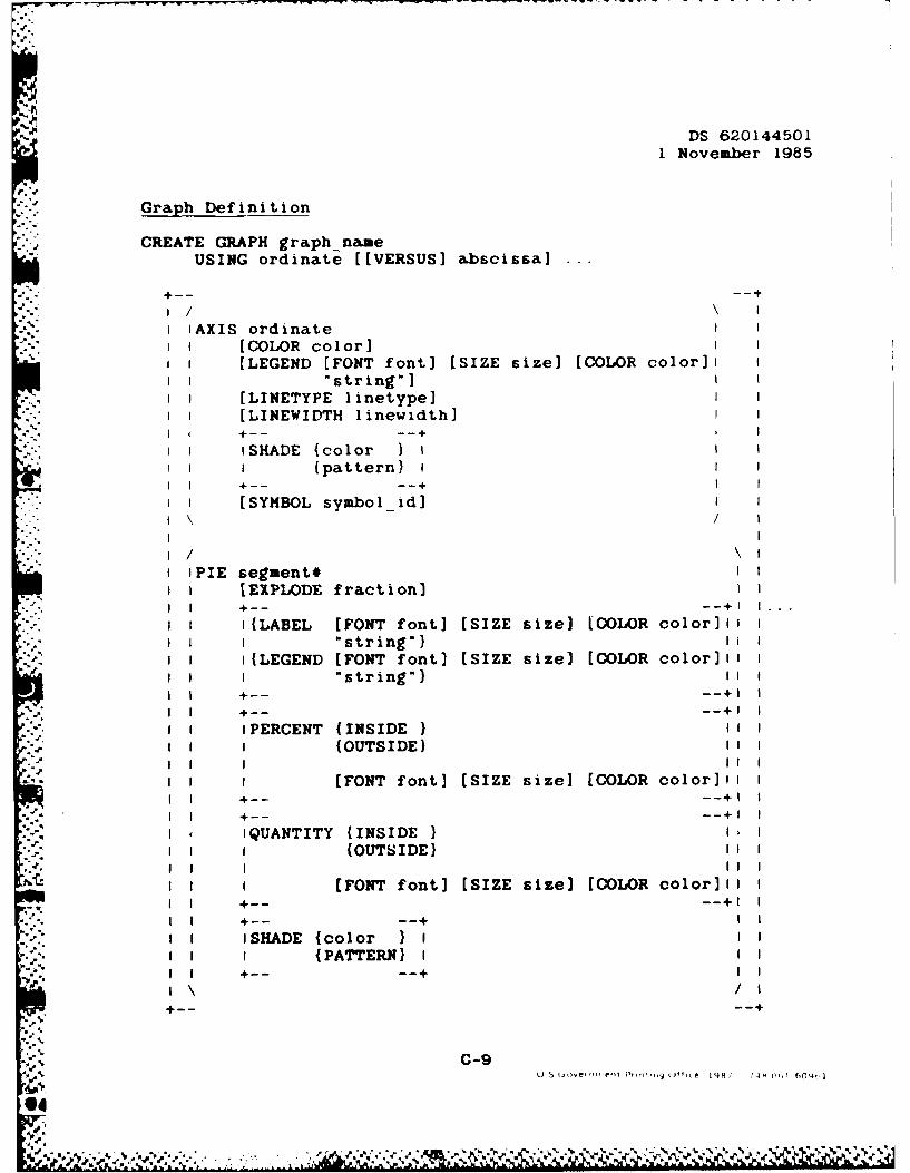
Graph Definition
CREATE GRAPH graph nameUSING ordinate [[VERSUS] abscissa]
,, 4--- - -4+"I "/ \
I AXIS ordinate"I. [COLOR color]
I [LEGEND [FONT font] [SIZE size] [COLOR color] II I "string"]
I ! , [LINETYPE linetype],,I [LINEWIDTH linewidth)
I I ISHADE {color I II I I (pattern) i I II- I +-- --.. +
[SYMBOL symbol id]/ I
I 'PIE segment#
.1 1 [EXPLODE fraction)I .. ,-- .... + .
I I(LABEL [FONT font] [SIZE size] [COLOR color] *II I "string") 11 1I I ILEGEND [FONT font) (SIZE size] [COLOR color]l i
II I string") iii
.I I 1PERCENT (INSIDE ) II." I (OUTSIDE) I1I-I I
.. I I[FONT font] [SIZE size] [COLOR color]0i II__--+1
I ( iQUANTITY (INSIDE ) I
- . I (OUTSIDE) I"I - I II
I I [FONT font] [SIZE size] [COLOR color]l I
I I. ISHADE {color ) I• ~. I (PATTERN) I
I'"\ /4--- ---
5$ C-9
04
%"~'V/'.V - C '. ~ > X ~ h!V

J-WWW
4p 0 p