systemc viterbi documentation
TRANSCRIPT

SystemC Viterbi DocumentationRelease 0.0.1
Pedro Cuadra, Meghadoot Gardi
Jul 09, 2017


Contents
1 Development Environment 31.1 Install SystemC Library . . . . . . . . . . . . . . . . . . . . . . . . . . . . . . . . . . . . . . . . . 31.2 Build the code . . . . . . . . . . . . . . . . . . . . . . . . . . . . . . . . . . . . . . . . . . . . . . 41.3 Build the docker container . . . . . . . . . . . . . . . . . . . . . . . . . . . . . . . . . . . . . . . . 41.4 Run Tests . . . . . . . . . . . . . . . . . . . . . . . . . . . . . . . . . . . . . . . . . . . . . . . . . 41.5 View Simulation Results . . . . . . . . . . . . . . . . . . . . . . . . . . . . . . . . . . . . . . . . . 51.6 Git Workflow . . . . . . . . . . . . . . . . . . . . . . . . . . . . . . . . . . . . . . . . . . . . . . . 6
2 Building System 7
3 Testing Framework 93.1 Testing Building System . . . . . . . . . . . . . . . . . . . . . . . . . . . . . . . . . . . . . . . . . 103.2 APIs . . . . . . . . . . . . . . . . . . . . . . . . . . . . . . . . . . . . . . . . . . . . . . . . . . . 103.3 Test Example . . . . . . . . . . . . . . . . . . . . . . . . . . . . . . . . . . . . . . . . . . . . . . . 113.4 Future Work . . . . . . . . . . . . . . . . . . . . . . . . . . . . . . . . . . . . . . . . . . . . . . . 11
4 Utilities 134.1 Viterbi Path Structure . . . . . . . . . . . . . . . . . . . . . . . . . . . . . . . . . . . . . . . . . . 134.2 Lookup Tables Utilities . . . . . . . . . . . . . . . . . . . . . . . . . . . . . . . . . . . . . . . . . 14
5 Common Components 175.1 Clock Divider . . . . . . . . . . . . . . . . . . . . . . . . . . . . . . . . . . . . . . . . . . . . . . 175.2 Serializer . . . . . . . . . . . . . . . . . . . . . . . . . . . . . . . . . . . . . . . . . . . . . . . . . 195.3 Shift Register . . . . . . . . . . . . . . . . . . . . . . . . . . . . . . . . . . . . . . . . . . . . . . . 22
6 Viterbi Encoder 276.1 Viterbi Encoder . . . . . . . . . . . . . . . . . . . . . . . . . . . . . . . . . . . . . . . . . . . . . . 276.2 Viterbi Encoder (with Lookup Tables) . . . . . . . . . . . . . . . . . . . . . . . . . . . . . . . . . . 326.3 Convolution . . . . . . . . . . . . . . . . . . . . . . . . . . . . . . . . . . . . . . . . . . . . . . . 36
7 Viterbi Decoder 397.1 Viterbi Decoder . . . . . . . . . . . . . . . . . . . . . . . . . . . . . . . . . . . . . . . . . . . . . 39
i

ii

List of Figures
1.1 Encoder Simulation Preview . . . . . . . . . . . . . . . . . . . . . . . . . . . . . . . . . . . . . . . 5
4.1 Viterbi Path Structure . . . . . . . . . . . . . . . . . . . . . . . . . . . . . . . . . . . . . . . . . . 13
5.1 Clock Divider Class Diagram . . . . . . . . . . . . . . . . . . . . . . . . . . . . . . . . . . . . . . 185.2 Clock Divider Simulation Wave Result . . . . . . . . . . . . . . . . . . . . . . . . . . . . . . . . . . 185.3 Serializer Class Diagram . . . . . . . . . . . . . . . . . . . . . . . . . . . . . . . . . . . . . . . . . 195.4 Serializer Circuit . . . . . . . . . . . . . . . . . . . . . . . . . . . . . . . . . . . . . . . . . . . . . 215.5 Serializer Simulation Wave Result . . . . . . . . . . . . . . . . . . . . . . . . . . . . . . . . . . . . 225.6 Shift Register Class Diagram . . . . . . . . . . . . . . . . . . . . . . . . . . . . . . . . . . . . . . . 235.7 Shift Register Circuit . . . . . . . . . . . . . . . . . . . . . . . . . . . . . . . . . . . . . . . . . . . 245.8 Shift Register Simulation Wave Result . . . . . . . . . . . . . . . . . . . . . . . . . . . . . . . . . . 25
6.1 Viterbi Encoder Class Diagram . . . . . . . . . . . . . . . . . . . . . . . . . . . . . . . . . . . . . 286.2 Viterbi Encoder Circuit . . . . . . . . . . . . . . . . . . . . . . . . . . . . . . . . . . . . . . . . . . 306.3 Encoder Simulation Wave Result . . . . . . . . . . . . . . . . . . . . . . . . . . . . . . . . . . . . . 326.4 Viterbi Encoder with Lookup Tables Class Diagram . . . . . . . . . . . . . . . . . . . . . . . . . . 336.5 Viterbi Encoder with Lookup Table Circuit . . . . . . . . . . . . . . . . . . . . . . . . . . . . . . . 346.6 Encoder Simulation Wave Result . . . . . . . . . . . . . . . . . . . . . . . . . . . . . . . . . . . . . 366.7 Convolution Block Class Diagram . . . . . . . . . . . . . . . . . . . . . . . . . . . . . . . . . . . . 376.8 Convolution Simulation Wave Result . . . . . . . . . . . . . . . . . . . . . . . . . . . . . . . . . . . 38
7.1 Viterbi Decoder Class Diagram . . . . . . . . . . . . . . . . . . . . . . . . . . . . . . . . . . . . . 407.2 Decoder Simulation Wave Result . . . . . . . . . . . . . . . . . . . . . . . . . . . . . . . . . . . . . 447.3 Decoder Simulation With Errors Wave Result . . . . . . . . . . . . . . . . . . . . . . . . . . . . . . 45
1

SystemC Viterbi Documentation, Release 0.0.1
2 List of Figures

CHAPTER 1
Development Environment
Install SystemC Library
Native Linux Library
To install SystemC, first you have to install some dependencies, by running;
sudo apt-get install build-essential
Download SystemC 2.3 from https://github.com/systemc/systemc-2.3. After downloading, extract it. Now we needto compile and install it by running;
cd <extracted-dir>./configure --prefix=/usr/local/makesudo make install
Docker Container
First install Docker by following;
• Windows Install Instructions
• Linux Install Instructions
Now you should open a shell (e.g. cmd.exe or Powershell for windows; bash or any terminal for linux) and downloadthe pre-built Docker image with SystemC pre-installed. To download the Docker container run;
docker pull pjcuadra/sc_viterbi
To start the container run;
3

SystemC Viterbi Documentation, Release 0.0.1
docker run -d --rm --name systemc -v <your-sc_viterbi-src-code-path>:/root/ \-p 1122:22 pjcuadra/sc_viterbi:latest
Warning: Don’t forget to update the <your-sc_viterbi-src-code-path> placeholder.
Once you have your docker running you can ssh into it as follows;
ssh [email protected] -p 1122
Inside the docker you’ll find your code and you can build it as specified in the section Build the code.
Build the code
Once the dependencies are installed you can build the code by running;
cd <your-sc_viterbi-src-code-path>mkdir buildcd buildcmake ..make
Warning: If you are building inside the docker image the <your-sc_viterbi-src-code-path> is /root/.
Build the docker container
If you want to build the image locally you can do it so. The Dockerfile is provided at ci/Dockerfile. For building theimage run;
cd <your-sc_viterbi-src-code-path>/cidocker build -t pjcuadra/sc_viterbi:latest .
Warning: Dockerfile and the pjcuadra/sc_viterbi image on Docker server shall be on sync. If theres a changeneeded in the image please also change it in the Dockerfile and push the new image to the Docker server.
Run Tests
This project has a newly created testing framework for SystemC. More about the framework here Testing Framework.To run the tests first you need to compile the tests executables by running;
cd <your-sc_viterbi-src-code-path>mkdir buildcd <your-sc_viterbi-src-code-path>/buildcmake ..makemake compile_tests
4 Chapter 1. Development Environment

SystemC Viterbi Documentation, Release 0.0.1
The testing framework uses CTest for running the tests and you can do so by running;
cd <your-sc_viterbi-src-code-path>/buildmake test
The output will look something like;
Running tests...Test project /root/build
Start 1: full_adder_ut1/8 Test #1: full_adder_ut .................... Passed 0.00 secStart 2: clock_divider_ut
2/8 Test #2: clock_divider_ut ................. Passed 0.00 secStart 3: shift_register_ut
3/8 Test #3: shift_register_ut ................ Passed 0.00 secStart 4: serializer_ut
4/8 Test #4: serializer_ut .................... Passed 0.00 secStart 5: convolution_ut
5/8 Test #5: convolution_ut ................... Passed 0.00 secStart 6: encoder_ut
6/8 Test #6: encoder_ut ....................... Passed 0.00 secStart 7: convolution_shiftreg_ut
7/8 Test #7: convolution_shiftreg_ut .......... Passed 0.00 secStart 8: decoder_ut
8/8 Test #8: decoder_ut ....................... Passed 0.00 sec
100% tests passed, 0 tests failed out of 8
Total Test time (real) = 0.04 sec
View Simulation Results
Our testing framework automatically generates a VCD trace file for every test. To view the simulation results youcan use any VCD visualizer software we recommend to use gtkwave. For instance the result of the encoder_ut can beviewed by opening gtkwave and open the file at <your-sc_viterbi-src-code-path>/build/trace/enconder/encoder.vcd.You can also run;
gtkwave <your-sc_viterbi-src-code-path>/build/trace/enconder/encoder.vcd
After adding all signals to the visualization area and adjusting the scale the simulation results looks like in Fig. 1.1.
Fig. 1.1: Encoder Simulation Preview
1.5. View Simulation Results 5

SystemC Viterbi Documentation, Release 0.0.1
Note: Traces are located at <your-sc_viterbi-src-code-path>/build/trace and have the same directory structure as thetests at <your-sc_viterbi-src-code-path>/test/src
Warning: The Docker image doesn’t provide gtkwave you’ll need to install it separately.
Git Workflow
Since we are using Github to host our repository we are mainly using their git workflow. You can read about it at,Github Flow
Furthermore every Pull Request can only be merged back to master branch if it passes all our tests running on CircleCI.
6 Chapter 1. Development Environment

CHAPTER 2
Building System
Our code is completely IDE independent. For supporting the compiling and simulation of the code we had to developour own building system using CMake.
The building system is based on two simple yet powerful CMake macros.
# Add source directoryadd_sources_directory(dir1 dir2 ...)
# Add source fileadd_sources(file1 file2 ...)
The basic idea behind our building system is to specify directories having source codes and inside every directorywith sources specify which files are source files. For example, <your-sc_viterbi-src-code-path>/src/CMakeLists.txt,specifies common, decoder and encoder as sources directories as follows;
# Add source directoryadd_sources_directory(common/
encoder/decoder/)
Furthermore, <your-sc_viterbi-src-code-path>/src/decoder/CMakeLists.txt specifies decoder.cpp as a source code fileas follows;
# Add sourcesadd_sources(decoder.cpp)
Note:
• You can specify source code directories and files in the same CMakeLists.txt file.
• You can specify as many source code directories and files using the same macro call (add_sources_directory(...)and add_sources(...) respectively).
• Every source code directory added using add_sources_directory(...) has to contain a CMakeLists.txt file.
7

SystemC Viterbi Documentation, Release 0.0.1
Our main CMakeLists.txt at <your-sc_viterbi-src-code-path> does the rest;
• Verifies that SystemC and other dependencies are installed on the system.
• Building all the source code as a library
• Link source code with SystemC and other dependencies libraries
• Building the tests using our testing framework described here.
• Link all the tests with the source code and other dependencies
• Enable testing
8 Chapter 2. Building System

CHAPTER 3
Testing Framework
Since there is no robust and reliable unit testing framework for SystemC code, we decide to implement our own testingframework. The goals for the design of the testing framework were;
• Similar to other existing unit testing frameworks like googletest and Junit.
• Intuitive timing specifications checking APIs
• Centralized mechanism to run all unit tests
This goals helped us to overcome the following disadvantages inherit from SystemC traditional testing methodologies;
• sc_start() and sc_stop() calls affect the entire process.
• There’s no API to reset simulation time
• Every unit test has to be written inside a sc_main(...). Meaning a separate executable per test.
• An entire SC_MODULE has to be developed for introducing stimuli to the Module Under Test and an other forverifying it’s output.
Based on this goals we developed a unit testing framework with the following features;
• Centralized method to run all tests through CTest. Review ctest for a full set of features and capabilities inheritedfrom ctest.
• Easy, Intuitive, and Powerful building system.
• Intuitive timing specification checking.
• Simplified test writing structure.
• Simplified tracing APIs and automatic VCD files creation.
• Easy to integrate C++ headers library.
9

SystemC Viterbi Documentation, Release 0.0.1
Testing Building System
The our building system for testing is based on our project’s Building System. The entire tests building system isbased on the following CMake macros;
# Add test sources directoryadd_test_sources_directory(dir1 dir2 ...)
# Add test source fileadd_test_sources(file1 file2 ...)
The usage of both macros is analog to the usage of add_sources_directory(...) and add_sources(...), respectively.Review Building System for more information.
Note: All tests source code have to be located at <your-sc_viterbi-src-code-path>/test/src.
Furthermore, add_test_sources(...) also registers every test source file as a test in CTest. This makes it easier for testrunning through ctest command or make test.
APIs
SC_TEST(test_name)Define a test with a given test name
Parameters
• test_name (string) – The name or label of the test
SC_EXPECT_AT(expected, actual, time_val, time_unit)Check that actual equals expected at a given moment
Parameters
• expected – Expected value
• actual – Actual value
• time_val (double) – Time value
• time_unit (sc_time_unit) – Time unit
Tracing
SC_TRACE(signal, name)Add a signal to the test’s trace file with the provided name
Parameters
• signal (sc_signal) – The signal to be added to the trace
• name (string) – The given name for the signal
SC_STRACE(signal)Add a signal to the test’s trace file
Parameters
10 Chapter 3. Testing Framework

SystemC Viterbi Documentation, Release 0.0.1
• signal (sc_signal) – The signal to be added to the trace (the name of the signal willbe name of the variable)
Test Example
The following code was taken from our clock divider’s test. It is a good example to show how our testing frameworkworks.
1 #include <sc_test_framework.h>2
3 ...4
5 SC_TEST(clock_divider) {6 sc_clock sys_clock("sys_clock", clock_period, clock_duty, clock_start, false);7 sc_signal<bool> div_clock_4;8
9 # Trace signals10 SC_TRACE(sys_clock, "sys_clk");11 SC_STRACE(div_clock_4);12
13 # Create clock divider14 clock_divider<4> div_4 ("DivideBy4");15
16 # Connect Signals17 div_4.clk_in (sys_clock);18 div_4.clk_out (div_clock_4);19
20 # Verify output at a certain point in time21 SC_EXPECT_AT(sc_logic(0), div_clock_4, 200, SC_NS);22 SC_EXPECT_AT(sc_logic(1), div_clock_4, 220, SC_NS);23
24 sc_start(350, SC_NS);25
26 }
Here is a short explanation on what the code does;
• In line 1 the framework headers library is included.
• In line 5 the test is defined with the name clock_divider.
• In line 10 the signal sys_clock is added to the trace file with a given name that differs from the sc_signal variablename.
• In line 11 the signal div_clock_4 is added to the trace file using with with the name div_clock_4.
• In line 21 and 22 the time specification for the signal div_clock_4 is done. If the signal div_clock_4 differs from‘0’ at 200ns or from ‘1’ at 220ns the test will fail.
Future Work
This testing framework is planned to be developed as a separate project because of its usability and scope. It wasincubated in within this project.
3.3. Test Example 11

SystemC Viterbi Documentation, Release 0.0.1
APIs
SC_EXPECT_AFTER(expected, actual, time_val, time_unit)Check that actual equals expected after a specific time interval
Parameters
• expected – Expected value
• actual – Actual value
• time_val (double) – Time value
• time_unit (sc_time_unit) – Time unit
SC_SIGNAL_SET(signal, value, time_val, time_unit)Set the signal to a specific value at a specific point in time
Parameters
• signal – The signal to be set
• value – The value to be taken
• time_val (double) – Time value
• time_unit (sc_time_unit) – Time unit
SC_SETUPSet up everything before the test run
SC_TEARDOWNClean everything up after the test run
12 Chapter 3. Testing Framework

CHAPTER 4
Utilities
Viterbi Path Structure
Class Diagram
The UML diagram of Fig. 4.1 shows the overview of the class.
Fig. 4.1: Viterbi Path Structure
Class Description
template<int output_buffer_bit_size>
13

SystemC Viterbi Documentation, Release 0.0.1
class viterbi_path_sViterbi Path Structure
sc_uint<MAX_METRIC_WIDTH> metric_valueMetric Value
sc_uint<MAX_PATH_WIDTH> path_sizeCurrent size of the path
sc_uint<output_buffer_bit_size> path_outputDecoded value because of the taken path.
bool is_aliveFlags the validity of the information stored in the structure.
inline viterbi_path_s<output_buffer_bit_size> &operator=(const viterbi_path_s<output_buffer_bit_size>&obj)
Overload the = operator
Parameters const viterbi_path_s<output_buffer_bit_size>& obj – Objectto be assign to this instance.
inline bool operator==(const viterbi_path_s<output_buffer_bit_size> &obj) constOverload the == operation
Parameters const viterbi_path_s<output_buffer_bit_size>& obj – Objectto be equal to this instance.
inline friend void sc_trace(sc_trace_file *tf, const viterbi_path_s<output_buffer_bit_size> &obj,const std::string &name)
Enables the tracing of the signal of type viterbi_path_s<output_buffer_bit_size>
Parameters
• sc_trace_file * tf – Trace file pointer
• const viterbi_path_s<output_buffer_bit_size>& obj – Object in-stance to trace.
• const string& name – Signal name
Structure
The structure of the clock divider is trivial since it has only one process.
Lookup Tables Utilities
Functions Description
template<int output, int input, int memory>inline void create_states_lkup(sc_lv<memory * input> *next_state_lkp)
Initialize the next state lookup table.
Parameters sc_lv<memory * input> * next_state_lkp – Pointer to the lookup tableto to be initialized.
template<int output, int input, int memory>
14 Chapter 4. Utilities

SystemC Viterbi Documentation, Release 0.0.1
inline void create_output_lkup(sc_lv<memory * input> polynomials[output], sc_lv<output> *out-put_lkp)
Initialize the output/encoded lookup table.
Parameters
• sc_lv<memory * input> polynomials[output] – Polynomials used to en-code.
• sc_lv<output> * output_lkp – Pointer to the output/encoded lookup table to beinitialized.
4.2. Lookup Tables Utilities 15

SystemC Viterbi Documentation, Release 0.0.1
16 Chapter 4. Utilities

CHAPTER 5
Common Components
This section presents a set of components that are common and are basic building elements for both the encoder andthe decoder.
Clock Divider
Class Diagram
The UML diagram of Fig. 5.1 shows the overview of the class.
Class Description
template<int ratio>class clock_divider
Clock Divider module with clock division ratio
sc_core::sc_in_clk clk_inInput clock at normal rate
sc_core::sc_out_clk clk_outOutput clock at rate of the input clock divided by ratio with the same duty cycle as the input clock.
int divider_counterInternal edges counter
void prc_clock_divider(void)Clock divider main Process
The process counts the positive and negative edges and toggles to sc_logic(‘0’) and sc_logic(‘1’) when theedges are twice the ratio and exact the ratio, respectively.
list sensitivityclk_in.pos(), clk_in.neg()
17

SystemC Viterbi Documentation, Release 0.0.1
Fig. 5.1: Clock Divider Class Diagram
Structure
The structure of the clock divider is trivial since it has only one process.
Simulation Results
The simulation of the clock divider is just create 2 clock divider one with ratio 3 and other with ratio 4. Fig. 5.2 showsthe result of the simulation.
Fig. 5.2: Clock Divider Simulation Wave Result
Note:
• div_clock_3 has 13 of the frequency of sys_clock
• div_clock_4 has 14 of the frequency of sys_clock
• div_clock_3 and div_clock_4 conserve 50% duty cycle
18 Chapter 5. Common Components

SystemC Viterbi Documentation, Release 0.0.1
Serializer
Class Diagram
The UML diagram of Fig. 5.3 shows the overview of the class.
Fig. 5.3: Serializer Class Diagram
Class Description
template<int inputs>class serializer
Clock Divider module with clock division ratio
sc_core::sc_in_clk clk_inInput clock
sc_core::sc_in<sc_core::sc_lv<inputs>> par_inParallel input
sc_core::sc_in_clk ser_trigTrigger the serialization
5.2. Serializer 19

SystemC Viterbi Documentation, Release 0.0.1
sc_core::sc_out<sc_core::sc_logic> ser_outSerialized output
int output_selectorInternal counter for select the bit index to forward to the output
void prc_serializer(void)Serializer main Process
Forwards the current bit to the ser_out. The current bit is calculated using output_selector. The serializa-tion process starts with the ser_trig and ends when the last bit has been forwarded to the output. Afterforwarding the last bit the output is set to sc_logic(‘0’).
list sensitivityclk_in.pos(), ser_trig.pos()
void prc_serializer_counter_update(void)Updates the internal bit selector counter with each positive edge of the clock.
list sensitivityclk_in.pos()
void prc_serializer_counter_reset(void)Reset the internal bit selector counter after a ser_trig positive edge.
list sensitivityser_trig.pos()
Structure
Fig. 5.4 shows the structure of the serializer module.
Simulation Results
The code of the test case of the serializer is shown below;
1 ...2
3 static const int inputs = 8;4
5 SC_TEST(serializer) {6 sc_clock sys_clock("sys_clock", clock_period, clock_duty, clock_start, false);7 sc_signal<sc_logic> ser_out;8 sc_signal<bool> ser_trig;9 sc_signal<sc_lv<inputs> > par_in;
10
11 ...12
13 clock_divider<inputs> clk_div ("CLK_DIV");14
15 ...16
17 serializer<inputs> serializer ("Serializer");18 serializer.ser_out(ser_out);19 serializer.clk_in(sys_clock);20 serializer.par_in(par_in);21 serializer.ser_trig(ser_trig);22
20 Chapter 5. Common Components

SystemC Viterbi Documentation, Release 0.0.1
Fig. 5.4: Serializer Circuit
5.2. Serializer 21

SystemC Viterbi Documentation, Release 0.0.1
23 par_in = sc_lv<inputs>("00000000");24 sc_start(125, SC_NS);25
26 par_in = sc_lv<inputs>("10010010");27 sc_start(400, SC_NS);28
29 }
Note:
• The width of the serializer is 8
• par_in[7:0] is set to 0𝑥92 at 125𝑛𝑠
Fig. 5.5 shows the result of the simulation.
Fig. 5.5: Serializer Simulation Wave Result
Note:
• ser_trig triggers the serialization to ser_out
• par_in[7:0] has a 0𝑥92 and is the value that is actually serialized
• ser_out outputs the MSb first and the LSb at the end
Shift Register
Class Diagram
The UML diagram of Fig. 5.6 shows the overview of the class.
Class Description
template<int width>class shift_register
Clock Divider module with clock division ratio
sc_core::sc_in_clk clkInput clock
sc_core::sc_in<sc_core::sc_logic> data_inInput data to be shifted in
22 Chapter 5. Common Components

SystemC Viterbi Documentation, Release 0.0.1
Fig. 5.6: Shift Register Class Diagram
sc_core::sc_out<sc_core::sc_lv<width>> qStored value of the shift register
sc_core::sc_lv<width> q_stateInternal stored value
void prc_shift_register(void)Shift register main process
Shifts the value one bit to the left and assign data_in to the MSb.
list sensitivityclk.pos()
Structure
Fig. 5.7 shows the structure of the generic shift register. Our implementation doesn’t differ from the generic shiftregister.
Simulation Results
The code of the test case of the shift_register is shown below;
1 ...2
3 static const int reg_width = 5;
5.3. Shift Register 23

SystemC Viterbi Documentation, Release 0.0.1
Fig. 5.7: Shift Register Circuit
4
5 SC_TEST(shift_register) {6 sc_signal<sc_logic> data_in;7 sc_signal<sc_lv<reg_width> > register_state;8 sc_clock sys_clock("sys_clock", clock_period, clock_duty, clock_start, false);9
10 ...11
12 shift_register<reg_width> sregister ("ShiftRegister");13
14 ...15
16 data_in = sc_logic('0');17 sc_start(50, SC_NS);18 data_in = sc_logic('1');19 sc_start(100, SC_NS);20 data_in = sc_logic('0');21 sc_start(100, SC_NS);22 }
Note:
• data_in starts at sc_logic(‘0’)
• data_in toggles to sc_logic(‘1’) at 50𝑛𝑠
• data_in toggles back to sc_logic(‘0’) at 100𝑛𝑠
• Shift Register width is 5
Fig. 5.8 shows the result of the simulation.
Note:
• At 50𝑛𝑠 the shifting of sc_logic(‘1’) starts. The sc_logic(‘1’) is injected at the MSb.
• Between 120𝑛𝑠 and 150𝑛𝑠 the value of register_state[4:0] stays constant at 0𝑥1𝐹 because of the shift register’swidth is set to 5.
24 Chapter 5. Common Components

SystemC Viterbi Documentation, Release 0.0.1
Fig. 5.8: Shift Register Simulation Wave Result
• After 150𝑛𝑠 the shifting of sc_logic(‘0’) starts
• 5 clock cycles after 150𝑛𝑠 the register_state[4:0] is back to 0𝑥0.
5.3. Shift Register 25

SystemC Viterbi Documentation, Release 0.0.1
26 Chapter 5. Common Components

CHAPTER 6
Viterbi Encoder
This section presents two different implementation of the Viterbi encoder. As well as a the implementation of theconvolution block.
Note: Both implementations have the same interface (inputs/outputs) so the can be used interchangeably.
Viterbi Encoder
Class Diagram
The UML diagram of Fig. 6.1 shows the overview of the class.
Class Description
template<int output, int input, int memory>class encoder
Viterbi Encoder
sc_core::sc_in_clk clkInput clock
sc_in<sc_lv<input>> inParallel input to be encoded
sc_in<sc_lv<memory * input>> polynomials[output]Polynomials to convolve with
sc_out<sc_logic> outSerialized encoded output
27

SystemC Viterbi Documentation, Release 0.0.1
Fig. 6.1: Viterbi Encoder Class Diagram
28 Chapter 6. Viterbi Encoder

SystemC Viterbi Documentation, Release 0.0.1
sc_signal<sc_lv<memory * input>> mem_bus_convArranged for convolution memory bus
sc_signal<bool> clk_divDivided clk signal
sc_signal<sc_logic> data_in_drv[memory]Data in driver (distribute to shift registers)
sc_signal<sc_logic> conv_outs[output]Convolution outputs array
sc_signal<sc_lv<output>> conv_par_busParallel convolution outputs bus
sc_signal<sc_lv<memory>> mem_bus[input]Shift registers’ memory buses
convolution<memory * input> *conv_block[output]Convolution Modules
shift_register<memory> *register_bank[input]Shift Registers
clock_divider<output> *clk_dividerClock divider
serializer<output> *serialSerializer for the output
void prc_split_input(void)Split the in every input to connect with each shift register of the bank. There are input shift registers.
list sensitivityin
void prc_update_conv_par_bus(void)Merge all convolution blocks outputs into a single parallel bus.
list sensitivityconv_outs
void prc_arrange_memory_bus(void)Create a single parallel bus merging all parallel buses of all shift registers.
list sensitivitymem_bus
Structure
Fig. 6.2 shows the structure of the our Viterbi encoder implementation without using lookup tables.
Simulation Results
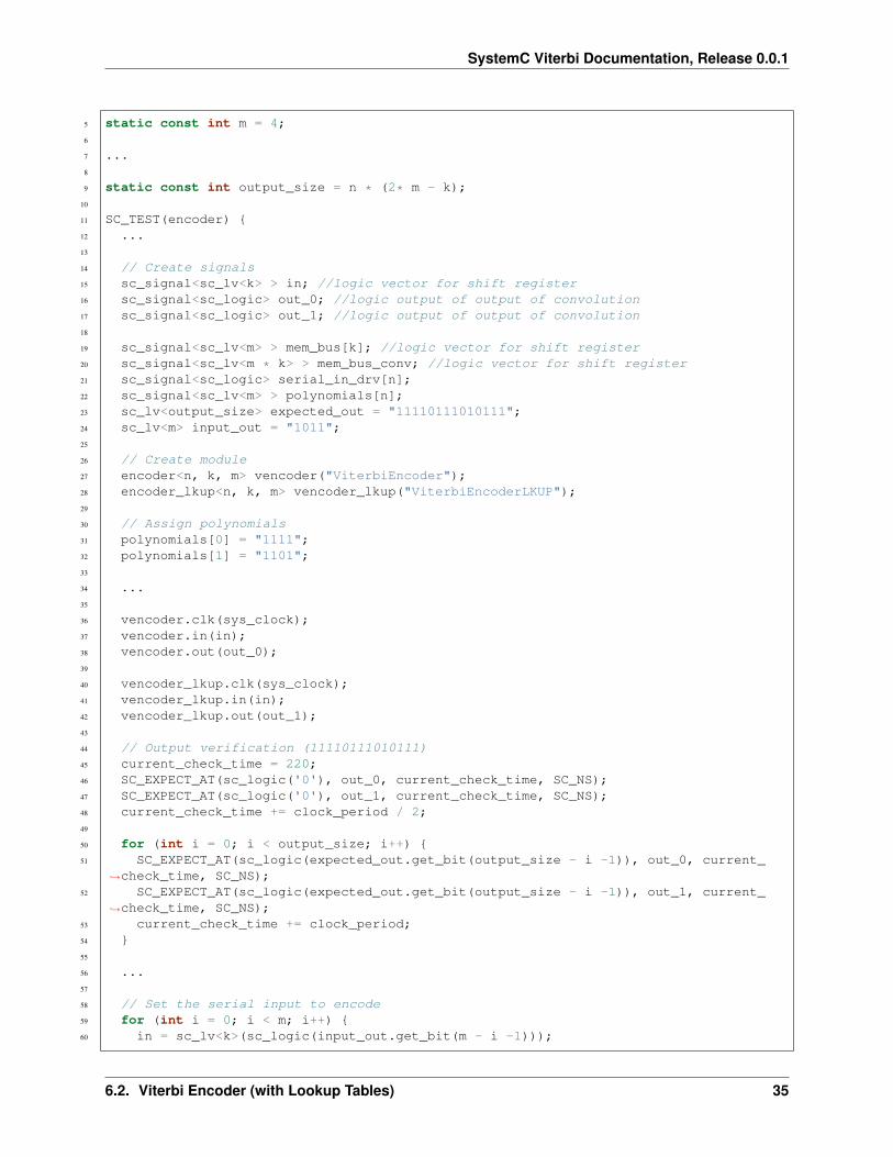
The code of the test case of the viterbi_encoder_lkup is shown below;
1 ...2
3 static const int n = 2;4 static const int k = 1;
6.1. Viterbi Encoder 29

SystemC Viterbi Documentation, Release 0.0.1
Fig. 6.2: Viterbi Encoder Circuit
5 static const int m = 4;6
7 ...8
9 static const int output_size = n * (2* m - k);10
11 SC_TEST(encoder) {12 ...13
14 // Create signals15 sc_signal<sc_lv<k> > in; //logic vector for shift register16 sc_signal<sc_logic> out_0; //logic output of output of convolution17 sc_signal<sc_logic> out_1; //logic output of output of convolution18
19 sc_signal<sc_lv<m> > mem_bus[k]; //logic vector for shift register20 sc_signal<sc_lv<m * k> > mem_bus_conv; //logic vector for shift register21 sc_signal<sc_logic> serial_in_drv[n];22 sc_signal<sc_lv<m> > polynomials[n];23 sc_lv<output_size> expected_out = "11110111010111";24 sc_lv<m> input_out = "1011";25
26 // Create module27 encoder<n, k, m> vencoder("ViterbiEncoder");28 encoder_lkup<n, k, m> vencoder_lkup("ViterbiEncoderLKUP");29
30 // Assign polynomials31 polynomials[0] = "1111";32 polynomials[1] = "1101";33
30 Chapter 6. Viterbi Encoder

SystemC Viterbi Documentation, Release 0.0.1
34 ...35
36 vencoder.clk(sys_clock);37 vencoder.in(in);38 vencoder.out(out_0);39
40 vencoder_lkup.clk(sys_clock);41 vencoder_lkup.in(in);42 vencoder_lkup.out(out_1);43
44 // Output verification (11110111010111)45 current_check_time = 220;46 SC_EXPECT_AT(sc_logic('0'), out_0, current_check_time, SC_NS);47 SC_EXPECT_AT(sc_logic('0'), out_1, current_check_time, SC_NS);48 current_check_time += clock_period / 2;49
50 for (int i = 0; i < output_size; i++) {51 SC_EXPECT_AT(sc_logic(expected_out.get_bit(output_size - i -1)), out_0, current_
→˓check_time, SC_NS);52 SC_EXPECT_AT(sc_logic(expected_out.get_bit(output_size - i -1)), out_1, current_
→˓check_time, SC_NS);53 current_check_time += clock_period;54 }55
56 ...57
58 // Set the serial input to encode59 for (int i = 0; i < m; i++) {60 in = sc_lv<k>(sc_logic(input_out.get_bit(m - i -1)));61 sc_start(2*clock_period, SC_NS);62 }63
64 in = "0";65 sc_start(200, SC_NS);66
67 }
Note:
• Both implementation of Viterbi encoder are being tested the same way.
• Both encoders have the same input.
• The input is 𝑏1011 and the expected encoded value 𝑏11110111010111
• The output is being verified with the SC_EXPECT_AT
Fig. 6.6 shows the result of the simulation.
Note:
• At 200𝑛𝑠 the input starts to be in encoded. Both encoders have the same input.
• Just 𝑜𝑢𝑡𝑝𝑢𝑡 cycles after the encoding starts.
• The encoded value’s MSb is transmitted first.
• Every in state has to be stable for 𝑜𝑢𝑡𝑝𝑢𝑡 cycles.
6.1. Viterbi Encoder 31

SystemC Viterbi Documentation, Release 0.0.1
Fig. 6.3: Encoder Simulation Wave Result
• out_0 and out_1 have the same baudrate as the sys_clock
• out_0 and out_1 present the same behavior as expected
• out_0 and out_1 are set back to sc_logic(‘0’) after encoding is done (430𝑛𝑠).
Viterbi Encoder (with Lookup Tables)
Class Diagram
The UML diagram of Fig. 6.4 shows the overview of the class.
Class Description
template<int output, int input, int memory>class encoder_lkup
Viterbi Encoder with lookup tables
sc_core::sc_in_clk clkInput clock
sc_in<sc_lv<input>> inParallel input to be encoded
sc_in<sc_lv<memory * input>> polynomials[output]Polynomials to convolve with
sc_out<sc_logic> outSerialized encoded output
sc_lv<memory * input> curr_stateCurrent State value holder
sc_lv<memory * input> next_state_lkp[lookup_size]Next state lookup table. This is filled in by create_states_lkup.
sc_lv<output> output_lkp[lookup_size]Output lookup table
uint div_counterClock divider counter
32 Chapter 6. Viterbi Encoder

SystemC Viterbi Documentation, Release 0.0.1
Fig. 6.4: Viterbi Encoder with Lookup Tables Class Diagram
6.2. Viterbi Encoder (with Lookup Tables) 33

SystemC Viterbi Documentation, Release 0.0.1
void prc_state_trasition(void)Transit from one state to the other depending on input and current state. Uses the lookup table to determinethe next step.
list sensitivityclk.pos()
void prc_update_output_lkup(void)Updates the output lookup table if any change occurs in the polynomials.
list sensitivitypolynomials
Note: next_state_lkp[lookup_size] and output_lkp[lookup_size] are filled using create_states_lkup and cre-ate_output_lkup respectively.
Structure
Fig. 6.5 shows the structure of the our Viterbi encoder implementation using lookup tables.
Fig. 6.5: Viterbi Encoder with Lookup Table Circuit
Simulation Results
The code of the test case of the viterbi_encoder_lkup is shown below;
1 ...2
3 static const int n = 2;4 static const int k = 1;
34 Chapter 6. Viterbi Encoder
SystemC Viterbi Documentation, Release 0.0.1
5 static const int m = 4;6
7 ...8
9 static const int output_size = n * (2* m - k);10
11 SC_TEST(encoder) {12 ...13
14 // Create signals15 sc_signal<sc_lv<k> > in; //logic vector for shift register16 sc_signal<sc_logic> out_0; //logic output of output of convolution17 sc_signal<sc_logic> out_1; //logic output of output of convolution18
19 sc_signal<sc_lv<m> > mem_bus[k]; //logic vector for shift register20 sc_signal<sc_lv<m * k> > mem_bus_conv; //logic vector for shift register21 sc_signal<sc_logic> serial_in_drv[n];22 sc_signal<sc_lv<m> > polynomials[n];23 sc_lv<output_size> expected_out = "11110111010111";24 sc_lv<m> input_out = "1011";25
26 // Create module27 encoder<n, k, m> vencoder("ViterbiEncoder");28 encoder_lkup<n, k, m> vencoder_lkup("ViterbiEncoderLKUP");29
30 // Assign polynomials31 polynomials[0] = "1111";32 polynomials[1] = "1101";33
34 ...35
36 vencoder.clk(sys_clock);37 vencoder.in(in);38 vencoder.out(out_0);39
40 vencoder_lkup.clk(sys_clock);41 vencoder_lkup.in(in);42 vencoder_lkup.out(out_1);43
44 // Output verification (11110111010111)45 current_check_time = 220;46 SC_EXPECT_AT(sc_logic('0'), out_0, current_check_time, SC_NS);47 SC_EXPECT_AT(sc_logic('0'), out_1, current_check_time, SC_NS);48 current_check_time += clock_period / 2;49
50 for (int i = 0; i < output_size; i++) {51 SC_EXPECT_AT(sc_logic(expected_out.get_bit(output_size - i -1)), out_0, current_
→˓check_time, SC_NS);52 SC_EXPECT_AT(sc_logic(expected_out.get_bit(output_size - i -1)), out_1, current_
→˓check_time, SC_NS);53 current_check_time += clock_period;54 }55
56 ...57
58 // Set the serial input to encode59 for (int i = 0; i < m; i++) {60 in = sc_lv<k>(sc_logic(input_out.get_bit(m - i -1)));
6.2. Viterbi Encoder (with Lookup Tables) 35

SystemC Viterbi Documentation, Release 0.0.1
61 sc_start(2*clock_period, SC_NS);62 }63
64 in = "0";65 sc_start(200, SC_NS);66
67 }
Note:
• Both implementation of Viterbi encoder are being tested the same way.
• Both encoders have the same input.
• The input is 𝑏1011 and the expected encoded value 𝑏11110111010111
• The output is being verified with the SC_EXPECT_AT
Fig. 6.6 shows the result of the simulation.
Fig. 6.6: Encoder Simulation Wave Result
Note:
• At 200𝑛𝑠 the input starts to be in encoded. Both encoders have the same input.
• Just 𝑜𝑢𝑡𝑝𝑢𝑡 cycles after the encoding starts.
• The encoded value’s MSb is transmitted first.
• Every in state has to be stable for 𝑜𝑢𝑡𝑝𝑢𝑡 cycles.
• out_0 and out_1 have the same baudrate as the sys_clock
• out_0 and out_1 present the same behavior as expected
• out_0 and out_1 are set back to sc_logic(‘0’) after encoding is done (430𝑛𝑠).
Convolution
Class Diagram
The UML diagram of Fig. 6.7 shows the overview of the class.
36 Chapter 6. Viterbi Encoder

SystemC Viterbi Documentation, Release 0.0.1
Fig. 6.7: Convolution Block Class Diagram
Class Description
template<int width>class convolution
Convolution block
sc_in<sc_lv<width>> inputParallel input to be convolved
sc_in<sc_lv<width>> polynomialPolynomials to convolve with
sc_out<sc_logic> yConvolved output
void prc_calculate_conv(void)Convolution Process. Logic and between input and polynomial and xor reduce the result.
list sensitivityinput
Structure
The structure of this module comprises an array of 𝑖𝑛𝑝𝑢𝑡 * 𝑚𝑒𝑚𝑜𝑟𝑦 and-gates to apply a bit-wise and between thepolynomials and the input port. After applying the bit-wise and a xor reduce of all bits have to be applied. This implied(𝑖𝑛𝑝𝑢𝑡 *𝑚𝑒𝑚𝑜𝑟𝑦)− 1 xor-gates applying a xor operation to every bit of the result of the bit-wise and the result of thexor gate of the previous 2 bits (for the first 2 bits the xor-gate is simply apply to both).
6.3. Convolution 37

SystemC Viterbi Documentation, Release 0.0.1
Simulation Results
The code of the test case of the convolution is shown below;
1 ...2
3 static const int reg_width = 3;4
5 ...6
7 SC_TEST(convolution) {8
9 // create channels10 sc_signal<sc_lv<reg_width> > shift_reg; //logic vector for shift register11 sc_signal<sc_lv<reg_width> > generator_polynomial; //logic vector for shift register12 sc_signal<sc_logic> conv_output; //logic output of output of convolution13
14 // create module15 convolution<reg_width> convolution("Convolution");16
17 ...18
19 generator_polynomial = "101";20
21 // start simulation22 shift_reg = "100";23 sc_start(100, SC_NS);24
25 shift_reg = "110";26 sc_start(100, SC_NS);27
28 }
Note:
• generator_polynomial is constant with value 𝑏101
• shift_reg starts with value 𝑏100 and changes to 𝑏110 at 100𝑛𝑠.
Fig. 6.8 shows the result of the simulation.
Fig. 6.8: Convolution Simulation Wave Result
Note:
• Since the convolution is purely combinational no clock is needed.
38 Chapter 6. Viterbi Encoder

CHAPTER 7
Viterbi Decoder
This section presents our implementation of the Viterbi decoder.
Viterbi Decoder
Class Diagram
The UML diagram of Fig. 7.1 shows the overview of the class.
Class Description
template<int output, int input, int memory>class decoder_viterbi
Viterbi Decoder
sc_core::sc_in_clk clkInput clock
sc_in<sc_lv<input>> inSerial input to be decoded
sc_in_clk triggerDecoding Trigger
sc_in<sc_lv<memory * input>> polynomials[output]Polynomials used for encoding
sc_out<sc_logic> outDecoded serial output
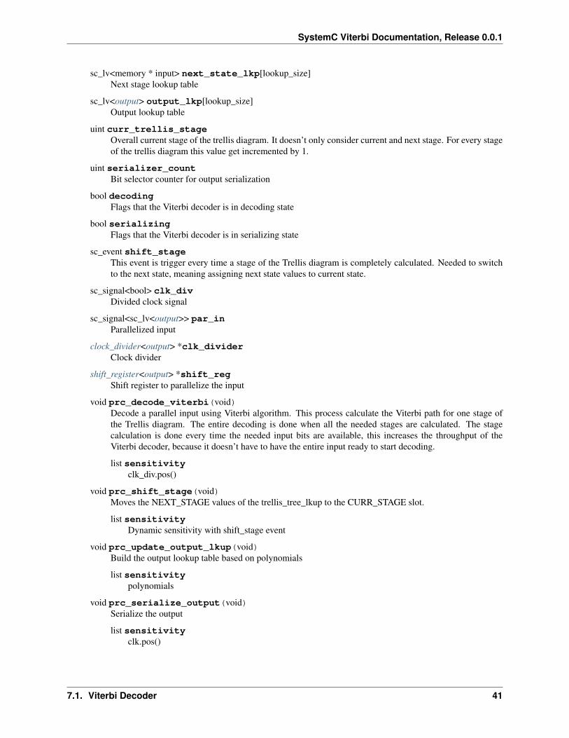
viterbi_path_s<output_buffer_bit_size> trellis_tree_lkup[MAX_STAGES][states_num]Trellis diagram lookup table. It only stores current stage and next stage. These 2 stages are the only onesneeded at every calculation point in time.
39

SystemC Viterbi Documentation, Release 0.0.1
Fig. 7.1: Viterbi Decoder Class Diagram
40 Chapter 7. Viterbi Decoder
SystemC Viterbi Documentation, Release 0.0.1
sc_lv<memory * input> next_state_lkp[lookup_size]Next stage lookup table
sc_lv<output> output_lkp[lookup_size]Output lookup table
uint curr_trellis_stageOverall current stage of the trellis diagram. It doesn’t only consider current and next stage. For every stageof the trellis diagram this value get incremented by 1.
uint serializer_countBit selector counter for output serialization
bool decodingFlags that the Viterbi decoder is in decoding state
bool serializingFlags that the Viterbi decoder is in serializing state
sc_event shift_stageThis event is trigger every time a stage of the Trellis diagram is completely calculated. Needed to switchto the next state, meaning assigning next state values to current state.
sc_signal<bool> clk_divDivided clock signal
sc_signal<sc_lv<output>> par_inParallelized input
clock_divider<output> *clk_dividerClock divider
shift_register<output> *shift_regShift register to parallelize the input
void prc_decode_viterbi(void)Decode a parallel input using Viterbi algorithm. This process calculate the Viterbi path for one stage ofthe Trellis diagram. The entire decoding is done when all the needed stages are calculated. The stagecalculation is done every time the needed input bits are available, this increases the throughput of theViterbi decoder, because it doesn’t have to have the entire input ready to start decoding.
list sensitivityclk_div.pos()
void prc_shift_stage(void)Moves the NEXT_STAGE values of the trellis_tree_lkup to the CURR_STAGE slot.
list sensitivityDynamic sensitivity with shift_stage event
void prc_update_output_lkup(void)Build the output lookup table based on polynomials
list sensitivitypolynomials
void prc_serialize_output(void)Serialize the output
list sensitivityclk.pos()
7.1. Viterbi Decoder 41

SystemC Viterbi Documentation, Release 0.0.1
void prc_decode_catch_trigger(void)Catch the trigger for decoding. Initialize all needed structures for running the Viterbi decoding algorithm.Flags the decoding state after initialization.
list sensitivitytrigger.pos()
void prc_decode_start_serializing(void)Catches the trigger for starting serialization. Flags serializing state and unflags the decoding state.
list sensitivitytrigger.neg()
uint get_metrics(uint val_0, uint val_1)Calculate the metrics between two values.
Parameters
• unit val_0 – First value
• unit val_1 – Second value
Returns Metric value
Simulation Results
The code of the test case of the viterbi_decoder is shown below;
1 static const int n = 2;2 static const int k = 1;3 static const int m = 4;4
5 ...6
7 static const int output_size = n * (2* m - k);8
9 SC_TEST(decoder) {10
11 // Create signals12 sc_signal<sc_logic> in;13 sc_signal<sc_logic> out;14 sc_lv<4> expected_out;15 sc_signal<sc_lv<m> > polynomials[n];16 sc_lv<output_size> in_bus;17 sc_signal<bool> trigger;18 uint current_check_time;19
20
21 expected_out = "1011";22
23 // Create module24 decoder_viterbi<n, k, m, out_buff> vdecoder("ViterbiDecoder");25
26 // Assign polynomials27 polynomials[0] = "1111";28 polynomials[1] = "1101";29
30 ...31
32 for (int i = 0; i < n; i++) {
42 Chapter 7. Viterbi Decoder

SystemC Viterbi Documentation, Release 0.0.1
33 ...34 vdecoder.polynomials[i](polynomials[i]);35 }36
37 vdecoder.clk(sys_clock);38 vdecoder.in(in);39 vdecoder.out(out);40 vdecoder.trigger(trigger);41
42 ...43
44 // Output verification (1011)45 current_check_time = 312;46 SC_EXPECT_AT(sc_logic('0'), out, current_check_time, SC_NS);47 current_check_time += clock_period;48 for (int i = 0; i < m; i++) {49 SC_EXPECT_AT(sc_logic(expected_out.get_bit(m - i -1)), out, current_check_time,
→˓SC_NS);50 current_check_time += clock_period;51 }52
53 current_check_time = 1010;54 SC_EXPECT_AT(sc_logic('0'), out, current_check_time, SC_NS);55 current_check_time += clock_period;56 for (int i = 0; i < m; i++) {57 SC_EXPECT_AT(sc_logic(expected_out.get_bit(m - i -1)), out, current_check_time,
→˓SC_NS);58 current_check_time += clock_period;59 }60
61
62
63 trigger = false;64 in = sc_logic('0');65
66 // Trigger and receive the correct data67 sc_start(50, SC_NS);68 trigger = true;69
70 in_bus = "11110111010111";71
72 for (int i = 0; i < output_size; i++) {73 in = in_bus[output_size - i - 1];74 sc_start(clock_period, SC_NS);75 }76
77 in = sc_logic('0');78
79 sc_start(50, SC_NS);80 trigger = false;81
82
83 sc_start(490, SC_NS);84
85 // Trigger and receive the data with errors86 in_bus = "01100111010110";87 trigger = true;88 for (int i = 0; i < output_size; i++) {
7.1. Viterbi Decoder 43

SystemC Viterbi Documentation, Release 0.0.1
89 in = in_bus[output_size - i - 1];90 sc_start(clock_period, SC_NS);91 }92 in = sc_logic('0');93
94 sc_start(5, SC_NS);95 trigger = false;96
97 sc_start(500, SC_NS);98
99 }
Note:
• At 50𝑛𝑠 the correct data starts coming in.
• At 815𝑛𝑠 the data with 3 inverted bits starts coming in.
Fig. 7.2 shows the result of the simulation for the correct data being received and Fig. 7.3 shows the results of thesimulation for the data with 3 inverted bits.
Fig. 7.2: Decoder Simulation Wave Result
Note:
• At 312.5𝑛𝑠 the decoding of the correct data starts going out.
• The decoding of the correct data is 𝑏1011.
• At 1017.5𝑛𝑠 the decoding of the data with errors starts going out.
• The decoding of the data with 3 inverted bits is 𝑏1011.
• The decoding is successful even with errors.
44 Chapter 7. Viterbi Decoder

SystemC Viterbi Documentation, Release 0.0.1
Fig. 7.3: Decoder Simulation With Errors Wave Result
• The metric of best path (with higher metric) passing through every of the 8 states can be seen in the trellis.state(0-7).metric[31:0].
• The possible output of best path (with higher metric) passing through every of the 8 states can be seen in thetrellis.state(0-7).output[15:0]
7.1. Viterbi Decoder 45

SystemC Viterbi Documentation, Release 0.0.1
46 Chapter 7. Viterbi Decoder

Index
Cclock_divider (C++ class), 17clock_divider::clk_in (C++ member), 17clock_divider::clk_out (C++ member), 17clock_divider::divider_counter (C++ member), 17clock_divider::prc_clock_divider (C++ function), 17clock_divider::prc_clock_divider::sensitivity (C++ mem-
ber), 17convolution (C++ class), 37convolution::input (C++ member), 37convolution::polynomial (C++ member), 37convolution::prc_calculate_conv (C++ function), 37convolution::prc_calculate_conv::sensitivity (C++ mem-
ber), 37convolution::y (C++ member), 37create_output_lkup (C++ function), 14create_states_lkup (C++ function), 14
Ddecoder_viterbi (C++ class), 39decoder_viterbi::clk (C++ member), 39decoder_viterbi::clk_div (C++ member), 41decoder_viterbi::clk_divider (C++ member), 41decoder_viterbi::curr_trellis_stage (C++ member), 41decoder_viterbi::decoding (C++ member), 41decoder_viterbi::get_metrics (C++ function), 42decoder_viterbi::in (C++ member), 39decoder_viterbi::next_state_lkp (C++ member), 39decoder_viterbi::out (C++ member), 39decoder_viterbi::output_lkp (C++ member), 41decoder_viterbi::par_in (C++ member), 41decoder_viterbi::polynomials (C++ member), 39decoder_viterbi::prc_decode_catch_trigger (C++ func-
tion), 42decoder_viterbi::prc_decode_catch_trigger::sensitivity
(C++ member), 42decoder_viterbi::prc_decode_start_serializing (C++ func-
tion), 42
decoder_viterbi::prc_decode_start_serializing::sensitivity(C++ member), 42
decoder_viterbi::prc_decode_viterbi (C++ function), 41decoder_viterbi::prc_decode_viterbi::sensitivity (C++
member), 41decoder_viterbi::prc_serialize_output (C++ function), 41decoder_viterbi::prc_serialize_output::sensitivity (C++
member), 41decoder_viterbi::prc_shift_stage (C++ function), 41decoder_viterbi::prc_shift_stage::sensitivity (C++ mem-
ber), 41decoder_viterbi::prc_update_output_lkup (C++ func-
tion), 41decoder_viterbi::prc_update_output_lkup::sensitivity
(C++ member), 41decoder_viterbi::serializer_count (C++ member), 41decoder_viterbi::serializing (C++ member), 41decoder_viterbi::shift_reg (C++ member), 41decoder_viterbi::shift_stage (C++ member), 41decoder_viterbi::trellis_tree_lkup (C++ member), 39decoder_viterbi::trigger (C++ member), 39
Eencoder (C++ class), 27encoder::clk (C++ member), 27encoder::clk_div (C++ member), 29encoder::clk_divider (C++ member), 29encoder::conv_block (C++ member), 29encoder::conv_outs (C++ member), 29encoder::conv_par_bus (C++ member), 29encoder::data_in_drv (C++ member), 29encoder::in (C++ member), 27encoder::mem_bus (C++ member), 29encoder::mem_bus_conv (C++ member), 27encoder::out (C++ member), 27encoder::polynomials (C++ member), 27encoder::prc_arrange_memory_bus (C++ function), 29encoder::prc_arrange_memory_bus::sensitivity (C++
member), 29encoder::prc_split_input (C++ function), 29
47

SystemC Viterbi Documentation, Release 0.0.1
encoder::prc_split_input::sensitivity (C++ member), 29encoder::prc_update_conv_par_bus (C++ function), 29encoder::prc_update_conv_par_bus::sensitivity (C++
member), 29encoder::register_bank (C++ member), 29encoder::serial (C++ member), 29encoder_lkup (C++ class), 32encoder_lkup::clk (C++ member), 32encoder_lkup::curr_state (C++ member), 32encoder_lkup::div_counter (C++ member), 32encoder_lkup::in (C++ member), 32encoder_lkup::next_state_lkp (C++ member), 32encoder_lkup::out (C++ member), 32encoder_lkup::output_lkp (C++ member), 32encoder_lkup::polynomials (C++ member), 32encoder_lkup::prc_state_trasition (C++ function), 32encoder_lkup::prc_state_trasition::sensitivity (C++ mem-
ber), 34encoder_lkup::prc_update_output_lkup (C++ function),
34encoder_lkup::prc_update_output_lkup::sensitivity (C++
member), 34
SSC_EXPECT_AFTER (C macro), 12SC_EXPECT_AT (C macro), 10SC_SETUP (C macro), 12SC_SIGNAL_SET (C macro), 12SC_STRACE (C macro), 10SC_TEARDOWN (C macro), 12SC_TEST (C macro), 10SC_TRACE (C macro), 10serializer (C++ class), 19serializer::clk_in (C++ member), 19serializer::output_selector (C++ member), 20serializer::par_in (C++ member), 19serializer::prc_serializer (C++ function), 20serializer::prc_serializer::sensitivity (C++ member), 20serializer::prc_serializer_counter_reset (C++ function),
20serializer::prc_serializer_counter_reset::sensitivity (C++
member), 20serializer::prc_serializer_counter_update (C++ function),
20serializer::prc_serializer_counter_update::sensitivity
(C++ member), 20serializer::ser_out (C++ member), 19serializer::ser_trig (C++ member), 19shift_register (C++ class), 22shift_register::clk (C++ member), 22shift_register::data_in (C++ member), 22shift_register::prc_shift_register (C++ function), 23shift_register::prc_shift_register::sensitivity (C++ mem-
ber), 23
shift_register::q (C++ member), 22shift_register::q_state (C++ member), 23
Vviterbi_path_s (C++ class), 13viterbi_path_s::is_alive (C++ member), 14viterbi_path_s::metric_value (C++ member), 14viterbi_path_s::operator= (C++ function), 14viterbi_path_s::operator== (C++ function), 14viterbi_path_s::path_output (C++ member), 14viterbi_path_s::path_size (C++ member), 14viterbi_path_s::sc_trace (C++ function), 14
48 Index