task 2.5 - coaltech
TRANSCRIPT

1
COALTECH 2020
Task 2.5.2 Economic and safe extraction of pillars and
associated reserves using underground mining
methods
by
Conri Moolman & Ismet Canbulat
September 2003
Copyright COALTECH 2020
This document is for the use of COALTECH 2020 only, and may not be transmitted to any other
party, in whole or in part, in any form without the written permission of COALTECH.

2
Executive summary
The project is aimed at identifying and evaluating potential underground mining methods
to ensure the economic and safe extraction of coal pillars and associated reserves in the
Witbank and Highveld Coalfields.
Through the research it was established that approximately 1.1 billion tons of potentially
mineable coal were left underground in the form of coal pillars during the period 1970 to
1997. This number is growing by approximately 110 million tons per annum as a result of
the current bord and pillar mining practices. Vast potential exists for the increased
utilization of the coal resource through the application of pillar extraction mining methods,
especially at greater depth. This holds large economic value as well, despite increased
environmental management costs. The development of new and improved pillar extraction
mining methods at shallower depth also holds large potential.
The project incorporates a literature survey of previous work done and various site visits
with the objective of identifying potentially suitable mining methods as well as limitations,
shortcomings and factors constraining these methods. These include environmental
impacts, strata control, ventilation, health and safety aspects, etc., both from the history
and current mining practices points of view. In addition it includes some international
perspectives on high extraction mining methods.
High extraction mining methods are generally used where it has become necessary to
extend the life of the mine and are not practiced simply to increase extraction ratios or
production. At present, only Tavistock and Tweefontein Collieries are practicing pillar
extraction in the Witbank Coalfield, with some Ingwe mines doing partial extraction. Sasol
Coal however is practicing various methods of pillar extraction extensively in the Secunda
area. Pillars with a nominal safety factor of about 1.8 and higher (using the Salomon and
Munro formula) can be successfully extracted.
Extensive site visits highlighted that the operating personnel practising pillar extraction
considered discipline and pillar safety factors to be the main areas of concern, more so
than the age of the pillars. It was also noted that extracting older pillars was generally
more difficult than extracting new pillars.
The primary factors influencing the design and extraction of coal pillars are:
• Pillar conditions
3
• Roof and floor conditions
• Geological and geotechnical conditions
• Age of pillars
• Surface constraints
• Environmental issues
• Coal quality
• Economic considerations
Although it was generally agreed that there is a greater risk associated with pillar-
extraction mining than normal bord and pillar development, there was no definite evidence
that the fatality and/or injury rate for pillar extraction done with continuous miners is higher
than for bord and pillar mining. In fact, it appears that it may even be lower. Furthermore,
pillar extraction is considered safe up to heights of 3.5 m, after which pillar splitting,
robbing or partial pillar-extraction methods are used.
Nevid pillar extraction method has been identified as one of the potential methods to be
used in pillar extraction. However, this method has usually been applied at greater depths
(>150 m) by Sasol. As part of this study a detailed investigation of the application of Nevid
method at shallow depths was conducted. The dimensions of the cutting widths and snook
sizes were established.
The study into the effect of panel widths showed that the panel width is one of the most
important parameters in determining the load and the safety factors of pillar in the active
mining zone. It is suggested that the panel widths should be reduced in order to reduce
the load acting on the pillars.
In addition, abutment angle, which also determines the load acting on the pillars in the
active mining zone, was found to be an important parameter in pillar extraction. Detailed
calculations of the safety factors and the load acting on the pillars in the active mining
zones were presented.
Five design flow sheets for rock engineering, environment assessment, mining, coal
beneficiation, and financial evaluation have been developed for the decision making
process. However, because so many parameters used in different flow sheets, the design
flow sheets were rationalized into simple flow sheets for decision making process in pillar
extraction.

4
Fault tree for stability risk evaluation
Regional instability Local
instability Multi-seam instability
Stress hazards
Probability that pillar recovery cannot be done
Subsidence hazards
Strata caving hazards
Pillars are unstable
Roof is unstable
Floor instabiltiy
Other seam not stooped
Cannot mine over old workings
Cannot mine under old workings
Other seam stooped
Regional geology hazards
Field stresses Adjacent mining
Dolerite sills Sandstone beams Depth/span ratio
Surface usage Subsidence mode Hydrology
Factor of safety Pillar age Pillar scaling Pillar jointing
Age of workings Roof collapse Jointing in roof Roof composition
Floor composition Floor undulations Presence of water Age of workings
Major lineaments Faults Intrusions
Parting composition Parting thickness Parting jointing
Parting instability
Other seam pillar instability
Other workings age Other seam FOS Superposition Barriers Remnants
Seam separation Goaf consolidation Remnant pillars
Seam separation Goaf consolidation Remnant pillars Groundwater
or
or
or
or
or
or

5
The project proposes a rock engineering risk rating system to evaluate all potential pillar
extraction panels for possible selection as future pillar extraction panels on a pre-
feasibility level (see page Figure overleaf).
This pre-feasibility study was incorporated into a spreadsheet and available to
COALTECH 2020 participants. This is then followed by a full feasibility study for final
selection (below Figure).
Start
Continue
Select mining method
Design and costing
Financial evaluation- royalties and taxes- cash flow- sensitivity- NPV, IRR, Cost benefit ratio
Determine constraints
M ining Constraints- panel conditions- dilution- mining equipment- access- ventilation- infrastructure- safety- regulations
Rock Eng Constraints- subsidence- pillar stability- roof stabil ity- extraction ratio- barriers- seam interaction- safety- regulations
Environmental Constraints- subsidence effects- water quality- groundwater flow- underground fires- land alienation- safety- regulations
Beneficiation Constraints- plant l imitations- coal quality- market requirements- plant capabilities- discard handling- safety- regulations
Mining design- access and opening up - extraction method - production rate- equipment lis t- consumables list- staffing- ventilation- infrastructure- cost of opening up- capital cost estimate- mining cost estimate
Rock Eng. design- p illar design- b arrier pil lar design- subsidence assessment- support design- extraction sequence- support sequence- equipment costing- support costing
Environmental design- subsidence effects- subsidence rehabilitation- hydrological analysis- groundwater rehabilitation- coal fire assessment- monitoring systems- capital costs- operating costs
Beneficiation design- plant evaluation- discard handing- tail ings treatment- staffing- infrastructure- maintenance- plant design- operating costs- capital costs
Calculate mineable reserve
Flowchart for feasibility study

6
Four basic approaches to the utilisation of coal left behind in pillars are proposed in the
final selection of the most suitable mining method. The selected potential pillar extraction
panels are finally evaluated in a decision support system based on the Analytical
Hierarchy Process to select the most suitable mining approach. Various detailed mining
methods are included in the report for the selection of a specific method or to form the
basis for the development of a new method.
The outline of the AHP process may be summarized as shown below. The goal of finding
the best method is set. Below the goal, the criteria are subdivided into disciplines. The
relative weighting of each criterion is determined using pairwise comparisons. Finally the
alternative methods are evaluated, using pairwise comparisons against each of the
criteria. The outcomes are manipulated mathematically to provide the best solution.
The method has been programmed into a spreadsheet, so that users do not need to carry
out the calculations themselves. The spreadsheet program is specifically designed to
evaluate the problem of mining method selection, using the criteria listed above.
Outline of analytical hierarchy process for selecting best method
GoalBest mining method
Mining BeneficiationEnvironmentalRock mechanics
•Cost•Safety•Recovery•Splitting direction•Training & experience•Breakerlines•Adaptable to conditions•Dilution•Equipment adequate•Regulations•Capital requirments
•Surface subsidence•Pillar stability•Snook stability•Snook failure•System stiffness•Goaf control•Caving of upper strata•Middling stability•Adjacent seam workings•Roof strength
•Surface subsidence•Groundwater•Closure issues
•Dilution•Size distribution
Full pillar recovery Checkerboard Pillar splitting Pillar quartering

7
From the literature survey and the workshops held, serious shortcomings in the mining
methods currently available and their applicability for the mining of thin seams (less than
1.5 m) were identified. This area has however been targeted for future research and the
report will primarily focus on the medium to high seam range.
In conclusions it is strongly recommended that the methods and guidelines given in this
project should be applied in an actual pillar extraction project in order to determine the
applicability of them.

8
Project team members
The project team members responsible for the project are as follows:
Gavin Lind, University of the Witwatersrand
P van Vuuren – University of Pretoria
Prof. H R Phillips, University of the Witwatersrand
D Hardman, University of the Witwatersrand
Dr N van der Merwe, CSIR Division of Mining Technology
G S Esterhuizen, Steffen, Robertson and Kirsten, USA

9
Table of contents
Executive summary ............................................................................................... 1
Project team members ......................................................................................... 8
Table of contents .................................................................................................... 9
List of Figures .........................................................................................................13
List of Tables ...........................................................................................................16
1.0 Introduction ...................................................................................................17
1.1 Importance of secondary extraction .............................................................17
1.2 Increased extraction ......................................................................................19
1.3 Financial value of increased extraction .......................................................23
1.3.1 Production scenario’s ............................................................................23 1.3.2 Pillar extraction and ground water inflow .............................................24 1.3.3 Low safety factor mining followed by ashfilling. ..................................25 1.3.4 Financial evaluation. ..............................................................................25
1.4 Conclusion ......................................................................................................26
2.0 Research methodology ...........................................................................28
3.0 Literature survey ........................................................................................29
3.1 Introduction .....................................................................................................29
3.2 Mining methods ..............................................................................................29
3.2.1 Decision-making considerations for pillar extraction ..........................30 3.2.2 Planning for pillar extraction ..................................................................30 3.2.3 History of pillar extraction ......................................................................32
3.3 International experience ................................................................................33
3.3.1 The Wongawilli system ..........................................................................33 3.3.2 The Munmorrah system .........................................................................34 3.3.3 The Old Ben method ..............................................................................35 3.3.4 The Christmas tree method ...................................................................36 3.3.5 The outside lift method ..........................................................................37 3.3.6 Summary of findings of pillar extraction in New South Wales ...........38
3.4 South African experience ..............................................................................41
3.4.1 The open-end system ............................................................................41 3.4.2 The pocket-and-fender system .............................................................41 3.4.3 Usutu method .........................................................................................42 3.4.4 Rib pillar extraction in South Africa ......................................................44 3.4.5 Advantages of the rib-pillar system ......................................................46 3.4.6 Disadvantages of the rib-pillar system .................................................47

10
3.5 Factors constraining pillar extraction ...........................................................47
3.5.1 Ventilation ...............................................................................................47 3.5.2 Spontaneous combustion ......................................................................48 3.5.3 Rock engineering aspects .....................................................................49
3.5.3.1 Roof support ...................................................................................49 3.5.3.2 Pillar design.....................................................................................50 3.5.3.3 Squat pillar formula ........................................................................55 3.5.3.4 Effect of pillar geometry .................................................................56 3.5.3.5 Strata control ...................................................................................58 3.5.3.6 Surface subsidence ........................................................................59 3.5.3.7 Geology ...........................................................................................60 3.5.3.8 Design of suitable areas ................................................................60
3.5.4 Safety ......................................................................................................63
3.6 Conclusions ....................................................................................................67
4.0 Site visits ........................................................................................................68
4.1 Background to site visits ...............................................................................68
4.1.1 Introduction .............................................................................................68 4.1.2 Effect of the safety factor on accidents ................................................68 4.1.3 Condition of pillars in pillar-extraction sections ...................................69
4.2 List of sites visited ..........................................................................................70
4.3 Purpose of site visits ......................................................................................71
4.4 Conclusions from site visits ..........................................................................72
5.0 Review of current mining practices ..................................................75
5.1 Introduction .....................................................................................................75
5.2 Range of geometrical and geological settings ............................................76
5.3 Geology and support effectiveness ..............................................................77
5.4 Surface and underground environmental concerns ...................................77
5.5 Variation in coal quality and size ..................................................................78
5.6 Machine efficiency and machine modifications ...........................................78
5.7 Section safety .................................................................................................79
5.8 Costs ...............................................................................................................79
5.9 Method of pillar removal ................................................................................80
5.9.1 Small to medium pillars (angled cut method) ......................................81 5.9.2 Medium to large pillars (split and fender method) ...............................85 5.9.3 Medium to large pillars (Nevid method) ...............................................89 5.9.4 Conclusions ............................................................................................95
6.0 Application of “Nevid” pillar extraction method at shallow depth ............................................................................................................................97
6.1 Introduction .....................................................................................................97

11
6.2 Methodology ...................................................................................................97
6.3 Results .......................................................................................................... 101
7.0 Technical factors of constraint ......................................................... 102
7.1 Introduction ................................................................................................... 102
7.2 Critical factors in pillar extraction ............................................................... 102
7.2.1 Controllable parameters ...................................................................... 103 7.2.2 Uncontrollable parameters .................................................................. 110
7.3 Conclusions .................................................................................................. 117
8.0 Effect of panel geometry in pillar extraction .............................. 120
8.1 Introduction ................................................................................................... 120
8.2 LAMODEL .................................................................................................... 120
8.3 Model description ......................................................................................... 121
8.4 Material properties ....................................................................................... 124
8.5 Results .......................................................................................................... 125
8.5.1 Effect of leaving centre pillars as barriers .......................................... 125 8.5.2 The safety factor of the face-pillars .................................................... 127 8.5.3 Abutment stresses ............................................................................... 128 8.5.4 Effect of backfilling ............................................................................... 129
8.6 Conclusions .................................................................................................. 131
9.0 Surcharge load in pillar extraction .................................................. 133
9.1 Introduction ................................................................................................... 133
9.2 Calculation of surcharge load in pillar extraction ...................................... 133
10.0 Mining risk decision methodology .............................................. 137
10.1 Flow sheets for risk decision methodology ............................................... 137
10.2 Overall flow sheet for decision process ..................................................... 144
10.3 Detail of pre-feasibility risk assessment .................................................... 145
10.3.1 Objectives in developing risk assessment procedure ...................... 145 10.3.2 Causes of instability ............................................................................. 145 10.3.3 Risk rating value ................................................................................... 146 10.3.4 Development of spreadsheet .............................................................. 148 10.3.5 Typical results ....................................................................................... 149 10.3.6 Requirement further input and refinement ......................................... 151
10.4 Detailed feasibility study .............................................................................. 152
11.0 Mining method decision methodology ...................................... 155
11.1 Introduction ................................................................................................... 155
11.2 Differences between four selected mining methods ................................ 155

12
11.3 Requirements for successful application of methods ............................... 160
11.4 Checklist of requirements against panel constraints ................................ 161
11.5 Decision support system to select best mining method ........................... 164
11.6 Outline of decision process ......................................................................... 165
11.7 Example of application of AHP spreadsheet to evaluate suitability of mining methods ....................................................................................................... 166
12.0 Conclusions and recommendations ........................................... 172
13.0 References ............................................................................................... 177
Appendix 1: Comparison of Geometry and Resources .................... 183
Appendix 2: Geology and support efficiency ........................................ 184
Appendix 3: Miscellaneous ............................................................................. 186
Appendix 4: Example of checklist data collection form ................... 188
Appendix 5: Tables A1 to A7 .......................................................................... 197
Appendix 6: Review of underground pillar extraction mining methods in New South Wales ........................................................................ 206

13
List of Figures
Figure 1–1 Average dimensions of underground bord-and-pillar workings in South
African collieries (after Madden et al., 1995) ........................................................18
Figure 1–2 Estimated underground bord-and-pillar coal production for the period 1970
to 1999 .................................................................................................................19
Figure 1–3 Percentage extraction ratios for various mining methods ..........................22
Figure 3–1 Typical plan view of the Wongawilli system (after Skybey, 1982) ..............34
Figure 3–2 The Munmorrah mining system (after Beukes, 1989) ................................35
Figure 3–3 The Old Ben mining method (after Beukes, 1989) ....................................36
Figure 3–4 The Christmas tree extraction method. A, lifts 1-2A. B, lifts 1-8A. C, lifts
push; pushout removal units 1 and 2 in tandem. D, lifts 1-push; pushout removal
with units 1 and 2 staggered (after Chase et al., 1997) .........................................37
Figure 3–5 Outside lift method. A, lifts 1-6; B, lifts 1-7A; C, lifts 1-push (after Chase et
al., 1997) ..............................................................................................................38
Figure 3–6 Usutu pillar extraction sequence (After Beukes, 1989) ..............................43
Figure 3–7 Usutu pillar extraction method and support (After Beukes, 1989) ..............44
Figure 3–8 Rib-pillar mining method layout (after Beukes, 1989) ................................46
Figure 3–9 The four loading conditions that can be evaluated using ARMPS (after
Mark and Chase, 1999) ........................................................................................62
Figure 3–10 Relative distribution of fatal falls of ground for different mining methods
(period 1970 to 1988) ...........................................................................................65
Figure 3–11 Relative distribution of fatal falls of ground for different locations in bord-
and-pillar workings (period 1970 to 1988) .............................................................66
Figure 3–12 Relative distribution of fatal falls of ground for different locations in stooping
sections (1970 to 1988) ........................................................................................66
Figure 5–1 (a) Extraction of medium to large pillars with split and fender method -
mining sequence and ventilation layout with half bleeder road (b) Extraction of
small pillars with angled cut method - mining sequence and ventilation layout with
no bleeder road ....................................................................................................84
Figure 5–2 (a) Extraction of small pillars with angled cuts - cutting sequence (b)
Extraction of medium to large pillars with split and fender method - cutting
sequence .............................................................................................................88
Figure 5–3 Nevid – pillar extraction cutting sequence .................................................93
Figure 5–4 Nevid ventilation layout .............................................................................94
Figure 5–5 Nevid stooping cycle .................................................................................95

14
Figure 6–1 Controlling dimensions and cut sequence .................................................98
Figure 6–2 Geometry of Nevid method ..................................................................... 100
Figure 7–1 Two caving mechanisms as identified by Hill, 1994 ................................ 116
Figure 7–2 The critical factors in the design of pillar extraction ................................. 119
Figure 8–1 Model 1, 3-Rows mined, 1-Row left as barrier ........................................ 122
Figure 8–2 Model 2, 2-Rows mined, 1-Row left as barrier ........................................ 122
Figure 8–3 Model 3, 3-Rows mined, 2-Row left as barrier ........................................ 123
Figure 8–4 Model 4, 2-Rows mined, 2-Row left as barrier ........................................ 123
Figure 8–5 Model 5, All rows taken, common pillar extraction method ...................... 124
Figure 8–6 Effect of leaving artificial barrier pillars in the centre of the panel ............ 125
Figure 8–7 Comparison between the Model 1 and 5 with respect to stress on face-
pillars ............................................................................................................... 126
Figure 8–8 The percentage difference between Model 1 and 5 ................................ 127
Figure 8–9 The safety factor of face-pillars ............................................................... 128
Figure 8–10 The stresses acting on the artificial barrier pillars as the mining takes place
............................................................................................................... 129
Figure 8–11 Backfill material curve used in the models .............................................. 130
Figure 9–1 Surcharge load due to overhang in pillar extraction ................................ 133
Figure 9–2 Effect of abutment angle on pillar safety factor ....................................... 135
Figure 10–1 Flow sheet for rock engineering design ................................................... 138
Figure 10–2 Evaluation of environmental factors for pillar extraction .......................... 139
Figure 10–3 Evaluation of mining factors for pillar extraction ...................................... 140
Figure 10–4 Evaluation of coal beneficiation for pillar extraction ................................. 141
Figure 10–5 Financial evaluation for pillar extraction .................................................. 143
Figure 10–6 Fault tree for stability risk evaluation ....................................................... 147
Figure 10–7 Probability histogram –extraction of 20 year old pillars in a single Seam
setting ........................................................................................................... 150
Figure 10–8 Probability histogram –extraction of 20 year old pillars in multi-Seam
conditions ........................................................................................................... 151
Figure 10–9 Overall flowchart of decision process to proceed with pillar recovery ...... 152
Figure 10–10 Flowchart for feasibility study .............................................................. 154
Figure 11–1 Outline of analytical hierarchy process for selecting best method ........... 165
Figure 11–2 Relative importance of criteria for hypothetical Panel A .......................... 167
Figure 11–3 Relative importance of operational issues for hypothetical panel A ......... 167
Figure 11–4 Relative importance of stability considerations for hypothetical panel A .. 168
Figure 11–5 Relative importance of environmental and beneficiation issues for
hypothetical Panel A ........................................................................................... 168

15
Figure 11–6 Final priorities of mining methods for hypothetical Panel A ..................... 169
Figure 11–7 Relative importance of criteria for hypothetical Panel B .......................... 170
Figure 11–8 Priorities of mining methods for hypothetical Panel B ............................. 170
Figure 11–9 Weighting of methods by main criteria .................................................... 171
Figure 0–1 Location of Bellambi West Colliery ..................................................... 208
Figure 0–2 Pillar extraction sequence at Bellambi West Colliery ........................ 209
Figure 0–3 Split and lift pillar extraction operation at Bellambi West Colliery .... 210
Figure 0–4 Original pillar extraction sequence at Bellambi West Colliery .......... 212
Figure 0–5 Location of Charbon, Ivanhoe and Clarence Collieries ..................... 213
Figure 0–6 Modified Wongawilli split and lift operation at Charbon Colliery ...... 215
Figure 0–7 Leaving of snooks during extraction operation at Charbon Colliery 216
Figure 0–8 Pillar extraction sequence at Ivanhoe Colliery ................................... 218
Figure 0–9 Approved pillar extraction utilising ABLS’s at Ivanhoe Colliery ....... 218
Figure 0–10 Extraction layout at United Colliery ................................................. 221
Figure 0–11 Development layout using a continuous haulage system at United
Colliery ........................................................................................................... 223
Figure 0–12 Extraction layout using a continuous haulage system at United
Colliery ........................................................................................................... 224
Figure 0–13 Partial extraction panel layout at Clarence Colliery ....................... 227
Figure 0–14 Approved partial pillar extraction sequence at Clarence Colliery . 228
Figure 0–15 Current mining area at Munmorah Colliery ..................................... 230
Figure 0–16 Partial extraction layout at Munmorah Colliery .............................. 231
Figure 0–17 Partial extraction layout at Cooranbong Colliery ........................... 233
Figure 0–18 Use of ABLS’s during partial extraction at Coornabong Colliery .. 234
Figure 0–19 Burial of equipment at United Colliery ............................................ 238

16
List of Tables
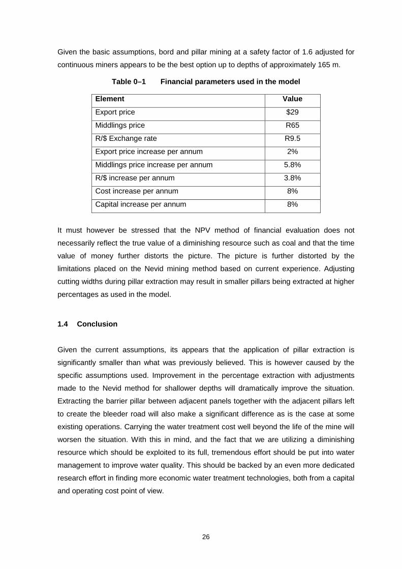
Table 1–1 Financial parameters used in the model ...................................................26
Table 3–1 Coal mines – Accident data 1984 to 1998 (after Department of Minerals
and Energy, 1999) ................................................................................................64
Table 4–1 Accidents and production related to the safety factor ................................68
Table 4–2 Condition of pillars related to age ..............................................................70
Table 4–3 Condition of pillars related to safety factors...............................................70
Table 4–4 List of mines and status of checklists ........................................................71
Table 6–1 Pillar widths required for a SF of 2.0 .........................................................99
Table 6–2 Dimensions for stooping at various depths.............................................. 101
Table 7–1 Potential safety hazards in multi-seam mining layouts (after Hill, 1994) .. 106
Table 8–1 Percentage stress reductions on the artificial barrier pillars due to
backfilling ........................................................................................................... 131
Table 10–1 Classes for probability of occurrence ...................................................... 146
Table 10–2 Relationship between probability of unsuccessful pillar recovery and risk
rating values ....................................................................................................... 148
Table 10–3 Categories for typical pillar extraction scenarios ..................................... 150
Table 11–1 Differences between four selected mining methods ................................ 157
Table 11–2 List of requirements for successful application of methods and their relative
importance ......................................................................................................... 160
Table 11–3 Checklist to determine if mining methods are eliminated by panel
constraints .......................................................................................................... 162
Table 11–4 Example of panel and mining method assessment ................................. 163
Table 11–5 Studies and data collection required to evaluate method requirements ... 163
Table 0–1 History of pillar extraction developments in Australia (after Shepherd
& Chaturvedula, 1991, with additions by the author) ..................................... 206
Table 0–2 Employees per extraction panel at Bellambi West Colliery ............... 211
Table 0–3 Employees per extraction panel at Charbon Colliery ......................... 216

17
Introduction
1.1 Importance of secondary extraction
The aim of Coaltech 2020 is to extend the life of the Witbank coalfield beyond 2020. Large
areas of this coalfield have previously been mined using the bord and pillar extraction
method, leaving significant amounts of coal in the pillars. However, the constraints on
secondary pillar extraction imposed by geotechnical, rock engineering, environmental and
economic factors may have an adverse effect on their potential for being mined.
South Africa is considered to have between 55 and 58 billion tons of coal reserves, of
which approximately 29 per cent are found in the Witbank and Highveld Coalfields
(Jeffrey, 2000).
South Africa is currently the second-largest exporter of hard coal in the world. In 1998,
60.5 million tonnes of steam coal, 5.7 million tonnes of metallurgical coal and 1.3 million
tons of anthracite were exported (Jeffrey, 2000).
Baxter (1998) investigated the total coal production of South Africa for the period 1996 to
1997. He concluded that the South African coal mining industry produced 109 million
tonnes of coal (ROM) from underground bord-and-pillar workings in 1997.
Madden et al. (1995) investigated the dimensions of underground bord-and-pillar workings
for more than 350 panels in South Africa (refer to Figure 0–1). The average dimensions
were given as:
Bord width : 6.0 m
Mining height : 2.8 m
Pillar width : 15 m
Depth : 101 m
Safety factor : 2.82.
From these figures the number of pillars left underground in 1997 can be calculated as
follows:
1. Volume of one pillar : 630 m3

18
2. Total volume of mined area (one pillar) : 1 234.8 m3
3. Extracted volume : 604.8 m3
4. Weight of extracted volume : 967.7 tonnes
5. Total pillars left u/g in 1997 : 112 641
6. Total volume of pillars left u/g : 70.9 million m3
7. Amount of coal left u/g in 1997 : 113.5 million tonnes.
15 m
6.0 m
6.0 m
15 m
Total extraction area of one pillar
21 m
21 m
15 m
6.0 m
6.0 m
15 m
Total extraction area of one pillar
21 m
21 m
Figure 0–1 Average dimensions of underground bord-and-pillar workings in
South African collieries (after Madden et al., 1995)
The above figures indicate that the average underground extraction ratio was just less
than 50 per cent.
Assuming that the average bord-and-pillar coal production ratio has been 35 per cent of
the annual ROM production since 1970, the above figures can be extended using the
production figures obtained from the Department of Minerals and Energy (Figure 0–2).
From Figure 0–2 it can be calculated that:
• For the period 1970 to 1997, 1.68 billion tonnes of coal was left underground
• More than 1.7 million coal pillars have been left underground since 1970
• This covers an area of 27 x 27 km (729 km2)
• Sufficient coal is left in the pillars to sustain ROM production for 17 years,
excluding barrier pillars.

19
Figure 0–2 Estimated underground bord-and-pillar coal production for the period
1970 to 1999
Note that these figures are based on the assumption that the bord-and-pillar production
rate has remained at 35 per cent of the total production since 1970. However, in the
earlier years this figure was probably higher. Moreover, Baxter (1998) separated
underground primary production and pillar-extraction figures in his paper. This indicates
that none of these pillars will be extracted, i.e. 109 million tonnes of coal is produced only
from primary bord-and-pillar mining. In other words the production of 109 million tonnes of
coal is excludes the production that came from pillar extraction.
In another study, Hardman (1989) estimated that 1.7 billion tonnes of coal in 4 million
pillars over an area measuring 32 x 32 km remains as a consequence of bord-and-pillar
mining in South Africa.
1.2 Increased extraction
In order to obtain the potential increase in reserve utilisation, a comparison was drawn
between the theoretical percentage extraction for a number of different mining approaches
0
20
40
60
80
100
120
1970 1975 1980 1985 1990 1995
Years
Un
der
gro
un
d b
ord
an
d p
illar
RO
M (
mill
ion
to
nn
es)

20
at varying depth. The following different mining approaches were evaluated in terms of
impact on percentage extraction of coal and life of the reserve area: -
• Normal bord and pillar mining at a safety factor of 1.6 as per Salamon formula.
• Bord and pillar mining at a safety factor of 1.6 as per Salamon formula, but adjusted
for continuous miner application.
• Bord and pillar mining at a safety factor of 1.2 as per Salamon formula with
subsequent ashfilling.
• Bord and pillar mining followed by pillar splitting.
• Bord and pillar mining followed by pillar splitting and quartering.
• “Full pillar extraction” as applied at Middelbult.
• The Nevid method of pillar extraction.
• Bord and pillar mining at a safety factor of 1.6 as per van der Merwe (2000) formula.
A number of very general and broad assumptions had to be made to simplify calculations
and relative comparison of the results.
• In all cases panels were restricted to 7-road layouts.
• Solid barrier pillars were left around all panels.
• The coal left in the barrier pillars formed part of the calculation.
• A minimum width to height ratio of 2.5 was used in pillar design.
• A minimum initial safety factor of 2.0 is required for pillar extraction.
• A minimum pillar size of 18 m is required for effective splitting in the so-called full pillar
extraction as applied at Middelbult Colliery and the Nevid method of pillar extraction.
• The final ribs after splitting in pillar splitting must have a width of at least the mining
height.
• The remaining pillars after splitting and quartering in pillar splitting and quartering must
have a width of at least 1.3 the mining height.
• In pillar splitting and quartering, a full row of pillars is left on one side of the panel to
provide for a bleeder road.
• In “full” pillar extraction, a full row of pillars is left on either side of the panel to provide
for a bleeder road.
• In the Nevid method, a full row of pillars is left on the one side of the panel and two-
thirds of a row on the other side to allow for a bleeder road.
• In “full” pillar extraction only 60 per cent of the coal in each pillar is recovered due to
spillage and inconsistent cutting. This is based on practical experience at Sasol Coal.

21
• In the Nevid method, the percentage extraction is calculated theoretically based on the
cutting layout as a result of less spillage and easier adherence to the layout.
In all cases the overall percentage extraction can be increased somewhat by mining the
barrier pillar between adjacent panels creating larger compartments. Extracting the barrier
pillar and the solid pillars left on one side of a panel during secondary mining and leaving
only a bleeder road around the outer reaches of larger compartments can significantly
increase overall extraction.
Increasing the number of roads also improves the overall percentage extraction in all
cases, but at greater pillar sizes, productivity suffers and shuttlecar cable length may
become a limiting factor. At shallower depths and smaller pillar centres this should
become a serious consideration.
It must further be borne in mind that with all high extraction methods at shallow mining
depth predictability and consistency of goafing may become a major problem. Severe
surface subsidence and damage further aggravate the problems. The methods discussed
in this document definitely require further investigation for shallower depths.
Figure 0–3 presents the results for the percentage extraction for the various mining
methods at depths ranging from 50 m to 175 m.
For both pillar extraction and the Nevid method, the percentage extraction remains
constant up to approximately 150 m. This is a result of the minimum pillar size
requirement set by the mines from a practical cutting layout. For the splitting and splitting
and quartering alternatives, a similar correlation is found at the shallower depths. This is a
result of the overriding requirement of width to height ratios for the final ribs or pillars.

22
Figure 0–3 Percentage extraction ratios for various mining methods
As can be seen from this Figure that the various bord and pillar alternatives are doing
better than the pillar extraction alternatives at shallow depths. This is primarily as a result
of the selected minimum pillar requirements for the pillar extraction methods. There are
currently mines practicing pillar extraction on smaller pillars with different cutting layouts
and sequences with good results. The continuous miner adjusted safety factor of 1.6 and
the low safety factor of 1.2 based on the Salamon formula gives similar results for mining
at very shallow depth. Both splitting and splitting-and-quartering of pillars up to
approximately 150 m depth and the pillar extraction alternatives at shallower depths up to
approximately 80 m may result in unstable mining conditions and should be approached
with great care. As the safety factor is some reflection of the ability of the remaining coal
to carry the load of the overburden, it can be deduced that the higher the percentage
extraction, the greater the possibility that the remaining coal pillars or snook will fail. The
critical issue is the safe time to failure, which becomes very unpredictable with
inconsistent snooks dimensions and small pillars at shallow depth. Splitting and splitting
and quartering of pillars to achieve the indicated percentage extraction above may be far
too risky especially in the 75 m to 125 m depth range and should rather not be
considered. One of the other methods should be employed in these situations.
From approximately 80 m, pillar extraction appears to be the best alternative from a
reserve utilization point of view, followed by mining at a safety factor of 1.2 with
0
10
20
30
40
50
60
70
80
90
50m 75m 100m 125m 150m 175mDEPTH
Per
cen
tag
e ex
trac
tio
n (
%)
B&P @ 1.6 SFB&P @ 1.2 SFB&P+SB&P+S&QNEVIDB&P+FPECM ADJUSTEDNIELEN
0
10
20
30
40
50
60
70
80
90
50m 75m 100m 125m 150m 175mDEPTH
Per
cen
tag
e ex
trac
tio
n (
%)
B&P @ 1.6 SFB&P @ 1.2 SFB&P+SB&P+S&QNEVIDB&P+FPECM ADJUSTEDVan der Merwe
0
10
20
30
40
50
60
70
80
90
50m 75m 100m 125m 150m 175mDEPTH
Per
cen
tag
e ex
trac
tio
n (
%)
B&P @ 1.6 SFB&P @ 1.2 SFB&P+SB&P+S&QNEVIDB&P+FPECM ADJUSTEDNIELEN
0
10
20
30
40
50
60
70
80
90
50m 75m 100m 125m 150m 175mDEPTH
Per
cen
tag
e ex
trac
tio
n (
%)
B&P @ 1.6 SFB&P @ 1.2 SFB&P+SB&P+S&QNEVIDB&P+FPECM ADJUSTEDVan der Merwe

23
subsequent ashfilling. During low safety factor mining, the stability of the area together
with the risk of pillar failure whilst mining and ashfilling is still in process as part of
Coaltech 2020. The continuous miner adjusted safety factor of 1.6 at shallow mining,
however approaches the unadjusted 1.2 safety factor in terms of percentage extraction
and pillar sizes, indicating similar risk. The same is true for mining at a 1.6 safety factor
according to van der Merwe (2001) at the greater depth of 150 to 175 m. If the continuous
miner adjustment and the van der Merwe strength formulae are acceptable, mining at a
1.2 Salamon and Munro (1967) safety factor would almost not require ashfilling.
In general, it can be concluded that from a reserve utilization point of view, bord and pillar
mining only should be recommended for mining at depths up to approximately 80 m,
except if alternative pillar extraction methods or layouts can be developed. From 80 m
onwards some form of pillar extraction should be implemented. Although splitting and
splitting and quartering appear attractive in the middle depth ranges, the risk associated
with these approaches may be unacceptable.
1.3 Financial value of increased extraction
1.3.1 Production scenario’s
A hypothetical reserve area of 154 Mt in-situ mineable coal of 3 m thickness was
theoretically mined to depletion at a constant rate of 4.5 Mtpa with 5 different mining
approaches. This was repeated for depths varying from 50 m to 175 m in order to assess
the impact of depth on the percentage extraction and the resultant economy of the
approach. Similar mining layouts were used in all cases to ensure maximum consistency
in the comparisons. The basis for the financial evaluation and comparison was the NPV
(net present value) of the cash flow generated over a period of 27 years. This is the
maximum mine life that could be generated in the exercise. The impact of water treatment
associated with pillar extraction was considered only up to year 27 in all cases as
discounting of numbers beyond that timeframe is very insignificant. It should be noted
though that water treatment will most probably carry on well beyond that date.
The 5 mining approaches evaluated were :-
• Bord and pillar mining at a 1.6 safety factor.
• Bord and pillar mining at a 1.6 safety factor adjusted for continuous miner application.
• Bord and pillar mining at a 1.2 safety factor, followed by ashfilling.

24
• Bord and pillar mining at a 1.2 safety factor adjusted for continuous miner application,
followed by ashfilling.
• The Nevid method of pillar extraction.
In the ashfilling approach, the area was backfilled with a cemented ash to approximately
one third of the original mining height, resulting in a residual safety factor of 1.6 based on
the assumption that the backfill will have the same strength as the coal. Although, this is
not true in reality, it was though this aspect requires a very detailed research, and it is not
the scope of this project.
Capital required to establish a new mine with a 4.5 Mtpa production capacity was
estimated at R638 million and a multi stage washing plant with stockpiles and rapid load-
out facilities including railway links at R730 million. In the base model it was assumed the
export yield would amount to 35 per cent and middlings yield to 50 per cent. Cash
operating cost for mining was estimated at R45.5 per RoM tonne for bord and pillar
development and R43 for pillar extraction. The difference is primarily related to lower coal
cutting and roof support costs.
1.3.2 Pillar extraction and ground water inflow
During pillar extraction, the goaf migrates through the overlying strata into the
groundwater aquifer in almost all cases, resulting in an inflow of groundwater into the mine
workings. Over time, the volume of water reporting underground is largely a function of the
rainfall. It is estimated that on average 8 per cent of the mean annual rainfall recharges
the groundwater system and ends up underground in the mine. This figure is however
dependant on a number of variables and could range from a low 3 per cent to a high 15
per cent. Rainfall also varies significantly from year to year. In the base model a recharge
rate of 8 per cent and an average rainfall of 750 mm per annum were used.
In the underground workings, the water is contaminated through chemical and biological
processes in the presence of various minerals. The longer this process, the worse the
resulting water quality. In the model, it is assumed that water is pumped to surface and
treated as soon as possible, which should result in lower overall treatment costs. Water
treatment plants are built in increments of 1 Ml per day capacity following the profile of
increasing groundwater inflow. The model uses a capital estimate of R20 million per 1 Ml
per day capacity as baseline. Comparison of actual figures in industry is currently as high
as approximately R40 million, and operating cost of R6000 per 1 Ml treated. Lower cost

25
alternatives are in the process of development and better water management will result in
better water quality and lower costs.
1.3.3 Low safety factor mining followed by ashfilling.
In this case the reserve is mined at a safety factor of 1.2 adjusted for continuous miners.
This results in the smallest pillar sizes and highest percentage extraction for any given
safety factor and mining situation, but also results in the weakest pillar strength and most
unstable mining condition at any given safety factor as discussed in Section 3. This poses
the highest risk during mining and subsequent ash filling and the potential time to failure of
pillars may force alternative mine layouts to reduce panel length and time of exposure.
Failure of pillars before solidification of the ash may result in failure of overburden and
flooding of adjacent workings with water and ash.
With a cemented ashfilling of final strength equivalent to the strength of coal (assumption),
the mined out area must be back filled with ash to reduce pillar height to two thirds of the
original mining height to increase the residual safety factor to 1.6. This implies filling at
least one third of the mined out volume with ash, which would require 1,000,000 cubic
meters of filling material per annum.
Capital provided for backfill infrastructure in the base case in the model amounts to R35
million, with operating cost of R10 per cubic meter placed.
1.3.4 Financial evaluation.
Table 0–1 shows the financial parameters that were used in the modeling.
Modeling the above scenario produced the following result at various mining depths: -
(insert NPV @STD COST)
From the above comparison it appears that pillar extraction only becomes viable beyond
approximately 150 m given the current assumptions when compared to bord and pillar
mining at a safety factor of 1.6 adjusted for continuous miners. Furthermore mining at a
safety factor of 1.2 is only more viable than pillar extraction at depths of approximately 75
m and shallower, and will only surpass bord and pillar mining at a safety factor of 1.6
much deeper than 175 m.
26
Given the basic assumptions, bord and pillar mining at a safety factor of 1.6 adjusted for
continuous miners appears to be the best option up to depths of approximately 165 m.
Table 0–1 Financial parameters used in the model
Element Value
Export price $29
Middlings price R65
R/$ Exchange rate R9.5
Export price increase per annum 2%
Middlings price increase per annum 5.8%
R/$ increase per annum 3.8%
Cost increase per annum 8%
Capital increase per annum 8%
It must however be stressed that the NPV method of financial evaluation does not
necessarily reflect the true value of a diminishing resource such as coal and that the time
value of money further distorts the picture. The picture is further distorted by the
limitations placed on the Nevid mining method based on current experience. Adjusting
cutting widths during pillar extraction may result in smaller pillars being extracted at higher
percentages as used in the model.
1.4 Conclusion
Given the current assumptions, its appears that the application of pillar extraction is
significantly smaller than what was previously believed. This is however caused by the
specific assumptions used. Improvement in the percentage extraction with adjustments
made to the Nevid method for shallower depths will dramatically improve the situation.
Extracting the barrier pillar between adjacent panels together with the adjacent pillars left
to create the bleeder road will also make a significant difference as is the case at some
existing operations. Carrying the water treatment cost well beyond the life of the mine will
worsen the situation. With this in mind, and the fact that we are utilizing a diminishing
resource which should be exploited to its full, tremendous effort should be put into water
management to improve water quality. This should be backed by an even more dedicated
research effort in finding more economic water treatment technologies, both from a capital
and operating cost point of view.

27
Considering ashfilling, it should be realized that given the requirement of strength and
stabilizing properties, it is highly unlikely that suitable ash mixtures can be developed
within the cost framework. In addition, the determination of suitable strength of ashfill
requires a detailed research project.
28
Research methodology
The research commenced with a literature survey to review previous work done on the
subject of increased extraction of coal reserves. This covered both the local and
international coal mining experience. The objective of the literature survey was to
establish the current level of knowledge and to identify the constraints of current mining
methods in terms of pillar extraction, as well as to identify possible methods for future
application in the research. This led to the compilation of a questionnaire to be used as a
base for structured visits to selected pillar extraction operations.
The literature survey was followed with visits to various pillar extraction operations in
South Africa and in Australia to gain first hand knowledge of the South African and
Australian pillar extraction experience. The objective was again to further identify factors
constraining and limiting pillar extraction applications and possible methods to include in
the research. These were aimed at issues such as the environment, strata control, roof
and floor stability, ventilation, mining methods and health and safety implications. The
interrelationship of these factors was required for the development of various risk
assessment and evaluation models.
The site visits and literature survey were followed by industry workshops in which
feedback was given to a number of selected industry role players with the objective to
develop further interaction with the industry and to brainstorm and discuss existing and
possible new mining methods for future application.
A number of models were then developed for use in the evaluation and selection of
possible methods for future pillar extraction operations. The theoretical percentage
extraction of various approaches to high extraction mining methods was compared over
varying mining depths below surface. The potential economic benefit of increased
extraction against the additional cost of environmental protection/remediation was
modelled. The various factors identified that constrain and limit the application of pillar
extraction were subsequently built into models for doing risk assessments relating to
mining and rock engineering. The research was concluded with a model that assists in the
selection of the most appropriate mining approach for any given panel

29
Literature survey
1.5 Introduction
It has been established that an increase in the utilisation of South Africa’s coal resources
is needed, both to sustain this industry and to ensure that offshore revenue from exports
is maintained. Previous extraction of the coal reserves has been done predominantly by
the bord-and-pillar method of mining, with percentage extraction by this method (by
means of primary and secondary extraction of pillars) accounting for approximately 50 per
cent. This implies that almost half of the extractable coal reserves in the Witbank and
Highveld coalfields remain to be unexploited. Considering that coal mining has taken
place in this region for more than a century, a sizeable volume of coal is obviously still
available for economic exploitation.
This literature review identifies and discusses the factors associated with the removal of
previously developed coal seams, i.e. pillar extraction. These factors include the mining
methods, the coal pillars, and the safety aspects related to this mining practice.
1.6 Mining methods
Longwall mining has been practised successfully in South Africa since the late 1970s.
However, due to the presence of geological anomalies and the varying thickness of the
coal seams, it can only be practised in selected portions of the total reserves (Beukes,
1989). The other, more dominant, mining method employed since the inception of coal
mining in South Africa is bord and pillar. The percentage of coal lost as a result of larger
pillars being left in bord-and-pillar workings the deeper one goes was a major factor
identified by Wagner (1981) as indicating the need to increase the total percentage
extraction of coal reserves. It therefore became necessary to investigate other mining
methods for improving the overall extraction percentage of the total coal reserves.
Pillar extraction (or stooping) has been practised for many years in South African collieries
as a means of increasing the percentage extraction from the in situ coal reserves.
Optimised recovery is the main objective in pillar extraction. Early efforts with this mining
method in the Witbank area were not as successful as in the deeper, thin seams of Natal
(Salamon and Oravecz, 1973). Handgot methods (hand lashing with spades) of pillar
extraction have been replaced mainly by mechanised methods, using either conventional
mechanised equipment or, more commonly, continuous miners. As a means of increasing

30
the percentage extraction, pillar extraction has certain advantages over the highly
mechanised longwall method, which will be discussed later. Mark and Chase (1999)
describe a computer program (called Analysis of Retreat Mining Pillar Stability, or
ARMPS) that is used as an aid in the design of pillar extraction operations. This and other
design tools are further discussed in the section on Design of Suitable Areas (Sub-section
1.9.3.8).
1.6.1 Decision-making considerations for pillar extraction
Plaistowe et al. (1989) suggest that consideration should be given to optimising extraction
on the basis of coal qualities and not on a purely volumetric extraction basis. They further
develop a logic sheet to ensure that every possibility or opportunity has been identified.
From this, areas are identified from which higher extraction would be obtained by pillar
extraction and those from which higher extraction would be obtained by bord-and-pillar
mining. This analysis does not take into account losses from geological disturbances.
Livingstone-Blevins and Watson (1982) state that it must be ensured that pillar extraction
is the most appropriate method to the prevailing circumstances.
Plaistowe et al. (1989) suggest further criteria for decision-making about pillar extraction,
highlighting the mining method, speed of extraction, ventilation and choice of equipment
as important factors. Livingstone-Blevins and Watson (1982) suggest similar decision-
making criteria.
Wagner (1981) suggests that compared with longwall mining, pillar extraction methods
offer the advantages of lower capital cost and greater flexibility with regard to geological
disturbances. He further comments that pillar extraction methods not only have the
potential to supplement longwall mining but also in many instances could replace this total
extraction method. Furthermore, he mentions that compared with longwall mining, the
pillar extraction method makes maximum use of the load-bearing capabilities of coal,
thereby avoiding the need for powerful artificial supports, which are the main feature of the
longwall mining system. Blaiklock (1992) adds that pillar extraction is often employed in
deeper, high-value seams where recovery rates would be unacceptably low if only
development bord-and-pillar mining was conducted.
1.6.2 Planning for pillar extraction

31
It is clear from the introduction that bord-and-pillar mining has been, is and, for the
foreseeable future, will remain the primary underground mining method for coal extraction
in South Africa. Livingstone-Blevins and Watson (1982) and Willis and Hardman (1997)
maintain that pillar-extraction mining can come from only two sources: old pillar workings
or virgin coal. It follows that in old workings, planning can only optimise the given
circumstances (in terms of the original safety factor, the prevailing geological and other
conditions, etc.), whereas in virgin coal, planning can play a more effective role. Most coal
seams in South Africa have been mined by the bord-and-pillar method and the historical
panel designs did not cater for secondary extraction of pillars by pillar-extraction mining.
Livingstone-Blevins and Watson (1982) make further mention of the importance of the
panel system (with its associated barrier pillars) in coal mine design. The major advantage
of this system is that the extent of fire or pillar collapse can be confined. Other advantages
are that pillar extraction can commence before primary mining has been completed and
that panels can be designed specifically for ventilation. Panel design came into favour
only after recommendations made by Salamon and Munro in 1967, in which they indicated
that a large proportion of bord-and-pillar workings were not designed in panels (Salamon
and Munro, 1967). Livingstone-Blevins and Watson (1982) further suggested that panel
design is limited by the area available, and could be limited by geological conditions or
surface boundaries.
Pillar extraction can be conducted in two ways, namely advance or retreat. Retreat pillar
extraction is conducted on completion of primary mining, whereas advance pillar
extraction is conducted simultaneously with primary mining. This report concerns itself
with the pillar extraction of existing bord-and-pillar workings, with the emphasis being on
the retreat method of pillar extraction.
Stooping practice in South Africa can be divided into two basic methods: pillar extraction
and rib pillar extraction. Beukes (1989) highlights the difference between the methods:
“Pillar extraction – the panels consist of a bord-and-pillar mining layout where
many pillars are created but only extracted at some later date as a panel must be
developed completely before pillar extraction can commence. There are two basic
approaches to pillar extraction. Firstly, the extraction of pillars in old workings
where little or no account was taken of secondary extraction during the initial panel
and pillar design, and secondly, the extraction of pillars in panels designed
specifically for pillar extraction.

32
“Rib pillar extraction – the panels are created by means of primary development
consisting of three to four roads. Secondary development is then used to cut the
panel into 42 to 72-m wide ribs. Rib pillars, normally referred to as fenders, are
then developed and extracted very soon after creation. The only exception is the
pillars created by the primary and secondary development which are extracted as
the section retreats.”
Wagner (1981) makes the following comments on the basic principles of pillar extraction:
“All pillar-extraction methods have in common that the extraction panels in the
primary mining phase pillars are developed which are then extracted in the second
phase of the operation. The main objective of the pillars is that they should provide
support of roof strata during the primary and secondary mining stages thereby
protecting men and equipment against roof falls and regional collapses. However,
as the supporting pillars are reduced in size during the actual pillar-extraction
phase, they lose the ability to support the weight of the overburden. Pillar-
extraction layout must therefore be designed in such a manner that the support of
the superincumbent strata during the extraction of an individual pillar or number of
pillars is taken over by neighbouring pillars. The support role of the coal during the
extraction of a pillar is reduced to that of providing support to the immediate roof
strata. In the final stages of extraction of a pillar, this support is removed as well
and the temporary support of the exposed roof which relies entirely on roof bolts
and sticks that were installed during the primary and secondary phases of mining.
Once the pillar has been extracted and men and equipment have been withdrawn,
the temporary support that is mostly in the form of sticks is removed to encourage
the roof strata to cave. This latter part of pillar extraction is an integral part of the
pillar-extraction method and failure of the strata to cave in the mined-out area can
jeopardise the success of this mining method.”
1.6.3 History of pillar extraction
The method of pillar extraction offers the possibility of a high degree of recovery of
reserves. This method of mining practised widely with success in the thin and relatively
deep-lying coal seams of KwaZulu-Natal. Early efforts at pillar extraction in the thicker and
often shallower coal seams in the Witbank area did not meet with similar success. These

33
operations often resulted in mine fires by spontaneous combustion as a result of the large
amount of broken coal left behind.
Pillar extraction is not practised widely in European collieries, partly because the coal
seams are located at comparatively great depths (300 m or more below surface), which
has encouraged the use of longwall techniques that are inherently safer. Australia, the
USA and South Africa delayed the use of longwall mining due to its high capital cost and
because their coal seams are at shallower depths (generally less than 300 m). A further
point is that longwall mining demands comparatively undisturbed coal seams to be cost-
effective.
The first experiments with rib-pillar mining in South Africa were modelled on the methods
that were successfully used in New South Wales, Australia. These methods, namely
Munmorrah, Wongawilli and Old Ben, are all rib pillar-extraction methods using continuous
miners. Each of these methods (as originally employed) is briefly discussed below
(Beukes, 1989).
1.7 International experience
1.7.1 The Wongawilli system
A panel is created by a secondary development consisting of three to five roads, leaving a
continuous pillar of coal between the development and the previously caved area. This
pillar of coal is normally between 50 and 150 m wide and is extracted by developing and
extracting 7-m-wide ribs in a modified split-and-lift system. The pillars formed by the
development are extracted as the rib extraction retreats. As a result of the length of the rib
pillars, this method resembles a shortwall face. A typical Wongawilli layout is shown in
Figure 0–1.

34
Figure 0–1 Typical plan view of the Wongawilli system (after Skybey, 1982)
The main disadvantages of the system are:
• Excessive floor lift when splitting successive headings in a large panel
• Difficulties when removing snooks on the return run out of each heading
• Difficulties with ventilating rib-pillar panels when the roof caves completely, filling all
voids in the goaf area.
1.7.2 The Munmorrah system
The Munmorrah system is practised at an average depth of 180 m below the surface. The
coal seam is on average between 1.8 and 3.0 m thick and is hard, making it difficult to cut
with a continuous miner. The floor is composed of soft shales and floor heave often
occurs due to pillars being forced into the soft floor. The rib pillars are normally 1 200 m
long and 183 m wide, and are developed on either side of the main development. The

35
primary development consists of three roads, with the bord width being 5.5 m and the
pillar sizes 26 m x 40 m centres. Figure 0–2 shows a typical extraction sequence and
layout of this mining system.
Figure 0–2 The Munmorrah mining system (after Beukes, 1989)
1.7.3 The Old Ben method
This method is very similar to the Munmorrah method and was developed after a very
serious accident occurred in which the very thick, competent conglomerate overlying the
coal seams caused sudden, unplanned roof falls. Here, the secondary development
consists of three roads, leaving reserves for pillar extraction on either side. The total panel
width is more than 200 m. Tertiary development, consisting of three roads, is done
towards the end of the panel. From this development, short fenders are then developed
and extracted. A typical layout of this method is shown in Figure 0–3.

36
Figure 0–3 The Old Ben mining method (after Beukes, 1989)
Chase et al. (1997) describe various pillar-extraction methods employed in US coal mines,
viz. the Christmas tree and outside lift, which will each be discussed in turn.
1.7.4 The Christmas tree method
This method is employed under deep cover when pillars on 18 or 24-m centres are
required to maintain the necessary stability factors. Figure 0–4 depicts a common
sequence in which lifts are extracted during barrier and production-pillar extraction. This
layout shows the use of mobile powered supports. Since the area most prone to roof fall in
pillar extraction is the intersection, use of mobile powered supports can enhance the
stability of these areas, and allows non-essential personnel to retreat further from the goaf
edge.

37
Figure 0–4 The Christmas tree extraction method. A, lifts 1-2A. B, lifts 1-8A. C,
lifts push; pushout removal units 1 and 2 in tandem. D, lifts 1-push; pushout
removal with units 1 and 2 staggered (after Chase et al., 1997)
1.7.5 The outside lift method
This method is generally used under less than 120 m of cover. Entry spacings are
typically about 15 m, with cross-cuts on 25 to 37-m centres. Since these pillars have both
a long and a short axis, they contain less coal and a large amount of time is spent
tramming machinery. Chase et al. (1997) argue that this method is safer than the
Christmas tree method. This is so, they claim, in areas under weak roof conditions
because the unsupported span of the mined-out area is smaller than with the Christmas
tree method. The main disadvantage of this method compared with the Christmas tree
method is that the lift lengths are usually deeper, and prolonged exposure while mining
them subjects the continuous miner to greater risk. Figure 0–5 shows a typical outside lift
sequence.

38
Figure 0–5 Outside lift method. A, lifts 1-6; B, lifts 1-7A; C, lifts 1-push (after
Chase et al., 1997)
The Christmas tree and outside lift methods have been used successfully in combination
to extract parallelogram-shaped pillars developed by continuous haulage, called the
herringbone panel design. Chase et al. (1997) further describe variations of these total
pillar-extraction techniques, and also discuss partial pillar-extraction techniques.
1.7.6 Summary of findings of pillar extraction in New South Wales
The full and partial extraction methods as examined in New South Wales were all
implemented and designed around specific economic and geotechnical requirements of
the individual operations. The choice of a partial versus a full extraction system appeared
to be based on the following factors:
• Surface subsidence
• Nature of the immediate 15 m roof
• Geological nature of the potential goaf zone
39
Of the three partial extraction operations detailed, Munmorah and Cooranbong were
overlain by a massive conglomerate which created previous problems with full extraction
systems such as windblasts which previously had damaged both life and equipment.
Additionally, these two operations were undermining sensitive areas, which precluded
them creating a goaf. Although no surface subsidence was expected, the limited
subsidence measured was probably a result of these collieries operating in a soft floor
environment which resulted in the panel consolidating into and punching the soft floor.
The operation at Clarence Colliery precluded full pillar extraction as a result of two
aquifers overlying the coal seam, as well as the massive Triassic sandstone roof, which
caused caving hazards similar to those of Munmorah and Cooranbong Collieries.
Previous full extraction had broken these aquifers and resulted in the operation still having
to pump 14 – 18 megalitres of water per day from the workings as a result of the
continuous water inflow into the workings. This, together with the complex vertical joint
sets in the lease area required a partial mining method to avoid the hazards associated
with these geological occurrences.
These three partial pillar extraction-mining operations used modifications of pillar
stripping, designed specifically at Cooranbong Colliery to maximise extraction without
creating surface interferences. The introduction of this method has ensured an increase of
the overall extraction at the collieries of between 25 – 50 percent. All three operations
used a remote control Joy 12CM type continuous miner and 2 – 3 15 tonne shuttle cars. In
all cases the continuous miner cutter head was 3.6 m wide during extraction (as opposed
to 5.5 m wide during panel development) and, where applicable, the on board roofbolt drill
rigs removed prior to extraction commencing. ABLS’s were used at Munmorah and
Cooranbong Collieries, but were not used at Clarence Colliery. The inference drawn from
this is that at the mining depth, the massive sandstone roof and the comparatively low
overall extraction at Clarence Colliery resulted in a sufficiently safe working environment
to preclude their use.
Of the full pillar extraction operations, two utilised modified Wongawilli methods designed
to suit their individual conditions. At Bellambi West Colliery this was the most suitable
extraction method given the pre-developed nature of the panel, while at Charbon Colliery
the panels were specifically designed to accommodate this type of extraction. Of the other
two full pillar extraction operations, Ivanhoe Colliery utilised an open ended system and
United Colliery utilised an extraction method resembling the pillar stripping method, with
40
the main difference being that the resultant fenders collapse rather than provide a support
to the roof cantilever. This implies that this pillar stripping can be used for both full and
partial extraction, with the failure mechanism of the method being the competence of the
immediate overlying strata. All of the full extraction operations visited had no restriction on
the amount of surface subsidence that they created. All four operations operated under
either predominantly sandstone or mudstone roof which readily caved and closely
followed the line of extraction. There was no sterilisation of economic reserves as result of
the full pillar extraction operations. The rib spall at Ivanhoe Colliery was assumed to be
primarily a factor of the age of the pillars, although additional factors could have
contributed to this. The rib spall at United Colliery was attributed primarily to the geometry
of the panels in relation to the seam dip, which resulted in unusual, and high abutment
stresses. Little rib spall was associated with the modified Wongawilli methods as these, as
described before, extract the pillars as they are created, limiting the effects that time might
have on them. All the full pillar extraction operations employed remote controlled Joy
CM12 continuous miners (all with a 3.6 m wide cutter head) with either 2 or 3 15 tonne
capacity shuttle cars and 2 or 3 remote controlled ABLS’s. In instances where there were
on-board roofbolting rigs, these were removed prior to extraction commencing.
Both the full and partial pillar extraction operations conducted lifting of pillars on retreat
and at an angle of 60°.
On the whole, issues pertaining to safety and cost of the operations could not be obtained
as the information was of a confidential nature. In the 1999/2000 financial year however, 3
fatalities occurred on mining operations in New South Wales with a lost time injury
frequency rate of 43 and a lost time injury incidence rate of 9 for underground operations
(Anon, 2001). These figures are consistent with those reported for the 1998/1999 financial
year. As for the cost aspect, the operations attributed the absence (or lower usage) of roof
support, lower consumption of continuous miner picks and lower labour (usually 2 – 3 less
than a development bord and pillar section) during extraction as factors contributing to
operating costs being generally lower during pillar extraction.
The overall review of the pillar extraction operations in New South Wales as presented
here highlights some of the more casual and general issues surrounding the choice of
extraction method.

41
1.8 South African experience
At the shallow depth of coal mining in South Africa, there is considerable potential for
improving the percentage extraction by utilising pillar extraction (Wagner and Galvin,
1982). Beukes (1989) states that pillar extraction in South Africa by handgot methods has
been practised for many years. Pillar extraction with mechanised equipment commenced
during the late 1960s, and approximately a decade later continuous miners were
introduced into pillar and rib-pillar extraction. Livingstone-Blevins and Watson (1982) state
that pillar extraction in South Africa can be practised using two methods, namely “open
end” and “pocket and fender”.
1.8.1 The open-end system
Livingstone-Blevins and Watson (1982) have the following to say about this mining
method:
“In this method mining takes place directly next to the goaf, creating a completely
open side. Lifts or slices are mined straight through to the goaf and the whole pillar
is extracted by a series of slices until only a ‘snook’ remains. The ’snook’ is
extracted by a last cut or two, or is destroyed, or left to crush under the weight of
the caving. The immediate roof over the slice is supported by its own cantilever
strength, supplemented by systematic support in the roadways. Additional support
and protection are installed next to the goaf line.
“Generally, the support is withdrawn and the roof allowed to cave after completion
of one lift before commencing the following one. In continuous miner installations
where whole pillars are extracted in a single lift, it may be necessary to support
large areas of roof before goafing. In large pillars, lifts are allowed to goaf, and
mining sometimes takes place from alternating sides of the pillar to give continuity
of production, and a protective coal barrier is left between the working area and
the caving ground.”
1.8.2 The pocket-and-fender system
Livingstone-Blevins and Watson (1982) state the following about the pocket-and-fender
mining method:

42
“The basis of this method is to leave a portion of the pillar unmined, possibly to be
taken later, but under no circumstances to be left in the goaf. A drive is mined into
a pillar, leaving a ‘fender’ of coal between the drive or ‘lift’. This fender is thin and
usually is left to crush or is destroyed. Alternatively, it can be much thicker and is
mined or partially mined at a later stage by driving ‘pockets’. Fenders left at the
end of the pillar should be of such dimensions as to allow limited convergence
through controlled yield without collapse, so as to act as a breaker line extension.
Fenders and snooks should crush readily after the withdrawal of artificial support;
otherwise they should not run parallel to a geological weakness, i.e. cleats,
fissures and faults. The roof is allowed to cave after completion of the lift and
fender robbing before commencing the next lift.”
The choice of method is mainly dependent on the prevailing roof conditions. Ideally, an
open-end system will be chosen whereby cuts are mined from one or two sides of the
pillar adjacent to the goaf. In less favourable conditions, the pocket-and-fender system
tends to be preferred whereby cuts are mined in the same way as in the open-end
system, except that a fender or rib of coal (or a number of small coal snooks) is left
adjacent to the goaf to serve as a temporary local support and protection.
1.8.3 Usutu method
In the Usutu method of pillar extraction, panels consisted of 9 roads at 19m pillar centers.
Bord widths were 6m, leaving pillars of 13m square. At depths ranging between 110m and
140m below surface, it resulted in factors of safety of between 2.4 and 2.8.
The systematic roof support in panel development consists of 3 resin roofbolts per row,
spaced at a 2m square grid. Roofbolts were either 1.2m or 1.5m long.
Pillar extraction was always done at a 45 degree stooping line. Extraction of pillars always
started at the top end of the line as depicted in Figure 0–6.
The detailed extraction sequence of each pillar as well as the support sequence is
depicted in Figure 0–7.
Timber breaker lines BL1 and BL2 and finger lines FL1 and FL2 are already in position as
they are installed before the previous pillar was extracted. The first cut is then made and
whilst finger line FL3 is being installed, the second cut is made on the opposite side of the

43
pillar. Cut 3 is then made whilst finger line FL4 is installed. Cut 4 is made whilst finger line
FL5 and breaker line BL3 are installed and finger line FL3 is extended. The continuous
miner then has to wait whilst finger line FL6 is installed and finger line FL4 is extended
before making cut 5. When this cut has been completed, the continuous miner moves to
the next pillar to be extracted and breaker line BL4 is installed. All breaker lines and finger
lines, except BL3 and BL4, are then extracted. (Beukes, 1989).
Figure 0–6 Usutu pillar extraction sequence (After Beukes, 1989)

44
Figure 0–7 Usutu pillar extraction method and support (After Beukes, 1989)
1.8.4 Rib pillar extraction in South Africa
During the 1960s, only 11 per cent of total reserves at Sigma Colliery were extracted.
Stooping experiments using conventional methods were employed, but these were
unsuccessful as the friable roof conditions at the colliery made conventional stooping
hazardous. A longwall system was then introduced in 1967 using chock supports, but this
also proved to be unsuccessful. A complete longwall was installed and achieved world-
class performance, but the method was only useable in localised areas. An investigation
into the pillar-extraction methods used in Australia resulted in rib-pillar extraction (modified
Munmorrah method) being introduced in 1980 in the No 2B coal Seam. By 1982 a double
continuous miner section on the No 3 Seam had been established, based on the 1980
trials which proved a great success.
The primary development at Sigma consisted of four roadways from the main
development to the limit of the remnant. The two outer roads were used as return airways,
and the two inner roads as travelling and conveyor belt roads. The inner roads also
served as intake roads. The secondary development consisted of three roads, two being

45
intake airways and one a return airway. Cross-conveyor installations were used to
minimise the tramming distance for shuttle cars. Several combinations of rib-pillar mining
were employed at Sigma Colliery. De Beer et al. (1991) and Beukes (1989) give details of
these. A typical rib-pillar extraction layout used is shown in Figure 0–8.
Rogers (1989) gives details of similar novel, but not unique, practices for rib-pillar
extraction mining at New Denmark Colliery. Gericke (1989) discusses rib-pillar mining as
conducted at Middelbult Colliery.
Beukes (1989) provides the following list of factors that determine the success of rib-pillar
extraction:
• Pre-development of fenders must be carried out accurately to ensure uniform fender
width.
• The length of fenders should be design for the behaviour of the overburden strata and
the mining height to avoid premature failure.
• Fenders must be extracted as completely as possible to avoid stress on adjacent
fenders.
• Breaker lines must be installed correctly.
• The final positions of fenders are high risks.
• Geological discontinuities must be pre-supported.
• A steady rate of advance must be maintained to avoid stress build-up.
• Timber props are less effective as breaker-line support when the mining height
exceeds 3.5 m.

46
Figure 0–8 Rib-pillar mining method layout (after Beukes, 1989)
1.8.5 Advantages of the rib-pillar system
Beukes (1989) also gives some advantages of the rib-pillar system:
• A high percentage extraction is achieved.
• Rib-pillar extraction is an effective mining method for extracting small reserves of
irregular shape that are difficult to mine using other methods, making it a flexible
mining method.
• Mining activities are concentrated in a single working area, thus resulting in improved
supervision.
• Coal is extracted from a stress-relieved area.
• Fewer intersections are created than with conventional pillar extraction, thus reducing
the risk of roof falls.
• Continuous miner operators are always under supported roof.
• The capital cost is low in comparison with longwalling, and the working and
maintenance costs are lower than those for bord-and-pillar mining.
• The ventilation that flows over the goaf serves to remove the dust and gas from the
section during fender extraction.
Wagner (1981) adds the following advantages of the rib-pillar method of mining:
• The narrow rib pillars are formed immediately before they are removed and,
consequently, these pillars are exposed to high stresses only for a short length of time.

47
Since the strength properties of highly stressed coal pillars deteriorate with time, it
follows that these pillars are stronger than pillars of similar dimensions that have been
standing for a longer period of time.
• The coal seam in the neighbourhood of these pillars has not been weakened by the
development of a regular grid of bords as in the case of conventional bord-and-pillar
mining with subsequent extraction.
• Mining equipment and personnel can operate from a well-supported bord.
1.8.6 Disadvantages of the rib-pillar system
• Once the extraction of a fender has commenced, it must be extracted completely
before there is a long break in extraction time (e.g. a weekend) to prevent pillar failure.
• Ventilation problems can be experienced when the goaf closes up completely, thereby
preventing bleeding over the goaf.
• Methane may build up in the goaf areas.
• Spontaneous combustion may occur in the goaf areas.
• There is a risk of roof falls on the continuous miner when extracting the final portion of
a fender.
1.9 Factors constraining pillar extraction
1.9.1 Ventilation
Pillar extraction is vulnerable from the point of view of ventilation in that the air quantities
should generally be greater than those employed in conventional bord-and-pillar mining
and must be sufficient to dilute the expected outflow of noxious and/or flammable gas
from the goaf (Plaistowe et al., 1989). Livingstone-Blevins and Watson (1982) add that
dust from continuous miner sections also needs to be taken into account.
Plaistowe et al. (1989) also list the following considerations with regard to goaf ventilation:
• Greater volumes of air are required to maintain air velocities in the last through road
due to leakage through the goaf area.
• Continuous monitoring of methane, carbon monoxide and air velocities is necessary.
• Changes in barometric pressure have an effect on the air-gas mixture in the goaf area
as the changes cause fresh air to enter, or a dangerous mixture of air to flow out of the

48
goaf areas. Fresh air entering a goaf area will supply oxygen, which in turn enhances
the possibility of spontaneous combustion taking place within the goaf.
• During the caving of the overlying strata, there may be a 'dome effect' along the centre
of the panel being extracted. Methane could collect in such a cavity and will not be
cleared by the normal ventilation current. Rock falls in the goaf may be accompanied
by frictional heating, which can result in methane ignitions.
• Mining at shallow depths in particular leads to disturbance of the surface strata, with
major cracking. Fresh air entering the goaf via these cracks supplies oxygen, which, in
turn, enhances the likelihood of spontaneous combustion taking place.
Beukes (1989) adds that if considerable quantities of gas are present in the seam or
overlying strata, it is advisable for individual panels to be sealed off once extraction has
been completed to prevent gases from entering the adjacent panels.
Livingstone-Blevins and Watson (1982) mention three general methods used for
ventilating pillar-extraction sections:
1. Coursing ventilation in the section
2. Coursing the return air along the goaf line
3. Bleeding the return air, or a portion thereof, through the goaf itself to an established
return airway behind the goaf.
The second method has found favour in continuous miner sections, exploiting the
permeable nature of the loosely caved goaf to clear dust, gas and used air away from the
section and not through the section.
1.9.2 Spontaneous combustion
When coal is left in the goaf, the risk of spontaneous combustion increases (Livingstone-
Blevins and Watson, 1982). Early efforts at pillar extraction were followed by mine fires
initiated by the spontaneous combustion of broken coal left behind, or of carbonaceous
shales exposed in the roof strata, and were assisted by air admitted through induced
fractures extending to the surface. Further, where other seams overlie the seam being
mined by total extraction, the upper coal will be fragmented, leading to exposure to air
with the subsequent danger of spontaneous combustion. Under these circumstances,
either pillar extraction cannot be implemented, or steps must be taken to contain
combustion.

49
1.9.3 Rock engineering aspects
1.9.3.1 Roof support
Breakerline support has successfully used in pillar extraction in South Africa. The purpose
of breaker line supports in pillar extraction is to prevent the roof collapsing from the goaf
side into roadways. There are three types of breaker lines: timber props, roofbolts and
mobile breakerline support systems.
Although timber props were used in the past, currently almost all pillar extraction is done
using roof bolt breakerlines. Livingstone-Blevins and Watson (1982) suggested that
certain conditions must be fulfilled, irrespective of the type of support used in pillar
extraction:
1. The method must provide adequate support to the workings during primary mining and
allow for abutment stresses during subsequent pillar extraction.
2. An effective breaker line must be provided to limit the extent of caving, and must be
constructed at the goaf edge, before every intended goaf and during subsequent
exposure of the goaf during the next lift.
3. As production tempos increase, the speed of installation of the support must be
increased to keep up with the extraction rate.
4. The installed support should not interfere with the movement of machinery during the
pillaring operations.
5. Local support in the workings can only be expected to hold up the immediate roof.
Timber supports were most frequently used in pillar extraction in 1970s and 1980s,
because of the simplicity of installation, and their relatively high load offering at small
compressions (Livingstone-Blevins and Watson, 1982). The converse to this is that timber
cannot provide a consistently high load during continuing compression. Their suitability for
use in high seams is also questioned, since at height the timber buckles and snaps rather
than compresses. Therefore, currently almost all the mines practicing pillar extraction use
roofbolt breakerlines and fingerlines during the extraction.

50
The main advantages of roof bolt breakerlines are (van der Merwe and Madden, 2002):
• Low cost compared to alternatives
• Can be installed during the development phase, meaning that people are not
exposed to the goaf during installation, as with standing props
• No disruption to the mining activities
• Independent of mining height, while timber props have to be thicker the longer they
are.
Powered (mobile) supports are shield-type support units mounted on crawler tracks. They
can be used during pillar extraction and eliminate the setting of the roadway, turn and
cross-cut breaker posts that are required during pillar-recovery operations. They are a
more effective ground support than timbers, and their use enhances the safety of section
personnel and reduces materials-handling injuries (Chase et al., 1997). The authors add
that the use of powered supports reduces human errors and provides consistency in the
effectiveness of installation. Livingstone-Blevins and Watson (1982) state that the size
and weight of such units in confined spaces creates additional problems. However, their
size does improve their stability. Chase et al. (1997) report that powered mobile supports
are being increasingly used in US coal mines. Powered supports have also been used
extensively in Australia (Livingstone-Blevins and Watson, 1982).
In addition to the above, Chase et al. (1997) list the following additional advantages of
mobile supports:
• They enable personnel to remain further outbye the pillar line and reduce their
exposure to the goaf overruns and rib (pillar) spalling.
• They are active supports and provide better roof coverage.
• They are better suited to handling eccentric loads (i.e. horizontal and lateral loading),
which are common during pillar extraction.
• Their size gives them stability, so shuttle cars or personnel cannot knock them out
accidentally.
1.9.3.2 Pillar design
Coal pillar design is of primary importance for the safe, economical extraction of a
valuable natural resource. Initially, pillar dimensions and road widths were based on

51
experience obtained through trial and error. Some of the errors committed have had
disastrous consequences in terms of loss of life, equipment and coal reserves (Bryan et
al., 1964; Madden, 1987).
On 21 January 1960 at 19:30, 437 people died in what has become known as South
Africa’s largest-ever mining disaster, the Coalbrook disaster. On that day 750 acres of
ground subsided onto the No 2 Seam, which resulted in the collapse of 7 000 pillars, 4
400 within a five-minute period. Bryan et al. (1964) documented the accident well. At
Coalbrook there was never any intention to extract the pillars by a second working. The
long barrier pillars, with a width no greater than that of the ordinary pillars, were not
designed with special roof-control measures, but were designed to help in the supply of
adequate ventilation to the working panels, as well as to facilitate the sealing-off of these
panels in the event of spontaneous combustion. Before 1950 there had been little mining
in excess of 3 m in height at Coalbrook, but following the erection in 1955 of a large
electricity-generating station close to the colliery, a considerable increase in demand was
experienced and a mining height of 4.2 to 4.6 m became general practice. Panels that had
been sealed were reopened and top-coaled to meet the increase in demand. This was
done with little or no roof support until a decision was taken in 1958 to support the top-
coaled areas. Mark et al. (1999a) further document other pillar collapses from around the
world.
The inquiry following the Coalbrook disaster revealed that no proven method for the
design of bord-and-pillar workings existed at that time anywhere in the world (Salamon
and Wagner, 1985). A programme of research was initiated in 1963 focusing on the
design of bord-and-pillar workings in South Africa, and the results were published in 1967
(Salamon and Munro, 1967; Salamon, 1967). Salamon and Munro (1967) derived a
formula that defined approximately the strength of coal pillars in South African collieries.
This formula was empirical in nature, being based on data obtained from a survey of
actual mining dimensions, and included information on stable and collapsed areas of
mining. The analysis of pillar design was based on the concept of a safety factor, S,
defined by the equation:
LoadPillar
StrengthPillarS =
where strength is taken to mean the strength of the pillar and load the average pressure
acting on the pillar. When actual values are substituted into the above and it is found that

52
S>1 or S<1. then these values of S can be taken to indicate that the pillar will be stable or
will fail respectively (Salamon and Munro, 1967). Further, if the strengths and loads are
predicted in some manner for a large number of cases in which pillar failure is
subsequently observed, it will be found that the safety factors calculated from the
predicted values are scattered - provided the predictions are unbiased - around unity
(Salamon and Wagner, 1985). The safety factor at which failure occurs is assumed to be
denoted by Sc. The exact value of Sc will not be known in advance, but the aim of pillar
design is to secure, with an acceptably high degree of probability, that S> Sc.
Steart (1954) derived an expression based on laboratory testing for the strength of coal
pillars. Other authors cited by Salamon and Munro (1967) have developed similar
expressions and empirical formulae for other rock types. The strength of a pillar depends
on the strength of the material of which it is composed, its volume and its shape (Salamon
and Munro, 1967). The pillar strength formula that occurs most commonly in the literature
is a simple power function composed of the volume of the pillar (in terms of its width, w,
and its height, h) and the effect imposed on the pillar by the roof, by floor friction and by
cohesion. Salamon and Munro (1967) suggest the following variation of this formula as:
βα wKhStrength =
where K, α and β are appropriately chosen constants, the values of which are defined as
7 200, -0.66 and 0.46 respectively by Salamon and Munro (1967). They further define K
as the strength of a unit cube of coal, the limitation being that this value would represent
all coal seams mined in various collieries. Madden (1989b), in his reassessment of the
work conducted by Salamon and Munro (1967), found that there was no statistically
significant difference between the strengths of individual seams so that the average
strength could represent all seams. He states that this may be the result of the anisotropic
nature of coal and the influence of local variation in material properties, as well as relating
to structural effects.
The load as mentioned above is calculated using the 'tributary area'. The limitation of
Tributary Area Theory is requires a reasonably uniform geometry and applicable where
the panel width is greater than the depth below surface; each individual pillar is then
assumed to carry the weight of the overburden above it. Load is thus calculated by:

53
)(25
2
2
kPaw
HCLoad =
where H is the depth of the floor seam (m)
w is the pillar width (m)
C is the pillar centre distance, the sum of the pillar and bord width (m)
25 is the multiple of the overburden density and gravitation.
The above two equations can be combined to obtain the safety factor:
266,0
46,2
)(288
BwHh
wS
+=
After reviewing all pillar collapses and undertaking a statistical analysis of these findings,
Salamon and Munro (1967) achieved the empirical determination of the above formula.
Madden (1989b) conducted a reassessment of this formula in the hope that it could be
applied beyond the empirical range for which it was derived. Using the same criteria as
Salamon and Munro (1967), he examined the 31 pillar collapses that had taken place
since the introduction of the pillar design formula (during the period 1966 to 1988). He
isolated the collapses caused by load failure and compared them with the results of
Salamon and Munro (1967). Madden found little variation between the later and earlier
collapses, and that the later pillar collapses in fact reaffirm the results of the earlier pillar
collapses rather than showing a new trend. His findings showed that no pillar collapse had
been reported in which the width-to-height ratio was greater than 4.0. He also found that
two-thirds of the collapsed pillars had an area percentage extraction of greater than 75 per
cent.
The time between mining and pillar collapse versus the safety factor indicates that it takes
a considerable time for pillar collapse to occur (Madden, 1989b). Among the cases for
which this time was known, 50 per cent collapsed within four years of mining.
Madden (1989b) identified two significant features from his analysis of the collapsed
pillars:

54
1. Pillars at depths of less than 40 m, with widths of less than 4 m and an extraction
above 75 per cent, are prone to pillar collapse even when their designed safety factor
is higher than 1.6.
2. No pillar collapse has been recorded for pillars with width-to-height ratios greater than
3.74. This suggests that the pillar design formula underestimates the strength of a
pillar as its width-to-height ratio increases.
More recent work by Madden and Canbulat (1996) examined pillar collapses from 1988 to
1996. The researchers identified 21 additional collapses of this nature during this time.
The results of these analyses showed that pillars with width-to-height ratios of up to 4.3
had collapsed, and that in certain cases the time from mining to collapse was more than
20 years, thus highlighting the long-term stability aspect of pillar design. They add further
that Salamon’s original formula is applicable within his original range, but that long-term
collapses are occurring in pillars with low safety factors and that regional characteristics
are influencing pillar stability.
Research by Mark et al. (1999a) found that massive collapses in coal mines have the
following characteristics:
• Slender pillars (with a width-to-height ratio of less than 3.0)
• Pillars with a low safety factor (less than 1.5)
• Competent sandstone strata
• Collapsed area greater than 1.6 hectares (4 acres)
• Minimum dimension of the collapsed areas greater than 110 m.
Madden, 1989b states that a limitation of the pillar strength formula is that it assumes that
the strength of a pillar increases proportionately with a power of the width-to-height ratio,
which is less than unity. He adds that this limitation was not evident in the statistical study
done by Salamon and Munro (1967) because the case histories of collapsed pillars only
included pillars with width-to-height ratios of 3.6 or less. Further, the present collieries and
some of the new reserves currently being mined on older reserves are situated at depths
of more than 150 m and up to 580 m (in Natal area), which extend beyond the empirical
range of Salamon and Munro’s statistical analysis. It was for this reason that Salamon in
1982 (cited in Madden, 1989a) extended his pillar strength formula to take cognizance of
the increasing ability of a pillar to carry load with increasing width-to-height ratio, known as
the 'squat pillar' formula.

55
1.9.3.3 Squat pillar formula
The extension of the pillar formula stemmed from the thinking that the pillar strength
formula was conservative when the width-to-height ratio exceeded 5 or 6, and that a pillar
with a width-to-height ratio of 10 was considered virtually indestructible (Salamon and
Oravecz, 1976: cited in Madden and Canbulat, 1996). Wilson (1972: cited in Madden,
1990) suggested the ‘inner-core’ concept, which holds that the inner core of a large pillar
is surrounded by and confined in a triaxial-type situation by both a failed and a yielded
zone, thereby strengthening the pillar’s load-carrying capacity. The size of the central core
increases with increasing width-to-height ratio (Madden, 1990).
Laboratory tests on sandstone samples to examine the suitability of the new formula,
known as the 'squat pillar formula', for predicting the strength increase with increasing
width-to-height ratio showed that the test results fitted the formula well.
The extension of the pillar strength formula beyond its empirical range therefore resulted
in the squat pillar formula.
The strength of a pillar given by the squat pillar formula is:
+
−
= 11
0
0
ε
εσ
R
Rb
V
Rk
a
b
s
where k is the unit strength of a cube of coal
R0 is the critical width-to-height ratio
ε is the rate of strength increase
a is 0.0667
b is 0.5933
V is the pillar volume.
It is suggested that the squat pillar formula could be used with the critical width-to-height
ratio (R0) taken as 5.0 and that ε could be taken as 2.5. The assumption of 5.0 for R0 is
based on the fact that no pillar with a width-to-height ratio of more than 3.74 was known to
have collapsed.
The general behaviour of samples tested using the squat pillar formula showed the
following important results (Madden, 1988):

56
1. The strength of the squat specimens increases rapidly with increasing width-to-height
ratio.
2. Violent brittle behaviour is characteristic of samples with low width-to-height ratios, but
the mode of failure of samples with high width-to-height ratios is gradual and non-
violent (i.e. ductile). The load increases with deformation.
The change from brittle to ductile behaviour at high width-to-height ratios is of great
significance as far as the stability of bord-and-pillar workings involving squat pillars is
concerned, in that the manner of failure changes (Madden, 1990).
The application of the squat pillar formula is seen in the absolute increase in area
percentage extraction over the pillar strength formula (Madden, 1989b). The associated
smaller mining geometries result in an increase in productivity due to shorter tramming
distances, as well as the increase in coal extracted. The oversupply of coal on the world
market and the rising costs of labour and storage have made it essential to keep the
working costs of coal mined to a minimum. One way of reducing the cost of coal per ton
mined is to increase productivity (Madden, 1989a).
1.9.3.4 Effect of pillar geometry
A coal pillar consists of the pillar itself, the roof and floor strata, and the pillar-roof and
pillar-floor contacts. Pillar systems may collapse gradually or suddenly. In general, failures
initiated by roof or floor failure develop gradually. Sudden collapses are usually associated
with pillar system failures involving competent roof and floor strata, in which the coal pillar
itself fails (Galvin et al., 1997).
Spalling of the pillar sides may be caused by one or more of the following factors
(Madden, 1988):
• Geological discontinuities
• Blast damage
• Weathering
• Presence of a weak layer in the pillar side
• Excessive stress on the pillar edge.

57
The effect of a single discontinuity (such as a slip) can be significant in pillars with low
width-to-height ratios, but as this ratio increases, the influence of the discontinuity
decreases (Madden, 1988). Small pillars are also affected by local weaknesses in
sedimentation, which can cause frittering of a weak layer to extend up to 1 m into the pillar
sides. The effect of frittering is more serious if there is a weak band in the roof, since
frittering of the sidewall increases the bord width and may jeopardise the roof stability
(Madden, 1990).
Blast vibration and the effect of the gases from explosions penetrating existing
discontinuities damage the skin of a coal pillar formed by conventional drill-and-blast
techniques (Madden, 1989b). Madden adds that fracturing reduces the strength of the
perimeter of the pillar, resulting in a zone of weakness that is not present in pillars formed
by continuous miners. In time, this weakened zone spalls from the pillar side and reduces
the width of the pillar. The depth of blast damage into the side of a pillar has been
quantified by Madden (1987) as being between 0.25 and 0.3 m. The pillar strength
formula developed by Salamon and Munro (1967) was based on a statistical analysis of
case histories of bord-and-pillar workings, all of which were mined using the drill-and-blast
method. Madden (1987) highlighted the fact that this analysis was based on the designed
mining dimensions, implying that the coal pillar strength formula derived by Salamon and
Munro indirectly takes into account the weakening effect of blast damage. He continues
by saying that the effective width of a pillar is therefore as designed according to the pillar
design formula of Salamon and Munro (1967) but not necessarily as mined by a
continuous miner. Madden further states that this effective pillar width when mined by a
continuous miner is greater by an amount approaching the extent of the blast zone, than
that of a pillar formed by drilling and blasting. Since approximately 80 per cent of South
Africa’s coal has been mined using bord-and-pillar mining, the implications of this pillar
design anomaly are that a large volume of recoverable coal is left in pillars designed using
the pillar strength formula of Salamon and Munro (1967).
Wagner and Madden (1984) derived an expression for the safety factor of bord-and-pillar
workings developed by means of a continuous miner:
46,2
00
21
∆+=
Wwηη
where η is the safety factor of a pillar formed by a continuous miner
58
η0 is the safety factor of a pillar formed by drilling and blasting
∆w is the extent of the blast damage
W0 is the nominal pillar width.
The significance of this expression is that it shows that extraction can be increased where
the reduction in pillar width does not result in excessive stress concentration over the
edge of the pillar. It is further noted that it is the strength of the coal pillar formed by a
continuous miner that is being adjusted by this method, not the safety factor design
formula. An additional result obtained by Madden (1989b) in testing blast-zone damage
concerned the effect of the stability of the immediate strata. Since blast damage causes
pillar widths to decrease and hence bord widths to increase, the strength of the immediate
overlying strata is crucial to the stability of the area.
Wagner (1974) states, with regard to stress on the pillar edge, that the corners and sides
of pillars are independent of the width-to-height ratio.
Livingstone-Blevins and Watson (1982) mention that in older workings the original
dimensions of the pillars may be small and, upon extraction, the increased abutment load
may be dangerously close to the crushing strength of the pillar. Under these conditions,
extraction of the pillars is therefore not advisable. They do not mention any limitations on
this however. They make further mention of the effect of the time lapse between primary
mining and subsequent extraction, stating that rapid extraction can preclude roof problems
caused by deterioration with time.
1.9.3.5 Strata control
Livingstone-Blevins and Watson (1982) state that it is in the abutment zone that pressure
problems occur, that the position of peak abutment varies from location to location and
that the zone may extend over a large area. Cantilevering of the roof beams over the
working mining area before the beams cave causes abutment pressures; the magnitude
of the stress depends on the length and thickness of the roof overlying the goaf area.
They provide a list of areas where high stresses can be expected in a pillar-extraction
section, thus highlighting critical areas of high risk:
• Areas close to the extraction line
• Pillar areas close to wide bord ways

59
• Pillars that are larger than surrounding pillars
• Projections on active pillar lines or pillar lines moving parallel to old goaf areas
• Mining seams in which the coal and adjacent strata have very different physical
properties.
They further identify the roof conditions necessary for the correct design of a pillar-
extraction section, as follows:
• The local roof strata must be able to bridge bord and constantly widening diagonal
spans safely.
• They must be capable of undergoing convergence deflection during pillaring without
failing.
• Together with the upper strata, they must allow early and regular caving to minimise
cantilever effects and keep induced abutment stresses on the pillar line at a low level.
1.9.3.6 Surface subsidence
By creating excavations in a rock mass, mining inevitably induces displacements in the
medium (Salamon and Oravecz, 1973). Total extraction induces subsidence on surface,
the magnitude of which is determined by the bulking factor (Plaistowe et al., 1989). The
presence of surface structures and water accumulations will generally rule out pillar
extraction. Surface subsidence may cause changes in the drainage and hydrology of the
area. For this reason, when a mining method is being decided upon, cognizance must be
taken of the presence of aquifers or aquicludes, and of the possible ingress of water into
the workings. Galvin et al. (1981) state that all South African coalfields are overlain either
by roof strata consisting of alternating layers of weak shales and moderately strong
sandstones, or by roof strata containing one or several massive dolerite sills. They assert
that surface displacements depend on the extent of the workings, their depth below
surface and the physical properties of the rock mass. Furthermore, they are of the opinion
that in South African coal seams that are less than 200 m deep and more than 1 m thick,
some form of protection must be introduced if damage to the surface is to be avoided.
They suggest the use of solid supporting pillars, packing or stowing, or protection by
phasing of pillar extraction.
Livingstone-Blevins and Watson (1982) suggest that maximum subsidence occurs when
an excavation exceeds a critical width. This critical width is related to the mining depth
60
and is also affected by the bulking factor of the caving material, but varies from one
coalfield to another.
Schumann (1982) found that shallow undermining of a surface railway structure by the
method of total extraction could lead to controlled subsidence of the surface and might
permit safe and uninterrupted rail traffic. He conducted measurements of surface ground
movements while pillar extraction was taking place and concluded that continual
monitoring and taking immediate corrective measures would allow the successful
extraction of these pillars.
1.9.3.7 Geology
Plaistowe et al. (1989) noted that pillar extraction depends on the controlled caving of the
immediate and upper roof beds. They suggest that the geology of the proximate and
superincumbent strata will therefore dictate the feasibility of pillar-extraction techniques as
well as subsequent panel and pillar design. (See list of geotechnical roof requirements
above in Sub-section 3.5.3.1.)
Livingstone-Blevins and Watson (1982) further add that caving becomes more likely with
greater depth because of the greater weight of the main roof. They further mention that
pillar extraction beneath a potentially viable coal seam will tend to sterilise the top seam,
which makes this practice undesirable. Plaistowe et al. (1989) fundamentally agree with
this conclusion regarding the economic sterilisation of coal seams.
1.9.3.8 Design of suitable areas
Mark and Chase (1999) describe a computer model (called ARMPS) that can be used as
an aid in the design of pillar-extraction operations. The goal is to ensure that the pillars
developed for future extraction are of adequate size for all anticipated loading conditions.
The main benefits of using this program are that potential pillar failures can be predicted,
and that the associated unsatisfactory conditions can be avoided. The program predicts:
• Pillar squeezes, accompanied by significant entry closure and loss of reserves
• Sudden collapses of groups of pillars, usually accompanied by airbursts
• Coal pillar bumps (violent failures of one or more pillars).

61
This program requires six inputs from which it will calculate the safety factors for the entire
Active Mining Zone (AMZ) rather than stability factors for individual pillars. This is based
on the assertion that pillars behave as a system rather than displaying individual strength
properties. The inputs into this system are:
1. Pillar dimensions (including angled cross-cuts, barrier pillars, varied spaced entries,
etc.)
2. Depth of cover
3. Mining height
4. Entry width
5. Cross-cut spacing
6. Loading conditions.
Four loading conditions are identified, as shown in Figure 0–9. Loading condition 1, the
simplest, is development loading only. Loading condition 2 occurs when an active panel is
being fully retreated and there are no adjacent mined-out areas. The total applied load is
the sum of the development loads and the front abutment load. Loading condition 3
occurs where the AMZ is adjacent to an old goaf and the pillars are subjected to
development, side abutment and front abutment loads. Loading condition 4 is used where
the pillar line is surrounded by goaf on three sides.
Heasley (1997) presents research conducted during the development of a laminated
overburden in a displacement-discontinuity model (LAMODEL). He observes that a
laminated overburden (with a low lamination thickness) is more flexible or supple than a
homogeneous isotropic overburden. He further claims that the LAMODEL program can
provide realistic stress and displacement calculations for a wide range of mining situations
because of the flexibility of the laminated overburden model and the unity of the numerous
practical features implemented in it.
The limitation of this program and other similar models is that they are not able to model
areas that have already been developed. They are used primarily for the pre-planning of
undeveloped areas that are potentially suitable for pillar extraction.

62
Figure 0–9 The four loading conditions that can be evaluated using ARMPS (after
Mark and Chase, 1999)
Vervoort and Prohaska (1991) measured the closure during pillar extraction (and
conducted three-dimensional numerical solutions on these measurements) to determine
an efficient and cost-effective support system for intersections during pillar extraction.
They found that:
1. During pillar extraction, the roof in intersections undergoes a cantilever effect, with the
largest movement occurring at the edge of the pillar being extracted, and the smallest
at the opposite edge.
2. During pillar extraction, the installation of cable bolts and cable trusses as
supplementary support improves the roof stability by reducing the roof deflection.

63
3. The numerical solutions showed that, of the total elastic roof deflection in an
intersection, about half occurs during the extraction of the adjacent pillar. The other
half is the sum of the roof deflection during the development of the bord-and-pillar
section and of the roof deflection prior to the extraction of the adjacent pillar.
1.9.4 Safety
The method of coal extraction has a considerable influence on the safety risk. Falls of roof
and sidewall collapses have been a major cause of fatalities in South African collieries
(Vervoort [1990a,b,c] and Canbulat and Jack [1998]). Roof falls seriously affect safety,
cost and productivity in coal mines, and this means that labour, supplies and equipment
have to be diverted from coal production for clean-up purposes, recovery and repair of
mine equipment, and the re-supporting of the mine roof. Both direct and indirect costs are
associated with lost production and the more emotional issue of loss of life is also
significant (Marx, 1996).
The number of accidents over the past decade in the coal industry indicate that the safety
risk, expressed as days lost, is over six times greater for underground mines than for
opencast mines (Willis and Hardman, 1997). This difference between the two methods of
coal extraction applies equally to the number of accidents, the number of fatalities and the
number of people injured. Willis and Hardman (1997) add that falls of ground (rock
engineering) and machinery/transport (engineering) are the main areas of concern since
these two categories have together accounted for 99 per cent of incidents, 79 per cent of
fatalities and 99 per cent of injuries. The remaining percentages in each case can be
attributed to the areas of mine environmental control and occupational health issues.
Ashworth and Phillips (1997: as cited in Madden, 1996) show that based on the accident
data for coal fatalities and injuries over nine years, 9 per cent of all fatalities in the South
African mining industry occurred on collieries, with fatalities and serious injuries being
more common in underground than in surface operations.
A summary of coal mine accidents is given in Table 0–1. These data combine
underground and surface accidents.
Vervoort (1990a,b,c) notes two important problems in interpreting such statistics:
1. Even if there are significant trends over a long period of time, there can be an abrupt
change in an individual year without a change in the safety circumstances.
Extrapolating such figures into the future may therefore provide inherent inaccuracies.

64
2. Over the years, many factors that have affected the fatality figures may change. Some
of them, such as the training of people, and the support system and mining method
used, have a direct influence on safety, whereas others, such as the total workforce
and coal production, have a more indirect influence on the number of fatalities.
Therefore, it is not always possible to find explanations for trends or for abrupt
changes in them.
Table 0–1 Coal mines – Accident data 1984 to 1998 (after Department of Minerals
and Energy, 1999)
Year Fatalities Fatality rate Injuries Injury rate
1984 73 0.67 796 7.26 1985 93 0.83 775 6.92 1986 67 0.61 688 6.21 1987 123 1.17 554 5.28 1988 55 0.55 372 3.71 1989 54 0.55 377 3.81 1990 51 0.53 400 4.16 1991 43 0.48 370 4.09 1992 46 0.65 358 5.04 1993 90 1.57 279 4.87 1994 54 0.96 240 4.26 1995 31 0.53 235 4.00 1996 45 0.75 285 4.77 1997 40 0.72 270 4.88 1998 43 0.5 257 4.46 1999 28 0.51 207 3.78 2000 30 0.52 213 3.70 2001 17
In South Africa, different mining methods are used, the most common being bord-and-
pillar, top coaling, stooping, longwall and rib pillar. The relative distribution of fatal falls of
ground for the different mining methods for the period 1970 to 1988 is shown in Figure 0–
10 (Vervoort, 1990a,b,c).
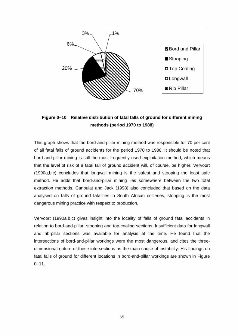
65
Figure 0–10 Relative distribution of fatal falls of ground for different mining
methods (period 1970 to 1988)
This graph shows that the bord-and-pillar mining method was responsible for 70 per cent
of all fatal falls of ground accidents for the period 1970 to 1988. It should be noted that
bord-and-pillar mining is still the most frequently used exploitation method, which means
that the level of risk of a fatal fall of ground accident will, of course, be higher. Vervoort
(1990a,b,c) concludes that longwall mining is the safest and stooping the least safe
method. He adds that bord-and-pillar mining lies somewhere between the two total
extraction methods. Canbulat and Jack (1998) also concluded that based on the data
analysed on falls of ground fatalities in South African collieries, stooping is the most
dangerous mining practice with respect to production.
Vervoort (1990a,b,c) gives insight into the locality of falls of ground fatal accidents in
relation to bord-and-pillar, stooping and top-coaling sections. Insufficient data for longwall
and rib-pillar sections was available for analysis at the time. He found that the
intersections of bord-and-pillar workings were the most dangerous, and cites the three-
dimensional nature of these intersections as the main cause of instability. His findings on
fatal falls of ground for different locations in bord-and-pillar workings are shown in Figure
0–11.
70%
20%
6%
3% 1%
Bord and Pillar
Stooping
Top Coaling
Longwall
Rib Pillar

66
Figure 0–11 Relative distribution of fatal falls of ground for different locations in
bord-and-pillar workings (period 1970 to 1988)
Figure 0–12 depicts Vervoort’s (1990a,b,c) findings on fatal falls of ground locations in
stooping sections, showing the relative distribution of each location over the period 1970
to 1988.
Figure 0–12 Relative distribution of fatal falls of ground for different locations in
stooping sections (1970 to 1988)
12%
32%
43%
13% Pillar Side
Face
Intersection
Roadway
38%
19% 19%
24% Pillar Side
Face
Intersection
Roadway
67
In stooping sections, sidewall collapses account for 38 per cent of fatalities, which
Vervoort (1990a,b,c) attributes to an increase in stress on the remaining parts of the
pillars through which sidewall failure can occur.
In the period considered by Vervoort (1990a,b,c), only one fatality occurred as a result of
a sidewall collapse, the others resulting from falls of ground in the intersections.
Mark et al. (1999b) reported that over the period 1989 to 1996, 33 deaths were the result
of retreat pillar extraction. This figure represents 25 per cent of the total 111 roof and rib
fatalities over the same period. They further reported that 45 per cent of the fatalities
related to pillar extraction occurred when the continuous miner was cutting the last lift.
1.10 Conclusions
Various pillar extraction methods are applied successfully on a worldwide front. These
methods include both methods for the secondary extraction of previously mined pillars as
well as “pillars” designed and developed for immediate extraction such as the typical rib
pillar methods.
It is critical to take note of the various constraints affecting successful pillar extraction both
during the design phase as well as in the evaluation of previously mined pillars. Although
it is well known that due to the dynamic nature of pillar extraction, and awareness of
danger involved in pillar extraction, limited study into the investigation of falls of ground
fatalities in South Africa indicated that pillar extraction is the least safe mining practice
(Vervoort [1990], Canbulat and Jack [1998]).
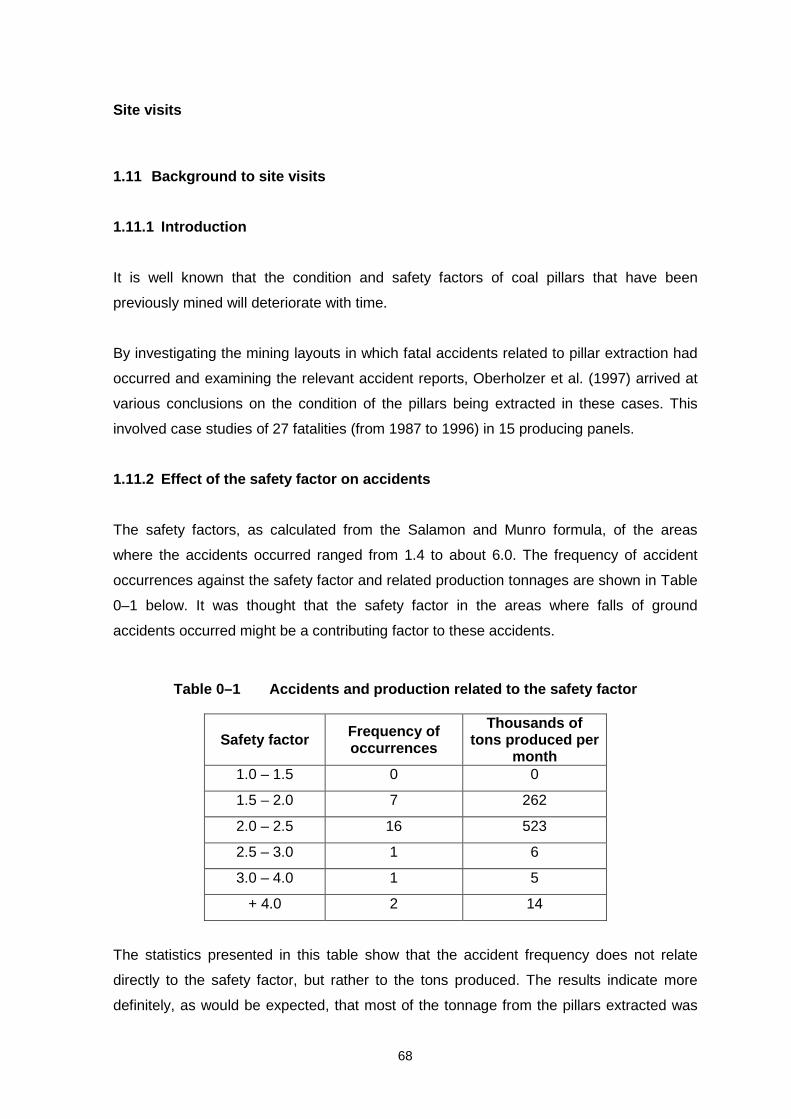
68
Site visits
1.11 Background to site visits
1.11.1 Introduction
It is well known that the condition and safety factors of coal pillars that have been
previously mined will deteriorate with time.
By investigating the mining layouts in which fatal accidents related to pillar extraction had
occurred and examining the relevant accident reports, Oberholzer et al. (1997) arrived at
various conclusions on the condition of the pillars being extracted in these cases. This
involved case studies of 27 fatalities (from 1987 to 1996) in 15 producing panels.
1.11.2 Effect of the safety factor on accidents
The safety factors, as calculated from the Salamon and Munro formula, of the areas
where the accidents occurred ranged from 1.4 to about 6.0. The frequency of accident
occurrences against the safety factor and related production tonnages are shown in Table
0–1 below. It was thought that the safety factor in the areas where falls of ground
accidents occurred might be a contributing factor to these accidents.
Table 0–1 Accidents and production related to the safety factor
Safety factor Frequency of
occurrences
Thousands of tons produced per
month 1.0 – 1.5 0 0
1.5 – 2.0 7 262
2.0 – 2.5 16 523
2.5 – 3.0 1 6
3.0 – 4.0 1 5
+ 4.0 2 14
The statistics presented in this table show that the accident frequency does not relate
directly to the safety factor, but rather to the tons produced. The results indicate more
definitely, as would be expected, that most of the tonnage from the pillars extracted was

69
mined at safety factors between 1.5 and 2.5, which was also the range within which most
of the accidents occurred. Approximately 85 per cent of the accidents occurred at safety
factors between 1.5 and 2.5 and 97 per cent of the tonnage produced were also in this
range. The accident reports indicated that 85 per cent had occurred in the area directly
related to the actual extraction operation and 15 per cent elsewhere in the section. These
dramatic figures indicate that the major fall of ground hazard is the area where the pillar
extraction is actually being done.
1.11.3 Condition of pillars in pillar-extraction sections
Pillars older than 10 years are likely to have been mined by means of conventional drill
and blast and those from more recent years by means of continuous miners of either the
drum or roadheader type.
Although the rib sides from blasting will be more uneven than those cut by continuous
miners, general pillar conditions will be influenced by the local geology and stress levels
rather than the mining method.
In the survey specific attention was given to the pillars immediately adjacent to the goaf
line as mining retreated. These pillars were the most sensitive and gave the best
indication of induced scaling due to pillar extraction.
Cases in which there was no scaling as well as cases in which there was severe scaling
were observed in panels mined by both the drill and blast method and continuous miners.
However, the severe scaling occurred where the safety factors were low. Roof conditions
and support away from the stooping line were typical of the mines in which pillar extraction
was done.
From informal discussions held with the personnel involved in pillar extraction, it was
found that the most important human factors affecting the safety aspects associated with
pillar extraction were: training, local knowledge and the discipline of the team of workers
doing the pillar extraction. In addition to the safety factor, the general condition of the area
and adequate support were of the major aspects taken into account, whereas the age of
the pillars was not of a matter of particular concern.

70
The applicable observations and information from this exercise are summarised in Table
0–2 and Table 0–3 below, indicating that old pillars with low safety factor are more prone
to scaling.
Table 0–2 Condition of pillars related to age
Condition of pillars
Age (years)
Number of panels
No scaling
Slight/ moderate scaling
Severe scaling
Tons mined/month (thousands)
0 – 1 5 3 1 1 260 1 – 3 3 2 1 - 110
3 – 10 2 2 - - 50 + 10 5 - 3 2 160 Total 15 7 5 3 580
Table 0–3 Condition of pillars related to safety factors
Condition of pillars
Safety factor
Number of panels
No scaling
Slight/ moderate scaling
Severe scaling
Tons mined/month (thousands)
1.0 – 1.5 2 - 1 1 90 1.5 – 2.0 3 - 1 2 170 2.0 – 2.5 4 2 2 - 270
+ 2.5 6 5 1 - 60 Total 15 7 5 3 590
1.12 List of sites visited
Table 0–4 lists the mines visited and shows the status of the checklists.

71
Table 0–4 List of mines and status of checklists
Mines visited Resp. Person Checklist completed
Gloria Jan du Plessis
Piet van Vuuren
Yes
Blinkpan Jan du Plessis
Piet van Vuuren
Yes
DNC Dave Hardman Yes
Tshikondeni Jan du Plessis Outstanding
Greenside Dave Hardman
Gavin Lind
Yes
New Clydesdale Dave Hardman
Gavin Lind
Yes
ZAC Conri Moolman Yes
Tavistock Dave Hardman Yes
Boschman’s
Section
Dave Hardman
Gavin Lind
Yes
New Denmark Jan du Plessis Yes
Twistdraai Jan du Plessis Yes
1.13 Purpose of site visits
The purpose of the site visits was to:
validate findings from previous research
identify current practices
evaluate probable methods for future reference.
Pillar extraction is undertaken in order to increase the amount of coal recovered from a
given in situ resource. It may be done to extend the life of a mine, in order to continue
supplying customers with a particular quality of coal, or to maintain production at a
particular level when existing development panels have encountered poor mining
conditions and there is a sudden shortage of ‘pit room’. Whatever the reason for adopting
pillar extraction, it must be done safely and profitably with a minimum amount of
disturbance to the environment.

72
As part of the Coaltech project, an evaluation of the current practices was required. For
this purpose a checklist was developed, a copy of which is given in Appendix 4.
In the checklist an attempt is made to elicit a quantification of the various constraints. The
information required can be summarised as:
• General information
• Extraction method
• Extraction sequence
• Extraction equipment
• Production rates
• Personnel employed
• Original design parameters
• Current pillar conditions and measurements
• Roof and support conditions
• Additional information
• Problems experienced with pillar extraction and solutions, if possible
• Age of pillars
• Quality
• Surface
• Underground
• Costs/revenue
• Engineering
• Safety and health
• General
• Detailed survey of the panel
• Borehole logs
• Detailed geotechnical information (slips, joints, faults, dykes, multiple seams, etc.)
• Surface information and restrictions
• Mining history (previously extracted panels).
1.14 Conclusions from site visits
Although the database was small and consequently the correlation low, the following
conclusions can nevertheless be drawn:

73
a) The initial safety factor of the pillars has a major effect on the pillar conditions
during pillar extraction, specifically near the stooping line.
b) The pillar conditions at the stooping line tend to deteriorate more rapidly as the
age of the pillars being extracted increases.
c) Mine personnel working with pillar-extraction panels do not perceive the age of the
workings as contributing to the hazard of pillar extraction.
d) About 40 per cent of the tonnage mined at the time had been produced from
panels older than three years or with a safety factor of less than 2.0.
From the discussions with and site visits to various mining groups, it became apparent
that the following mining groups practised total pillar extraction (the mines associated with
this practice are also listed below):
a) Iscor: DNC
Tshikondeni
b) Sasol: Twistdraai
Sigma
c) Duiker: Tavistock
Boschman’s Section.
It was further observed that except for the Tshikondeni Colliery and the Sasol mines, all
the mines were mining previously developed sections whose panels were not originally
designed for total extraction mining methods.
It was also apparent that the mining method employed, and especially the pillar mining
sequence, was site-specific. As such, the design and the mining methods used were
specifically adapted to suit local mining and geological conditions.
In all the feedback received it was claimed that this method of mining was as safe as or
even safer than normal bord-and-pillar development. These findings are similar to those
reported by Oberholzer et al. (1997).
It was further evident that extraction efficiency (of single pillars) is site and operator-
specific. The final extraction efficiency is normally a matter of judgement on the part of the
operator.

74
There was no difference in coal quality except in panels where high levels of oxidation
were reported.
It was reported by the mines that the cost of later pillar extraction is generally lower than
the development cost when pillar extraction follows directly after pillar development. This
aspect was not further investigated but it was determined that no provision was made for
unforeseen costs such as major roof collapses. This lower cost is most probably the result
of lower support requirements during secondary extraction. However, where extensive
clean–up of old panels has to be done along with the provision of extensive additional roof
support and the installation of support services, the cost of pillar extraction increases.
There are two distinct different approaches to the ventilation of goafed areas in this mining
operation. The primary ventilation is normally directed over the continuous miner into the
back or goafed area. The goaf is then either ventilated into bleeder roads or coursed into
return airways.
A qualitative and quantitative approach to site inspections prior to the opening of an old
mined-out bord-and-pillar section is critical. It was generally felt that detailed decision-
making about the method to be employed was only possible after a thorough in-section
evaluation of the reserves available and the prevailing mining and panel conditions had
been done.
75
Review of current mining practices
1.15 Introduction
A checklist (Appendix 4) was compiled to collect information from collieries that had
previously, or were presently practising pillar extraction using continuous miners or
roadheaders. Since the target coal regions of the Coaltech research is the Witbank
Coalfield and the Highveld Coalfields, those collieries within or adjacent to this Coalfield
have been reviewed although information was collected from more distant Coalfields.
The ten collieries from which checklists were obtained are as follows:
Greenside Colliery, Anglo Coal
New Clydesdale Colliery, Anglo Coal
Boschman’s Colliery, Duiker Mining
Arthur Taylor Colliery, Duiker Mining
Koornfontein Colliery, Gloria Shaft, Ingwe
Koornfontein Colliery, Blinkpan Shaft, Ingwe
Twistdraai Colliery, Sasol Coal
New Denmark Colliery,Anglo Coal
Durban Navigation Collieries, Iscor
Zululand Anthracite Collieries, Ingwe
For completeness the data for Durban Navigation Collieries (DNC) and Zululand
Anthracite Colliery (ZAC) has been included in the tabulations although it is realised that
factors at these sites may not be pertinent to the Witbank Coalfield region. In the case of
DNC, the greater depth of around 250 m and large pillar size of about 25 m square pillars
far exceeds what is to be expected in the Witbank Coalfield. Conditions at ZAC in the
Zululand Coalfield are also considered not to be representative of the Witbank region.
Although the data from these two collieries are included in the tabulations, reference to
them will be minimal in comparison to the other eight collieries. Data for New Denmark
Colliery has been included but this concerns the application of shortwall equipment to take
out a limited number of old pillars at a depth of 200 m and at a mining height of about
1.8 m.
Appendix 1 compares the geometry of the sites from which pillar extraction data was
obtained along with the resources used (equipment and men) and the outputs obtained.

76
Appendix 2 compares the geology and support performance/efficiency and Appendix 3
lists some of the problems associated with the pillar extraction panels together with
financial, engineering and safety performance in comparison to bord and pillar
development panels.
Checklist information covers the use of ‘full’ pillar extraction allowing the goaf to cave,
partial extraction of pillars leaving small snooks to support the goaf on a temporary basis
and checker-board extraction where alternate pillars are left to support the goaf area. In
the latter situation, mines have designed the panels so that the remaining pillars after
checker-board extraction, will not fail violently but will yield over time. Partial pillar
extraction has the advantage of not creating a goaf edge that requires breaker line
support and also can preserve the water table. Proponents of partial pillar extraction claim
that resource recovery can be as effective, if not better, than ‘full’ pillar extraction.
1.16 Range of geometrical and geological settings
Three of the checklists cover pillar extraction in the No 2 Seam of the Witbank and
Highveld Coalfields, four from the No 4 Seam and one from the No 5 Seam. For the 4-
Seam workings, the extraction height ranged between 1.8 m and 3.8 m while that in the
No 2 Seam ranged from 3.6 m to 5 m. The extraction height in the No 2 and 4 Seams was
sometimes less than the Seam height, thereby leaving coal in the roof. The No 5 Seam
pillar extraction operation took the full Seam height of 1.8 m as did the shortwall operation
at New Denmark.
Pillar width varied between 18 m and 8.5 m, depth varied between 200 m and 30 m and
the bord width ranged between 6.5 m and 7.5 m. Safety factors were generally within the
range of 1.7 to 2.1.
Panel widths ranged from about 120 m to 210 m for the bord and pillar operations which,
when compared to the depths of the panels, results in a width/depth ratio variation from
over 6 to just less than 1. Apart from the shortwall at New Denmark colliery, all pillar
extraction operations made use of either a drum-type continuous miner or a roadheader.
Output per month varied between 19 000 ton in a low Seam height operation and 50 000
ton in a thick Seam operation and output per man per month varied between 1 055 ton to
4 167 ton.

77
1.17 Geology and support effectiveness
Of the ten different collieries, only DNC has a significant thickness of dolerite in the
superincumbent strata which could limit the extent of caving.
The immediate roof strata is typical of local coal seams, being mainly sandstone, although
some shale or shaley-sandstone is also reported. Where a mine does not take the full
seam thickness, generally for quality control reasons, the immediate roof becomes coal.
Floor strata is generally sandstone although some occurrence of shale, shaley-sandstone
and siltstone is also reported for some mines.
Length of installed roofbolts ranges between 0.5 to 1.9 m, with 1.2 and 1.5 m long bolts
being the most favoured. In some cases, 5 m long cable anchors are also used to support
specific areas by some of the mines. Generally, roof competence is reported to be good to
excellent by most of the mines except in the vicinity of slips and faults. The majority of
mines do not have problems with support failures and current support conditions are
reported to be good. Similarly, pillar punching into the floor is not foreseen as a problem
neither is pillar fracturing, except at the two KwaZulu-Natal collieries.
From personal visits to pillar extraction sites, the main support problem area is the
intersections, particularly adjacent to the pillar being extracted in a ‘full’ extraction panel.
That is to say in a region of high stress. There is also a high risk of sidewall collapses. It is
at this intersection where continuous miners are most likely to be buried by a fall of roof.
Bord widths are quoted above to vary between 6.5 m and 7.5 m and, although these
widths may be stable in bord and pillar development panels, the additional induced stress
from pillar extraction can result in intersection collapse. This will be made worse where old
panels are being extracted and pillar spalling may have caused an increase in bord
widths, particularly if the panels were originally formed by drill and blast methods.
1.18 Surface and underground environmental concerns
Where mines are practising ‘full’ pillar extraction, surface subsidence occurs to an amount
reported to be from about 33 per cent of the extracted seam height at New Clydesdale
Colliery to almost 80 per cent at Boschman’s Colliery. In the case of those collieries
applying a checker-board pillar recovery method surface subsidence is either minimal or

78
does not occur at all. There are some inconsistencies with regard to the effect of pillar
extraction on the water table. It is to be expected that where mines are practising ‘full’
pillar extraction and experiencing subsidence then this would also affect the water table.
Conversely, where the checker-board method is in use and caving of the upper strata is
absent then the water table should remain generally unaffected. This is not always the
case as reported by the mines. In these cases, the height at which the groundwater table
occurs in comparison to coal horizon and mining thickness play a significant role.
Of the ten mines, only one, DNC, reported spontaneous combustion to be a problem and
only three mines, DNC, Twistdraai and New Denmark reported methane to be a problem.
Twistdraai, New Denmark and Boschman’s Collieries reported problems with airflow
through and over the goaf.
1.19 Variation in coal quality and size
Only two collieries, Twistdraai and New Denmark, reported that there was a change in the
coal quality. For Twistdraai it was indicated that there was less contamination but the
cause for this is not stated. (It was found in many cases of “full” pillar extraction, that
people tend to leave coal in the roof and floor to increase speed of extraction.) The
opposite occurred at New Denmark where contamination from cutting in the floor resulted
in an increase in stone in the run-of-mine product.
Most of the mines report a larger product size during pillar recovery operations but only
one mine, Gloria shaft, quantified the increase as a 5 per cent increase in larger coal. The
increase in coal size is also supported by other remarks that some mines make with
regard to easier cutting conditions and lower pick costs (more tons per pick). All of these
factors support a more efficient cutting process during pillar recovery in comparison to
pillar development.
1.20 Machine efficiency and machine modifications
The majority of the mines report no difference in machine availability during pillar recovery
operations compared to pillar development. However, DNC report lower availability and
Greenside and NCC report better availability. In the case of DNC reduced availability is
due to delays caused in repairing machines after being damaged by roof collapses. For
Greenside and NCC better availability is reported to be due to more attention being given

79
to machine maintenance and repair because of the need to remove pillars quickly with as
little delay as possible.
Most mines make some machine modifications in order to better facilitate pillar recovery.
Modifications include:
• removal of the dust scrubber in case it gets damaged in a roof collapse,
• provision of protective cage and high speed tram on shuttle cars,
• provision of cable arm and automatic reverse on the continuous miner,
• modification to continuous miner traction motors so that they can be operated via a
shuttle car cable in case of damage to the continuous miner cable.
1.21 Section safety
Contrary to historical beliefs, all mines report no difference in safety performance in pillar
recovery sections when compared to pillar development sections. Two mines quote a
better safety record in pillar recovery sections due to a greater awareness by the
employees of the need to be alert at all times. No statistical results are available to
confirm this finding, but the checklist answers were compiled/provided by mine managers
or section managers from their own knowledge of pillar extraction practice.
1.22 Costs
It is realised that mines do costing in different ways and some costs quoted by some of
the mines cannot be directly compared to each other. However, all mines except
Boschman’s Colliery and New Denmark Colliery, report that pillar recovery operations are
cheaper than pillar development operations. The reasons given for this are lower pick
costs (easier cutting) and lower support costs. Boschman’s Colliery report a higher cost
for pillar recovery because of the additional cost of rehabilitating the old panel in terms of
re-supporting, cleaning up and re-stone dusting. New Denmark’s higher cost per ton when
removing pillars, as opposed to conventional shortwall, is due to a reduced tonnage of
coal per metre run of face length because of the presence of roadways.

80
1.23 Method of pillar removal
A comprehensive literature survey, questionnaires sent to Industry and numerous site
visits both to local and international mining operations confirmed the application of only
old, known methods of pillar extraction.
Various variations of these methods are however practiced with great success.
The most recent development in the field of pillar extraction identified during the research
is the so-called Nevid-method developed by Sasol Coal and practiced extensively with
great success. This method resembles a method practices by Ermelo Mines Services
during 1984 in the extraction of small pillars (± 9.5 m pillars). The general trend in pillar
extraction with continuous miners has moved completely away from the traditional 45 °
stooping line to a 90 ° stooping line.
A number of subsequent industry workshops also did not produce any new innovative
ideas for further development.
The various successful methods used or approaches to pillar extraction can be grouped
into three distinct categories based on current application:
• Small to medium pillars (angled cuts)
This method entails a number of almost diagonal cuts through the pillar from the safety of
two solid pillars. Small snooks are left on the outside of the pillar with a reasonably large
snook or “rib” protecting the intersection from where the cuts are taken. Boschman’s
Colliery and Auther Taylor Colliery are using this method successfully on pillars from
approximately 10 m up.
• Medium to large pillars (split and fender)
Methods in this category stems primarily from the development of the rib pillar extraction
method. In this method, normal predeveloped pillars, both square and rectangular, are
split in ribs by cutting through them at right angles. The ribs are then mined with a series
of angled cuts similar to the rib pillar extraction methods.

81
Collieries such as Sigma, Brandspruit, Middelbult, Twistdraai, Bosjesspruit, Longridge,
Springfield and DNC have successfully applied this approach in pillars from 18 m and
larger. Currently Middelbult Colliery is still applying this method.
• Medium to large pillars (angled cuts)
Sasol Coal developed the so-called Nevid method at its Bosjesspruit Colliery for pillar
extraction in horizontally stressed environments. The method is based on carefully
planned angled cuts from two directions through the pillar, leaving snooks on the outside.
A strong final rib is left protecting the intersection from which mining takes place.
Currently Brandspruit, Twistdraai and Bosjesspruit Collieries are practising this method
with overwhelming success on pillars from 24 m upwards.
1.23.1 Small to medium pillars (angled cut method)
Introduction
A number of collieries has in the past experimented with, and applied pillar, extraction on
small pillar ranging from 9.5 m upwards. These include Longridge, Ermelo Mines,
Greenside and Sigma. The overall approach was to take a number of diagonal cuts
through the pillar. In all of them, either the first or the last cut attempted to remove the
diagonal rib (left from the intersection from where cutting takes place. The focus appeared
to be maximum recovery of the pillar rather than controlled goafing and intersection
stability.
Both Boschman’s Colliery and Auther Taylor Colliery are currently practising a similar
approach to pillar extraction with the exception that the critical intersection is supported by
means of a predetermined rib or snook along the diagonal. Pillar extraction has been
practised as shallow as 30 m and at safety factors as low as 1.6. The method is applied
on pillars of 4 to 5 years old, developed through conventional drilling and blasting
methods.
Production rates of approximately 50,000 tons per month are achieved with this method.

82
Mining method and cutting sequence
Contrary to the traditional way of pillar extraction (1980’s), pillars are extracted in a
straight line and not on a 45° stooping line. The standard practice is to extract pillars from
left to right but it has been done successfully the other way round as well. Typical 9 – road
sections developed by drill and blast methods 4 to 5 years ago are mined successfully
with this method. All pillars, including the barrier pillar between adjoining panels are
removed.
Three single cuts are taken through the pillar as depicted in Figure 0–1 (b). This ensures
always mining away from the goafed area as well as the safe positioning of the continuous
miner operator and cable handler.
The angled cuts through the pillar eases continuous miner movement and allow for rapid
retreat should goafing threatens. The ease of cutting also provides for consistent snook
sizes, depending on pillar geometry.
Strata control and roof support
At Boschman’s Colliery, the whole panel requires re-supporting as the original roofbolts
have been installed and tensioned by hand. These bolts were 0.7 m mechanical anchor
bolts. The new support consists of 1.5 m point anchor resin bolts spaced at 2 bolts per
row every 2 m.
Roofbolt breaker lines are used throughout as indicated in Figure 0–1 (a) and consists of
1.2 m point anchor resin bolts spaced 1 m apart in the row and rows 1 m apart. A timber
prop (policeman) is installed as indicated on completion of cut No 2 for early warning of
roof movement. Two-timer props per roofbolt breaker line are also installed as a
policemen.
A diagonal rib starting 1 m on either side of the corner from where cutting is done is left to
protect the intersection. This is critical in ensuring maximum protection of the continuous
miner during and until after cut No 3. The rib thins out towards the goaf side to increase
percentage extraction and to ensure proper goafing which, in shallow workings can cause
serious problems.

83
No mobile breaker line supports are used. A continuous miner extractor is provided to
ensure quick retrieval of the continuous miner should the situation warrants.
At shallow depths of down to 30 m, surface subsidence is quite severe and causes major
cracks and undulations on surface. Future pillar extraction at Boschman’s will
consequently be limited to depth below surface of 50 m and more. All pillars including the
barrier pillars are removed in order to increase overall extraction and to obtain smother
surface subsidence profile.
Ventilation
Ventilation is coursed through the section from right to left by means of line brattices as
depicted in Figure 0–1 (a). A jet-fan is used in the last through road to assist in the
coursing of the ventilation.
The small pillars and resulting short cutting distances result in excellent ventilation as well
as low dust levels.
No bleeder roads are left, as the occurrence of methane is very low.
Percentage extraction
On typical 10 m pillars, the theoretical percentage extraction amounts to ± 75 per cent,
resulting in an overall extraction of 85 per cent should barrier pillars be left and 90 per
cent where barrier pillars are also extracted.

84
Figure 0–1 (a) Extraction of medium to large pillars with split and fender method -
mining sequence and ventilation layout with half bleeder road (b) Extraction of
small pillars with angled cut method - mining sequence and ventilation layout with
no bleeder road

85
1.23.2 Medium to large pillars (split and fender method)
Introduction
This method has developed over a number of years from optimisation of the typical rib-
pillar extraction methods. One of the major problems with rib-pillar extraction is related to
the varying production rate. Production during the initial development stage (2 and 3 road
development) as well as with the development of the ribs is relatively low. This is a result
of long tramming, shuttle car change-out time, limited tramming roads and the
cutting/roofbolting interaction. During the extraction of the rib (fender) production is higher,
but still constrained by long and limited shuttle car tramming roads.
Various collieries have been involved in the development of this method over a number of
years. The common principle is the splitting of a pillar into 2 to 3 fenders (ribs) which are
extracted similar to rib-pillar mining.
Production rates of approximately 60,000 tons per month are achieved with this method.
Mining method and cutting sequence
In this method, panels are developed with 7 to 9 roads at pillar centres of 24 m and more,
resulting in pillar sizes of approximately 18 m. Pillar geometry, in terms of being able to be
split into fenders (ribs) of approximately 6 m, is the main criterion for pillar design,
provided the safety factor does not go below 1.6. Square pillars are common practice,
although rectangular pillars have also been successfully mined.
Pillar centres must preferably be multiples of 12 to 14 m in at least on direction to allow for
fenders of approximately 6 m after splitting of the pillar.
Once the end of a panel is reached, pillar extraction commences, with pillars being
extracted from left to right in a straight line, as depicted in Figure 0–2 (a).
Pillars are normally split lengthwise in the direction of the panel, leaving 2 to 3 fenders of
approximately 6 m as depicted in Figure 0–2 (b).
Once the fenders are created, they are extracted by taking a number of angled cuts
through them as depicted in Figure 0–2 (b), similar to rib-pillar mining. This cutting

86
sequence is ideally suited to remote controlled continuous miners as it affords the
continuous miner operator maximum visibility of the continuous miner from a safe location
i.e. protected by solid pillars.
Strata control and roof support
During pillar extraction roofbolt breaker lines are installed as depicted in Figure 0–2 (b)
consisting of a double row of resin bolts spaced at 1 m intervals.
During the splitting of the pillars into fenders, it is important to keep the split as narrow as
possible, without inhibiting the manoeuvrability of the continuous miner when extracting
the fenders. No roofbolts are installed in the split, provided the maximum distance cut
does not exceed the mine Code of Practice for Roof support requirements and both
shuttlecars and continuous miners (except remote controlled continuous miners) are
equipped with adequately design canopies.
The split must also be at 90 ° to ensure fenders of consistent dimensions.
If not cut at 90 ° it may result in poor roof control and inconsistent snooks (too large) left
especially on the wide end of the fender. This may result in goafing problems.
A large snook is left of each fender closest to the intersection from where pillar extraction
is done to provide maximum protection to that intersection. Attempts to extract this last
snook have resulted in many continuous miners being buried in the goaf.
Mobile breaker line supports were developed and used at Sasol Coal many years ago.
The use of these was discontinued due to their tendency to get stuck in the goaf as well
as other logistical problems. The development of roobolt breaker lines as currently
practised at most pillar extraction operations, resulted in a much smoother and more
productive pillar extraction operation.
Ventilation
The ventilation is coursed through the section from right to left as depicted in Figure 0–
2 (a).

87
During the splitting of the pillar either a jet-fan or a line brattice is required to ventilate the
heading and remove gas and dust, as the cut is generally driven more than 10 m past the
last through road.
Depending on the methane liberation properties of the coal seam and the overlying strata,
the establishment and maintenance of a bleeder road on one side of or fully around the
panel/panels to be extracted is required. Various incidents of methane ignitions have
already occurred at the goaf edge or inside the goaf.
Percentage extraction
On typical 18 m pillars, the percentage extraction amounts to 60 per cent of each
individual pillar. This is primarily the result of spillage from the continuous miner into
previous cuts, inconsistent snook sizes and the size of the final snook left to protect the
intersection. Overall extraction varies from a low of 66 per cent at 100 m below surface, if
barrier pillars are left intact and a full bleeder road is required around each individual
panel, to approximately 80 per cent if barrier pillars are mined and bleeder roads are not
required.

88
Figure 0–2 (a) Extraction of small pillars with angled cuts - cutting sequence (b)
Extraction of medium to large pillars with split and fender method - cutting
sequence

89
1.23.3 Medium to large pillars (Nevid method)
Introduction
Sasol Coal developed the Nevid method of pillar extraction at their Bosjesspruit Colliery to
overcome the majority of problems experienced with other pillar extraction methods in
horizontally stressed areas. The Nevid method of pillar extraction can be classified as a
partial pillar extraction method. In fact, virtually all pillar extraction methods are partial
pillar extraction methods as snooks of varying shapes and sizes are left behind to protect
people and equipment and to control the goafing of the immediate roof.
The name “Nevid” originated from the names of the two people responsible for the
development of the method, i.e. Neels Joubert and David Postma at Sasol Coal. The
method is fairly adaptable and can be applied in virtually all circumstances.
Various problems are continuously encountered with the conventional approach to pillar
extraction. These are primarily resulting from horizontal stresses and the inconsistency of
snooks left behind in the goaf area. The latter is caused by the difficulty of cutting at right
angles to existing roadways or new lifts taken. The number of lifts taken and the direction
in which they are taken are to a large extend left at the discretion of the continuous miner
operator and section miner.
Specific problems resulting from the above include: -
• poor ventilation
• massive and unpredictable goaf behavior
• burial of continuous miners
• accidents
• airblasts resulting in damage to ventilation structures and injuries
• variable and unquantifiable extraction of reserves
• people exposed to unsupported roof and
• variable production rates.
The Nevid method was developed to overcome most of these problems through easy
control over cutting sequence and specifically cutting direction
90
The typical layout for the Nevid method of pillar extraction provides for a 7-road layout
with 28 meter center distances, although centers can be reduced to 24 meters with the
same pillar extraction cutting sequence as depicted in annexure 3.
Mining method and cutting sequence in Nevid method
At the start of a new panel, which is after completion of the panel development, the top
middle pillars are split as depicted in Figure 0–3 in order to increase overall extraction of
the coal. They are not mined fully to prevent the goaf from running into the ventilation
bleeder road around the panel. Two double lifts are cut through the pillar in the top right
corner similar to the cutting of all pillars next to the right barrier. These pillars with only two
lifts cut are left to establish the rest of the bleeder road around the panel.
Cutting then follows he sequence as depicted in Figure 0–3, starting from left and always
working to the right. All cuts are taken a 45-degree angle to the centerline of the original
development. Cutting direction lines are in all cases installed on the roof on the right-hand
side of the first lift (“a”-cut) to be made by the continuous miner as depicted in Figure 0–5.
This ensures that the continuous miner operator can always easily control the cutting
direction from a safe position. The “a” lift is always cut before the “b” lift. As the “a” lift is
always shorter than the “b” lift, it ensures breaking through into the return air side of the
pillar in the shortest possible time. This establishes through ventilation and improves dust
removal and methane drainage. The “b” lift is always taken right up against the most solid
side of the remaining portion of the pillar being mined. This ensures maximum protection
to the continuous miner.
Strata control in Nevid method
The primary success of the Nevid method stems from two specific aspects: -
-The specific cutting sequence and
-The consistency of snooks left.
The cutting sequence of each individual pillar as well as the extraction sequence of
subsequent pillars affords maximum protection to the continuous miner at all times. The
continuous miner always has a solid pillar or the strongest possible remaining snook
adjacent to it. The 45 degree cutting angle also provides for the fastest possible retreat of
the continuous miner should goafing conditions requires such action.

91
Each individual pillar is marked off in terms of cutting position and cutting direction lines
prior to any cutting according to a predetermined pillar design. The 45 degree cutting
angle allows for much easier cutting and direction control. It further improves the vision
from the continuous miner operator for better control of the continuous without exposing
him to high risk areas. Strict adherence to this layout ensures consistency of snooks left
behind. This provides for a fairly consistent and almost predictable goafing pattern.
The goafing generally follows the extraction of pillars by one row of pillars. The
consistency and size of the snooks ensure a steady and moderate goafing behind mining.
Should the goaf however hang up for more than two rows of pillars, a stopper pillar is left
on the third row as depicted in Figure 0–3. This is done to counter violent goafs and
reduce the risks of potential air blasts. Each goafing situation is evaluated individually and
no stopper pillars are left in the event of no hanging up of the goaf.
In the event of mining on the weak side of joints, great care must be taken. This includes
the cutting of single lifts or even no cutting at all.
Critical dimensions for the positioning of the various cuts are indicated in Figure 0–5 for a
typical 28 meter center pillar layout. This plays a critical role in the strength of the
remaining snooks and subsequent goaf development and is essential to the success of
this method. Different pillar sizes may require different distances and even possible
variation in the taking of single or multiple lifts through the pillars.
Roofbolt breaker lines are used throughout as they allow ease of installation, may for part
of the initial systematic roofbolting during development and are provided at low cost. They
have further proved to provide sufficient support for various pillar extraction methods in
South Africa. Roofbolt breaker lines are installed in all positions as demarcated in Figure
0–5.
Warning sticks or “policemen” are installed in the positions as shown in Figure 0–5.
Installation of warning sticks must be completed prior to commencing with cutting on the
adjacent “a” cut. These are required as early warning device for any potential snook
failure and/or roof movement.

92
Ventilation in Nevid method
Two critical ventilation aspects require attention in all types of pillar extraction, both of
which are better addressed in the Nevid method than in other methods. These are;
bleeding methane out of the goaf, and taking dust and possibly methane away from the
working area. This provides for a much healthier and safer working environment.
The general ventilation layout is such that most intake air is coursed directly over and/or
behind the continuous miner straight into the mined out zone. From there it goes directly
into the return airway, which is also the bleeder road. This ensures that both methane and
coal dust are continuously taken away from the people and working area directly into the
return airway. During all cutting the continuous miner operator is positioned on the intake
side of the continuous miner and not exposed to any dust. It is only during the first lifts,
marked “a”, in Figure 0–5 that the continuous miner is not cutting in through ventilation in
the sense that air is moving past the continuous miner instead of directly over it as in the
“b” lift. This is however always the shortest lift and results in the quickest holing through
into the mined out zone and establishing through ventilation.
After completion of cut 1, a ventilation curtain is installed in position “A” as indicated on
Figure 0–4. This ensures maximum ventilation flow past cut 2. On completion of cut 2, the
curtain at position “B” is removed and installed in position “C” before cutting 3 and 4. After
completion of cut 4, the curtain at position “C” is removed and installed at position “D”.
This cycle is repeated until cut 14, after which the curtain at position “E” is moved to
position “F” and the curtain at position “A” is removed.
Unlike most other pillar extraction methods, the last row of pillars extracted remains open
up to the mining of the next row, which allows for proper ventilation throughout the cycle.
This is to a large extent as a result of the design of the snooks left and the subsequent
consistent goafing.

93
Figure 0–3 Nevid – pillar extraction cutting sequence
DIRECTION LINES AT
45 DEGREE ANGLE
LINES
4b
4a
3a
INSTALL CUTTING
1a1b
2b
2a
±5m
±6m
±6m
±5m
5a
GO
AF
ED
AR
EA
±2m
±2m
3b 5b
7a
7b
ROOFBOLT BREAKER
CRITICAL
DIMENSIONS
WARNING
STICKS

94
Figure 0–4 Nevid ventilation layout
C
A D
GOAF AREA
2
31
B
4
Stopper
Pillar

95
Figure 0–5 Nevid stooping cycle
1.23.4 Conclusions
Pillar extraction takes many forms and mines have adopted methods of removing
individual pillars to suit their particular needs. In ‘traditional’ stooping, it was recommended
practice to remove or destroy all snooks in order to allow the goaf to cave thereby
relieving the stress on the caving pillar line. Many of the pillar extraction methods now
used deliberately leave pre-designed snooks that prevent immediate caving but will crush
over time. Advantages of these methods are:
• the absence of a caving line, thus removing an area of high risk,
• immediate water table disturbances, and
• elimination of the problems/dangers associated with goaf ‘hang-ups’ and sudden
goaf collapses.
12
14
101 13
112
4
8
93 7
5
6
GOAF AREA
Stopper
Pillar

96
• Improved ventilation flows and methane drainage.
One major disadvantage of keeping up the goaf by the use of pre-designed snooks or by
the use of checker-board mining is the uncertainty of when the snooks or remaining pillars
are going to crush and allow the overburden strata to settle.
Contrary to previously held views, mines now do not believe that pillar extraction is a less
safe method than pillar development. This may be because pillar extraction is now done
by continuous miner, often by means of remote control, and also that the incorporation of
section employees in more risk assessment procedures has introduced a greater
awareness amongst the underground operators of the inherent dangers in pillar
extraction. Also, more use is now made of ‘partial’ pillar recovery and checker-board
systems where the formation of a goaf edge is prevented, thereby removing a hazardous
area from the system.
The cost of pillar extraction in comparison to pillar development is reported to be higher by
some mines but lower by others. Much depends on a mine’s costing procedures and
whether pillar extraction follows directly after pillar development or whether old panels
have to be rehabilitated.
Pillar extraction by means of shortwall equipment has been done successfully but a
particular problem can be the rate of retreat through the pillars. Over a face length of say
90 m made up of 4 fifteen metre square pillars and 5 six metre wide bords, coal is present
over only two thirds of the shortwall face length and the other third is ‘air’. Careful
consideration must be given to the logistics of utilising what is considered to be a highly
capital intensive method for the recovery of pillars.
The recovery of old pillars by underground pillar extraction has been shown to be feasible
in the No 4 Seam and the No 2 Seam in the Witbank Coalfield. Experience is being
gained which should be beneficial to the industry in the wider application of pillar
extraction to other parts of the Coalfield where suitable reserves may be found.

97
Application of “Nevid” pillar extraction method at shallow depth
1.24 Introduction
The NEVID method is a way of stooping pillars commonly employed in SASOL coal
mines. Although, it has been identified as one of the best methods in pillar extraction,
current design specifications for the method are specific to depth below surface of
approximately 150 m, due to pillar size requirements. Nevid method has been practiced at
shallower depths with smaller pillar sizes, which indicated that it was not successful due to
great size of snooks left behind, which did not fail and prevented the goaf taking place in
the panel. This resulted in great distances of overhangs, which was a great danger to
work force underground.
The aim of this investigation is to determine the optimal controlling dimensions and lift
width for stooping at various depths.
1.25 Methodology
The basic NEVID sequence and controlling dimensions for a depth of 160 m are
presented in Figure 0–1. Note that the three dimensions indicated and the width of the lifts
completely control the geometry and area of the snooks. Also note that the lifts in the
diagram are 3.6 m wide. Two lifts are cut (a and b), resulting in a total lift width of 7.2 m.
To avoid confusion, “lift width” will refer to the total width of the cut (a + b).

98
Figure 0–1 Controlling dimensions and cut sequence
The situation at 160 m depth is used as a reference solution for snook geometry. At this
depth, the intact pillars have a safety factor of 2.0. The safety factor for the stooped pillars
is calculated as follows:
The effective width of the stooped pillar is calculated using Wagner’s (19) approximation:
Q
Aweff
4=
Where A is the total area of the snooks left from a single pillar and Q is the total
circumference of the snooks. This effective width is used to calculate the strength of all
the snooks using Salamon’s formula:
66.0
46.012.7
h
wStrength
eff=
Where h is the seam thickness. The load on the pillar is calculated from tributary area
theory:
A
HCLoad
2025.0=

99
Where H is the depth below surface and C is the centre-to-centre distance. The safety
factor is then calculated as:
Load
StrengthSF =
For the suggested NEVID geometry, the total snook area (A) is 140.9 m2 and the total
snook circumference (Q) is 96.7 m. This gives an effective pillar width of 5.83 m and a
resultant safety factor of 0.35.
The calculated safety factor is used as a design criterion. The aim is now to determine the
controlling dimensions and lift width for a variety of depths. Firstly, the pillar width for an
intact safety factor of 2.0 is calculated using Salamon’s formula with correction for
continuous miner operation. The pillar widths for a safety factor of 2.0 is presented in
Table 0–1.
Table 0–1 Pillar widths required for a SF of 2.0
Depth [m] Pillar load [MPa] Pillar strength [MPa] Pillar width [m]
160 7.4 13.8 20.8
140 7.02 12.9 17.3
120 6.63 12.04 14.8
100 6.28 11.06 12.3
80 5.92 10.06 10
The controlling dimensions and snooks are labelled in Figure 0–2.

100
cb
ctr
ctl
lw
lw
1 2
3
4
Figure 0–2 Geometry of Nevid method
The geometries and lift widths are varied for each depth until a stooped pillar safety factor
of 0.35 is obtained.

101
1.26 Results
The extraction dimensions, lift widths and safety factors for NEVID pillars at various
depths are presented in Table 0–2.
Table 0–2 Dimensions for stooping at various depths
Depth ctr ctl cb lw A Q SF
160 6.0 2.0 5.0 7.2 140.9 96.7 0.35
140 5.0 3.0 5.0 6.0 107.5 84.6 0.37
120 4.0 2.0 4.0 5.0 78.7 77.1 0.36
100 3.0 2.5 3.0 4.5 53.0 59.1 0.35
80 2.4 2.4 2.5 3.6 36.0 47.5 0.35

102
Technical factors of constraint
1.27 Introduction
Pillar extraction, or stooping, has been practised for many years in South African collieries
as a means of increasing the percentage extraction from in situ coal reserves. Over the
years of its application, there have been many variations of the pillar-extraction method,
some of which have proved more successful than others.
In pillar extraction, panels in a bord-and-pillar mining layout are used in which many pillars
are created but only extracted at some later date as the panel must be developed
completely before pillar extraction can commence. There are two basic approaches to
pillar extraction. Firstly, the extraction of pillars in old workings where little or no account
was taken of secondary extraction during the initial panel and pillar design, and secondly,
the extraction of pillars in panels designed specifically for pillar extraction.
This report concentrates mainly on panels where the pillars were not originally designed to
be extracted.
1.28 Critical factors in pillar extraction
Successful pillar extraction is a function of many parameters, and these parameters can
be divided into two groups: controllable and uncontrollable. Unfortunately (in South Africa)
because primary extraction was not done with a view to later pillar extraction, many of the
controllable parameters in primary extraction become uncontrollable parameters in
secondary extraction. These parameters include panel width, pillar width, bord width,
mining height, pillar geometry and age of pillars.
In secondary pillar extraction, the controllable parameters are those that determine the
mining layout and sequence. These parameters are:
• Overall mining direction
• Direction of splitting
• Sequence of fender extraction
• Snook size
• Extraction technique (full extraction or partial extraction), which determines the
surface stability
• Number of seams mined.

103
The uncontrollable parameters are:
• Panel width
• Pillar width
• Bord width
• Mining height
• Depth below surface
• Geology, including overburden and interburden strata
• Caving mechanism
• Amount of scaling
• Presence, intensity of structures
• Existing roof conditions.
The effect of the above-mentioned parameters is summarised below.
1.28.1 Controllable parameters
Overall direction
It is well known that the direction of stooping should always start on the side closest to the
previously mined panel and then mine away from it, and that mining between two goafed
panels should be avoided as far as possible. If both sides of the panel are goafed, then
extraction should be from the oldest panel towards the youngest.
The direction of extraction should always be consistent. The reason for this is that during
the process of extracting a pillar, load is distributed to the surrounding unmined pillars.
These cause micro-cracks to develop in the roof and the surrounding pillars.
The micro-cracks follow the same pattern as the stress contours. If the direction of
stooping is changed, the directions of the stress contours will also change; implying that a
new set of micro-cracks criss-crossing the ones that already exist will develop.

104
Direction of splitting
Pillars should always be split in the direction of the overall advance, i.e. into the main goaf
and not parallel to it. The reason for this is that the main fractures in the pillar develop
parallel to the goaf. If a pillar is split parallel to the goaf, the fender (one of the small pillars
in each side of the pillar after it is split) closest to the goaf will be subjected to higher
stresses and hence will be weakened by the fractures created.
Sequence of fender extraction
The fenders should always be extracted from the goaf to the solid.
Snook size
In pillar extraction, the aim is to remove all pillars completely. However, for various
reasons this is always difficult to achieve. Snooks or even whole pillars will be left behind.
Therefore, the snooks of the 'correct size' should be left to protect the pillars, control the
stresses on the pillars to be extracted and prevent premature goafing of the immediate
area.
Extraction technique
It is sometimes necessary and desirable to do partial high extraction mining, either by
extracting pillars partially or by extracting some pillars completely and leaving some in
situ. The aim of the partial high extraction is to minimise the disturbance to the overlying
strata.
The design principles for partial high extraction methods are complicated. The stiffness of
the pillars and the overburden strata should be determined. The partial high extraction
layouts will be safe (meaning that the failure will be in a controlled manner) for as long as
the stiffness of the system is greater than the stiffness of the pillars.
In very broad terms, partial high extraction at higher mining heights is predominantly
controlled by restricting panel widths, thereby protecting the overburden beams from

105
failure. At lower mining heights, the ratio of pillar width to height can more easily be
brought into the range of non-violent failure. The panel width then becomes less
important.
These considerations indicate that, in practice, it is more efficient at lower mining heights
to opt for complete extraction of some pillars, leaving others in situ, and at higher mining
heights it is more efficient to split all the pillars, but to restrict the panel width.
Number of seams mined
Many collieries in South Africa contain more than one seam that is economical to mine. If
the seams are in close proximity, the mining of one seam may affect the subsequent
mining of another seam due to factors such as parting failure, punching, subsidence and
stress concentrations, which can result in difficult mining conditions.
Marketing constraints and coal quality have meant that from a strata control point of view
the ideal sequence of mining in a descending order has been difficult to achieve.
In the Witbank area multi-seam bord-and-pillar mining is common. In Natal as many as
four or five superincumbent seams have been exploited. Since the area produces high-
grade anthracite and coking coal, high extraction methods are common. Coal reserves are
usually limited and it is quite common to mine in areas that have been previously
undermined or overmined.
Several combinations of methods for mining multiple seams have been tried. Table 0–1
shows the potential safety hazards associated with different multi-seam mining sequences
and extraction methods (Hill, 1994).

106
Table 0–1 Potential safety hazards in multi-seam mining layouts (after Hill, 1994)
Method of mining Upper seam
Lower seam
Safety hazard
B&P B&P Spalling on pillars and parting collapse if P is thin and there is no superimposition
PE (2) B&P (1) Roof falls in L seam, parting collapse if P is thin B&P (2) HE (1) Tensile zones and spalling in U seam when mining over goaf/solid boundary, floor collapse over incomplete goafs. High safety risk if
P/h ratio is low Remnant Pillar (1)
B&P (2) Intersection collapse in L seam when mining under remnant
PE (1) PE (1) Simultaneous mining in both seams - roof falls in L seam HE (1) HE(2) Preferred method of mining except where there are remnant
pillars and water L = lower U = upper P = parting thickness PE = pillar extraction B&P = bord and pillar HE = high extraction
High extraction over bord-and-pillar workings
In any high extraction method, abutment stresses will be produced around the extraction
panel. These abutment stresses are transferred above and below the plane of the
workings into the surrounding strata. Where there is a bord-and-pillar layout in a lower
seam, deterioration of these workings may occur. Subsequent pillar extraction of the lower
seam pillars or use of the workings as travelling ways may be jeopardised as a
consequence of overmining.
Overmining will change the stress distribution on the lower seam workings. As the
abutment passes overhead, the pillars will experience an increase in load followed by
considerable destressing. As goafing and settlement continue in the top seam, the lower
seam pillars will be reloaded. The main factors affecting lower seam stability are:
• parting distance
• caving mechanism taking place in the extraction area
• stress distribution.
Increased parting distance will dissipate the effect of the abutment stress being
transferred to the lower seam pillars. As the parting distance increases, the change in

107
pillar load on the lower seam pillars will be less pronounced since the abutment load will
be spread over more pillars.

108
Mining over goafs
Upper seam reserves have been written off in the past by operators who assume that they
have been destroyed due to high extraction having taken place previously in the lower
seam. However, several collieries in Kwazulu/Natal have successfully mined seams that
have been undermined.
There are four characteristics of this type of mining:
i) Caving of the upper strata creates fracturing due to subsidence.
ii) Remnant pillars in the lower seam cause differential subsidence to occur. This
creates areas of instability due to tensile zones over the pillar-goaf boundary.
iii) Remnant pillars cause stress concentrations, which will be transferred to the
upper seam workings. This stress may be observed as pillar spalling or floor
heave.
iv) Areas over incomplete goafs may be destressed.
Mining conditions in the upper seam will therefore depend on a number of factors.
• Type of strata
The presence of a massive rigid layer in the overlying strata has the effect of
dampening stress transfer and immediate subsidence from lower seam mining.
Upper seam conditions can be expected to be poorer if the parting consists of
shales compared with stronger sandstones. Disturbance of an upper seam has
been showed to be less in the USA, where the lower mined out seam was
overlain by a fairly thick shale bed which was, in turn, overlain by a strong
sandstone bed (Stemple, 1956).
• Parting thickness
The thicker the parting the less damage will occur. Stress from lower seam
remnants can however be transferred over large vertical distances.
• Seam thickness
It is recognized that the vertical extent of any disturbances will depend on the
extraction height of the lower seam.

109
• Time interval
It is generally recognized that the longer the time span between lower seam
mining and upper seam mining, the better will be the conditions in the upper
seam since equilibrium will have been achieved. Roof conditions will usually be
better on a stable floor than on one which is subsiding.
• System of mining
Where the mining of the lower seam has been complete, conditions are usually
better than when incomplete mining has taken place since remnant pillars are
minimal and subsidence profiles more even.
• Caving mechanism
The expected conditions in the upper seam will be influenced by the caving
mechanism of the lower seam and the subsequent subsidence. The caving
mechanism can be completely or partially controlled by the bulking factor of the
caved rock.
Where the ratio of parting thickness to lower seam height is high (>9) and bulking factor
controlled caving has taken place, minimal problems need be anticipated. However, if this
ratio is low (<6) and parting plane controlled caving has occurred, then there is a
possibility of mining over incomplete goafs or voids. The possibility of a parting collapse
will depend on the thickness of strata, the length of unsupported bridging strata, and the
dimensions of and stress on the upper seam pillars.
Mining under goafs
Mining in a descending order such that each seam worked is under the top seam goaf is
normally the preferred method of multi-seam mining. It usually works well where good
caving and consolidation have taken place. Problems can occur if the parting is thin and
the upper seam workings are flooded. Time must be allowed for the goaf to settle before
the bottom seam is mined. Mining under goafs with thin partings is common in the
Kwazulu/Natal collieries.
Remnant pillars left in upper seams can cause severe damage when mining in a seam
below due to the high stresses, which are transferred. Developments under remnant
pillars can result in major intersection collapses. The mechanism is similar to the case of
pillar extraction over bord-and-pillar workings where large tensile zones can be created.

110
Methods of reducing the risk of roof collapse include reducing the road width, staggering
the junctions and changing the roof support.
Simultaneous mining
Simultaneous mining is the mining of two (or more) seams in the same area at the same
area extraction rate. The horizontal distance between the two face lines in each seam is
kept constant.
This type of mining has been carried out in Natal in the past, especially where it has been
difficult to keep lower seam roadways open for complete development under a goaf. It is
normal for the coal to be transported out through one seam only.
Two methods have been employed. These methods are:
(i) Simultaneous stooping in both seams (I)
Superimposed pillars are developed in both seams. Stooping takes place simultaneously
in both seams, with the top seam extraction line being about half a pillar ahead of the
bottom seam extraction line. Problems can be experienced if goafing is not consistent.
Some collieries spent many years experimenting with different top seam leads over the
lower seam extraction line to find the optimum distance.
(ii) Simultaneous stooping in both seams (II)
The bottom seam is first developed in a bord-and-pillar layout. The pillars are extracted
according to a splitting system. As splits are developed, drilling and firing drop the parting.
The top seam is recovered by top coaling from the top of the parting.
Simultaneous mining has had mixed success, probably due to the reliance on good caving
of the parting between the two seams.
From all the above it can be concluded that the preferred method for high pillar extraction
in a multi-seam environment is from the top to the bottom seam.
1.28.2 Uncontrollable parameters

111
Panel width, pillar width, bord width and mining
height
An investigation was undertaken by Roberts et. al. to determine accurately the loads on
pillars in a typical bord-and-pillar coal mining panel. Loads are normally calculated using
tributary area theory, which simply determines the proportion of the overburden load that
is carried by each pillar within a particular regular geometry. The span of the panel, the
properties of the overburden and the presence of barrier pillars are not considered. An
attempt was made to incorporate all these factors into a single formula, and to determine
the impact of erroneous load calculations on the Salamon and Munro formula (1967).
Ultimately this proved to be unnecessary, as it was shown that the overburden did not
behave elastically in most of the failed cases used to derive the formula. Tributary area
formula was therefore a reasonable estimation of load for the failed cases. It is also the
most conservative estimate of pillar load, making it appropriate for design purposes.
Modelling investigated the influence of panel width and overburden stiffness. The effect of
introducing laminations into the overburden model was also investigated, as this
effectively allows for fine-tuning of the overburden stiffness. The code used for the
modelling investigation was LAMODEL, which treats the overburden as a stack of
frictionless laminations. It is a boundary element program where the seam is treated as a
displacement discontinuity (effectively, a crack). The effective overburden stiffness is a
product of the lamination thickness and the elastic modulus of the overburden material.
Varying the stiffness by a factor of 100 altered the central pillar APS by less than 1 per
cent. It was noted that pillar load decreased with increasing overburden stiffness.
Equivalent rib-pillar models were generated using LAMODEL, Elfen (discrete elements in
plane strain) and Phase2 (continuum plane strain with smeared discontinuities). The plane
strain results were comparable, and indicated stresses up to 8 per cent less than those
obtained from LAMODEL. When a 300 contact friction angle was introduced on the
contacts the APS decreased by 16 per cent from the frictionless case. Three-dimensional
modelling was also undertaken using Elfen and it was found that the APS was 8 per cent
less than that obtained from LAMODEL. Stress distributions were examined in some
detail, demonstrating how high contact friction increases the confinement within the pillar.

112
The primary finding of this work is that pillar loads are probably under-estimated in most
cases, but not in cases where the overburden has failed. It must be emphasised that the
stress on a pillar in a horizontal seam cannot exceed that predicted by tributary area
theory.
As discussed in the literature review that Salamon and Munro (1967) detailed the
statistical analysis of 27 cases of collapsed pillars and 98 intact pillars. A probabilistic
notion of safety factor was used where:
Safety FactorStrength
Load =
Load is calculated using the modified cover load or Tributary Area Theory in which each
individual pillar is assumed to carry the weight of the overburden immediately above it.
This assumption applies where the pillars are of uniform size and the panel width is larger
than the depth to the seam. The majority of bord and pillar panels in South African
collieries fulfil these conditions.
Strength is taken to mean the strength of a coal pillar as opposed to the strength of a coal
specimen. The formula for strength was given as:
βα wKhStrength =
where k is 7 176 kPa
α is -0.66
β is 0.46.
As can be seen from the above equations, the strength of pillars is a function of pillar
width and mining height. Increasing the pillar width increases the pillar strength, and
increasing the mining height decreases the pillar strength.
Bord width has no effect on the pillar strength, but it does have an effect on the pillar load.
As the bord width increases, the load on the pillars increases, thus decreasing the safety
factor.
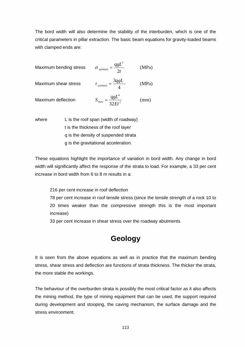
113
The bord width will also determine the stability of the interburden, which is one of the
critical parameters in pillar extraction. The basic beam equations for gravity-loaded beams
with clamped ends are:
Maximum bending stress (MPa)2
2
t
qgL(max)xy =σ
Maximum shear stress (MPa)4
3qgL(max)xy =τ
Maximum deflection (mm)32 2
4
Et
qgLSmax =
where L is the roof span (width of roadway)
t is the thickness of the roof layer
q is the density of suspended strata
g is the gravitational acceleration.
These equations highlight the importance of variation in bord width. Any change in bord
width will significantly affect the response of the strata to load. For example, a 33 per cent
increase in bord width from 6 to 8 m results in a:
216 per cent increase in roof deflection
78 per cent increase in roof tensile stress (since the tensile strength of a rock 10 to
20 times weaker than the compressive strength this is the most important
increase)
33 per cent increase in shear stress over the roadway abutments.
Geology
It is seen from the above equations as well as in practice that the maximum bending
stress, shear stress and deflection are functions of strata thickness. The thicker the strata,
the more stable the workings.
The behaviour of the overburden strata is possibly the most critical factor as it also affects
the mining method, the type of mining equipment that can be used, the support required
during development and stooping, the caving mechanism, the surface damage and the
stress environment.

114
The composition of the overburden strata is one of the critical factors affecting the
formation of a goaf during stooping and loading. Unlike the case in bord-and-pillar
sections, the load on the pillars in stooping sections changes constantly due to the
dynamic nature of the mining process. When competent massive sandstone, which does
not break during initial goafing, or a dolerite sill overlies the coal seam, the load on the
pillars will be higher than after failure of the sill or sandstone. This is due to the additional
load that has to be borne by the pillars in the vicinity of the goaf edge to support the
overburden spanning the goaf area.
Competent strata layers, such as thick dolerite sills and massive sandstone layers, can
result in the temporary arrest of caving at the base of these competent layers. Dolerite
sills in particular bridge over the goaf and deflect elastically. However, when the free span
at the base of the sill exceeds the critical span dimensions, it leads to the structural but
non-violent failure of the sill. This has been observed above various longwall panels in
South Africa.
When any form of total extraction is being contemplated, the effect on the surface must be
taken into account.
If a dolerite sill overlies the coal seams, two options are available:
• Designing the panels to be narrow enough to ensure that the dolerite sill does not
fail. This will cause the sill to bend without failing and will cause less surface
subsidence than when the sill fails.
• Designing the panels to be wide enough to ensure that the dolerite sill does fail.
This is desirable to avoid any excessive load on the pillars being extracted.
When the roof stratum is relatively weak and incompetent, the high compressive stresses
in the vicinity of the abutments are sufficient to cause shear failure of the strata. The
stress-induced fractures that develop in this stratum as a result of these stresses are near
vertical. As the lower roof stratum in a mined-out area is in tension, gravity will cause a
highly fractured roof stratum to cave readily. Because there are no competent roof layers,
caving of the roof is continuous and extends to surface.
Caving mechanism

115
The caving mechanism is also an important parameter in both single-seam and multi-
seam pillar extraction.
Two types of caving mechanism have been identified (Hill 1994). For small spans the
height of caving will be determined by the caving angle of the overlying strata. These
mechanisms are:
1. Bulking-factor-controlled caving (Figure 0–1 (a)) in which the height of caving will be
determined mainly by the bulking factor of the caved material. In this mechanism,
caving continues until the goaf material is in contact with the upper strata. As the pillar-
extraction line moves away, compaction of the goaf will take place. Bulking-factor-
controlled caving is typical of conditions where the strata consist of shales and
mudstones and are therefore relatively weak.
2. Parting-plane-controlled caving (Figure 0–1 (b))in which the caving height is
determined by the location of dominant parting planes within the roof strata. A waste
void will initially form between the caved waste and the overlaying strata. From the
extraction line into the goaf area, the strata will converge until they make contact with
the caved rock. Parting-plane-controlled caving is typical in conditions of alternating
layers of different strengths, where the layers are identified by well-defined parting
planes. Where thick sandstone layers are present, incompetent caving and therefore
voids can be expected, and as the pillar-extraction line advances, consolidation will
take place in the goaf.

116
a) bulking factor controlled caving
a) parting plane controlled caving
Figure 0–1 Two caving mechanisms as identified by Hill, 1994
Amount of scaling
As mentioned earlier, pillar strength is a function of pillar width. The strength of pillars
increases as the pillar width increases. However, the pillars deteriorate with time, and the
extent of this deterioration should be known in order to accurately calculate the strength of
pillars.
As the pillar width decreases, the bord width increases. The effect of bord width was
discussed above. As it increases, the stability of the workings decreases.
h
H
h
P
V

117
Effect of scaling and determination of amount of scaling is discussed in another
COALTECH project (Task 6.9.1). Therefore, the details of this work are not presented in
this report.
Geological discontinuities
Like most rock types, coal contains natural discontinuities, which have an effect on its
strength. In general, the greater the intensity of the discontinuities, the weaker the rock
mass becomes. The strength of coal pillars should therefore also be affected by the
density of the discontinuities in the coal.
These discontinuities are therefore important in designing layouts and support patterns.
The stability of the roof also decreases as the density of the discontinuities increases.
The direction of the discontinuities is as important as the density. Although in some cases
even major discontinuities may not be critical, in others minor slips become very important
due to their direction. Therefore, in order to accurately determine what mining layouts and
support patterns are likely to be unstable, all the geological discontinuities and their
directions should be known in advance.
1.29 Conclusions
Pillar extraction takes many forms and mines have adopted methods of removing
individual pillars to suit their particular needs. In ‘traditional’ stooping, it was recommended
practice to remove or destroy all snooks in order to allow the goaf to cave thereby
relieving the stress on the caving pillar line. Many of the pillar extraction methods now
used deliberately leave pre-designed snooks that prevent immediate caving but will crush
over time. Advantages of these methods are:
• the absence of a caving line, thus removing an area of high risk,
• immediate water table disturbances, and
• elimination of the problems/dangers associated with goaf ‘hang-ups’ and sudden
goaf collapses.
• Improved ventilation flows and methane drainage.

118
One major disadvantage of keeping up the goaf by the use of pre-designed snooks or by
the use of checker-board mining is the uncertainty of when the snooks or remaining pillars
are going to crush and allow the overburden strata to settle.
Contrary to previously held views, mines now do not believe that pillar extraction is a less
safe method than pillar development. This may be because pillar extraction is now done
by continuous miner, often by means of remote control, and also that the incorporation of
section employees in more risk assessment procedures has introduced a greater
awareness amongst the underground operators of the inherent dangers in pillar
extraction. Also, more use is now made of ‘partial’ pillar recovery and checker-board
systems where the formation of a goaf edge is prevented, thereby removing a hazardous
area from the system.
The cost of pillar extraction in comparison to pillar development is reported to be higher by
some mines but lower by others. Much depends on a mine’s costing procedures and
whether pillar extraction follows directly after pillar development or whether old panels
have to be rehabilitated.
Pillar extraction by means of shortwall equipment has been done successfully but a
particular problem can be the rate of retreat through the pillars. Over a face length of say
90 m made up of 4 fifteen metre square pillars and 5 six metre wide bords, coal is present
over only two thirds of the shortwall face length and the other third is ‘air’. Careful
consideration must be given to the logistics of utilising what is considered to be a highly
capital intensive method for the recovery of pillars.
The recovery of old pillars by underground pillar extraction has been shown to be feasible
in the number 4 Seam and the number 2 Seam in the Witbank Coalfield. Experience is
being gained which should be beneficial to the industry in the wider application of pillar
extraction to other parts of the Coalfield where suitable reserves may be found.

119
SECONDARY (PILLAR) EXTRACTION
SINGLE SEAMMULTI-SEAM
CALCULATEDESIGN SF
DepthMining heightPillar widthBord width
REQUIRED INFORMATIONDETAILED SURVEY OF THE PANELBOREHOLE LOGSACCESS TO WORKINGSDETAILED GEOTECHNICAL SURVEY (slips, joints, dykes etc.)SURFACE INFO (restrictions)
CALCULATECURRENT SF
Calculate amount of scallingDepthMining height (increased)Pillar width (decreased)Bord width (increased)
DETAILED INSPECTION OF
WORKINGS
Amount of scallingSurveyPanel widthPillar widthBord widthMining heightEffect of weatheringRoof conditionsCurrent bolt pattern
SURFACERESTRICTIONS
FULLPILLAR
EXTRACTION
CHECKERBOARD
EXTRACTIONLAYOUT
RE-CALCULATETHE SUPPORT
REQUIREMENTS(with the scalling)
CALCULATETHE ADD. SUPPORT
REQUIRED(IF REQUIRED)
CUTTINGDIRECTION
(panel & ind. pillar)
SNOOK SIZE
SUPPORT (finger/breaker line)
SURFACE DAMAGE(including sinkholes)
CRITICAL FACTORS
StrataRoof thicknessBord widthElastic modulus of
roof & boltTensile strengthWeathering effect
Adjacent panels (goaf)GeologyGeological discontinuitiesStress environment
Geological discontinuities
Numerical modellingPast experience
Performance of current supportSupport type
Immediate and overburdenstrata
CRITICAL FACTORSOverburden strataCompetent or incompetent strata thickness Depth of competent layer and workingsGeology thickness of roof & floor
Geology compt./incompt. layersPanel widthMining height
FINALVOLUMETRIC
RATIO
Pillar widthPanel widthMining heightBord widthSnook size
CALCULATEDESIGN SF
CALCULATECURRENT SF
DETAILED INSPECTION OF
WORKINGS
EXTRACTIONLAYOUT
RE-CALCULATETHE SUPPORT
REQUIREMENTS(with the scalling)
CALCULATETHE ADD. SUPPORT
REQUIRED(IF REQUIRED)
CUTTINGDIRECTION
(panel & ind. pillar)
SNOOK SIZE
SUPPORT (finger/breaker line)
SURFACE DAMAGE(including sinkholes)
FINALVOLUMETRIC
RATIO
SYSTEM EVALUATIONPRACTICAL
ECONOMICALLEGAL
YESIMPLEMENT
NO NO
HISTORYMULTI-SEAM MINING
IN ANY SEAM
DETAILED INSPECTION OF
WORKINGS
DETERMINE THECAVING MECHANISM
DETERMINE THECAVING MECHANISM
Immediate strataOverburden strata
ThicknessCaving angleBulking factor
IN BOTH SEAMSAmount of scallingSurveyPanel widthsPillar widthsBord widthsBarrier pillar widthsMining heightsEffect of weatheringRoof conditionsCurrent bolt patterns
CRITICAL FACTORS
GEOLOGICAL &GEOTECHNICAL INFO
GEOLOGICAL &GEOTECHNICAL INFO
Geological discontinuitiesImmediate roof characteristicsOverburden characteristicsCompt. & incompt. layers
GEOLOGICAL &GEOTECHNICAL INFO
GEOLOGICAL &GEOTECHNICAL INFO
Geological discontinuitiesImmediate roof characteristicsOverburden characteristicsCompt. & incompt. layers
DETAILED INSPECTION OF
WORKINGS
DETERMINE THEPARTING STABILITY
DETERMINE THECAVING MECHANISM
CAVING STILLCONTINUES
INITIAL NMTO INVESTIGATE THE
INTERACTION BETWEENTHE SEAMS(INTERACT)
NO
RECOMMENDEDWAIT LONGER
YES
NUMERICALMODELLING TO IDENTIFY THE
LAYOUT, CUTTINGDIRECTION, SNOOK
SIZE ANDMIN. DAMAGE
SURFACE DAMAGEALLOWED
YES
NO
FINALVOLUMETRIC
RATIO
NO
CONTINUES MONITORINGIS REQUIRED
Caving angleBulking factor
DETERMINEMINING
LAYOUT, CUTTINGDIRECTION, SNOOK SIZE
CHECK LAYOUTUSING NM FOR
POSSIBLE DAMAGE
SURFACE DAMAGEALLOWED
NO
FINALVOLUMETRIC
RATIO
CONTINUES MONITORINGIS REQUIRED
SYSTEM EVALUATIONPRACTICAL
ECONOMICALLEGAL
IMPLEMENT
Parting characteristics
CALCULATEDESIGN SF
DepthMining heightPillar widthBord width
CALCULATECURRENT SF
Calculate amount of scallingDepthMining height (increased)Pillar width (decreased)Bord width (increased)
RE-CALCULATETHE SUPPORT
REQUIREMENTS(with the scalling)
CALCULATEDESIGN SF
CALCULATECURRENT SF
RE-CALCULATETHE SUPPORT
REQUIREMENTS(with the scalling)
YESNO
StrataRoof thicknessBord widthElastic modulus of
roof & boltTensile strengthWeathering effect
SUPPORT (finger/breaker line)
YES
All the dimensionsas given above for
both seams
INTERACTS
SUPPORT (finger/breaker line)
YES NO
**PREFERRED METHODIS EXTRACTING FROM
TOP TO BOTTOM
DETERMINE PARTING
STABILITY
DETERMINE THECAVING MECHANISM
INITIAL NMTO INVESTIGATE THE
INTERACTION BETWEENTHE SEAMS(INTERACT)
NO
All the dimensionsas given above for
both seams
Geology compt./incompt. layersPanel widthMining height
YES
NO NO
Immediate and overburdenstrata
Pillar widthPanel widthMining heightBord widthSnook size
Figure 0–2 The critical factors in the design of pillar extraction

120
Effect of panel geometry in pillar extraction
1.30 Introduction
As mentioned earlier that the magnitude of the load acting on the pillars in the active mining zone
is a function of the panel geometry in pillar extraction. The magnitude of surface damage is also
a function of panel width. In order to investigate the effect of panel width in pillar extraction, this
study was conducted.
The effect of panel geometry on face-pillar stability and artificial barrier pillar stability was
investigated. The effect of backfilling on in-pillar and barrier pillar loading was also investigated.
LAMODEL, a boundary element program specially suited to coal modelling, was used to analyse
different layouts.
1.31 LAMODEL
LAMODEL is a boundary element code, which models tabular excavations as displacement
discontinuities (DD’s). These DD’s physically represent cracks, which is appropriate in the gold
and coal mining environment where seam height is typically less than one per cent of the
maximum dimension of the mining extent. The region of interest is discretised by regular gridding
with a fixed square element size. The geometry of the modelled region is rectangular. Solid and
void areas are specified on the DD plane to model pillars and excavations. A number of mining
steps may be simulated by changing elements from solid to void and vice versa when backfill is
modelled.
Seam stresses (in the solid) and convergence (in the excavated areas) are the primary outputs of
the program. In shallow excavations, the proximity of the surface may influence the stresses and
displacements within the seam. LAMODEL models this effect by placing a fictitious seam in
space such that a traction-free surface, representing ground level, is created.
LAMODEL is different from continuum boundary element codes in that the overburden is treated
as a stack of regularly spaced frictionless laminations. The formulation for this approach is based
on the theory of thin plates and it is assumed that the beds are always parallel and that no shear
stress or cohesion is present along the contacts. The size of the laminations is user-specified.
The effect of this assumption is to reduce the stiffness of the overburden such that convergence
is typically higher than for homogenous models. It is also possible to specify symmetry conditions
on any edge of the model in LAMODEL, so that infinitely repeating geometries can be modelled.

121
1.32 Model description
Five different layouts were used in the analysis. These layouts are presented in Figure 0–1 to
Figure 0–5.
These layouts are based on the changing pillar extraction options on pillar extraction stability to
include:
• three pillars mined leaving one row barrier (Model 1) (Figure 0–1),
• two pillars mined leaving one row barrier (Model 2) (Figure 0–2),
• three pillars mined leaving a two row barrier (Model 3) (Figure 0–3),
• two pillars mined leaving a two row barrier (Model 4) (Figure 0–4),
• common pillar extraction layout (all rows mined) (Model 5) (Figure 0–5),
• backfill models of first four models (Model 1, 2, 3 and 4) (Figure 0–1, Figure 0–2, Figure
0–3 and Figure 0–4)
The common pillar extraction practice of mining the total pillars in rows and columns, without
leaving any artificial barrier pillars in the centre of panel, was also modelled, Model 5. The results
from Model 1 to 4 were then compared with Model 5.
For each option, the change in mined shape from rectangular (one direction) to square to
rectangular (in the other direction) were modelled so as to determine progressive changes in
pillar, abutment and barrier stress distribution.
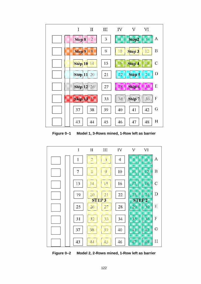
122
Figure 0–1 Model 1, 3-Rows mined, 1-Row left as barrier
Figure 0–2 Model 2, 2-Rows mined, 1-Row left as barrier
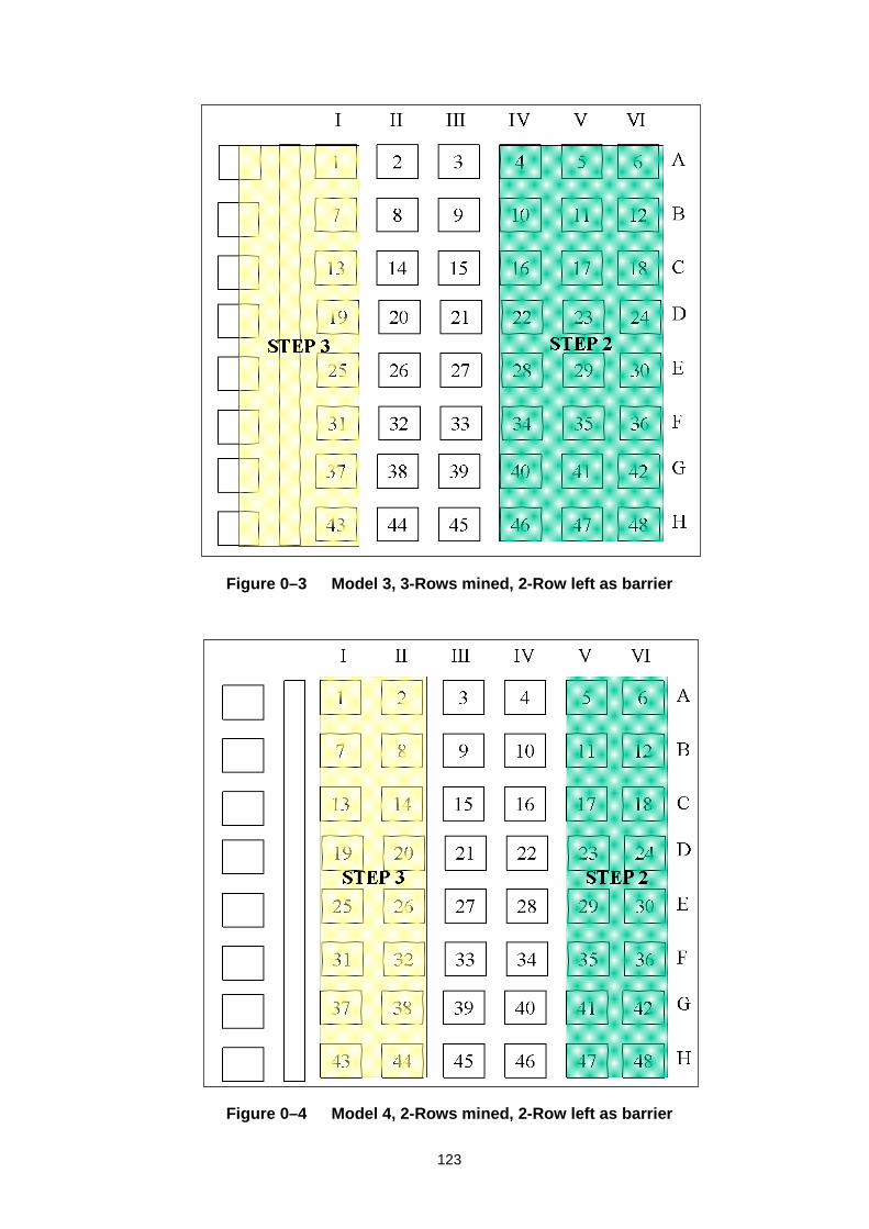
123
Figure 0–3 Model 3, 3-Rows mined, 2-Row left as barrier
Figure 0–4 Model 4, 2-Rows mined, 2-Row left as barrier

124
Figure 0–5 Model 5, All rows taken, common pillar extraction method
1.33 Material properties
The following material properties were used throughout the study:
Overburden Elastic Modulus (Ehost) = 30 GPa
Coal Elastic Modulus (Ecoal) = 4.0 GPa
Overburden density (γhost) = 0.027 MN/m3
Coal density (γcoal) = 0.016 MN/m3
Overburden Poisson’s Ratio (νhost) = 0.2
Coal Poisson’s Ratio (νcoal) = 0.3
Pillar width (wpillar) = 17.5 m
Mining height (h) = 4.5 m
Bord width (b) = 7.5 m
Depth below surface = 132 m
Backfill height (hbackfill) = 2.5 m
Backfill material properties are discussed in detail further in this report.

125
As it can be seen from the above material properties that the overburden material was assumed
to be significantly stiff.
1.34 Results
1.34.1 Effect of leaving centre pillars as barriers
As seen in this study that leaving one or two rows of pillars in the centre of the panel as artificial
barrier pillars has two major advantages. First of all, it will limit the panel width, which will
decrease the stress on the face pillar being extracted. Secondly, because it will limit the panel
width the amount of surface subsidence will be less compared to the full panel width extraction.
Although this second phenomenon cannot be modelled using numerical modelling tools, an
analytical model is being investigated as part of Task 2.4
In order to simulate the effect of artificial barrier pillars on stress in the face pillars, Model 1 was
constructed. The results are shown in Figure 0–6. The pillar stress is calculated on pillars, which
were one row behind the completed line of pillars being mined. For example, in Figure 0–6, in
mining step 1, the stress on pillar 39 was determined after mining the bords (primary production),
and in mining step 2, the stress on pillar 11 was determined (first row of 3-rows mined), in mining
step 3 the stress on pillar 17 was determined (second row of 3-rows mined), and all the results
were extracted using this process.
Figure 0–6 Effect of leaving artificial barrier pillars in the centre of the panel
Stresses on Corresponding Pillars(3-Rows taken - Model 1)
0
2
4
6
8
10
12
14
16
0 1 2 3 4 5 6 7
Mining Steps
Str
ess
(MP
a)

126
Figure 0–6 indicates that after mining step 3 the increase in stress acting on the face-pillars is
nearly constant. This highlights the importance of the change in mined shape from rectangular
(one direction) to square to rectangular (other direction).
This comparison was also done between Model 1 and 5 in order to determine the significance of
this phenomenon. The results are presented in Figure 0–7. This figure indicates that in Model 5,
which represent the common pillar extraction practice, the stress on the face-pillars does not
flatten out as it is the case in Model 1. Also, there are significantly higher stresses on the face-
pillars in Model 5 than Model 1. This is shown in Figure 0–8. This figure indicates that in mining
step 6 (the second last row of the right hand side of the panel) the stress on the face-pillars in
Model 5 is 45 per cent higher than Model 1 face-pillars.
From these results it is concluded that there is a great advantage of leaving artificial barrier pillars
in the centre of the panel with respect to stresses on the face-pillars.
Figure 0–7 Comparison between the Model 1 and 5 with respect to stress on face-pillars
Comparison of Taking All Rows & 3-Rows(Model 1 to Model 5)
0
5
10
15
20
25
0 1 2 3 4 5 6 7
Mining Steps
Str
ess
(MP
a)
Model 1
Model 5

127
Figure 0–8 The percentage difference between Model 1 and 5
1.34.2 The safety factor of the face-pillars
In the development of the safety factor concept (Salamon, 1967), the load acting on the pillars
was calculated using the Tributary Area Theory. The reason for that was in the development of
the strength formula, the maximum likelihood method was used with the failure load of the pillars
that failed calculated using the Tributary Area Theory. Therefore, the load acting on the pillars
extracted from the numerical modelling would not give the appropriate answer in determining the
safety factor of pillars. However, in order to demonstrate the constant safety factor of face pillars
after the square to rectangular transaction zone, Figure 0–9 was plotted. The blue line in this
figure represents the stress on the face-pillars (right-hand y-axis), and the red line represents the
safety factor of the face pillars (left-hand y-axis) calculated using the Salamon and Munro’s
strength formula with the load extracted from the numerical modelling.
Percentage Increase in Stress (All Rows & 3-Rows)(Model 1 to Model 5)
05
101520253035404550
0 1 2 3 4 5 6 7
Mining Steps
Per
cen
tag
e in
crea
se (
%)
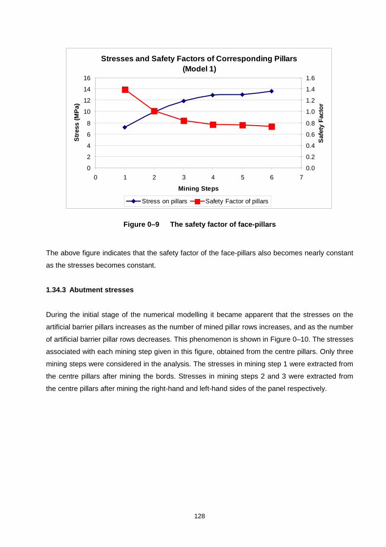
128
Figure 0–9 The safety factor of face-pillars
The above figure indicates that the safety factor of the face-pillars also becomes nearly constant
as the stresses becomes constant.
1.34.3 Abutment stresses
During the initial stage of the numerical modelling it became apparent that the stresses on the
artificial barrier pillars increases as the number of mined pillar rows increases, and as the number
of artificial barrier pillar rows decreases. This phenomenon is shown in Figure 0–10. The stresses
associated with each mining step given in this figure, obtained from the centre pillars. Only three
mining steps were considered in the analysis. The stresses in mining step 1 were extracted from
the centre pillars after mining the bords. Stresses in mining steps 2 and 3 were extracted from
the centre pillars after mining the right-hand and left-hand sides of the panel respectively.
Stresses and Safety Factors of Corresponding Pillars(Model 1)
0
2
4
6
8
10
12
14
16
0 1 2 3 4 5 6 7
Mining Steps
Str
ess
(MP
a)
0.0
0.2
0.4
0.6
0.8
1.0
1.2
1.4
1.6
Saf
ety
Fac
tor
Stress on pillars Safety Factor of pillars

129
Figure 0–10 The stresses acting on the artificial barrier pillars as the mining takes place
This figure indicates that as expected, Model 1 gave the maximum stress and Model 4 gave the
minimum artificial barrier pillar stress. The reason is that in Model 1, only one row of artificial
barrier pillar was left and three rows were mined on each side of the barrier pillars. In Model 4
only 2 rows of pillars were mined and two rows of barrier pillars were left.
Based on this figure it can be concluded that mining three rows of pillars on either side of the
artificial barrier pillars and leaving two rows of artificial barrier pillars is the most effective layout
for the panel (Model 3). This can be directly related to stability of the artificial barrier pillars and
the extraction ratios. While stress on the artificial barrier pillars is 50 per cent less in Model 3 than
in Model 1, the overall extraction gained by leaving one rows of pillars rather then two rows is
less than 20 per cent.
1.34.4 Effect of backfilling
As part of the study, the effect of the backfilling on stability of the artificial barrier pillars was also
investigated.
It is well known that the modelling of backfilling and backfill material has always been difficult for
various reasons.
Comparison of Abutment Stresses in Models 1, 2, 3 & 4
0
5
10
15
20
25
30
0 1 2 3 4
Mining Steps
Str
ess
(MP
a) Moldel 1
Model 2
Model 3
Model 4
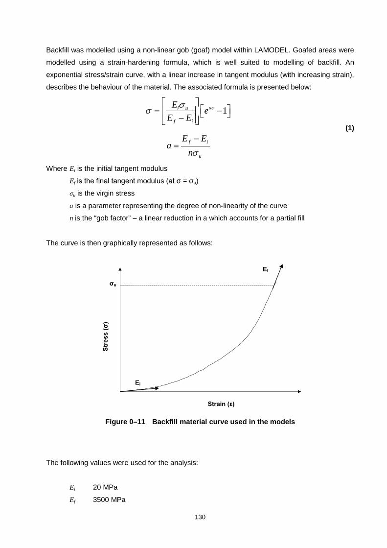
130
Backfill was modelled using a non-linear gob (goaf) model within LAMODEL. Goafed areas were
modelled using a strain-hardening formula, which is well suited to modelling of backfill. An
exponential stress/strain curve, with a linear increase in tangent modulus (with increasing strain),
describes the behaviour of the material. The associated formula is presented below:
1ai u
f i
f i
u
Ee
E E
E Ea
n
εσσ
σ
= − −
−=
(1)
Where Ei is the initial tangent modulus
Ef is the final tangent modulus (at σ = σu)
σu is the virgin stress
a is a parameter representing the degree of non-linearity of the curve
n is the “gob factor” – a linear reduction in a which accounts for a partial fill
The curve is then graphically represented as follows:
Strain (ε)
Stre
ss (σ
)
Ei
Ef
σu
Figure 0–11 Backfill material curve used in the models
The following values were used for the analysis:
Ei 20 MPa
Ef 3500 MPa

131
σu 3.564 MPa
n 1
In addition, the Poisson’s ratio is assigned a value of 0.1. These backfill properties are based on
a study conducted by J. Ryder on Sigma Colliery backfill project. However, the backfill curve
given in Figure 0–11 was upgraded so that the coal stiffness was approximated at 20 per cent
strain. This allows modelling of stiffer backfill. Also, this is believed to represent both weak-ashfill
at low strain and stiffer-cemented ashfill at high strains. Although these parameters represent a
generic backfill material, it is strongly recommended that backfill material properties should be
determined prior to underground application.
The results obtained from the backfilled and non-backfilled models are presented in the following
table. This table simply shows the percentage stress reduction due to backfilling on the artificial
barrier pillars. Note that “Left” and “Right” indicate the stress reductions after the left-hand and
right-hand side of the artificial barrier pillars mined (right-hand side of the barrier pillars mined
first).
Table 0–1 Percentage stress reductions on the artificial barrier pillars due to
backfilling
Left Right
Model 1 16.7 10.8
Model 2 13.9 6.9
Model 3 17.6 15.1
Model 4 8.6 7.6
This table indicates that total stress reduction varies from 8,6 to 17,6 per cent, depending on the
model, Model 3 shows the maximum reduction. From this result it should be highlighted that in
the artificial barrier pillar models, Model 3 (mining 3-rows, leaving 2-rows) gave the best
combination with respect to the abutment stress. Therefore, it can be concluded that, irrespective
of backfilling, Model 3 is the best combination for the section.
1.35 Conclusions
The following conclusions were extracted from the above results:

132
• Mining 3-rows of pillars in either side of the artificial barrier pillars and leaving 2-rows of
artificial barrier pillars is the most the effective layout for the given dimensions and panel
layout (Model 3). The belt can also be constructed between these two barrier pillars.
• Model 3 will also be more beneficial in terms of abutment stresses, should it have decided to
use backfilling.
This study is based on certain assumptions and certain parameters. Therefore, it is strongly
recommended that a detailed numerical modeling program, including nonlinear modeling, should
be conducted in order to obtain more accurate results with respect to stability of the artificial
barrier pillars and the overlying sandstone layer. This may result in different combinations and
layouts than being recommended.

133
Surcharge load in pillar extraction
1.36 Introduction
This section of the report details the calculation of the surcharge load in pillar extraction,
which is due to the overhang and abutment angle.
1.37 Calculation of surcharge load in pillar extraction
As mentioned earlier in the report that recommended safety factor of pillars is 1.8 for pillar
extraction. The reason for this is that the extra surcharge load caused by the overhang.
It is well known that the surcharge load has been distributed amongst the pillars at the
face. Mark (1997) suggested that the active mining zone (AMZ) is H5 , where H is depth
below surface.
Figure 0–1 Surcharge load due to overhang in pillar extraction
However, experiment conducted at Bosjesspruit Colliery as part of Task 2.13.1/2 showed
that the AMZ is H2.3 .
Bosjesspruit Colliery experiment and the numerical modeling results also indicated that
the surcharge load distribution of pillars is as follows:

134
Pillar number 1: carry 92.5 per cent of the surcharge load
Pillar number 2: carry 6.25 per cent of the surcharge load
Pillar number 1: carry 1.25 per cent of the surcharge load
The surcharge load acting on the pillar can be calculated as follows:
Weight of the wedge is:
HCgqH
Weight
=
2
tan* α
where H is depth below surface (m)
α is abutment angle (o)
C is centre distance (m)
g is density of overburden
q is gravitel acceleration
g is gravitational acceleration
The load applied by the wedge is:
2w
weightLS =
where w is pillar width (for rectangular pillars w1xw2)
The total load acting on the pillar is then:
ST LTATL +=
where TAT is Tributary Area Theory load and is:
2
2
025.0w
CHTAT =
Then, the safety factor of a pillar in the AMZ is
TLstrengthSF /=
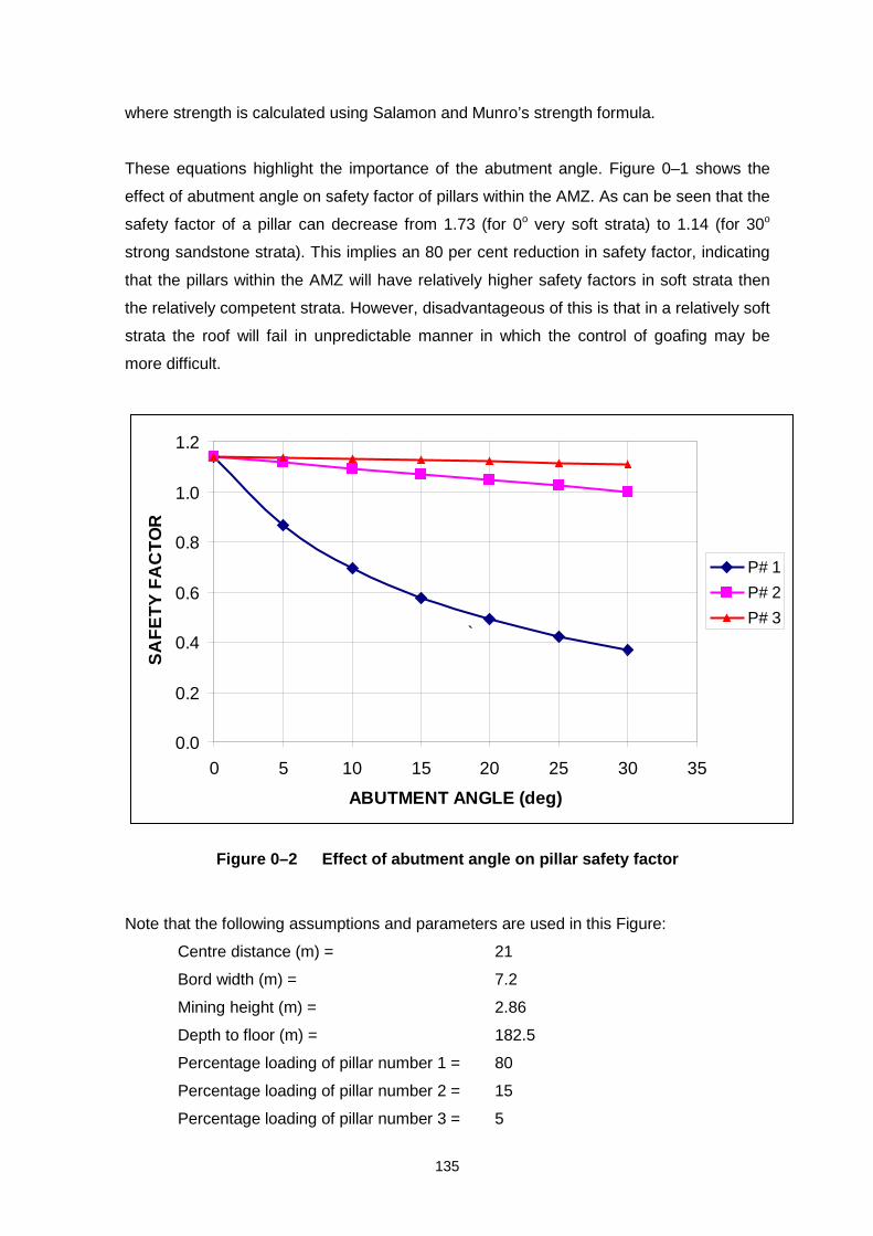
135
where strength is calculated using Salamon and Munro’s strength formula.
These equations highlight the importance of the abutment angle. Figure 0–1 shows the
effect of abutment angle on safety factor of pillars within the AMZ. As can be seen that the
safety factor of a pillar can decrease from 1.73 (for 0o very soft strata) to 1.14 (for 30o
strong sandstone strata). This implies an 80 per cent reduction in safety factor, indicating
that the pillars within the AMZ will have relatively higher safety factors in soft strata then
the relatively competent strata. However, disadvantageous of this is that in a relatively soft
strata the roof will fail in unpredictable manner in which the control of goafing may be
more difficult.
Figure 0–2 Effect of abutment angle on pillar safety factor
Note that the following assumptions and parameters are used in this Figure:
Centre distance (m) = 21
Bord width (m) = 7.2
Mining height (m) = 2.86
Depth to floor (m) = 182.5
Percentage loading of pillar number 1 = 80
Percentage loading of pillar number 2 = 15
Percentage loading of pillar number 3 = 5
0.0
0.2
0.4
0.6
0.8
1.0
1.2
0 5 10 15 20 25 30 35
ABUTMENT ANGLE (deg)
SA
FE
TY
FA
CT
OR
P# 1
P# 2
P# 3`
136
Mining method = CM
Density of overburden = 2500 kg/m3
As can be seen that the Bossjespruit Colliery experiment site dimensions were used in the
calculations in producing this Figure. This indicates that the safety factors of first line of
small pillars reduced from 1.14 to 0.37 (using Salamon and Munro formula), depending on
the abutment angle of the section. To date those pillars are still stable after 8 months. It
should also remember that this may well be due to high width to height ratio of pillars.
The importance of the abutment angle raises the question of measurement of it. The
abutment angle either can be measured underground, provided there is an access to goaf
edge, or it can be measured by monitoring the surface subsidence and plotting it against
the relative position of the face.
A spreadsheet program has been included together with all other programs to calculate
the surcharge load and safety factors within the AMZ in pillar extraction panels.

137
Mining risk decision methodology
It is proposed to rationalize the design process of pillar recovery into a two-stage process.
The first stage being a pre-feasibility stage in which a rapid assessment is made of all
panels being considered for mining, using risk evaluation procedures. The result of the
pre-feasibility is a risk ranking of the panels. The second stage of the design would be a
full feasibility study of those panels where pillar recovery is most likely to succeed. The
flow sheets have therefore been rationalized to fit into this proposed two staged scheme.
1.38 Flow sheets for risk decision methodology
A decision making process for pillar extraction should follow a flow sheet analysis. In
general, there are five important evaluations that must be considered. These are:
• Rock engineering evaluation
• Environmental risk evaluation
• Mining evaluation
• Coal beneficiation, and
• Financial evaluation
All these factors have their own constraints and limitations. It is therefore decided to
develop flow sheets for the above given evaluations.
• Flow sheet for rock engineering design: This sheet gives a detailed breakdown for
the steps that one would go through to carry out a rock engineering assessment
and design of single or multiple seam pillar recovery. The flow sheet for rock
engineering design is presented in Figure 0–1.
• Environmental flow sheet, which considers surface subsidence, groundwater
disturbance, coal fires and land alienation. The flow sheet for environment
evaluation is presented in Figure 0–2.

138
Figure 0–1 Flow sheet for rock engineering design
SECONDARY (PILLAR) EXTRACTION
SINGLE SEAMMULTI-SEAM
CALCULATEDESIGN SF
DepthMining heightPillar widthBord width
REQUIRED INFORMATIONDETAILED SURVEY OF THE PANELBOREHOLE LOGSACCESS TO WORKINGSDETAILED GEOTECHNICAL SURVEY (slips, joints, dykes etc.)SURFACE INFO (restrictions)
CALCULATECURRENT SF
Calculate amount of scallingDepthMining height (increased)Pillar width (decreased)Bord width (increased)
DETAILED INSPECTION OF
WORKINGS
Amount of scallingSurveyPanel widthPillar widthBord widthMining heightEffect of weatheringRoof conditionsCurrent bolt pattern
SURFACERESTRICTIONS
FULLPILLAR
EXTRACTION
CHECKERBOARD
EXTRACTIONLAYOUT
RE-CALCULATETHE SUPPORT
REQUIREMENTS(with the scalling)
CALCULATETHE ADD. SUPPORT
REQUIRED(IF REQUIRED)
CUTTINGDIRECTION
(panel & ind. pillar)
SNOOK SIZE
SUPPORT (finger/breaker line)
SURFACE DAMAGE(including sinkholes)
CRITICAL FACTORS
StrataRoof thicknessBord widthElastic modulus of
roof & boltTensile strengthWeathering effect
Adjacent panels (goaf)GeologyGeological discontinuitiesStress environment
Geological discontinuities
Numerical modellingPast experience
Performance of current supportSupport type
Immediate and overburdenstrata
CRITICAL FACTORSOverburden strataCompetent or incompetent strata thickness Depth of competent layer and workingsGeology thickness of roof & floor
Geology compt./incompt. layersPanel widthMining height
FINALVOLUMETRIC
RATIO
Pillar widthPanel widthMining heightBord widthSnook size
CALCULATEDESIGN SF
CALCULATECURRENT SF
DETAILED INSPECTION OF
WORKINGS
EXTRACTIONLAYOUT
RE-CALCULATETHE SUPPORT
REQUIREMENTS(with the scalling)
CALCULATETHE ADD. SUPPORT
REQUIRED(IF REQUIRED)
CUTTINGDIRECTION
(panel & ind. pillar)
SNOOK SIZE
SUPPORT (finger/breaker line)
SURFACE DAMAGE(including sinkholes)
FINALVOLUMETRIC
RATIO
SYSTEM EVALUATIONPRACTICAL
ECONOMICALLEGAL
YESIMPLEMENT
NO NO
HISTORYMULTI-SEAM MINING
IN ANY SEAM
DETAILED INSPECTION OF
WORKINGS
DETERMINE THECAVING MECHANISM
DETERMINE THECAVING MECHANISM
Immediate strataOverburden strata
ThicknessCaving angleBulking factor
IN BOTH SEAMSAmount of scallingSurveyPanel widthsPillar widthsBord widthsBarrier pillar widthsMining heightsEffect of weatheringRoof conditionsCurrent bolt patterns
CRITICAL FACTORS
GEOLOGICAL &GEOTECHNICAL INFO
GEOLOGICAL &GEOTECHNICAL INFO
Geological discontinuitiesImmediate roof characteristicsOverburden characteristicsCompt. & incompt. layers
GEOLOGICAL &GEOTECHNICAL INFO
GEOLOGICAL &GEOTECHNICAL INFO
Geological discontinuitiesImmediate roof characteristicsOverburden characteristicsCompt. & incompt. layers
DETAILED INSPECTION OF
WORKINGS
DETERMINE THEPARTING STABILITY
DETERMINE THECAVING MECHANISM
CAVING STILLCONTINUES
INITIAL NMTO INVESTIGATE THE
INTERACTION BETWEENTHE SEAMS(INTERACT)
NO
RECOMMENDEDWAIT LONGER
YES
NUMERICALMODELLING TO IDENTIFY THE
LAYOUT, CUTTINGDIRECTION, SNOOK
SIZE ANDMIN. DAMAGE
SURFACE DAMAGEALLOWED
YES
NO
FINALVOLUMETRIC
RATIO
NO
CONTINUES MONITORINGIS REQUIRED
Caving angleBulking factor
DETERMINEMINING
LAYOUT, CUTTINGDIRECTION, SNOOK SIZE
CHECK LAYOUTUSING NM FOR
POSSIBLE DAMAGE
SURFACE DAMAGEALLOWED
NO
FINALVOLUMETRIC
RATIO
CONTINUES MONITORINGIS REQUIRED
SYSTEM EVALUATIONPRACTICAL
ECONOMICALLEGAL
IMPLEMENT
Parting characteristics
CALCULATEDESIGN SF
DepthMining heightPillar widthBord width
CALCULATECURRENT SF
Calculate amount of scallingDepthMining height (increased)Pillar width (decreased)Bord width (increased)
RE-CALCULATETHE SUPPORT
REQUIREMENTS(with the scalling)
CALCULATEDESIGN SF
CALCULATECURRENT SF
RE-CALCULATETHE SUPPORT
REQUIREMENTS(with the scalling)
YESNO
StrataRoof thicknessBord widthElastic modulus of
roof & boltTensile strengthWeathering effect
SUPPORT (finger/breaker line)
YES
All the dimensionsas given above for
both seams
INTERACTS
SUPPORT (finger/breaker line)
YES NO
**PREFERRED METHODIS EXTRACTING FROM
TOP TO BOTTOM
DETERMINE PARTING
STABILITY
DETERMINE THECAVING MECHANISM
INITIAL NMTO INVESTIGATE THE
INTERACTION BETWEENTHE SEAMS(INTERACT)
NO
All the dimensionsas given above for
both seams
Geology compt./incompt. layersPanel widthMining height
YES
NO NO
Immediate and overburdenstrata
Pillar widthPanel widthMining heightBord widthSnook size
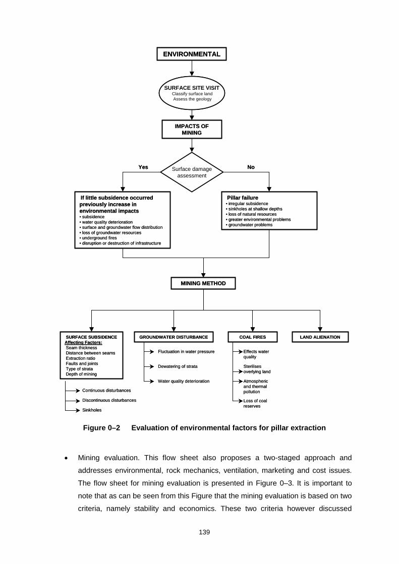
139
Figure 0–2 Evaluation of environmental factors for pillar extraction
• Mining evaluation. This flow sheet also proposes a two-staged approach and
addresses environmental, rock mechanics, ventilation, marketing and cost issues.
The flow sheet for mining evaluation is presented in Figure 0–3. It is important to
note that as can be seen from this Figure that the mining evaluation is based on two
criteria, namely stability and economics. These two criteria however discussed
SURFACE SITE VISITClassify surface landAssess the geology
ENVIRONMENTAL
IMPACTS OF MINING
Surface damageassessment
Yes No
If little subsidence occurred previously increase in environmental impacts• subsidence• water quality deterioration• surface and groundwater flow distribution• loss of groundwater resources• underground fires• disruption or destruction of infrastructure
Pillar failure• irregular subsidence• sinkholes at shallow depths• loss of natural resources• greater environmental problems• groundwater problems
MINING METHOD
SURFACE SUBSIDENCEAffecting Factors:Seam thicknessDistance between seamsExtraction ratioFaults and jointsType of strataDepth of mining
GROUNDWATER DISTURBANCE COAL FIRES LAND ALIENATION
Fluctuation in water pressure
Dewatering of strata
Water quality deterioration
Continuous disturbances
Discontinuous disturbances
Sinkholes
Effects water quality
Sterilisesoverlying land
Atmospheric and thermal pollution
Loss of coal reserves

140
separately. This indicates that if the logistics are appropriate for pillar extraction,
which is a function of economics, and the area is safe to extract the pillars, the
mining evaluation will indicate “implementation”.
Figure 0–3 Evaluation of mining factors for pillar extraction
CONDITIONS OF THE PANEL
PRE-RISK ASSESSMENTEvaluation of old pillarsclean up Yes� No�ventilation risk Yes� No�fire risk Yes� No�explosion risk Yes� No�age factor Yes� No�safety problems Yes� No�dust Yes� No�dewatering Yes� No�access to workings Yes� No�re-supporting Yes� No�re-infrastructure Yes� No�
Roof conditionsstability Yes� No�pillar load Yes� No�
Environmental conditionssurface subsid. Yes� No�groundwater Yes� No�pollution Yes� No�
Coal qualitymarket needs Yes� No�gain > cost Yes� No�
Open up No
Yes
ASSESSMENT OF PREVAILINGMINING CONDITIONS Pillars are stable?
RISK CRITERIA12345
ECONOMICALSAFE
Yes
IMPLEMENTATION
No
PRE-FEASIBILITY STUDY
No
Stop
Yes
ECONOMIC ANALYSIS
Yes
StopNo
DETAILED COST ANALYSIS
NoStop

141
• Beneficiation flow sheet considers coal quality and marketing issues and addresses
the coal processing plant and associated costs. The flow sheet for beneficiation
evaluation is presented in Figure 0–4.
Figure 0–4 Evaluation of coal beneficiation for pillar extraction
COAL BENEFICIATION
Requirenew plant?
LABORATORY TESTING
Yes
CAPITAL ESTIMATE
TYPES OF PRODUCTS
OPERATIONAL COSTS
LabourElectric powerMaterials and spare partsTailings treatmentDiscard handlingMaintenance
COAL PROCESSING PLANT DESIGN
Marketneeds?
No
Yes
No
ADDITIONALOPERATIING COSTSLabourElectric powerMaterials and spare partsTailings treatmentDiscard handlingMaintenance
Stop
No
PRODUCTION
Yes
Cost of beneficiati
on
DETAILED COST ANALYSIS

142
• Cost of opening up flow sheet. This flow sheet considers costs associated with
obtaining access to the panel. The flow sheet for financial or cost evaluation is
presented in Figure 0–5.

143
Figure 0–5 Financial evaluation for pillar extraction
ECONOMIC ANALYSIS OF OPENING UP
PANEL
No
Yes Capitalrequired
EconomicNo
Yes
No
Stop
YesCapital
required
Operational costs
Economic Stop
Yes
Yes
No
Yes
No
Operational costs
No
No
YesAvailable
pumps
Yes Operational costs
Capital costs
No
EconomicNo
Stop
No
Yes
Capitalrequired
Yes
Operational costs
EconomicNo
Stop
Yes
IMPLEMENT
ventilation
Re-supporting
Dewatering
Clean up

144
Most of the above flow sheets propose data collection, some form of pre-feasibility
assessment followed by a more detailed assessment. Costs are an element of all of the
flow sheets. From the flow sheets, it is clear that any consideration of pillar recovery
mainly involves the stability considerations
These flow sheets also indicate that there is considerable overlap between the different
flow sheets. In addition, the connection between the different flow sheets is not clear in
terms of an overall investigation. It was therefore decided to developed rationalised flow
sheets. The first objective of the rationalisation process was therefore to design an overall
flow sheet for the decision process.
1.39 Overall flow sheet for decision process
The overall flow sheet for the decision process to proceed with pillar recovery is presented
in Figure 0–9. This flow sheet shows the two stage process, once a decision has been
take to consider pillar recovery, a pre-feasibility study is done which ranks the risk of pillar
recovery in the panels. This is a rapid risk assessment technique and relies on data
currently available. The pre-feasibility study will classify the panels in low, moderate and
high risk categories or no-go because of a “fatal flaw”.
All panels with a low to moderate risk will be considered in a full feasibility study, which is
the full economical analysis of the panel. If a panel fails the feasibility study, it should be
placed in a holding area for consideration at a later stage, when market or other
conditions may have changed, allowing the panel to be recovered. Panels having a high
risk rating from the pre-feasibility study should also be re-considered after 3 years.
Figure 0–9 also shows that the decision to recover pillars in a panel is taken in two stages.
The first decision, to discard a panel, is taken as part of the pre-feasibility, when a panel
may be discarded because of a fatal flaw. Fatal flow can be any obvious reason, such as
pillar extraction under the Sasol factories. The second decision, whether to proceed or
not, is only taken after the feasibility study, and is taken on the basis of the panel being
economically viable to mine. A third outcome is possible, where a panel is placed on a
holding list, to be re-considered if conditions change. This limitation of the decision
process to only two junctions differs from the above given flow sheets in which numerous
decision junctions were proposed.

145
This final flow sheet becomes a pillar recovery management system. It prioritises panels
for recovery, eliminates panels that cannot be recovered and ensures that panels that are
marginal are reviewed at a later date. It also simplifies the decision process to two
opportunities only.
1.40 Detail of pre-feasibility risk assessment
The development of a risk rating system for pre-feasibility study for pillar extraction is
presented below. This system has been incorporated into a spreadsheet assisted
decision-making tool.
1.40.1 Objectives in developing risk assessment procedure
A pre-feasibility risk assessment should first aim at eliminating panels that cannot be
extracted owing to factors that preclude extraction, called “fatal flaws”. The risk associated
with extracting the remaining panels should then be determined so that the panels may be
ranked according to their suitability for pillar recovery. The risk evaluation system should
be simple to calculate and should include all the relevant factors.
1.40.2 Causes of instability
The main causes of instability, that may prevent pillar recovery, were categorized as
follows:
• local instability
• regional instability
• multi-seam instability
Each of these main causes was further decomposed into the underlying causes. A total of
38 causing factors were identified, as shown in Figure 0–6. These causes are considered
to be root causes for the purpose of the risk rating system. If necessary, they can be
broken down further into their constituent components.
The probability of each root cause resulting in the top fault has to be evaluated. A
qualitative probability assignment system was used, where the probability is assigned
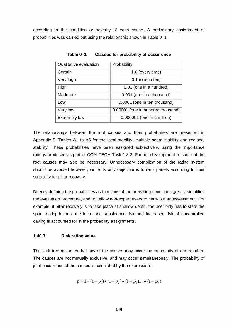
146
according to the condition or severity of each cause. A preliminary assignment of
probabilities was carried out using the relationship shown in Table 0–1.
Table 0–1 Classes for probability of occurrence
Qualitative evaluation Probability
Certain 1.0 (every time)
Very high 0.1 (one in ten)
High 0.01 (one in a hundred)
Moderate 0.001 (one in a thousand)
Low 0.0001 (one in ten thousand)
Very low 0.00001 (one in hundred thousand)
Extremely low 0.000001 (one in a million)
The relationships between the root causes and their probabilities are presented in
Appendix 5, Tables A1 to A5 for the local stability, multiple seam stability and regional
stability. These probabilities have been assigned subjectively, using the importance
ratings produced as part of COALTECH Task 1.8.2. Further development of some of the
root causes may also be necessary. Unnecessary complication of the rating system
should be avoided however, since its only objective is to rank panels according to their
suitability for pillar recovery.
Directly defining the probabilities as functions of the prevailing conditions greatly simplifies
the evaluation procedure, and will allow non-expert users to carry out an assessment. For
example, if pillar recovery is to take place at shallow depth, the user only has to state the
span to depth ratio, the increased subsidence risk and increased risk of uncontrolled
caving is accounted for in the probability assignments.
1.40.3 Risk rating value
The fault tree assumes that any of the causes may occur independently of one another.
The causes are not mutually exclusive, and may occur simultaneously. The probability of
joint occurrence of the causes is calculated by the expression:
)1()....1()1()1(1 321 nppppp −•−•−•−−=

147
Figure 0–6 Fault tree for stability risk evaluation
Regional instability Local
instability Multi-seam instability
Stress hazards
Probability that pillar recovery cannot be done
Subsidence hazards
Strata caving hazards
Pillars are unstable
Roof is unstable
Floor instabiltiy
Other seam not stooped
Cannot mine over old workings
Cannot mine under old workings
Other seam stooped
Regional geology hazards
Field stresses Adjacent mining
Dolerite sills Sandstone beams Depth/span ratio
Surface usage Subsidence mode Hydrology
Factor of safety Pillar age Pillar scaling Pillar jointing
Age of workings Roof collapse Jointing in roof Roof composition
Floor composition Floor undulations Presence of water Age of workings
Major lineaments Faults Intrusions
Parting composition Parting thickness Parting jointing
Parting instability
Other seam pillar instability
Other workings age Other seam FOS Superposition Barriers Remnants
Seam separation Goaf consolidation Remnant pillars
Seam separation Goaf consolidation Remnant pillars Groundwater
or
or
or
or
or
or

148
where pi is the probability of occurrence of cause i. Once the probability of the top fault
has been determined, a risk rating is calculated. Since the objective is to arrive at a risk
rating on a scale of 1 to 100, the following expression was used to convert the
probabilities to a rating number:
1006
)log(6•
+
=p
R
The resulting relationship between the probability (p) and risk rating (R) is presented in
Table 0–2.
Table 0–2 Relationship between probability of unsuccessful pillar recovery and
risk rating values
Probability (p) Risk category Risk rating (R)
1.0 (every time) Cannot be done 100
0.1 (one in ten) Very risky 83
0.01 (one in a hundred) Risky 67
0.001 (one in a thousand) Some risk 50
0.0001 (one in ten thousand) Low risk 33
0.00001 (one in hundred thousand) Very low risk 17
0.000001 (one in a million) Extremely low risk 0
Each category of risk represents an order of magnitude change in the probability of
unsuccessful pillar recovery. The manner in which the risk rating is calculated, results in
approximately a doubling of the probability of failure for every five point increase in the
rating.
1.40.4 Development of spreadsheet
In order to test the approach described above, a spreadsheet program was developed
which models the fault tree shown in Figure 0–6 and contains the relationships between
the causes and assigned probabilities shown in Appendix 5, Tables A1 to A5. To facilitate
the rating procedure, a number of data entry forms were created in the spreadsheet,
which allow the user to rapidly enter the assessed conditions and calculate the
probabilities. The spreadsheet was developed mainly to test the approach proposed here,

149
but may quite easily be developed for general use. The spreadsheet allows users to
modify the assigned probabilities and add new causes, if required.
1.40.5 Typical results
The spreadsheet program was used to test a number of hypothetical cases of pillar
recovery. The details of two cases are presented here. The first was a panel in a single
seam situation and the second a panel in a multi-seam situation. All the basic parameters
were the same for the two panels, and may be summarized as follows:
Pillar extraction assumed to occur in a 2.5 m high seam at a depth of 120 m. The panel
width was 180 m and the factor of safety of the pillars was between 1.3 and 1.6. The
pillars were 20 years old. Geological conditions were assumed to be favourable.
In the case of the multiple seam extraction scenario, it was assumed that the pillars in the
second seam were in a similar condition as those in the first seam, and the parting was
shale with a thickness of 8m, which is larger than the 6m bord width.
The results of the risk rating system are presented in Appendix 5, Tables A6 and A7 for
the single seam and multiple seam cases respectively. The results show that the
probability that pillar recovery cannot be done is 0.39 per cent for the multi-seam case,
corresponding to a risk rating of 60 and 0.27 per cent for the single seam case, with a risk
rating of 57. Both endeavours fall into a risk category of “risky”. The risk of failure is about
44 per cent higher for the multi-seam case compared to the single seam case.
Figure 0–7 and Figure 0–8 show the total and component risks for the two cases in
histogram form. The histograms show clearly which components are responsible for the
majority of the risk.
A number of test cases were carried out to determine the range of probabilities and risk
categories that may be achieved using this system and whether the resulting risk
categories were reasonable. The test cases were selected to represent a range of
conditions, from a very unfavourable multi-seam situation to an ideal single Seam
scenario. The results are summarized briefly in Table 0–3. The results show that the risk
rating is expected to lie between values of between about 50 and 90 for typical pillar
extraction scenarios. The risk categories vary between “very risky” and “low risk”. These
categories appear to describe the risk appropriately.

150
Table 0–3 Categories for typical pillar extraction scenarios
Brief description
Probability that pillar recovery cannot be done
Risk rating Risk category
Extraction of >20 year old pillars with low factors of safety in poor condition in multi-seam scenario with thin, weak shale parting under dolerite sill
22% 89 Very risky
Extraction of 15 year old pillars with low factors of safety in favourable geological conditions in multiple Seam conditions.
4.6% 78 Risky
Extraction of 15 year old pillars in single Seam conditions with favourable geological conditions
3.4% 76 Risky
Extraction of 5 year old pillars in single Seam conditions with moderately poor geological conditions
0.54% 62 Some risk
Extraction of 1 year old pillars under ideal conditions 0.09% 49 Low risk
0.00%
0.01%
0.10%
1.00%
10.00%
100.00%
PILL
AR IN
STAB
ILIT
YRO
OF
INST
ABIL
ITY
FLOO
R IN
STAB
ILIT
YM
ULTI
-SEA
M IN
STAB
ILITY
CAVI
NG H
AZAR
DSU
BSID
ENCE
HAZ
ARD
REGI
ONAL
GEO
LOGY
HAZ
ARD
STRE
SS H
AZAR
D
Prob
abilit
y
Total probability of failure Components
Very risky
Low risk
Some risk
Risky
Very low risk
Figure 0–7 Probability histogram –extraction of 20 year old pillars in a single
Seam setting

151
0.00%
0.01%
0.10%
1.00%
10.00%
100.00%
PILL
AR IN
STAB
ILIT
YR
OO
F IN
STAB
ILIT
YFL
OO
R IN
STAB
ILIT
YM
ULT
I-SEA
M IN
STAB
ILIT
YC
AVIN
G H
AZAR
DSU
BSID
ENC
E H
AZAR
DR
EGIO
NAL
GEO
LOG
Y H
AZAR
DST
RES
S H
AZAR
D
Prob
abili
ty
Total probability of failure Components
Very risky
Low risk
Some risk
Risky
Very low risk
Figure 0–8 Probability histogram –extraction of 20 year old pillars in multi-Seam
conditions
1.40.6 Requirement further input and refinement
The development of this risk rating system has been based on a combination of
judgement of project staff and the list of factors in the report of Task 1.8.2.
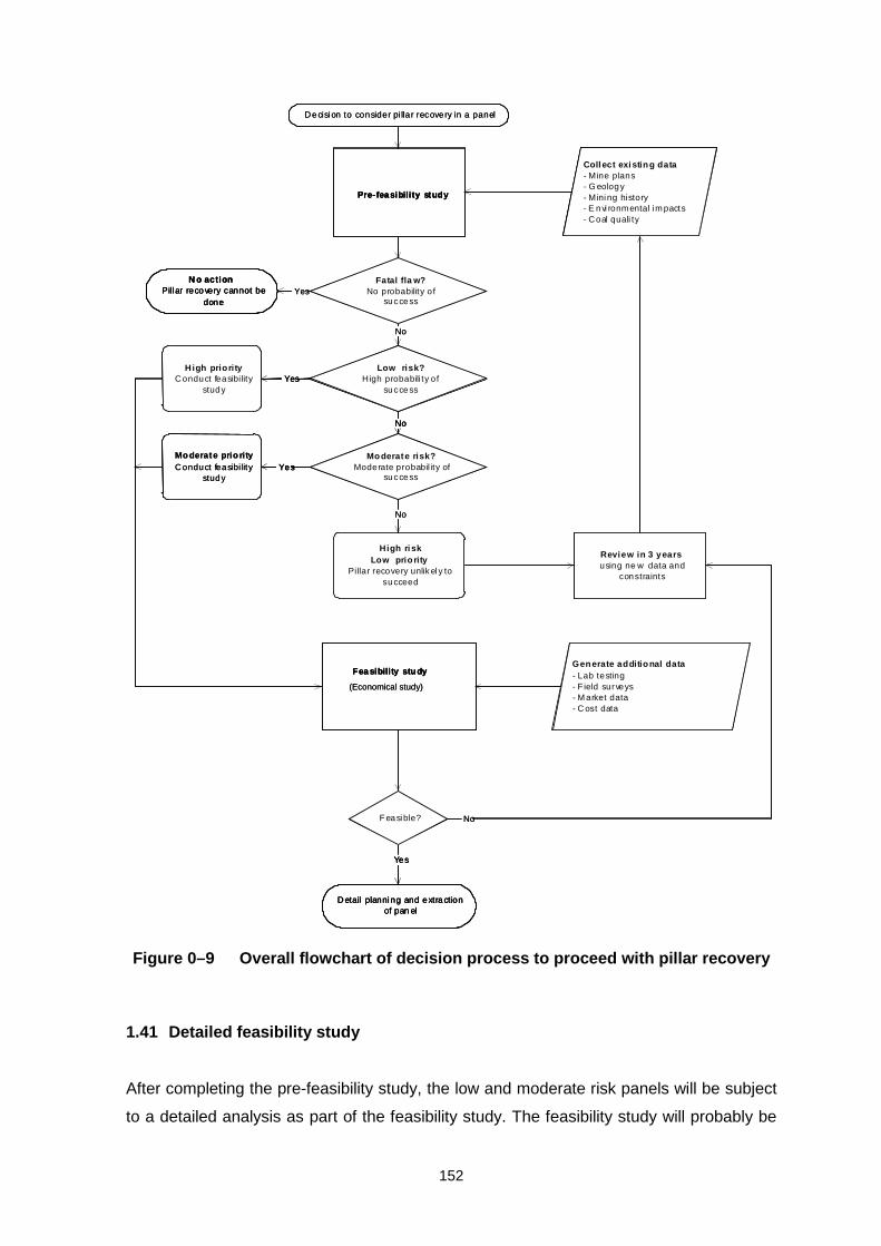
152
High riskLow prio rity
Pillar recovery unlik el y tosucceed
N o actionPill ar recovery cannot be
done
F easible?
Low risk?High probabili ty of
success
No
Yes
YesMo derate prio rityConduct feasibi lity
study
Detail planning and extractionof pan el
High priorityConduct feasibi lity
study
Yes
Collect existin g data- Mine plans- G eology- Mining history- E nvi ronmental im pacts- Coal quali ty
Pre-feasibility study
Gen erate additio nal data- Lab testing- F ield surveys- M arket data- C ost data
Moderate risk?Moderate probabil ity of
success
Fea sibility stu dy
Review in 3 yearsusing ne w data and
constraints
No
Decisi on to consider pi llar recovery in a panel
No
Yes
No
Fatal fla w?No probability of
success
(Economical study)
High riskLow prio rity
Pillar recovery unlik el y tosucceed
N o actionPill ar recovery cannot be
done
F easible?
Low risk?High probabili ty of
success
No
Yes
Yes
High riskLow prio rity
Pillar recovery unlik el y tosucceed
N o actionPill ar recovery cannot be
done
F easible?
Low risk?High probabili ty of
success
No
Yes
YesMo derate prio rityConduct feasibi lity
study
Detail planning and extractionof pan el
High priorityConduct feasibi lity
study
Yes
Collect existin g data- Mine plans- G eology- Mining histo
Moderate prio rityConduct feasibi lity
study
Detail planning and extractionof pan el
High priorityConduct feasibi lity
study
Yes
Collect existin g data- Mine plans- G eology- Mining history- E nvi ronmental im pacts- Coal quali ty
Pre-feasibility studyPre-feasibility study
Gen erate additio nal data- Lab testing- F ield surveys- M arket data- C ost data
Moderate risk?Moderate probabil ity of
success
Fea sibility stu dyFea sibility stu dy
Review in 3 yearsusing ne w data and
constraints
No
Decisi on to consider pi llar recovery in a panel
No
Yes
No
Fatal fla w?No probability of
success
(Economical study)
Figure 0–9 Overall flowchart of decision process to proceed with pillar recovery
1.41 Detailed feasibility study
After completing the pre-feasibility study, the low and moderate risk panels will be subject
to a detailed analysis as part of the feasibility study. The feasibility study will probably be

153
carried out for a number of panels at a time. The main objective of the feasibility study is
to consider all constraints to extracting a panel and producing operational and capital
costs so that the economic viability of pillar extraction can be assessed.
The flowchart for the feasibility study is presented in Figure 0–10. The first stage of the
feasibility study would be to determine the constraints to pillar recovery in a panel. All the
disciplines would contribute to defining what can and cannot be done. Interaction between
the disciplines will be necessary, since findings of one discipline will affect other
disciplines. Mining and environmental regulations and safety considerations form an
important part of the constraints. Figure 0–10 presents the main considerations for each
discipline, based on the flow sheets given above. The definition of constraints provides a
clear set of specifications that will allow a mining engineer to select an appropriate mining
method.
Once the mining method has been selected, it will be possible to calculate the mineable
reserve. All the constraints provided by the different disciplines should be considered. The
reserve tonnage is required for the economic evaluation and mine design stage.
During the design and costing stage, each discipline is required to carry out designs to a
sufficient level of accuracy to allow capital and operating costs to be estimated. The main
considerations are listed in Figure 0–10. The final part of the feasibility study is a financial
evaluation. The results of the financial evaluation are used to decide whether to proceed
with pillar recovery or not, as shown in Figure 0–10.

154
Start
Continue
Select mining method
Design and costing
Financial evaluation- royalties and taxes- cash flow- sensitivity- NPV, IRR, Cost benefit ratio
Determine constraints
M ining Constraints- panel conditions- dilution- mining equipment- access- ventilation- infrastructure- safety- regulations
Rock Eng Constraints- subsidence- pillar stability- roof stabil ity- extraction ratio- barriers- seam interaction- safety- regulations
Environmental Constraints- subsidence effects- water quality- groundwater flow- underground fires- land alienation- safety- regulations
Beneficiation Constraints- plant l imitations- coal quality- market requirements- plant capabilities- discard handling- safety- regulations
Mining design- access and opening up - extraction method - production rate- equipment lis t- consumables list- staffing- ventilation- infrastructure- cost of opening up- capital cost estimate- mining cost estimate
Rock Eng. design- p illar design- b arrier pil lar design- subsidence assessment- support design- extraction sequence- support sequence- equipment costing- support costing
Environmental design- subsidence effects- subsidence rehabilitation- hydrological analysis- groundwater rehabilitation- coal fire assessment- monitoring systems- capital costs- operating costs
Beneficiation design- plant evaluation- discard handing- tail ings treatment- staffing- infrastructure- maintenance- plant design- operating costs- capital costs
Calculate mineable reserve
Figure 0–10 Flowchart for feasibility study

155
Mining method decision methodology
1.42 Introduction
The objective of this report is to present a methodology for selecting the best method of
pillar recovery for a particular panel that has been mined by bord and pillar methods in the
past. The following methods of coal pillar recovery are under consideration in this report:
• Full pillar recovery in which all the pillars are recovered using typical pillar extraction
methods;
• Checker-board pillar recovery: in which every second pillar is recovered;
• Pillar splitting: every pillar is split into two smaller pillars by driving a roadway through
the pillar;
• Pillar quartering: every pillar is split into four smaller pillars by driving two roadways at
right angles through the pillar.
In order to select the best method, the differences between the methods were first listed,
under the topics of rock engineering, mining, environmental and beneficiation. Similarities
between the methods were ignored, since they would apply equally to all the methods,
and would not play a role in selecting a particular method above another.
Once the differences were identified, the requirements for success of the methods were
listed, based on the differences. These lists formed the basis for drawing up a checklist
that may be used to assess the applicability of each mining method to a particular panel.
This process allows unsuitable methods to be eliminated. If more than one mining method
survives the checking process, a decision support system may be used to select the best
method. The decision support system is based on the Analytical Hierarchy Process
developed by Saaty (1994). A spreadsheet has been developed which uses the list of
differences between the methods to evaluate their suitability for a given situation.
1.43 Differences between four selected mining methods
The following tables lists the four selected mining methods and the differences between
them, in terms of rock engineering, mining, environmental and beneficiation
characteristics. The following abbreviations were used: Full pillar extraction (FP), checker-

156
board extraction (CB), pillar splitting (PS) and pillar quartering (PQ). The differences
between the methods are used to develop the method selection process.

157
Table 0–1 Differences between four selected mining methods
Mining method
Rock
Engineering FP CB PS PQ
Pillar safety factor
Adequate safety factor required to accommodate high abutment loading
Abutment loading not as severe as for FP
Abutment loading not as severe as for FP
Abutment loading higher than for CB and PS but lower than FP
Snook factor of safety
Snooks must crush in short term, need very low FOS
Remaining pillars must have FOS < 1 (?) so that they yield in medium term
Snooks (ribs) must have FOS between 0.5 and 0.7 (?) to ensure controlled yield in medium term
Snooks (ribs) must have FOS between 9.3 and 0.5 (?) to ensure controlled yield in medium term
Snook failure
Rapid failure immediately after pulling breakerline supports desired
Remaining pillars must fail in controlled manner over medium term
Snooks (ribs) must fail in controlled manner in medium term
Snooks must fail in controlled manner in short term
Loading system stiffness
Stiffness requirement not as stringent, barrier pillars should be adequate
Requirement for high stiffness so that pillars yield in controlled manner
Requirement for high stiffness so that pillars yield in controlled manner
Stringent requirement for adequate stiffness so that snooks yield in controlled manner
Caving of upper strata
Controlled caving needed, presence of dolerite sills or thick sandstone layers unfavourable
Caving not expected to occur, caving behaviour not important
Caving not expected to occur, caving behaviour not important
Controlled caving needed, presence of dolerite sills or thick sandstone layers unfavourable
Goafing of immediate roof
Immediate roof must goaf in controlled manner
Goafing not required
Goafing not required
Goafing not required
Multiseam: stability of over & underlying workings
Large abutment pressure caused which may overload adjacent pillars
Abutment stresses much lower than FP
Abutment stresses much lower than FP
Abutment stresses lower than with FP but higher than CB and PS
Multiseam: Stability of Seam parting
High abutment loading requires stable Seam parting and superposition
Lower abutment stresses places lower demand on Seam parting and superposition
Lower abutment stresses places lower demand on Seam parting and
High abutment loading requires stable Seam parting and superposition
Strength of Lower strength High strength High strength High strength

158
roof strata favourable for regular goafing
required to span across removed pillar
not required but advantageous
not required but advantageous
Surface subsidence
Subsidence magnitude greatest of the four methods
Subsidence least of the four methods, sinkhole formation possible at shallow depth
Subsidence moderate compared to FP and CB
Subsidence moderate compared to FP and CB
Mining FP CB PS PQ
Recovery High recovery of in-panel pillars possible (80%)
Recovery of 50% of
remaining pillars
Recovery between 50% and 80% (?)
depending on splitting width
Recovery of 80% possible
Breakerlines
Installation and removal of
breakerlines & fingerlines required
Breaker and fingerlines not
needed
Breaker and fingerlines not
needed
Breaker and fingerlines may
be needed
Mining cost Highest cost method
Lower cost and recovery
Lower cost and recovery
Intermediate cost and recovery
Direction of pillar splitting
May have to split pillars in particular
direction to control roof
stability
Direction of splitting not as
important as FP
Direction of splitting not as
important as FP
May have to split pillars in
particular direction to control roof
stability
Training and experience
Mining team needs high skill
levels and experience to control goafing
Skill levels not as high as FP
Skill levels not as high as FP
High skill levels and experience
with yielding system
Safety of employees
Greater hazards associated with
goaf control
No goafing but high hazards if roof unstable
over large spans
Lower roof fall hazards
High hazards owing to
yielding system
Production rate High but erratic Lowest due to moving around
Higher than CB, but still low
Slightly higher than PS
Environmental FP CB PS PQ
Environmental disturbance owing to subsidence
Most severe disturbance owing to maximum subsidence
Lesser disturbance owing to less severe subsidence
Lesser disturbance owing to less severe subsidence
Subsidence not as severe as FP but more than CB and PS
Spontaneous combustion
Crushing of snooks may cause
Pillars may yield in longer term, after panel is
Pillars may yield in longer term, after panel is
Crushing of snooks may cause

159
spontaneous combustion during operations
sealed, lesser risk of spontaneous combustion
sealed, lesser risk of spontaneous combustion
spontaneous combustion during operations
Groundwater – extent of damage can sometimes be controlled by panel design
Damage to ground-water table certain in short term
Possible damage to groundwater table in long term
Possible damage to water table in medium to long term
Damage to ground water table certain over short to medium term
Beneficiation FP CB PS PQ
Dilution
Increased dilution when mining adjacent to goaf
Low dilution owing to absence of goaf
Low dilution owing to absence of goaf
Low dilution provided goafing is avoided near extraction line
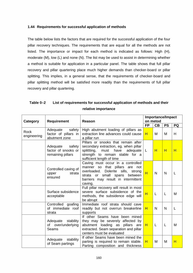
160
1.44 Requirements for successful application of methods
The table below lists the factors that are required for the successful application of the four
pillar recovery techniques. The requirements that are equal for all the methods are not
listed. The importance or impact for each method is indicated as follows: High (H),
moderate (M), low (L) and none (N). The list may be used to assist in determining whether
a method is suitable for application in a particular panel. The table shows that full pillar
recovery and pillar quartering place much higher demands than checker-board or pillar
splitting. This implies, in a general sense, that the requirements of checker-board and
pillar splitting method will be satisfied more readily than the requirements of full pillar
recovery and pillar quartering.
Table 0–2 List of requirements for successful application of methods and their
relative importance
Category Requirement Reason Importance/Impact on metod FP CB PS PQ
Rock engineering
Adequate safety factor of pillars in abutment zone
High abutment loading of pillars as extraction line advances could cause a pillar run
H M M H
Adequate safety factor of snooks or remaining pillars
Pillars or snooks that remain after secondary extraction, eg. when pillar splittting, must have adequate strength to remain stable for a sufficient length of time
L H H H
Controlled caving of upper strata ensured
Caving must occur in a controlled manner so that pillars are not overloaded. Dolerite sills, strong strata or small spans between barriers may result in intermittent caving.
H N N L
Surface subsidence acceptable
Full pillar recovery will result in most severe surface subsidence of the methods, the subsidence edge will be abrupt
H L L M
Controlled goafing of immediate roof strata
Immediate roof strata should cave readily but not overrun breakerline supports
H N N L
Adequate stability of over/underlying Seams
If other Seams have been mined they may be severely affected by abutment loading as pillars are extracted. Seam separation and pillar centers must be evaluated
H L L M
Adequate stability of Seam partings
If other Seams have been mined the parting is required to remain stable. Parting composition and thickness
H M M H

161
must be evaluated
System stiffness adequate
If yielding pillars are left the loading system stiffness must be adequate to ensure non-violent yield. This is affected by barrier spacing.
N M M H
Adequate roof strength
Large spans are created when pillars are removed, spans must remain stable during operations
M H M M
Controlled yield of remaining pillars over long term
Over loaded remaining pillars will ultimately fail, they should do so in a controlled manner. The width to height ratio of remaining pillars
N M M H
Mining Ability to provide breakerline/ fingerline supports
Roofbolt or timber breakerlines are required, Seam height or roof condition may preclude installing breakerlines
H N N L
Ability to control direction of pillar splitting
Pillar splitting direction relative to geological structures and field stress impacts the local roof stability
H L L M
Training and experience
Pillar extraction requires special skills and experience with local conditions. Miners need to be familiar with roof behaviour and goafing characteristics
H M L H
Safety of employees
Safety is compromised if employees work near goaf H N N M
Environ-mental
Groundwater disturbance
Groundwater is disturbed by creation of cave fractures and subsidence H M M H
Subsidence limitations
The severity of subsidence varies according to the amount of coal extracted. The surface environment may be affected by subsidence.
H L L M
Spontaneous combustion
Formation of snooks and crushing coal may result in spontaneous combustion
H L L H
Beneficiation
Ability to accommodate dilution
Mining adjacent to goaf results in higher quantity of waste rock in coal H N N L
1.45 Checklist of requirements against panel constraints
When deciding on a mining method for a particular panel, the first objective will be to
determine whether the constraints associated with the panel eliminate any of the methods.
Before the checks can be carried out, data regarding the panel must be collected and
several basic calculations must be carried out. Table 0–3 shows the factors that must be
considered, a space has been left open to fill in the constraint posed by the panel and four
columns to indicate whether the different methods satisfy the constraints. An example of a
hypothetical panel assessment is presented as Table 0–4.

162
The example shows that full pillar recovery and pillar quartering are both eliminated, since
they do not satisfy a number of the constraints imposed by the panel. This first stage
elimination will reduce the number of options that need to be considered during the
method selection process.
The data collection and studies required to evaluate the different mining methods are
summarized in Table 0–5. For example, pillar and snook safety factors, roof stability,
mining costs and environmental assessments have to be done to determine what the
constraints are. The technology to determine some of the answers that the studies have to
provide are not well developed, such as deciding how well a roof stratum will goaf. Further
research into using roof rating systems may be required. Several of the other aspects will
benefit by further research.
Table 0–3 Checklist to determine if mining methods are eliminated by panel
constraints
Category Requirement Panel constraint Does method satisfy
constraint? FP CB PS PQ
Rock Eng Surface subsidence Middling stability Pillar superposition Factor of safety of
pillars in other Seam
Factor of safety of snooks
Factor of safety of pillars in abutment zone
Controlled goafing of immediate roof
Controlled caving of upper strata
System stiffness adequate
Roof strength adequate Long term yield of pillars Mining Coal recovery
requiremnt
Ability to provide breakerlines
Acceptable mining cost Control direction of pillar
splitting
Training and experience
Safety next to goaf satisfactory
Environ- Groundwater

163
mental disturbance Subsidence effect on
environment
Spontaneous combustion
Beneficiation Accommodate dilution
Table 0–4 Example of panel and mining method assessment
Category Requirement Panel constraint Does method satisfy constraint? FP CB PS PQ
Rock Eng. Surface subsidence Must be < 1m N Y Y N Middling stability Middling 4.5m Y Y Y Y Pillar superposition Pillar centres 15m N Y Y N Factor of safety of pillars in
other Seam FOS 1.66 Y Y Y Y
Factor of safety of snooks Seam height 2.1m pillars 9m
- Y Y Y
Factor of safety of pillars in abutment zone
Current FOS 1.5 N Y Y Y
Controlled goafing of immediate roof
2m thick sandstone N - - N
Controlled caving of upper strata
No dolerite sills or thick sandstone beams
Y - - Y
System stiffness adequate 15m wide barriers 120m apart
Y Y Y N
Roof strength adequate 2m thick sandstone Y Y Y Y Long term yield of pillars High system stiffness - Y Y Y Mining Ability to provide
breakerlines Seam height 2.1m OK Y Y Y Y
Control direction of pillar splitting
Major joints run NW/SE can split perpendicular to this direction
Y Y Y Y
Recovery acceptable Must recover more than 50% of pillars to be viable
Y Y Y Y
Mining cost acceptable Not cost sensitive Y Y Y Y
Training and experience Have teams experienced in pillar extraction
Y Y Y Y
Safety next to goaf satisfactory
Goaf will break in large slabs – safety an issue
N Y Y N
Environ-mental
Groundwater disturbance No problems foreseen - - - -
Subsidence effect on environment
Erosion if subsidence exceeds 1m
N Y Y N
Spontaneous combustion Coal relatively inert Y Y Y Y Beneficiation
Accommodate dilution No washing plant – dilution must be limited
Y Y Y Y
Table 0–5 Studies and data collection required to evaluate method requirements

164
Category Requirement Evaluation method
Rock Eng. Surface subsidence Empirical subsidence prediction methods of Schumann and Wagner or use local records if available
Middling stability Salamon’s guidelines, or use local experience if available
Pillar superposition Salamon’s guidelines, or use local experience if available
Factor of safety of pillars in other Seam
Salamon’s guidelines, or use local experience if available
Factor of safety of snooks Numerical modelling or empirical guidelines based on local experience
Factor of safety of pillars in abutment zone
Numerical modelling and pillar strength equations
Controlled goafing of immediate roof
Roof stability index (?) Coal Mine Roof Rating
Controlled caving of upper strata
Geological assessment, dolerite sill evaluation and previous experience
System stiffness adequate Numerical modelling, possibly, Ryder’s BEPIL program
Roof strength adequate for large spans
Geological assessment of roof laminations, CMRR and previous experience
Long term yield of pillars Stiffness assessment and consideration of w:h ratio of pillar. Numerical models.
Mining Ability to provide breakerlines
Consideration of practicality of installing breakerlines, mechanical breakers, bolts etc.
Control direction of pillar splitting
Consideration of ability to split pillars in a favourable direction
Training and experience Consideration of ability of mining team, past experience and whether training can be done.
Safety next to goaf satisfactory
Consideration of likely predictability of goaf and goaf overruns, whether it can be controlled
Environ-mental
Groundwater disturbance Groundwater investigation
Subsidence effect on environment
Environmental impact assessment
Spontaneous combustion Coal combustion testing Beneficiation
Accommodate dilution Consideration of beneficiation process, washing plant and market requirements
1.46 Decision support system to select best mining method
The mining methods that survive the initial screening should be subject to a selection
process that will indicate which is the best method. The application of the Analytical
Hierarchy Process (AHP), as developed by Saaty (1994), has been used as a basis for
the selection process. The AHP process was developed as part of the United States Arms
Control and Disarmament Agency in the nineteen sixties to facilitate decision making

165
when one is faced with complex interrelated problems. The AHP process is simple in its
fundamental premise that only two alternatives are compared at a time against a given
criterion. The process is repeated for all alternatives and all criteria. The judgements are
summed to identify the best alternative.
1.47 Outline of decision process
The outline of the AHP process may be summarized as shown in Figure 0–1. The goal of
finding the best method is set. Below the goal, the criteria are subdivided into disciplines.
The relative weighting of each criterion is determined using pairwise comparisons. Finally
the alternative methods are evaluated, using pairwise comparisons against each of the
criteria. The outcomes are manipulated mathematically to provide the best solution.
The method has been programmed into a spreadsheet, so that users do not need to carry
out the calculations themselves. The spreadsheet program is specifically designed to
evaluate the problem of mining method selection, using the criteria listed above.
Figure 0–1 Outline of analytical hierarchy process for selecting best method
GoalBest mining method
Mining BeneficiationEnvironmentalRock mechanics
•Cost•Safety•Recovery•Splitting direction•Training & experience•Breakerlines•Adaptable to conditions•Dilution•Equipment adequate•Regulations•Capital requirments
•Surface subsidence•Pillar stability•Snook stability•Snook failure•System stiffness•Goaf control•Caving of upper strata•Middling stability•Adjacent seam workings•Roof strength
•Surface subsidence•Groundwater•Closure issues
•Dilution•Size distribution
Full pillar recovery Checkerboard Pillar splitting Pillar quartering

166
1.48 Example of application of AHP spreadsheet to evaluate suitability of mining
methods
As an example, the AHP spreadsheet was used to evaluate the four mining methods
under consideration for two hypothetical panels. The first panel (A) is a single Seam
extraction with the following general limitations:
The mine employees are accustomed to pillar splitting but have never done full pillar
recovery before.
The immediate roof is strong and there is concern that it will not goaf readily, but is
expected to stand up over extended spans.
Previous pillar extraction trials showed that snooks tended to fail violently and
unexpectedly.
A dolerite sill in the upper strata will fail intermittently, causing high abutment stresses.
Surface subsidence of up to 2m is tolerable.
The mine has a washing plant and dilution of the coal is not a major concern.
The main concerns are therefore related to panel stability issues, followed by operational
concerns related to the lack of experience of the employees in three of the mining
methods. The environmental and beneficiation issues are lesser concerns.
The AHP spreadsheet was used first to rate the relative importance of the four main
criteria for selecting a mining method. The results are presented in Figure 0–2, which
shows the relative importance of the criteria after rating their relative importance using the
AHP process. The importance of stability and operational criteria are clearly highlighted.
These relative priorities are used to weight the importance of the sub-criteria associated
with each criterion.
After rating the importance of the main criteria, all the sub criteria were assessed. During
this assessment the limitations imposed by the panel are borne in mind when assigning
priorities. The results are summarized in the figures on the next few pages. The results
are specific for the panel and other evaluators will produce a different set of priorities. The
priorities assigned by several knowledgeable persons may be combined in the
spreadsheet.
Figure 0–3 shows that mining cost, safety and the ability to satisfy regulations are the
main operational concerns, followed by concern over the training and experience of the

167
mining crew. The results in Figure 0–4 show that roof stability, failure of snooks, stability
of pillars at the extraction line and goaf control are the main stability concerns.
Figure 0–2 Relative importance of criteria for hypothetical Panel A
The relative priority of the environmental and beneficiation concerns are shown in Figure
0–5.
Figure 0–3 Relative importance of operational issues for hypothetical panel A
Importance of main criteria
0.00 0.10 0.20 0.30 0.40 0.50 0.60
Operational issues
Stability aspects
Environmental impact
Beneficiation issues
Priority
Importance of operational issues
0.00 0.05 0.10 0.15 0.20 0.25
Mining operational cost
Safety in the panel
Recovery of the coal
Ability to split pillars in required direction
Training & experience of crew
Ability provide breakerline supports
Adaptable to f loor & roof conditions
Ability to limit dilution
Available equipment is suitable
Satisfy regulations
Reduced capital requirements

168
Figure 0–4 Relative importance of stability considerations for hypothetical panel
A
Figure 0–5 Relative importance of environmental and beneficiation issues for
hypothetical Panel A
Importance of stability criteria
0.00 0.05 0.10 0.15 0.20 0.25
Stability of pillars at extraction line
Controlled snook failure
Snook failure mode
Sensitivity to system stif fness
Goaf control
Loading by upper strata
Middling stability
Other seam stability
Roof stability
Priority
Importance of environmental issues
0.00 0.05 0.10 0.15 0.20 0.25 0.30 0.35 0.40 0.45 0.50
Limit subsidence
Groundwater issues
Mine closure issues
Importance of beneficiation issues
0 0.1 0.2 0.3 0.4 0.5 0.6 0.7 0.8
Dilution of coalproduct
Size distribution ofcoal product

169
Figure 0–6 Final priorities of mining methods for hypothetical Panel A
The four mining methods were then compared, two at a time, for each of the sub-criteria
and the final priorities shown in Figure 0–6 were obtained. The results show that pillar
splitting has the highest priority, followed almost equally by pillar quartering and the
checker-board method.
The priorities of the methods for the second panel, Panel B, were also determined. For
this hypothetical case, the difference between the two panels was assumed to be as
follows:
• a stream runs over the panel and the subsidence limit is reduced to 0.5m and
groundwater disturbance is a major problem, the environmental issues are therefore
very important.
The priorities of the main criteria were re-calculated for Panel B, resulting in the relative
priorities shown in Figure 0–7, which shows how the priority of environmental issues has
increased. The change in priorities of the main criteria resulted in the method priorities
shown in Figure 0–9.
Priority of methods
0.00 0.10 0.20 0.30 0.40
Full pillar recovery
Checkerboard
Pillar splitting
Pillar quartering
Priority

170
Figure 0–7 Relative importance of criteria for hypothetical Panel B
Figure 0–8 Priorities of mining methods for hypothetical Panel B
The results show that the checker-board method now becomes the most favourable
method, mainly because it will result in the least surface subsidence. Note that the new
priorities were obtained without re-evaluating all the methods and sub-criteria, only the
relative priorities of the main criteria were changed.
Importance of main criteria
0.00 0.20 0.40 0.60 0.80
Operational issues
Stability aspects
Environmental impact
Beneficiation issues
Priority
Priority of methods
0.00 0.10 0.20 0.30 0.40 0.50 0.60
Full pillar recovery
Checkerboard
Pillar splitting
Pillar quartering
Priority
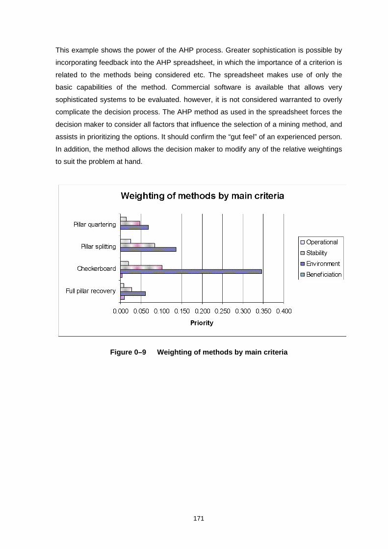
171
This example shows the power of the AHP process. Greater sophistication is possible by
incorporating feedback into the AHP spreadsheet, in which the importance of a criterion is
related to the methods being considered etc. The spreadsheet makes use of only the
basic capabilities of the method. Commercial software is available that allows very
sophisticated systems to be evaluated. however, it is not considered warranted to overly
complicate the decision process. The AHP method as used in the spreadsheet forces the
decision maker to consider all factors that influence the selection of a mining method, and
assists in prioritizing the options. It should confirm the “gut feel” of an experienced person.
In addition, the method allows the decision maker to modify any of the relative weightings
to suit the problem at hand.
Figure 0–9 Weighting of methods by main criteria

172
Conclusions and recommendations
Investigations into the importance of secondary extraction indicated that for the period
1970 to 1997, 1.68 billion tons of coal lock in more than 1.7 million coal pillars was left
underground. This covers an area of 27 x 27 km (729 km2). This means that sufficient coal
is left in the pillars to sustain ROM production for 17 years, excluding barrier pillars.
However, given the current assumptions, its appears that the application of pillar
extraction is significantly smaller than what was previously believed. This is however
caused by the specific assumptions used in this project. Improvement in the percentage
extraction with adjustments made to the Nevid method for shallower depths will
dramatically improve the situation. Extracting the barrier pillar between adjacent panels
together with the adjacent pillars left to create the bleeder road will also make a significant
difference as is the case at some existing operations. Carrying the water treatment cost
well beyond the life of the mine will worsen the situation. With this in mind, and the fact
that we are utilizing a diminishing resource which should be exploited to its full,
tremendous effort should be put into water management to improve water quality. This
should be backed by an even more dedicated research effort in finding more economic
water treatment technologies, both from a capital and operating cost point of view.
Considering ashfilling, it should be realized that given the requirement of strength and
stabilizing properties, it is highly unlikely that suitable ash mixtures can be developed
within the cost framework.
Detailed literature review highlighted that various pillar extraction methods are applied
successfully on a worldwide front. These methods include both methods for the secondary
extraction of previously mined pillars as well as “pillars” designed and developed for
immediate extraction such as the typical rib pillar methods.
It is critical to take note of the various constraints affecting successful pillar extraction both
during the design phase as well as in the evaluation of previously mined pillars. Although
it is well known that due to the dynamic nature of pillar extraction, and awareness of
danger involved in pillar extraction, limited study into the investigation of falls of ground
fatalities in South Africa indicated that pillar extraction is the least safe mining practice
(Vervoort [1990], Canbulat and Jack [1998]).

173
Although the database was small and consequently the correlation low, the following
conclusions were nevertheless drawn from the site visits:
a) The initial safety factor of the pillars has a major effect on the pillar conditions
during pillar extraction, specifically near the stooping line.
b) The pillar conditions at the stooping line tend to deteriorate more rapidly as the
age of the pillars being extracted increases.
c) Mine personnel working with pillar-extraction panels do not perceive the age of the
workings as contributing to the hazard of pillar extraction.
d) About 40 per cent of the tonnage mined at the time had been produced from
panels older than three years or with a safety factor of less than 2.0.
Site visits highlighted that except for the Tshikondeni Colliery and the Sasol mines, all the
mines were mining previously developed sections whose panels were not originally
designed for total extraction mining methods.
It was also apparent that the mining method employed, and especially the pillar mining
sequence, was site-specific. As such, the design and the mining methods used were
specifically adapted to suit local mining and geological conditions.
In all the feedback received it was claimed that this method of mining was as safe as or
even safer than normal bord-and-pillar development.
It was further evident that extraction efficiency (of single pillars) is site and operator-
specific. The final extraction efficiency is normally a matter of judgement on the part of the
operator.
There was no difference in coal quality except in panels where high levels of oxidation
were reported.
It was reported by the mines that the cost of later pillar extraction is generally lower than
the development cost when pillar extraction follows directly after pillar development. This
lower cost is most probably the result of lower support requirements during secondary
extraction. However, where extensive clean–up of old panels has to be done along with
the provision of extensive additional roof support and the installation of support services,
the cost of pillar extraction increases.

174
It is concluded that a qualitative and quantitative approach to site inspections prior to the
opening of an old mined-out bord-and-pillar section is critical. It was generally felt that
detailed decision-making about the method to be employed was only possible after a
thorough in-section evaluation of the reserves available and the prevailing mining and
panel conditions had been done.
Review of current pillar extraction practices showed that pillar extraction takes many forms
and mines have adopted methods of removing individual pillars to suit their particular
needs. In ‘traditional’ stooping, it was recommended practice to remove or destroy all
snooks in order to allow the goaf to cave thereby relieving the stress on the caving pillar
line. Many of the pillar extraction methods now used deliberately leave pre-designed
snooks that prevent immediate caving but will crush over time.
One major disadvantage of keeping up the goaf by the use of pre-designed snooks or by
the use of checker-board mining is the uncertainty of when the snooks or remaining pillars
are going to crush and allow the overburden strata to settle.
Contrary to previously held views, mines now do not believe that pillar extraction is a less
safe method than pillar development. This may be because pillar extraction is now done
by continuous miner, often by means of remote control, and also that the incorporation of
section employees in more risk assessment procedures has introduced a greater
awareness amongst the underground operators of the inherent dangers in pillar
extraction. Also, more use is now made of ‘partial’ pillar recovery and checker-board
systems where the formation of a goaf edge is prevented, thereby removing a hazardous
area from the system.
The cost of pillar extraction in comparison to pillar development is reported to be higher by
some mines but lower by others. Much depends on a mine’s costing procedures and
whether pillar extraction follows directly after pillar development or whether old panels
have to be rehabilitated.
Pillar extraction by means of shortwall equipment has been done successfully but a
particular problem can be the rate of retreat through the pillars. Careful consideration must
be given to the logistics of utilising what is considered to be a highly capital intensive
method for the recovery of pillars.

175
The recovery of old pillars by underground pillar extraction was shown to be feasible in the
No 4 Seam and the No 2 Seam in the Witbank Coalfield. Experience is being gained
which should be beneficial to the industry in the wider application of pillar extraction to
other parts of the Coalfield where suitable reserves may be found.
This study highlighted that the so-called Nevid Method has a potential for future pillar
extraction in South Africa. However, currently, it cannot be applied at shallower depths
because of pillar dimensions required. It is therefore a study was conducted to determine
the extraction dimensions, lift widths and safety factors for NEVID pillars at various
depths. The results are presented below.
Depth ctr ctl cb lw A Q SF
160 6.0 2.0 5.0 7.2 140.9 96.7 0.35
140 5.0 3.0 5.0 6.0 107.5 84.6 0.37
120 4.0 2.0 4.0 5.0 78.7 77.1 0.36
100 3.0 2.5 3.0 4.5 53.0 59.1 0.35
80 2.4 2.4 2.5 3.6 36.0 47.5 0.35
The importance of panel width was also shown with this study. Leaving artificial barrier
pillars was recommended if the safety factors of the pillars being extracted small and the
panel is too wide.
It is recommended that a decision making process for pillar extraction should follow a flow
sheet analysis. In general, five important evaluations were found to be considered. These
are:
• Rock engineering evaluation
• Environmental risk evaluation
• Mining evaluation
• Coal beneficiation, and
• Financial evaluation

176
All these factors have their own constraints and limitations. It is therefore decided to
develop flow sheets for the above given evaluations.
This study also indicated that selection of the mining method is very important. It is
therefore a mining method selection methodology was developed. The following methods
of coal pillar recovery were considered.
• Full pillar recovery in which all the pillars are recovered using typical pillar extraction
methods;
• Checker-board pillar recovery: in which every second pillar is recovered;
• Pillar splitting: every pillar is split into two smaller pillars by driving a roadway through
the pillar;
• Pillar quartering: every pillar is split into four smaller pillars by driving two roadways at
right angles through the pillar.
In order to select the best method, the differences between the methods were first listed,
under the topics of rock engineering, mining, environmental and beneficiation. Similarities
between the methods were ignored, since they would apply equally to all the methods,
and would not play a role in selecting a particular method above another.
Once the differences were identified, the requirements for success of the methods were
listed, based on the differences. These lists formed the basis for drawing up a checklist
that may be used to assess the applicability of each mining method to a particular panel.
This process allows unsuitable methods to be eliminated. If more than one mining method
survives the checking process, a decision support system may be used to select the best
method. The decision support system is based on the Analytical Hierarchy Process
developed by Saaty (1994). A spreadsheet has been developed which uses the list of
differences between the methods to evaluate their suitability for a given situation.
Finally, it is strongly recommended that the methods and guidelines given in this project
should be applied in an actual pillar extraction project in order to determine the
applicability of them.

177
References
Anonymous (1990) Thin-seam mining, Colliery Guardian, February, pp 45-47.
Anonymous (1999) Statistical summary of accidents reported to the Chief Inspector of
Mines for the period 1 January 1984 to 31 December 1998, Department of Minerals and
Energy, Pretoria.
Basu, K. (1999) My research, http://fbox.vt.edu:10021/K/kbasu/research.html, 6 October.
Baxter, R., (1998). Coal production in South Africa - an overview 1997. Coal International
May 1998. pp 106 -100.
Beukes, JS.(1989) Stooping practices in South African collieries, Part 1: Rib pillar
extraction, Chamber of Mines of South Africa, Report No. 3/89.
Blaiklock, J (1992) A Kentuckian vote for continuous mining, Mining Magazine, June, pp
365-366.
Bryan, A, Bryan, JG and Fouche, J (1964) Some problems of strata control and support
in pillar workings, The Mining Engineer, London, Vol. 123, pp. 238-254.
Canbulat, I. and Jack, B.W. (1998) Review of current design methodologies to improve
the safety of roof support systems, particularly in the face area, in collieries. SIMRAC
Final Project Report, COL 328, December.
Canbulat, I and Johnson, R. (2002) Anglo coal pillar extraction project: pre-feasibility
modelling. Confidential Consultancy Report. March. Report No: JP-011-01-2002
Chase, FE, McComas, A, Mark, C and Goble, CD (1997) Retreat mining with mobile
roof supports, Proceedings: New Technology for Ground Control in Retreat Mining,
http://www/cdc.gov/niosh/97-133.html, 8 January.
Clark, J and Caldon, JH (1982) Thin seam coal mining technology, Noyes Data
Corporation, New Jersey, USA.

178
De Beer, JJS, Hunter, F and Neethling, AF (1991) Rib-pillar mining at Sigma Colliery,
Journal of the South African Institute of Mining and Metallurgy, Vol. 91, No. 6, June, pp
209-218.
Falconer, KW (1989) A review and cost comparison of the three main methods of
underground coal mining in South Africa, MSc Thesis, University of the Witwatersrand,
Johannesburg.
Galvin, JM, Hebblewhite, BK and Salamon, MDG (1997) Australian coal pillar
performance, Australian Mining, pp 33-38.
Gericke, P (1989) The evolution of total extraction technology as applied by Middelbult
Colliery, SAIMM School: The Total Utilisation of Coal Resources, Vol. 1, Witbank.
Hardman, D.R., (1989). The consequences of leaving vast mined-out areas standing on
pillars. In: Total Utilization of Coal Resources, SAIMM School, Witbank.
Heasley, KA (1997) A new laminated overburden model for coalmine design,
Proceedings: New Technology for Ground Control in Retreat Mining,
http://www/cdc.gov/niosh/97-133.html, 8 January.
Jefrey, L.S., (2000). Literature review – Current status of resources and reserves in the
Northern Witbank-Highveld coalfield, subtask 2 draft report, Coaltech 2020.
Landman, GVR (1987) Thin seam extraction at the Durban Navigation Collieries, MSc
Thesis, University of the Witwatersrand, Johannesburg.
Langdon, B (1998) Coal mine support: Conceptual leaps or pragmatic steps? Journal of
the Institute of Mining and Metallurgy, December, pp 325-330.
Lind, GH (1999) The development of a costing framework to compare two types of
underground mining methods in a typical South African coal mine for use in decision
making, MSc Thesis (Project Report), University of the Witwatersrand, Johannesburg.
Livingstone-Blevins, G and Watson, S (Eds) (1982) Pillar extraction, Chamber of Mines
of South Africa, Report No. NS 469, Johannesburg.

179
Madden, BJ (1987) The effect of mining method on coal pillar strength, Chamber of
Mines of South Africa, Research Report 15/87, Johannesburg.
Madden, BJ (1988) ‘Squat’ pillar design, Coal International, Vol. 7, No. 1, January, pp 6-
9.
Madden, BJ (1989(a)) Squat pillar design in South African collieries, SANGORM
Symposium: Advances in Rock Mechanics in Underground Coal Mining, September, pp
83-90.
Madden, BJ (1989(b)) Reassessment of coal pillar design, SAIMM School: The Total
Utilisation of Coal Resources, Vol. 1, Witbank.
Madden, BJ (1990) The ‘Squat” pillar design formula and some advantages of its
application, South African Colliery Managers’ Association (SACMA), Papers presented
1984 - 1988, Chamber of Mines of South Africa, pp 205-229.
Madden, B.J., Canbulat, I., Jack, B.W. and Prohaska, G.D., (1995). A reassessment of
coal pillar design procedures, SIMRAC Final Project Report – COL021, CSIR-Division of
Mining Technology, December.
Madden, BJ and Canbulat, I (1996) Reassessment of coal pillar design procedures,
CSIR Miningtek Report No. NS 1479, Johannesburg.
Madden, BJ (1997) Current and future risks and casual issues relating to rock
engineering on South African coal mines, Final Project Report No. SIMRISK 401,
SIMRAC, Johannesburg.
Mark, C and Chase, FE (1999) Analysis of retreat mining pillar stability (ARMPS),
Proceedings: New Technology for Ground Control in Retreat Mining,
http://www/cdc.gov/niosh/97-133.html, 8 January.
Mark, C, Chase, FE and Zipf, RK (1999) Preventing massive pillar collapses in coal
mines, Proceedings: New Technology for Ground Control in Retreat Mining,
http://www/cdc.gov/niosh/97-133.html, 8 January.

180
Mark, C, McCall, FE and Pappas, DM (1999) A statistical overview of retreat mining of
coal pillars in the United States, Proceedings: New Technology for Ground Control in
Retreat Mining, http://www/cdc.gov/niosh/97-133.html, 8 January.
Marx (1996) An Activity Based Costing Approach to Fall of Mine Accidents in a South
African Gold Mine, Project Report, Potchefstroom University, Potchefstroom.
McCosh et al (1989) Stooping with roofbolt breakerlines on the Alfred seam, SACMA
papers 1984-1988, pp 389-404.
Minerals Bureau, (1989, 1990, 1991, 1992, 1993, 1994, 1995, 1996, 1997). Operating
and developing coal mines in the Republic of South Africa.
Oberholzer, J.W., et al., 1997. Determine the need to research the time related stability
decay of bord and pillar systems, SIMRAC Final Project Report – COL 439, CSIR-Division
of Mining Technology.
Plaistowe, RHA, Poultney, MO, van Schalkwyk, B, Hichens, RL and Bradbury, TJ
(1989) Decision-making considerations for pillar extraction, SAIMM School: The Total
Utilisation of Coal Reserves, Vol. 1, Witbank.
Rogers, PR (1989) Rib pillar extraction at New Denmark Colliery, SAIMM School: The
Total Utilisation of Coal Resources, Vol. 1, Witbank.
Ryder, J.A. (1992) Determination of the quatity of ashfill required to stabilize and prevent
undue subsidence of old workings. CSIR Internal Report. Report No: B03/92. October
1992.
Salamon, MDG (1967) A method of designing bord and pillar workings, Journal of the
South African Institute of Mining and Metallurgy, Vol. 68, pp. 55-67.
Salamon, MDG and Munro, AH (1967) A study of the strength of coal pillars, Journal of
the South African Institute of Mining and Metallurgy, Vol. 68, pp. 68-78.
Salamon, MDG and Oravecz, KI (1973) Rock mechanics in coal mines, Chamber of
Mines of South Africa Research Organisation, Project Report No. CM/807/66.

181
Salamon, MDG and Wagner, H (1985) Practical experiences in the design of coal pillars,
Miningtek Report NS 584.
Schumann, EHR (1982) Controlled subsidence of the Blackhill-Greenside railway line:
Part 1, Chamber of Mines Research Organisation, Research Report No. 8/83,
Johannesburg.
Steart (1954) Strength and stability of pillars in coal mines, Journal of the Chemical,
Metallurgical and Mining Society of South Africa, March, pp. 309-325.
Strata Engineering (Australia, 2002). Initial Assessmnet of the Geotechnical Constraints
to Undertaking Pillar Extraction Operations in Existing Bord and Pillar Workings
Containing “Small” Pillars. Confidential Consultancy Report to Anglo Coal. Report No: 01-
183-AAC/1. January.
Skybey, G (1982) Geotechnical evaluation of Wongawilli extraction system at Coalcliff
Colliery, Australian Coal Industry Research Laboratories Ltd, Published Report 82-11.
Vervoort, A (1990a) Falls of ground in South African collieries during the period 1970-
1988, Part I: Review of fall of ground fatalities and injuries, Reference Report No. 5/90,
COMRO, Johannesburg.
Vervoort, A (1990b) Falls of ground in South African collieries during the period 1970-
1988, Part II: Description of fatal falls of ground, Reference Report No. 6/90, COMRO,
Johannesburg.
Vervoort, A (1990c) Falls of ground in South African collieries during the period 1970-
1988, Part III: Effect of exploitation method, Reference Report No. 7/90, COMRO,
Johannesburg.
Vervoort, A & Prohaska, G (1991) Dynamic roof movement in intersections during pillar
extraction, Mining Science and Technology, vol. 13, Amsterdam, pp. 351-357.
Wagner, H (1981) An investigation of pillar extraction systems to improve percentage
extraction in South African collieries, Coal Symposium, Pretoria, 11 May.

182
Wagner, H and Madden, BJ (1984) 15 Years Experience with the design of coal pillars in
shallow South African Collieries, ISRM Symposium, Cambridge, U.K., 3-6 Sep ’84, pp
391-399
Walker (1995) Behind the miner, World Mining Equipment, vol. 19, No. 4, May 1995, pp6-
8, 10-11.
Willis, RPH and Hardman, DR (1997) Projections of likely changes in mining
circumstances, conditions and technologies which may affect safety and health risks,
Final Project Report No. SIMRISK 401, SIMRAC, Johannesburg.
York,G et al. (1998) Develop guidelines for the design of pillar systems for shallow and
intermediate depth, tabular, hard rock mines and provide a methodology for assessing
hangingwall stability and support requirements for the panels between pillars. SIMRAC
report GAP 334. CSIR, Division of Mining Technology.

183
Appendix 1: Comparison of Geometry and Resources
Approx. Output
Colliery Seam Depth (m)
Thickness (m)
Extraction Height (m)
Pillar Width (m)
Bord Width (m)
S.F. Age of Panels
Panel Width (m)
Equipment Section Labour
Ton Per Shift
Ton Per Month
Greenside No. 5 30 - 60 1.8 1.8 8.5 7.5 1.8 +/- 13 170 to 200
Joy 12CM6 + 8t S/cars
18 860 19000
New Clydesdale No. 2 50 - 70 +/- 4 3.6 8.5 7.5 1.8 +/- 20 170 to 200
Joy HM9+ 8t S/cars
14 950 38000
Gloria X No. 2 150 5 4.5 - 5.0 21 7 1.8 7 175 Joy HM17+ 18t S/cars
12 1200 50000
Blinkpan X No. 2 80 4.2 4.2 12.2 6.8 1.7 +/-3.5 121 Joy HM9+ 10t S/cars
16 911 44500
Arthur Taylor No. 4 63 4.2 3.2 10.5 6.5-7.5 2 4 210 Joy HM31+ 16t haulers
19 1125 49600
Boschman's No. 4 60 +/- 5 3.8 10.5 6.5 1.8 2 160 Joy HM31+ 10t S/cars
15 1136 50000
Twistdraai No. 4 160 3.5 3.5 18 6.5 - 7 1.8 +/- 1 150 Joy HM31+ 16t Sascars
11 44000
New Denmark # No. 4 200 1.8 1.8 18 7 2 4 75 Shearer - 848 44433
DNC U & L 250 3.1 - 3.8 3.1 - 3.8 25 4.5 - 5 1.7/2.1 +/- 5 215 VA AM75+ 10t S/cars
15 750 30000
ZAC 1 X M 232 1.45 1.45 10.4 6.6 1.8 0.5 - 3 74 Joy + 4t TT units
13 434 17653
ZAC 2 X M 110 2.3 2.3 13.6 6.4 2.36 0.5 - 3 86 AM 75 + 8t Wagners
15 520 23019
X Checker-board # Shortwall pillar extraction

184
Appendix 2: Geology and support efficiency
G/side NCC Gloria B/pan ATC B/mans T/draai N.
Denmark
DNC ZAC 1 ZAC 2
Sill thickness (m) N/A N/a N/A 9 to 18 N/A N/A 8 N/A 90 5.7 1.7 & 3.9 Distance to sill N/A 50 N/A N/A 30 N/A 95 13 13 & 16 Immediate roof? And thickness
coal/shale coal, 0.5 coal,1.2m coal,+/-1m sh/sst,.4/.6m
sandstone shale 9m sst 7.1m sst
Immediate floor? And thickness
sandstone sandstone shaley/sst 18m sst mic sh,mudst
sandstone shale 0.8m sst & sh
0.6m sh
Roof and support conditions
Roof competence Fair/good
varies good good good in roads
good good good excellent
Roof fall: density and height? shale & slips
none none none sporadic sporadic upto 5m,5/pa
none none
Support type Resin r/b
1.5m mech, 1.5m M16 resin,2m M20 resin
roofbolts resin roofbolts
resin roofbolts
full col resin, 20mm rebar
roofbolt mech,resin & cable anchor
no syst. support
no syst. support
Support efficiency good - good good good - good inefficient good good Support pattern 3/row,2m
between rows
2 bolts/row 5m apart, 2m row spacing
2 bolts/row, 2.5m spacing
1.2mspacing
2 bolts every 1m
4 bolts every 3m
2m x 2m 1.5 m in all directions
depends on conditions
no syst. support
Installation of support Roofbolter
Roofbolter Roofbolter Roofbolter roofbolter roofbolter wombat Roofbolter roofbolter roofbolter
Type of support failure?
none Mech slip none none none none sporadic Frittering none none
Support length(m) 1.5 2m resin at slips, 6m cables
1.5m & 1.9m
1.2 m 1.2m 1.2 m 1.5 m 1.8m bolts 5m anchors
0.5 & 0.9 m varies
Current support conditions N/A moderate good good good good N/A good good Additional information

185
Discontinuities in the roof and pillars
none minor at +/- 200m
none none some faulting
minor none none yes yes
Pillar punching none none none none none none none limited none some areas
some areas
Any weakness in pillar none none slips in pillars
none yes none none none shale parting
none none
Roof pillar contact good coal roof
coal coal good coal - good - good good
Pillar fracturing very little
little at slips/dykes
minimal at delayed goafing
minimal none minor scaling
yes yes yes
Top/bottom coaling none none none none none none none none none none none Presence of slips And/or faults
very few plenty yes stringers /slips
none occasional sporadic none none yes yes
Presence of stone Or shale layers
None sst band + floating stone
some areas
shale in roof
.3-.4m shale layer
shaley sst band 3m from floor
floating st. none Yes yes yes

186
Appendix 3: Miscellaneous
G/side NCC Gloria B/pan ATC B/mans T/draai N. Denmark
DNC ZAC 1 ZAC 2
Problems Cleaning & Re-support Old areas
Clean,support, make safe & ventil.
Mining pillars which have slips
none none none Scaling & slabbing in high Seams
Panels limited to 75 m in width
Excessive sidewall failure
None none
Solutions mine 90o to slip
N/A N/A N/A ? - s/w support
N/A N/A
Change in coal quality? none not known none none none none less dirt more dirt none None none Change in coal size? bigger bigger +/- 5%
larger none none bigger none none none Bigger bigger
Surface disturbance yes yes none none yes yes yes yes none None yes Subsidence extent - - N/A N/A - whole
panel limited little none N/A Minimal
Subsidence magnitude 50% of h +/-1.2m N/A N/A 1.5m 1m to 3m ? 0.8 m none N/A Minimal Water table effect yes yes N/A none none yes yes yes none Yes Yes Spon. com problems? none none none none none none none none yes None None Methane problems minor minor none none none none yes yes yes None None Airflow problems none none none none none yes yes yes none None None Problems with geotech/geol.
none none none none none none none none none None None
Pillar/panel behaviour? - - - - - - - - - Stable Stable Support problems? black
shale - at slips - none none none sporadic yes none None
Sidewall spalling? minor at +/- 70 m at slips - slight slight none yes yes none None Pillar behaviour? stable stable - stable some
crush none stable crushing stable Stable
Influence on adjacent Panels
yes none none none none none none none increased loading
none None
Financial Op. Cost of PE? cheaper cheaper Material
cost=.5 devt.cost
+/- R3/t - R16.53/t R13.95 R9.47/t in 1991
1/3 of devt.
R1.5 to R2.5 R/t cheaper
R1.5 to R2.5 R/t cheaper
Op cost of devt.panels? - - R1.80/t mining
+/-R3.7/t - R11.52/t R20.0 R6.6 /t - - -

187
Cause of difference lower pick & support costs
lower pick costs
training, risk assesst. Vent. Contr.
absence of dykes and poor ground
- re-support & re-equip old panels
lower support & pick costs
lower tons & higher support costs
Lower suppor costs
easier cutting
Easier Cutting
Effect on revenue? none none resource recovery
none none ? none none none yes, larger coal
Yes, larger Coal
Engineering Equipment availability? better better same same same same same same Lower same same Equipment modifications?
yes yes yes none yes yes yes none yes no no
Cost of equipment damage?
none available
- +/- R1000 for sprays
none - - minor N/A R150000 / buried m/c
none none
Safety & health Effect on safety? better better none none none none none none none none none Mine standards for PE? yes yes yes no yes yes yes N/A yes yes yes

188
Appendix 4: Example of checklist data collection form
Checklist to evaluate previous and present pillar extraction operations
Pillar extraction is undertaken in order to increase the coal recovered from a given in-situ resource.
It may be done to extend the life of a mine, in order to continue supplying customers with a
particular quality of coal or it may be done to maintain production at a particular level when existing
development panels have encountered poor mining conditions and there is a sudden shortage of
‘pit room’. Whatever the reason for adopting pillar extraction, it must be done safely and profitably
with a minimum amount of disturbance to the environment.
As part of the Coaltech project an evaluation of the current practices was required. To help
facilitate the above the following checklist was developed.
1. General information
Colliery
Mine group
Location
Seams mined
Coalfield
2. Extraction method
Please indicate what the mining method is and/or what has been used at the mine.
Pillar extraction methods:
Conventional pillar extraction
Mechanised pillar extraction
Wall mining methods:
Shortwall
Longwall
Partial extraction:
Checker-board
Split and Quarter
Other methods
Backfill assisted mining
Auger mining
Other methods?
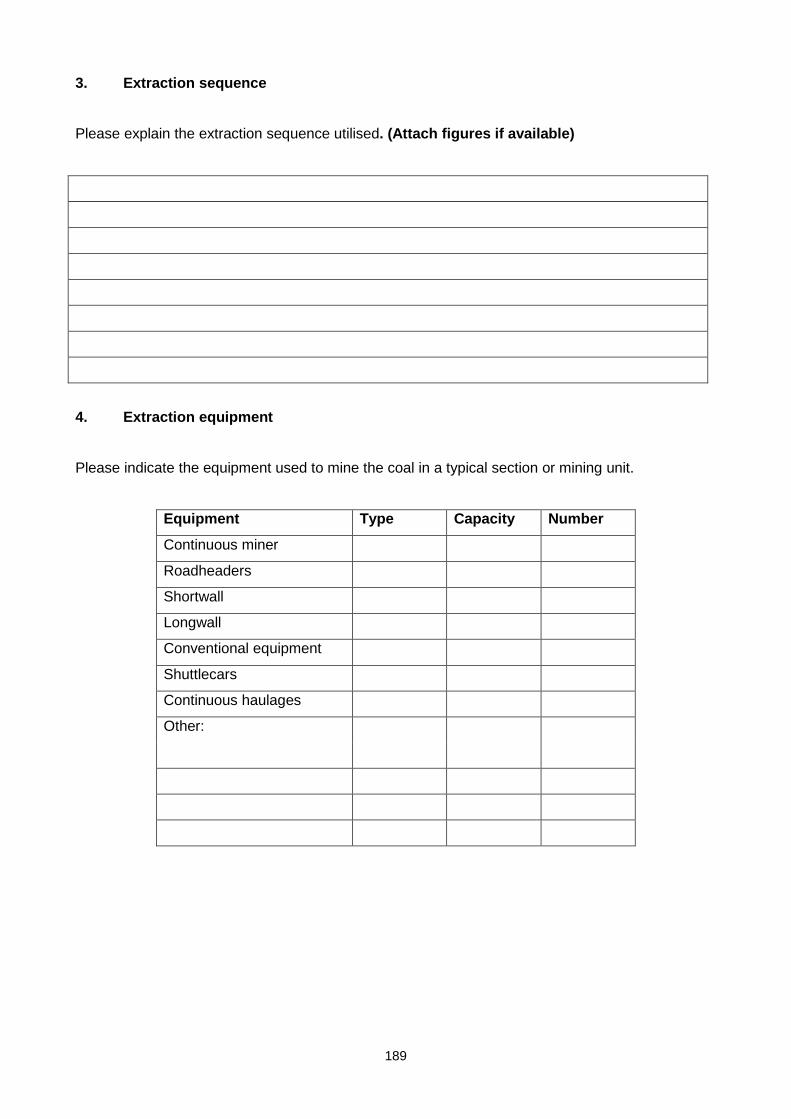
189
3. Extraction sequence
Please explain the extraction sequence utilised. (Attach figures if available)
4. Extraction equipment
Please indicate the equipment used to mine the coal in a typical section or mining unit.
Equipment Type Capacity Number
Continuous miner
Roadheaders
Shortwall
Longwall
Conventional equipment
Shuttlecars
Continuous haulages
Other:

190
5.1 Production rates
Output / Shift / Month Av. (3 months)
Development panels
Pillar extraction panels
Other

191
5.2 Personnel employed
Number of employees Number Can you supply a
detailed breakdown
Yes No
Development panels
Pillar extraction panels
Other
6. Original design parameters
Pillar size extracted:
Width
Height
Bord width
Seam thickness
Depth to floor
Parting distance to higher Seams
Parting distance to lower Seams
Thickness of adjacent Seams
Were adjacent Seams previously mined, if so, what pillar sizes,
bord widths and pillar heights were used?
Yes No
Were pillars superimposed
Pillar designed safety factor per section
Are barrier pillars used?
If so, what are their widths?

192
7. Current pillar conditions and measurements
Current dimensions (m)
Pillar width
Bord width
Total spalling (from the marks in the roof)
Mining height
Stone dusting
Time since dusting
If CM section, cutting marks on the sidewalls
Sill thickness
Distance to sill
Immediate roof? And thickness
Immediate floor? And thickness
Number of roads to calculate panel width
7.1 Roof and support conditions
Roof competence
If there is any roof fall: density and height?
Support type
Support efficiency
Support pattern
Installation of support
If there is failure in support, type of failure?
Support length
Current support conditions
7.2 Additional information
Discontinuities in the roof and pillars
Pillar punching
Any weakness in pillar (soft layers)
Roof pillar contact
Pillar fracturing
Top/bottom coaling
Presence of slips and/or faults
Presence of stone or shale layers

193
7.3 Problems experienced with pillar extraction + solutions if possible
8. Age of pillars
Average age of pillar (per section)
Age of panel being extracted
9. Quality
YES NO
9.1 Were there noticeable changes to coal quality from pillar extraction
panels compared to development sections?
If yes, what were the changes?
What were the variations in yield?
9.2 Were there noticeable changes to coal size grading from pillar
extraction panels compared to development sections?
If yes, what was the change in coal grading size?
Did this effect revenue?

194
10 Surface
YES NO
Was surface disturbance caused by pillar extraction panels?
If yes:
Extent of subsidence
If yes:
Magnitude of subsidence
Did pillar extraction affect the water table?
Did pillar extraction affect upper or lower Seam mining, if there is one?
11. Underground
YES NO
Did pillar extraction result in any problems with spontaneous combustion?
If yes, can you provide records or evidence?
Did pillar extraction result in any problems with methane accumulations in or
around the goaf line?
If yes, can you provide records or evidence?
Did pillar extraction result in any problems with airflow?
If yes, can you provide records or evidence?
Did pillar extraction result in any problems with geotechnology or geology
If yes, can you provide records or evidence?
Pillar/Panel behaviour
Roof – support, secondary support, collapses
Sidewalls – spalling, prior/during extraction – extent of
Pillar behaviour during extraction:
Eg. Stable, crushing, failing
Did pillar extraction affect adjacent panels?
If yes, please specify the effects.

195
12. Costs/Revenue
What was or is the operating cost of pillar extraction
What was or is the operating cost for development panels?
What aspects of the operations resulted in the major differences?
Was revenue influenced by pillar extraction operations? If so, what was the influencing factor?
13. Engineering
Did pillar extraction operations result in changes to equipment availability? If so, to what extent?
Were equipment modifications necessary? If so, please briefly indicate modifications
Can you provide detail of cases of damage / collapses on equipment and costs thereof
14. Safety and Health
To what extent did pillar extraction operations influence the safety record of the mine?
Can you provide safety records as support evidence? YES NO

196
15. General
YES NO
Do mine standards for pillar extractions exist
Can section plans of areas visited or where pillar extraction has been done
be made available?
Can documentation pertaining to pillar extraction, e.g. productivity and
technical reports, where collapses have occurred be made available?

197
Appendix 5: Tables A1 to A7
Table A51: Assignment of probabilities for local stability
LOCAL STABILITY
PILLAR
INSTABILITY
ROOF INSTABILITY FLOOR INSTABILITY
Pillar age Probability Age of workings Risk level Probability
Age of workings Probability
Less than 3 years Extremely low 1.00E-06 Less than 3 years Extremely low 1.00E-06 Less than 3 years Extremely low 1.00E-06 3 to 10 years Low 1.00E-04 3 to 10 years Very low 1.00E-05 3 to 10 years Very low 1.00E-05 10 to 20 years Moderate 1.00E-03 10 to 20 years Low 1.00E-04 10 to 20 years Low 1.00E-04 More than 20 years High 1.00E-02 More than 20 years Moderate 1.00E-03 More than 20 years Moderate 1.00E-03
Pillar scaling Roof conditions Floor composition None Extremely low 1.00E-06 V Good Extremely low 1.00E-06 Sandstone > 1m Extremely low 1.00E-06 Minor Low 1.00E-04 Minor failures Low 1.00E-04 Laminated SST&Shale Very low 1.00E-05 Moderate Moderate 1.00E-03 Some collapsed Moderate 1.00E-03 Shale/mudstone Low 1.00E-04 Severe Very high 1.00E-01 Severe collapses Very high 1.00E-01
Pillar discontinuities
1.48.1.1.1 Discontinuities in roof
Presence of water
None Extremely low 1.00E-06 None Extremely low 1.00E-06 None Extremely low 1.00E-06 Minor cleats Low 1.00E-04 Minor joints Low 1.00E-04 Damp Low 1.00E-04 Cleats and joints Moderate 1.00E-03 Slips and joints Moderate 1.00E-03 Wet Moderate 1.00E-03 Frequent major slips High 1.00E-02 Frequent major slips High 1.00E-02 Flooded High 1.00E-02
Factor of safety Roof composition Floor undulations Greater than 2.0 Extremely low 1.00E-06 Sandstone > 1m Extremely low 1.00E-06 None Extremely low 1.00E-06 1.6 to 2.0 Low 1.00E-04 Laminated
SST&Shale Low 1.00E-04 Minor Very low 1.00E-05
1.3 to 1.6 High 1.00E-02 Shale/mudstone Moderate 1.00E-03 Occasional rolls Low 1.00E-04 Less than 1.3 Very high 1.00E-01 Friable/Claystone High 1.00E-02 Major rolls Moderate 1.00E-03
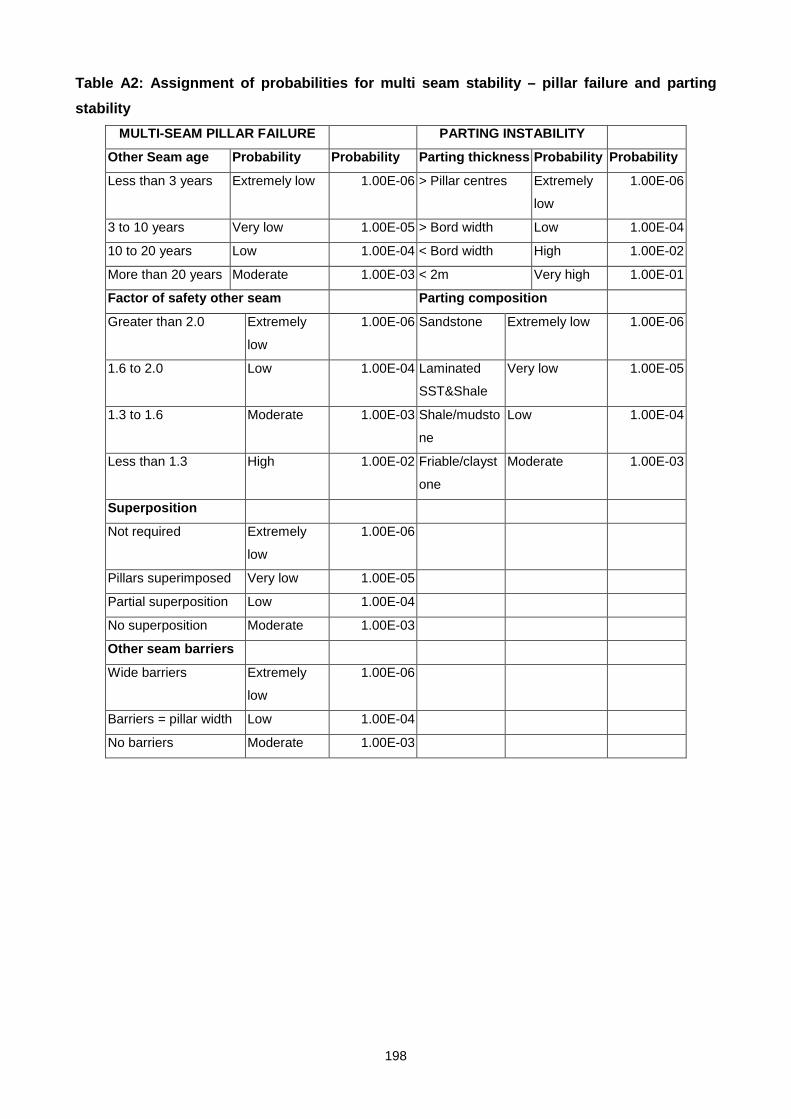
198
Table A2: Assignment of probabilities for multi seam stability – pillar failure and parting
stability
MULTI-SEAM PILLAR FAILURE PARTING INSTABILITY
Other Seam age Probability Probability Parting thickness Probability Probability
Less than 3 years Extremely low 1.00E-06 > Pillar centres Extremely
low
1.00E-06
3 to 10 years Very low 1.00E-05 > Bord width Low 1.00E-04
10 to 20 years Low 1.00E-04 < Bord width High 1.00E-02
More than 20 years Moderate 1.00E-03 < 2m Very high 1.00E-01
Factor of safety other seam Parting composition
Greater than 2.0 Extremely
low
1.00E-06 Sandstone Extremely low 1.00E-06
1.6 to 2.0 Low 1.00E-04 Laminated
SST&Shale
Very low 1.00E-05
1.3 to 1.6 Moderate 1.00E-03 Shale/mudsto
ne
Low 1.00E-04
Less than 1.3 High 1.00E-02 Friable/clayst
one
Moderate 1.00E-03
Superposition
Not required Extremely
low
1.00E-06
Pillars superimposed Very low 1.00E-05
Partial superposition Low 1.00E-04
No superposition Moderate 1.00E-03
Other seam barriers
Wide barriers Extremely
low
1.00E-06
Barriers = pillar width Low 1.00E-04
No barriers Moderate 1.00E-03

199
Table A3: Assignment of probabilities for multi seam stability – mining above/below
previous goaf
MULTI-SEAM MINING BELOW GOAF MULTI-SEAM MINING ABOVE GOAF
Seam separation Probability Probability Seam separartion Probability Probability
> Pillar centers Extremely low 1.00E-06 > Pillar centres Low 1.00E-04
> Bord width Low 1.00E-04 > Bord width Moderate 1.00E-03
< Bord width Moderate 1.00E-03 < Bord width High 1.00E-02
< 2m High 1.00E-02 < 2m Very high 0.1
Goaf consolidation Goaf consolidation
Goaf age > 5 years Extremely low 1.00E-06 Goaf age > 5 years Extremely
low
1.00E-06
Goaf age 2 to 5 years Low 1.00E-04 Goaf age 2 to 5 years Low 1.00E-04
Goaf age < 2 years Moderate 1.00E-03 Goaf age < 2 years Moderate 1.00E-03
Remnant pillars Remnant pillars
None Extremely low 1.00E-06 None Extremely
low
1.00E-06
Small snooks Low 1.00E-04 Small snooks Low 1.00E-04
Partial pillars Moderate 1.00E-03 Partial pillars Moderate 1.00E-03
Full pillars High 1.00E-02 Full pillars High 1.00E-02
Hydrological hazard
Dry Extremely low 1.00E-06
Small inflow expected Low 1.00E-04
Water accumulations Moderate 1.00E-03
Flooded High 1.00E-02

200
Table A4: Assignment of probabilities for regional stability – caving and subsidence
hazards
CAVING HAZARD SUBSIDENCE HAZARD
Dolerite sills Probability Probability Subsidence mode Probability Probability
No dolerite Extremely
low
1.00E-06 No subsidence
expected
Extremely
low
1.00E-06
Dolerite < 20 m Low 1.00E-04 Depth > 100 x height Low 1.00E-04
Dolerite 20 - 40 m Moderate 1.00E-03 Depth 10 to 100 x
height
Moderate 1.00E-03
Dolerite > 40m High 1.00E-02 Depth < 10x height High 1.00E-02
Sandstone beams Surface usage
No sandstone Extremely
low
1.00E-06 Unimproved Extremely
low
1.00E-06
10 - 20m sandstone Low 1.00E-04 Agriculture Low 1.00E-04
20 - 40m sandstone Moderate 1.00E-03 Infrastructure Moderate 1.00E-03
Dwellings High 1.00E-02
Panel span/depth ratio Hydrology
Span > 3xdepth Extremely
low
1.00E-06 No groundwater Extremely
low
1.00E-06
Span 2 to 3 x depth Low 1.00E-04 Surface runoff Low 1.00E-04
Span 1 to 2 x depth Moderate 1.00E-03 Streams Moderate 1.00E-03
Span < depth High 1.00E-02 Water accumulations High 1.00E-02

201
Table A5: Assignment of probabilities regional stability – regional geology and stress
hazards
REGIONAL GEOLOGY HAZARD STRESS HAZARD
Major lineaments Probability Probability Horizontal stress Probability Probability
No lineaments Low 1.00E-04 No known
problems
Extremely
low
1.00E-06
Lineament through Moderate 1.00E-03 Minor spalling Low 1.00E-04
Cutter roof Moderate 1.00E-03
Roof failures
expected
High 1.00E-02
Faults Adjacent mining
None Extremely
low
1.00E-06 No adjacent mining Extremely
low
1.00E-06
Minor faults <1m Low 1.00E-04 Pillars adjacent Low 1.00E-04
Moderate faults 1-3m Moderate 1.00E-03 Stooping on one
side
Moderate 1.00E-03
Major faults > 3m High 1.00E-02 Stooping two/more
sides
High 1.00E-02
Intrusions
None Extremely
low
1.00E-06
Minor dykes <1m Low 1.00E-04
Moderate dykes 1-3m Moderate 1.00E-03
Major dykes > 3m High 1.00E-02

202
Table A6: Example of risk rating – Single-seam pillar recovery
Pillar Recovery - Stability Risk Assessment
Mine: Single seam example
Panel: Test panel 1 Seam: 2A Date: 12/9/00
Risk rating 70
Risk level Risky
Total probability of failure 1.52%
Risk factor Assessment Probability Description
PILLAR INSTABILITY 0.011 High probability
Pillar age 10 to 20 years 0.001
Pillar scaling Minor 1.00E-04
Pillar discontinuities Minor cleats 1E-04
Factor of safety 1.3 to 1.6 0.01
ROOF INSTABILITY 0.000301 Low probability
Age of workings 10 to 20 years 1E-04
Roof conditions Minor failures 1.00E-04
Discontinuities in roof Minor joints 1E-04
Roof composition Sandstone > 1m 1E-06
FLOOR INSTABILITY 0.0011109 Moderate
probability
Age of workings 10 to 20 years 1E-04
Floor composition Laminated
SST&Shale
1E-05
Presence of water Wet 0.001
Floor undulations None 1E-06
MULTI-SEAM
INSTABILITY
0.00000 No risk
MULTI-SEAM MINING
ABOVE GOAF
0 No risk
Seam separartion 0
Goaf consolidation 0
Remnant pillars 0
MULTI-SEAM MINING
BELOW GOAF
0 No risk
Seam separation 0
Goaf consolidation 0
Remnant pillars 0
Hydrological hazard 0

203
MULTI-SEAM PILLAR
FAILURE
0 No risk
Other seam age 0
Factor of safety other seam 0
Superposition 0
Other seam barriers 0
PARTING INSTABILITY 0 No risk
Parting thickness 0
Parting composition 0
CAVING HAZARD 0.0011009 Moderate
probability
Dolerite sills No dolerite 1E-06
Sandstone beams 10 - 20m sandstone 1E-04
Panel span/depth ratio Span 1 to 2 x depth 0.001
SUBSIDENCE HAZARD 0.0011998 Moderate
probability
Subsidence mode Depth 10 to 100 x
height
0.001
Surface usage Agriculture 1E-04
Hydrology Surface runoff 1E-04
REGIONAL GEOLOGY
HAZARD
0.000201 Low probability
Major lineaments No lineaments 1E-04
Faults Minor faults <1m 1E-04
Intrusions None 1E-06
STRESS HAZARD 0.0002 Low probability
Horizontal stress Minor spalling 1E-04
Adjacent mining Pillars adjacent 1E-04

204
Table A7: Example of risk rating – Multi-seam pillar recovery
Pillar Recovery - Stability Risk Assessment
Mine: Multi-seam example
Panel: Test panel 2 Seam: 2A Date: 12/9/00
Risk rating 74
Risk level Risky
Total probability of failure 2.65%
Risk factor Assessment Probability Description
PILLAR INSTABILITY 0.011 High probability
Pillar age 10 to 20 years 0.001
Pillar scaling Minor 1.00E-04
Pillar discontinuities Minor cleats 1E-04
Factor of safety 1.3 to 1.6 0.01
ROOF INSTABILITY 0.000301 Low probability
Age of workings 10 to 20 years 1E-04
Roof conditions Minor failures 1.00E-04
Discontinuities in roof Minor joints 1E-04
Roof composition Sandstone > 1m 1E-06
FLOOR INSTABILITY 0.0011109 Moderate
probability
Age of workings 10 to 20 years 1E-04
Floor composition Laminated SST&Shale 1E-05
Presence of water Wet 0.001
Floor undulations None 1E-06
MULTI-SEAM INSTABILITY 0.01139 High probability
MULTI-SEAM MINING
ABOVE GOAF
0 No risk
Seam separartion 0
Goaf consolidation 0
Remnant pillars 0
MULTI-SEAM MINING
BELOW GOAF
0 No risk
Seam separation 0
Goaf consolidation 0
Remnant pillars 0
Hydrological hazard 0
MULTI-SEAM PILLAR
FAILURE
0.0111878 High probability
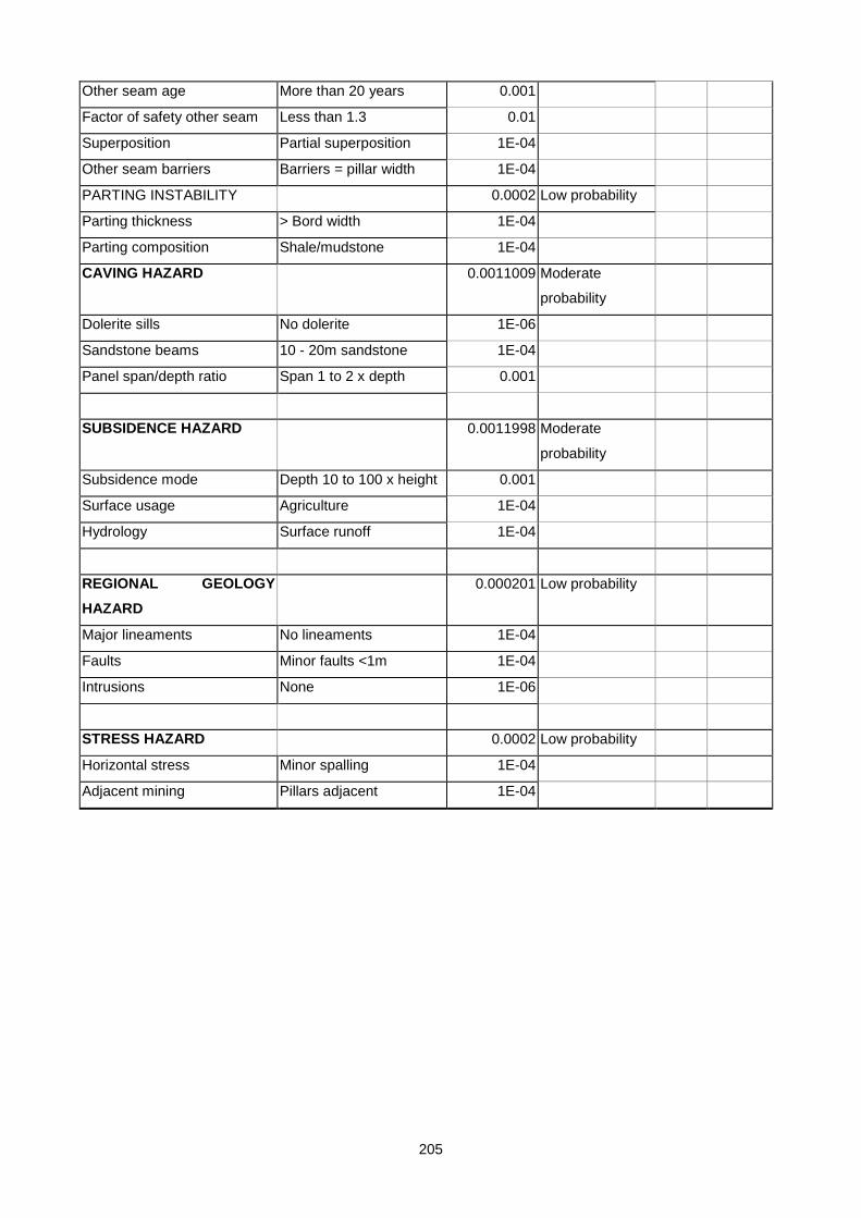
205
Other seam age More than 20 years 0.001
Factor of safety other seam Less than 1.3 0.01
Superposition Partial superposition 1E-04
Other seam barriers Barriers = pillar width 1E-04
PARTING INSTABILITY 0.0002 Low probability
Parting thickness > Bord width 1E-04
Parting composition Shale/mudstone 1E-04
CAVING HAZARD 0.0011009 Moderate
probability
Dolerite sills No dolerite 1E-06
Sandstone beams 10 - 20m sandstone 1E-04
Panel span/depth ratio Span 1 to 2 x depth 0.001
SUBSIDENCE HAZARD 0.0011998 Moderate
probability
Subsidence mode Depth 10 to 100 x height 0.001
Surface usage Agriculture 1E-04
Hydrology Surface runoff 1E-04
REGIONAL GEOLOGY
HAZARD
0.000201 Low probability
Major lineaments No lineaments 1E-04
Faults Minor faults <1m 1E-04
Intrusions None 1E-06
STRESS HAZARD 0.0002 Low probability
Horizontal stress Minor spalling 1E-04
Adjacent mining Pillars adjacent 1E-04
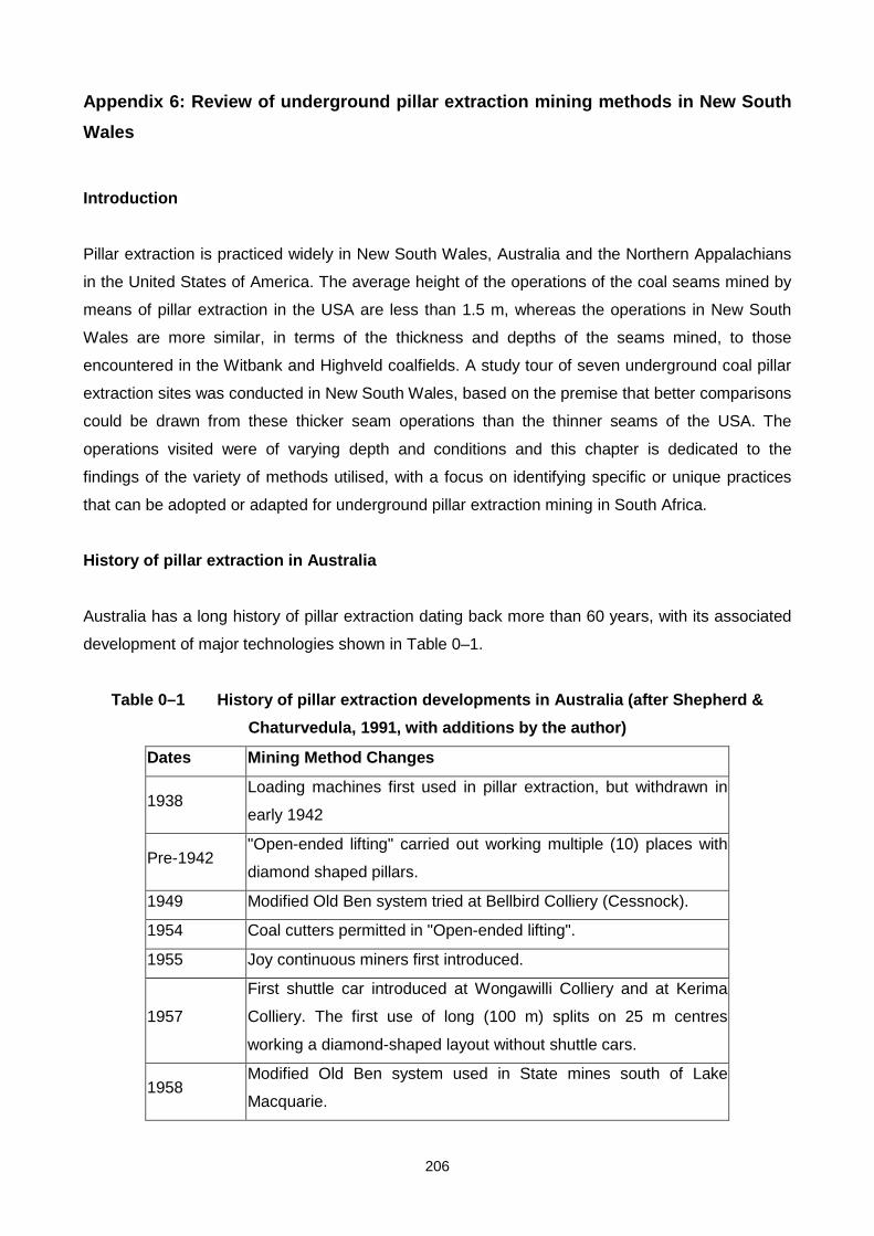
206
Appendix 6: Review of underground pillar extraction mining methods in New South
Wales
Introduction
Pillar extraction is practiced widely in New South Wales, Australia and the Northern Appalachians
in the United States of America. The average height of the operations of the coal seams mined by
means of pillar extraction in the USA are less than 1.5 m, whereas the operations in New South
Wales are more similar, in terms of the thickness and depths of the seams mined, to those
encountered in the Witbank and Highveld coalfields. A study tour of seven underground coal pillar
extraction sites was conducted in New South Wales, based on the premise that better comparisons
could be drawn from these thicker seam operations than the thinner seams of the USA. The
operations visited were of varying depth and conditions and this chapter is dedicated to the
findings of the variety of methods utilised, with a focus on identifying specific or unique practices
that can be adopted or adapted for underground pillar extraction mining in South Africa.
History of pillar extraction in Australia
Australia has a long history of pillar extraction dating back more than 60 years, with its associated
development of major technologies shown in Table 0–1.
Table 0–1 History of pillar extraction developments in Australia (after Shepherd &
Chaturvedula, 1991, with additions by the author)
Dates Mining Method Changes
1938 Loading machines first used in pillar extraction, but withdrawn in
early 1942
Pre-1942 "Open-ended lifting" carried out working multiple (10) places with
diamond shaped pillars.
1949 Modified Old Ben system tried at Bellbird Colliery (Cessnock).
1954 Coal cutters permitted in "Open-ended lifting".
1955 Joy continuous miners first introduced.
1957
First shuttle car introduced at Wongawilli Colliery and at Kerima
Colliery. The first use of long (100 m) splits on 25 m centres
working a diamond-shaped layout without shuttle cars.
1958 Modified Old Ben system used in State mines south of Lake
Macquarie.

207
1957-1961
Initial attempts at Wongawilli and Nebo Collieries to work a long
fender system (precursor to the Wongawilli system) and "split and
lift" with continuous miners and shuttle cars were unsatisfactory.
1961 First successful Wongawilli system panels worked at Wongawilli
and Nebo Collieries.
Post-1961 Continued improvement of the Wongawilli system especially with
regard to split centre dimensions.
Late-1980's Modified Wongawilli systems developed by driving splits on each
side of the panel headings and lifting left and right from the splits.
Mid-1990’s Successful use of pillar stripping at Endeavour and Cooranbong
Collieries for partial extraction.
Early- 2000’s
Successful application of pillar stripping at Clarence, Munmorah &
Cooranbong Collieries for partial extraction and at United Colliery
for full and partial extraction.
Current pillar extraction operations in new South Wales
This section presents the observations of the full and partial pillar extraction operations visited in
New South Wales. Information was obtained from five full pillar extraction operations and three
partial pillar extraction operations.
Full pillar extraction operations
There were five full pillar extraction operations in New South Wales at the time of the visit. Four of
these were visited, while information on recent experience with full pillar extraction was obtained
from the fifth operation. The observations made at each of these operations are detailed here
including, but not limited to, factors such as mining method, mining equipment and unique features
of the operation.
Bellambi West
The Bellambi West Mine is the only pillar extraction operation of the Southern Coalfield in New
South Wales. It is situated on the Picton Road to the west of Wollongong (Figure 0–1). The high
grade Bulli Seam is mined which yields a hard coking coal with a low ash, low to medium volatile
matter content, low sulphur and high rank which is suitable for both the domestic and export
market. The coal produced from this colliery is all exported through the Port Kembla loading facility
at Wollongong.

208
Figure 0–1 Location of Bellambi West Colliery
The mine does not usually practice pillar extraction as its major production source comes from
longwalling. The previous owners sold off the mine citing floor heave and poor roof conditions for
their future planned longwall panels as the reason for the sale. The new owners identified these
roof and floor problems as being limited in extent and began developing for new longwall panels in
the same area where these poor conditions were previously encountered. No further problems
associated with roof or floor have to date been encountered. To sustain cashflow and demand for
their product while longwall development was taking place, it was decided to extract a series of
chain pillars in two separate areas of the mine. These panels served as travelling ways for the
previously mined longwall panels and were thus not specifically designed to be extracted. The
panel layouts thus were generally irregular and were also situated between two goaves. A modified

209
Wongawilli split and lift method of double-sided extraction with Articulated Breaker Line Supports
(ABLS’s) was used in both sections, as the chain pillars were of significant size and strength to
support this mining method. The extraction panels had barrier pillars 32 m wide separating them on
either side from the goaves. Both panels were extracted in a manner as depicted in Figure 0–2.
Figure 0–2 Pillar extraction sequence at Bellambi West Colliery
The typical lifting operation is shown in Figure 0–2 with approved variations also used. Snooks
were left as shown in Figure 0–3, although these were sometimes split to encourage goafing to
closely follow the extraction line.

210
Figure 0–3 Split and lift pillar extraction operation at Bellambi West Colliery
The splits were driven (as shown in Figure 0–2) to a maximum of 15 m before being supported with
a Fletcher roofbolter which places four 1.5 m point anchor pre-tensioned bolts with straps per row,
with the rows spaced a distance of 1.2 m apart. The bord widths in all instances were an average
of 5.5 m. Once bolted, the split was holed and supported before lifting back of the newly created 12
m wide pillars took place. The panels were operated with remote controlled continuous miners (a
Joy 12CM11) with two Joy 15SC shuttle cars, each with an approximate 15 tonne capacity. Three
Eimco Articulated Breaker Line Supports (ABLS’s) operated by remote control were employed.
Each of the ABLS’s provided a maximum support load of 480 tonnes and were positioned as
shown in Figure 0–3, with the middle ABLS required to follow the centre line of the roadway. The
ABLS’s, however, were not set to their maximum load as this may have resulted in the premature
fracturing of the roof. Generally they were set to approximately one third of their maximum load,
which equated to approximately 160 tonnes. The ABLS’s were moved forward a maximum of 2 m
each at any one time and only one at a time. They were set to the roof after each move forward
before being moved again. They were spaced a maximum of 2 m from each other and kept as
close to the continuous miner and solid fender as possible (as shown in Figure 0–3). In addition to
the ABLS’s, timber breaker lines were also used as ancillary support.
The average production form these two extraction panels was approximately 60,000 tonnes per
month whereas the longwall development panel produced an average of 35,000 tonnes per month.
There were eight personnel (detailed in Table 0–2) operating per shift in the extraction panels
operating on a three shift per day basis, five days per week. This was two persons less than the
longwall development panel where there were two dedicated roofbolt operators.
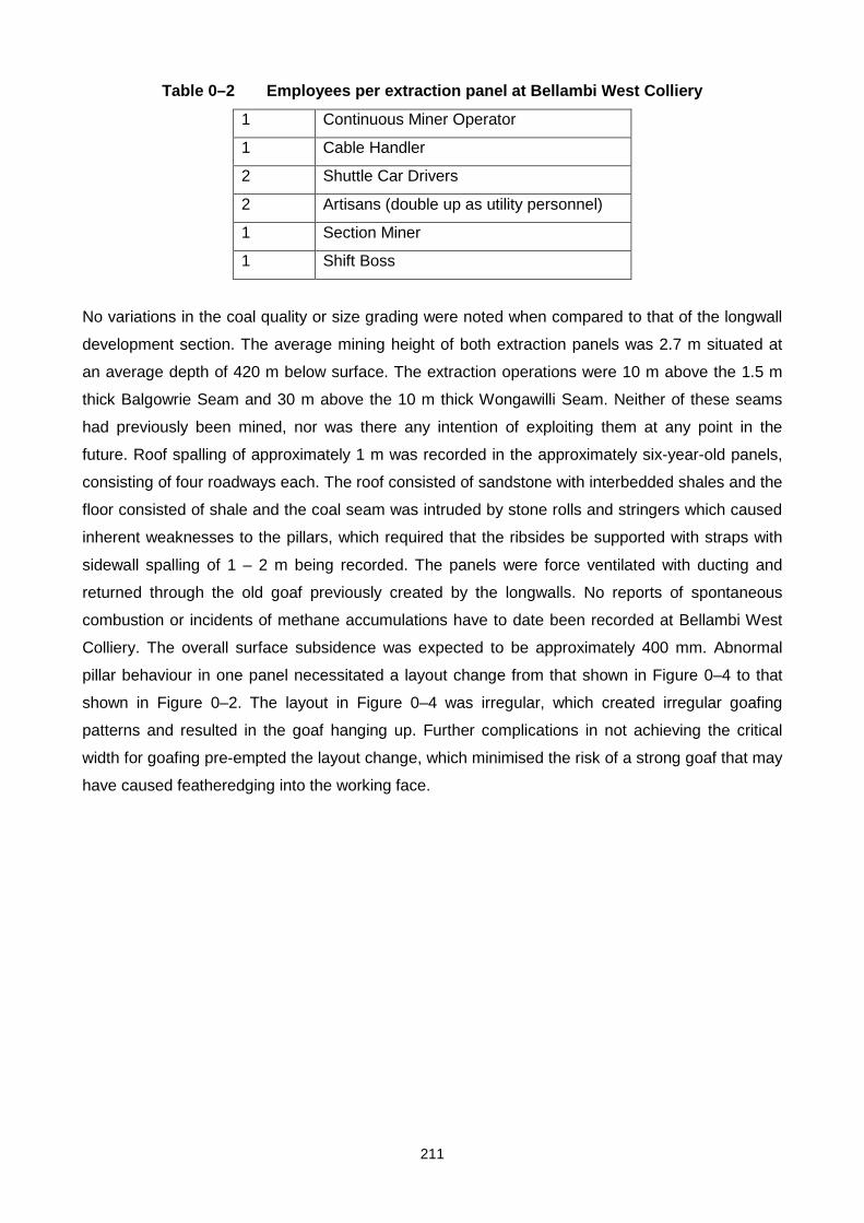
211
Table 0–2 Employees per extraction panel at Bellambi West Colliery
1 Continuous Miner Operator
1 Cable Handler
2 Shuttle Car Drivers
2 Artisans (double up as utility personnel)
1 Section Miner
1 Shift Boss
No variations in the coal quality or size grading were noted when compared to that of the longwall
development section. The average mining height of both extraction panels was 2.7 m situated at
an average depth of 420 m below surface. The extraction operations were 10 m above the 1.5 m
thick Balgowrie Seam and 30 m above the 10 m thick Wongawilli Seam. Neither of these seams
had previously been mined, nor was there any intention of exploiting them at any point in the
future. Roof spalling of approximately 1 m was recorded in the approximately six-year-old panels,
consisting of four roadways each. The roof consisted of sandstone with interbedded shales and the
floor consisted of shale and the coal seam was intruded by stone rolls and stringers which caused
inherent weaknesses to the pillars, which required that the ribsides be supported with straps with
sidewall spalling of 1 – 2 m being recorded. The panels were force ventilated with ducting and
returned through the old goaf previously created by the longwalls. No reports of spontaneous
combustion or incidents of methane accumulations have to date been recorded at Bellambi West
Colliery. The overall surface subsidence was expected to be approximately 400 mm. Abnormal
pillar behaviour in one panel necessitated a layout change from that shown in Figure 0–4 to that
shown in Figure 0–2. The layout in Figure 0–4 was irregular, which created irregular goafing
patterns and resulted in the goaf hanging up. Further complications in not achieving the critical
width for goafing pre-empted the layout change, which minimised the risk of a strong goaf that may
have caused featheredging into the working face.

212
Figure 0–4 Original pillar extraction sequence at Bellambi West Colliery
One fatality has occurred while conducting this pillar extraction operation. No details as to the
exact nature of the fatality were available, except that it was associated with a roof fall while
attempting to reset the continuous miner that had tripped under unsupported roof. A code of
practice together with specialised training of the personnel was conducted before the extraction
started. No information pertaining to the costs of the operation could be made available as a result
of confidentiality of the information.
Charbon Colliery

213
Charbon Colliery is located in the Western Coalfield near the town of Kandos, some 250 km
northwest of Sydney (see Figure 0–5).
Figure 0–5 Location of Charbon, Ivanhoe and Clarence Collieries
The Lithgow seam is mined which has a medium to high volatile matter, medium to high ash and
low sulphur. All production from Charbon Colliery is exported via rail to the Port Kembla loading
facility at Wollongong. The Lithgow seam is generally 2.7 m thick with local variations of the
thickness by a few centimetres caused by an overseam dirt band. It is the only seam mined, and is
situated 4.5 m below the Lidsdale seam that has a thickness of 100 mm. The overlying strata
consist of bands of claystone, mudstone and sandstone (which are considered to be weak) and the
floor consists of shales and tuff (which are generally considered strong). The depth of cover to the
Lithgow seam varies from 190 m at the centre of the mining lease to 30 m at the extreme inbye
end of the panel and outcrops on the perimeter of the mountain that overlies the deposit. Two clay
bands exist within the coal seam, which expand when wet. These bands do not effect the mining
operation however.
A modified Wongawilli split and lift full pillar extraction method is used which is limited to the 30 m
cover line to prevent damage to the mountainside. Beyond the 30 m cover line only partial
214
extraction without caving can occur by means of the creation of small pillars (between 16 m and 20
m square) by usual bord and pillar mining techniques. Generally, for the full extraction panels, a
panel is developed out some 650 m with three headings at 40 m centres with crosscuts (splits)
being driven at 50 m centres to create 3-way and 4-way intersections. This initial development,
once complete, leaves the final extraction panel usually consisting of 14 splits. A barrier pillar of 40
m width is left between extraction panels. From the 6th crosscut onward, a 25 m split between the
headings on the solid side of the panel is done (i.e. the headings farthest from the previous goaf) to
facilitate better ventilation and shuttle car wheeling arrangements. In addition to these splits, “run-
outs” are driven from the heading closest to the goaf side from every third crosscuts to hole
through into the previous goaf to facilitate control against any inrushes of water and/or gas into the
workings from the previous goaf. The primary purpose of the 3 heading development system used
at Charbon Colliery is to reduce the number of 4-way intersections formed during the development
phase. Previous extraction panels had experienced roof problems associated with the 4-way
intersections, which had to be supported using expensive cable trusses.
The 5.5 m wide roadways are formed by either a Joy 12CM12 or Joy 12CM11 (both remote
controlled) and are supported with four 2.1 m full column resin supported roofbolts installed per row
with a strap, spaced 1.8 m between the rows. The roofbolting operation is done using an on board
bolting system. Two 15 tonne capacity Joy 15SC shuttle cars are used to produce approximately
14,000 tonnes per month on development.
The pillar extraction process is shown in Figure 0–6. Upon completion of the development as
described previously, the extraction process begins with the pillar furthest inbye on the goaf side
being split and supported along its 25 m centre to create pillars that are nominally 20 m wide.
These splits are supported with four 1.8 m full column resin supported roofbolts installed per row
with a strap, with the rows spaced 1.8 m apart. The roofbolting operation is again conducted using
an on board bolting system. The use of shorter roofbolts (as opposed to those used during
development) is based on the premise that the roadway will only stand for a short duration prior to
extraction. Three remote controlled Voest Alpine ABLS’s are then used in this left and right lifting of
the fenders in the manner shown in Figure 6. The ABLS’s are advanced one at a time to a
maximum of 2 m at any one time before being set to the roof and are spaced a maximum of 2 m
apart. The middle ABLS is required to follow the centre line of the roadway.

215
Figure 0–6 Modified Wongawilli split and lift operation at Charbon Colliery
In addition to the use of ABLS’s, timber breaker props consisting of two rows of 5 props each are
set in each of the headings, with only one row being set in the heading furthest from the goaf. In
this way extraction takes place in a straight line extending from the previous goaf line. The roof
bolting rigs are removed from the continuous miner prior to lifting. The maximum lift taken is
approximately 9 m into the previous goaf side and approximately 10.5 m into the solid side. Thus
only half the pillar is extracted per lift into the solid side, although the lifts into the goaf side will hole
into the previous goaf. The angle of lifting is between 60° and 70° and the lifts are cut the width of
the continuous miner cutter head (approximately 3.6 m). The ABLS’s are moved as shown in
Figure 0–6 and are set to the roof with a pressure of one third its maximum loading capacity
(known locally as the edge of the “green zone”). When they start to take load, the gauge moves
into the “yellow zone”, indicating that the roof is settling. At this point the ABLS’s are moved
forward and thus closer to the solid fenders to limit the span across which the goaf could
featheredge and in so doing also provides greater protection for the continuous miner driver.
Snooks are left as shown in Figure 0–7, with the snooks closest to the solid side of the panel being
10 m wide to ensure that a roadway remains open for return ventilation of the panel. This
extraction process continues across the intersection toward the solid side of the panel and once
completed the sequence starts again with the driving of a split through the pillar closest to the goaf
side and lifting back toward the solid across the intersection toward the solid side of the panel. The
lifting operation on a per shift basis produces more than the development operation, as less
roofbolting is required by this operation.

216
Figure 0–7 Leaving of snooks during extraction operation at Charbon Colliery
The breakdown of personnel at Charbon Colliery is shown in Table 0–3.
Table 0–3 Employees per extraction panel at Charbon Colliery
5 Machine Operators
2 Artisans
1 Section Miner
In general, no adverse effects were reported with this operation. Thirteen panels to date have been
extracted using this method of mining. Rib spalling was noted during the lifting off operation that
was associated with a weight transfer from the previous goaf to the solid pillars outbye of the goaf.
Surface subsidence was noted, although this could not be accurately recorded due to the nature of
the mountainous surface. Some CO2 emissions were recorded which were associated with the
overlying Lidsdale seam being broken during goafing. Little effect of windblasts has been reported,
although precaution is taken when an extended goaf has not taken place.
The continuous miner has been buried on two previous occasions with no loss of life or injury. An
electrical breakdown in the last lift was the cause of one of the burials when the snook was unable
to provide adequate support for the roof cantilever, and the other was attributed to a geological
anomaly and the presence of an aquifer in the immediate roof of the panel being worked. The
ABLS’s were buried on one occasion, attributed to the hanging of the goaf for a prolonged period
of 5 weeks causing a violent goaf to overrun them.
No indication of the operating costs of the operation were made available due to confidentiality of
the information, but it was inferred that it was one of the lowest cost operating mines in the region

217
as a result of the long distance which has to be covered to transport the product to export facility at
Wollongong.
An interesting observation at this colliery was the use of a monorail system to suspend the
continuous miner’s power cable and water hose from the roof. This system reduces the hazard of
the cables being damaged by rib spall and also reduces the risk of back injury to the personnel. It
was reported that the loss of production from damage to the cables had been significantly reduced
since the inception of the monorail system.
Ivanhoe Colliery
Ivanhoe Colliery is a 200,000 tonne per year producer situated in the Western Coalfield near the
town of Lithgow, some 150 km west of Sydney (Figure 0–5). All of the coal produced from this
colliery is consumed by a nearby power station. It is a full pillar extraction operation, mining the
Lithgow and Lidsdale seams that are separated by a 15 – 20 cm thick clay intrusion. The operation
lies 10 m below the Irondale seam, which is unmined. This 10 m separation consists of sandstone
and mudstone layers. Two sections operate on a single shift basis, one of which is the pillar
extraction panel, and the other a preparation panel for future pillar extraction. Both sections
operate with a section miner and five machine operators with a total of 20 people employed.
The mine has been in operation since the early part of the 20th century when large areas were
developed by the bord and pillar method of mining approximately 60 m below surface. At the time
of this primary development, the bottom 1.5 m horizon of the 2.7 m thick coal seam was mined by
drill and blast methods, to create bord width approximately 5 m wide, with no support of the roof or
ribsides being conducted at that time. Some limited split and quarter extraction of these pillars
subsequently took place in some areas of the mine at various stages during the mines life. A
recent decision made by the current owners to fully extract certain areas of the mine has prolonged
the life of the mine by an estimated 3 years. The process of extraction is preceded by panel
rehabilitation, which takes the form of brushing top coal to the full seam height of previously
developed areas and installing two 1.8 m long resin roof bolts in a row, which are 2 m apart. A
remote controlled Joy 12CM11 continuous miner with two 15 tonne capacity Noyes Hydrocars
performs this rehabilitation function. The roofbolting is conducted with a custom designed
roofbolter. Production from the preparation panel is variable and low, as limited areas exist for
future pillar extraction. Also, the areas being prepared for pillar extraction have varying physical
conditions, with previous roof falls into the intersections being one of the largest problems,
rendering many areas inaccessible. CO2 is also a problem as a result of a lack of ventilation
through these old areas. Once rehabilitation is complete, the extraction of the pillars can
commence. The layout as shown in Figure 0–8 shows the current extraction panel at the colliery.

218
Figure 0–8 Pillar extraction sequence at Ivanhoe Colliery
Although the mine has approval for single and double sided lifting of the pillars, Ivanhoe utilises
only the single sided lifting process with a remote controlled Joy 12CM11 continuous miner, two 15
tonne Noyes Hydrocars and two remote controlled Voest Alpine Breaker Line Supports (ABLS’s). A
third ABLS would be used if double sided lifting were to be utilised. The ABLS’s are advanced a
maximum of 2 m at any one time and can only be moved one at a time. They are spaced a
maximum distance of 2 m apart to reduce the overall span of the roof. A method of extraction
similar to that shown in Figure 0–9is currently used.
Figure 0–9 Approved pillar extraction utilising ABLS’s at Ivanhoe Colliery
The pillars are extracted from right to left as shown in Figure 0–9 with the approximately 25 m long
by 10 m wide pillars lifted a maximum 9 m into the pillar, thus leaving a thin fender as protection for

219
the working face and as an indicator as to the status of the roof activity. It was noticed that the coal
was very friable and as a result was cut easily. The ABLS’s were set to only 25 percent of their
maximum loading capacity so as not to fracture the roof. The area being extracted was under
stress as evidenced by the row of pillars behind the extracted row spalling to such an extent that
the pillars were surrounded by rib spall reaching between one third and one half the height of the
pillar, with the extent of the spalling being approximately 0.5 m as noticed from marks on the roof.
This was probably a result of high abutment stresses from the irregular mining layout negatively
affecting the already aged pillars. An inference to cause of this spalling is the fact that the lower
part of the pillar slabbed approximately 30 cm as a result of time effects and having being formed
by drill and blast methods (Madden, 1987). This lower area would have created a situation
whereby the upper portion of the pillar slabbed as a result of having no support from the already
slabbed bottom portion of the pillar.
The area is overlain by State forest and, although subsidence has been noted, it is not a legal
requirement for subsidence to be measured. No indication as to the safety history or costs of the
operation could be made available, as this information was confidential.
United Colliery
United Colliery is situated in the Hunter Coalfield approximately 90 km west of Newcastle and 25
km south west of Singleton (Figure 0–1). The operation is just over 10 years old and produces
approximately 2.2 million tonnes of ROM coal from three production sections, all of which is
exported through the Newcastle ports to customers in Asia. Mining is undertaken in the Woodlands
Hill Seam, making United Colliery the deepest operation in the area at approximately 250 m below
surface at its current workings. The seam dips in a northwest to southeast direction from 40 m
below surface at the drift shaft complex to approximately 220 m at the current workings and it is
intersected normally to the dip direction by a number of fault planes. United Colliery is overlain by a
series of coal seams, the closest of which lies 170 m above the Woodlands Hill Seam. These
upper seams are mined using open cast methods and the caving activity associated with the
current pillar extraction panel at United Colliery does not affect these surface operations. The seam
height of the area varies from 3.2 m – 3.6 m with the mining height generally being 3.2 m. The
immediate roof consists of approximately 0.3 m of coal, which is overlain by a 3 m band of shales
and mudstones and then by a layer of competent sandstone, which is approximately 2.5 m thick.
The floor consists primarily of mudstone with some laminations. The lease area of the mine is
bounded by a number of dykes and severe fault zones that have dictated the length and layout of
the six extraction panels. A decision by the new owners in May 2001 to operate seven longwall
panels upon completion of the current and final 415 pillar extraction panel will leave the mine with
approximately seven years production.

220
Full extraction has taken place at the colliery since its inception although the latter panels are a
combination of full and partial extraction techniques. Panels of various sizes (as a result of the
geological boundaries) ranging from 5 – 9 road headings have been employed to varying degrees
of success. The initial extraction panels close to the drift shaft complex were shallower than the
later panels and these operated in generally better conditions than the later, deeper panels. In
these initial panels all the pillars were extracted, whereas the layouts and extraction sequences of
the later panels had to be changed to account for the effects of depth as well as the dip of the
seam that created unusual stress regimes on the left hand side of each of the panels. In these
instances the centre line of pillars were left standing to reduce the overall span of each panel.
Apart from leaving this centre line of pillars, the fenders were only partially extracted in some
areas, creating a situation of full and partial extraction techniques within the panel.
The current panel being extracted was driven using a 9 road heading layout (approximately 245 m
wide), creating pillars 40.5 m long by 30 m wide and utilising a remote controlled Joy 12CM12D
continuous miner and three 15 tonne capacity Joy 15SC shuttle cars. Halfway along the 2,500 m
long panel, the pillars were increased in size to 45 m long to 32.5 m wide to account for changing
stress conditions resulting from the increase in depth. The average bord width was 5.4 m. 30 m
wide barrier pillars separate the panels and these were not extracted as the panels were sealed
upon completion of the extraction process. The roof was supported systematically with a twin boom
Fletcher roofbolter installing rows of four 2.1 m long fully encapsulated roof bolts, with the rows
being 1.4 m apart. At intersections the support density increased to five 2.1 m bolts, with the rows
1.1 m spaced apart. Rib spall was a serious problem (particularly at the pillar edges), which
required support (with meshing in some areas). Further, the ventilation of the panel was split and
use was made of ventilation ducts to force the ventilation into the section. Upon completion of the
development, the pillars were extracted in a manner as shown in Figure 0–10.

221
Figure 0–10 Extraction layout at United Colliery
The pillars are lifted on a single and double-sided basis using two and three remote controlled
Jeffrey ABLS’s respectively (set to 200 tonnes) with timber props set as ancillary support. The
ABLS’s are limited to advance one at a time to a maximum of 2 m at any one time and set to the
roof. They are also set to a maximum distance of 2 m apart and the middle ABLS is required to
follow the centre line of the roadway when all three ABLS’s are used. The remote controlled
continuous miner is modified with the cutter head being reduced from 5.4 m wide on development
to 3.6 m wide on extraction. Three 15 tonne capacity shuttle cars are used during extraction. The
fenders are lifted at 60° and are cut to a maximum depth of 12 m to create a system of snooks and
small fenders as those shown in Figure 0–10. The pillars are a maximum age of two years at the
time of extraction, with the outbye pillars being the oldest.
This system of extraction yields approximately 1,350 tonnes per shift. There are 12 production
shifts per week on a three shift per day cycle. The remaining three shifts are used for maintenance
and panel work (e.g. belt retractions, rerouting of ventilation ducting, etc.). The two development
panels each produce approximately 1,250 tonnes per shift, working on the same shift basis as the
extraction panel. The extraction panel operates with one section miner and six machine operators
per shift, while the development panels each have one miner and eight machine operators (the
extra manpower being required for roofbolting). The colliery operates with a total labour
complement of 162.
The presence of methane increases with the increasing depth of the operation, but these higher
concentrations are liberated upon development and do not pose a risk during the extraction
process, although a spontaneous combustion incident occurred in Panel 415 which required that

222
the workings up to that point be sealed and flooded before extraction could recommence. Rib spall
was a common occurrence near the line of extracted pillars with rib spall in some places laying
one-third the pillar height, which would indicate that the roof was settling and thus causing high
abutment loads. The continuous miner and ABLS’s have been buried on more than one occasion,
the most recent occurring at the time of the visit. Caving generally does not progress until a
number of rows of pillars were extracted. However, once caving occurs to the full height, a regular
pattern of goafing closely follows the extraction line. Surface subsidence of approximately 1 m
occurred over the initial workings.
Although no exact costs could be obtained, it was inferred that the cost of the extraction was
approximately 70 percent the cost of a development panel as a result of a lower labour
complement, the absence of need of support as well as lower consumption of continuous miner
picks due to the coal being more friable on extraction.
Use of continuous haulage during pillar extraction at United Colliery
United Colliery was in a unique position to make use of a continuous haulage system to develop
and extract Panel 416 during mid-2000. Panel 416 was a 5 road-heading layout developed for
pillar extraction and was 143 m wide. The roadways were developed to a width of 5.4 m with the
belt road (centre roadway) developed 6.5 m wide to accommodate the continuous chain haulage.
The panel was approximately 250 m below surface and the pillars created were 33.3 m long and
30 m wide. As a result of increasing depth, the pillar sizes were increased to 33.3 m long by 50 m
wide approximately halfway through the 3200 m long panel. The average mining height was 3.2 m.
A remote controlled Joy 12CM12 continuous miner and a remote controlled continuous haulage
system consisting of 5 units were utilised in a manner as shown in Figure 0–11.

223
Figure 0–11 Development layout using a continuous haulage system at United Colliery
The roof was supported systematically upon development with a Fletcher roofbolter installing rows
of four 2.1 m long fully encapsulated roof bolts, with the rows being 1.4 m apart. The centre
roadway was supported with six 2.1 m bolts with the rows 1 m spaced apart. The ventilation of the
panel was split and use was made of ventilation ducting to force ventilation through the section.
One section miner and 10 machine operators were required to produce 1,700 tonnes per shift.
Once the development was completed, the pillars were extracted with one section miner and 8
machine operators in a manner as shown in Figure 0–12.

224
Figure 0–12 Extraction layout using a continuous haulage system at United Colliery
In addition to the modified continuous miner (with the 3.6 m wide cutter head) and continuous
haulage systems, two or three remote controlled Jeffrey ABLS’s were used to lift the pillars on a
single and double sided basis respectively. A series of snooks and fenders were left to control
goafing and goafing occurred in a similar manner as described previously. The continuous haulage
obtained record productions in excess of 100,000 tonnes per month. However, there was no
consistency in production as at times there would be no production for a matter of weeks
associated with the following problems:
Ventilation ducting mounted on the continuous haulage and continuous miner often broke as a
result of excessive vibration associated with the machinery,
Floor breaking as a result of the combined weight of the continuous miner and the 5 continuous
haulage units,
Labour intensive on development,
Large increase in operating costs,
Large number of component failures as a result of modifications required in terms of the New
South Wales mining legislation.
225
Chain Valley Colliery
Chain Valley Colliery temporarily ceased pillar extraction on 9 March 2001 and is currently on a
maintenance-waiting period while the owners finalise the sale of the mine. Although the operation
could not be visited, some limited information regarding its use of the full pillar extraction mining
technique was obtained. Chain Valley Colliery is situated in the Newcastle coalfield and mined the
Great Northern seam. It is situated on the Central Coast near the city of Newcastle (see Figure 0–
1).
Full pillar extraction using a remote controlled Eimco Dash 3 continuous miner with two 15 tonne
capacity Joy 15SC shuttle cars and three remote controlled Voest Alpine 650 tonne ABLS’s was
conducted producing approximately 36,000 tonnes per month with one section miner and four
machine operators. On development, 5 headings were developed to form pillars 35.5 m square
with bord widths 5.5 m and a mining height of 2.7 m. The working seam was situated 200 m below
the surface. The pillars were designed to a safety factor of 1.6 with the barrier pillars also being
extracted. The roof was bolted on development with two 1.5 m full column resin bolts per row, with
the rows spaced 3 m apart. The immediate roof was a 30 m thick conglomerate. The exact nature
of the method of extraction could not be obtained, however it was indicated that the centreline of
pillars was left during extraction to reduce the overall width of the extraction panel and to aid
control of the floor, as the floor is soft and displays similar characteristics to the floor at Munmorah
and Cooranbong Collieries. Further, a 0.5 m thick coal layer is left on the floor during development
to further combat the soft floor complications.
Future planning for pillar extraction will be conducted using a partial pillar extraction technique not
unlike the methods used at Munmorah and Cooranbong Collieries with the dual purpose of
preventing full caving and maintaining the integrity of the worked Wallarah seam above which is
flooded. The workings on the Wallarah seam (30 m above the Great Northern Seam) did not
superimpose the extracted workings.
No adverse effects were encountered with this mining method. There was no noticeable change in
the quality of the coal produced, partly because the panels extracted were never older than 12
months. There was some spalling of the sidewalls attributable to the massive conglomerate roof.
Limited surface subsidence occurred during the extraction process.
Partial pillar extraction operations
Three partial pillar extraction operations were visited in New South Wales. Two of these operated
under massive conglomerate roof in the Newcastle region and the third operated in the Western

226
coalfield. All three utilised the partial extraction method for various reasons and these, together
with other observations pertaining to the mining methods, are discussed here.
Clarence Colliery
Clarence Colliery produces approximately 1.2 million tonnes per year. It is situated in the Western
Coalfield near the town of Lithgow (see Figure 0–5) and mines the Katoomba seam (which is an
extension of the Bulli seam in the Southern Coalfield).
Clarence Colliery has a vast history of employing various pillar extraction-mining methods. Initially,
only bord and pillar development mining was conducted, but it was later decided to increase the
overall recovery by quartering these 30 m by 30 m pillars. This proved to be unsuccessful as a
result of pillar creep problems associated with the resulting 9.5 m by 9.5 m pillars. A split and lift
type operation was then employed, but the massive Triassic sandstones that overly the Katoomba
seam created caving problems with the goaf hanging up over large spans. The introduction of
ABLS’s with use in a modified Wongawilli system again created similar problems with the goaf as a
result of the massive sandstone roof. The ABLS’s couldn’t sustain the effects of the cantilevering
effect which resulted in them being buried on numerous occasions. Longwalling was then
implemented, but the lease area contains massive vertical joint sets, which extend through to the
surface, which created problems of the roof breaking into the working face of the longwall, and
after seven longwall panels had been mined, the mine was sold to its present owners. The new
owners decided to develop a partial extraction mining technique to increase production without
creating a goaf and in so doing negating the effects of the roof cantilever problems previously
experienced with full extraction methods. Further, the mine pumps between 14 – 18 megalitres of
water per day as a result of previous goafing of the area that broke two overlying aquifers (80 m
and 160 m above the coal seam), and a partial extraction mining method without goafing would
thus also limit any further problems associated with the inrush of water from these aquifers. The
operation when visited was operating at a depth of 250 m below surface.
A primary seven heading bord and pillar section creating pillars 30 m by 30 m, bord widths 5.5 m
and leaving barrier pillars being 42 m wide between panels. The development areas are supported
with four 1.8 m full column resin bolts per row, with the rows being 2 m apart. There are two
development sections operating on a two shift per day basis. One of these sections operates with a
remote controlled Joy 12CM12 continuous miner, two 15 tonne capacity Joy15SC shuttle cars and
a four boom Fletcher roofbolter, and produces approximately 29,600 tonnes per month with one
section miner and six machine operators. The other development section is a double-header
section operating with two remote controlled Joy 12HM9 continuous miners, both with on board
roofbolting rigs. This section has two belt systems, one for each of the continuous miners. There

227
are three 15 tonne capacity JoySC15 shuttle cars, one dedicated to each of the continuous miners
and the third shuttle car operating on where it is needed. The rational behind this is that as one
continuous miner is cutting, the other will be bolting and that at any one time there will be two
shuttle cars in operation and ensuring that production is continuous and maximised. This panel
produces approximately 33,000 tonnes per month and operates with one section miner and six
machine operators. A 6 m thick layer of sandstone generally overlies the area and the floor
consists of a 2 m thick siltstone/sandstone that is overlain by bottom coal approximately 1 m thick.
The 3.7 m thick coal seam consists of interbedded mudstones with the upper 2.7 m portion of the
seam being mined. An immediate 30 cm thick mudstone band in the immediate roof is common
throughout the coal seam.
Figure 0–13 Partial extraction panel layout at Clarence Colliery
Upon completion of the development, the partial extraction is conducted in a manner as shown in
Figure 0–13, stripping the interpanel barriers and the two outer rows of pillars (on one side of the
pillar) to a maximum depth of 11 m using an open ended lifting approach at a cutting angle of
approximately 60°. As this extraction follows development, the maximum age of the pillars is 2
years and there are no noticeable changes to the pillars at the time of extraction as compared to

228
the development characteristics. This extraction system (as shown in Figure 0–13) is designed to a
maximum of 260 m below the surface, however, when the depth below surface is below 260 m, the
barrier pillars are not mined. The resultant 40 m wide barrier pillars and the two centre pillars thus
remain to provide permanent support to the overlying strata with a resultant safety factor of 1.5
reduced from the original safety factor of 2.0 on development.
The extraction sequence and placing of timber is shown in Figure 0–14. The extraction panel
produces on average 33,000 tonnes per month using a remote controlled Joy 12CM12 continuous
miner (without the on-board bolting rigs) with three 15 tonne Joy15SC shuttle cars. There is one
section miner and six machine operators in this section operating on a two shift per day basis. No
use of ABLS’s is made although timber is extensively used. The overall extraction, as a result of
the implementation of this partial pillar extraction technique, has increased from 35 percent to 45
percent.
Figure 0–14 Approved partial pillar extraction sequence at Clarence Colliery
The ventilation of the panel is split along the centre of the panel and returned through the two
roadways adjacent to the barrier pillars. In this way any dust is moved immediately away from the
continuous miner operator through the section before returning along the barrier roads from the
rear of the panel.
No adverse effects have thus far been encountered with this extraction technique. It was designed
specifically to increase overall extraction while not creating a goaf. Three panels have to date been
successfully extracted in this manner. Although previously extracted areas using this method have
loaded (by observing the timber props having buckled), it appears as if any further roof movement
has consolidated. The area is overlain by state forest and maximum of 12 mm surface subsidence
has been noticed. No changes in the coal quality were noticed as the pillars were not old at the
time of extraction and they were not subjected to unusually high abutment stresses. The high
speed of the operation was expressed as the only concern, with the continuous miner overheating

229
and tripping on numerous occasions as a result. The layout and extraction sequence of this
operation are similar to the workings at both Munmorah and Cooranbong Collieries.
Munmorah Colliery
Munmorah Colliery is a 30-year-old bord and pillar mine that conducts secondary extraction. It is
situated near the town of Doyalson, which is about 150 km north of Sydney and 30 km south of
Newcastle, in the Newcastle coalfield (see Figure 0–1) and it mines the Great Northern coal seam.
The mine has employed various total and partial extraction-mining methods throughout its
existence. The Great Northern coal seam is overlain by massive conglomerate to sandstone, which
is interbedded with mudstones and fossilised bands. However, the mudstone becomes more
consistent as a 0.5 m thick continuous layer that overlies the coal seam towards the south-west of
the mine and this is cited as a constraint to the mine’s life (which is currently expected to be 2 – 3
more years) as this layer swells when in contact with water and effectively provides no roof
contact. As the coal is not washed, this mudstone would also contaminate the product, which is
used exclusively by a nearby power station. The floor consists of shales and tuffaceous siltstones
and sandstones that are weak and breakdown in some areas. This layer has been the focus of
research into the effects of soft floor conditions affecting pillar design (Vasundhara, 1999). The
seam in approximately 2.4 m thick and lies approximately 300 m below the surface. The Great
Northern seam is the only seam mined at the colliery. The Wallarah seam is 28 - 39 m above the
colliery’s workings and is 0.4 - 1.2 m thick. The Chain Valley Seam lies 12 - 15 m below the
colliery’s workings and is 1.6 - 10.9 m thick. Neither of these seams has been mined in the lease
area, nor is there any future plans to extract them. The area currently being mined (Figure 0–15)
underlies medium density housing, vacant land and some commercial and light industries. To
undermine these structures, a mining method had to be developed that would limit surface
subsidence to a minimum, while maintaining maximum extraction of the reserve and negating the
effect of windblasts associated with the previous full extraction techniques at the colliery.

230
Figure 0–15 Current mining area at Munmorah Colliery
A partial rib stripping extraction-mining method was developed. A six heading panel is developed,
separated from adjacent panels by 84 m wide barrier pillars. The centre pillars are larger than the
rest of pillars, designed to be 46 m square, while the other pillars are 46 m long by 30 m wide. The
panels are developed to the point at which the incumbent areas of mudstone overlying the coal
seam (as mentioned before) become an operational hazard. The roads are supported by a twin
boom Fletcher roofbolter installing four 1.8 m long full column resin bolts per row with straps, with
the rows spaced 2 m apart. A two heading bleeder road used as a return is driven at the back of
each panel to the preceding extraction panel which is used to positively free ventilate the active
goaves that form during the partial extraction process, to dilute continuously any flammable and
noxious gases to safe levels and also to prevent accumulations. A ventilation velocity of 25 m3 per
second is considered sufficient in these extraction panels across the negative differential through
the bleeder roads. The development bord and pillar section produces approximately 30,000 tonnes
per month (with one section miner, 7 machine operators and 2 artisans) and this is achieved
utilising a remote controlled 12CM12 continuous miner and three 15 tonne capacity Joy15SC
shuttle cars.
The retreat partial extraction system begins upon completion of the development utilising an open
ended lifting approach. The barrier pillars are lifted to a maximum depth of 12 m (making the
barrier pillars a nominal thickness of 60 m) and the two pillars on either side of the centre pillars
are lifted (with all lifts at an angle of approximately 60°) in a manner shown in Figure 0–16 to create
a system of ‘saw toothed’ fenders between the barrier pillars and centre pillars. Single sided lifting

231
takes place when the pillars adjacent to the centre pillar are lifted. The fenders are of sufficient
width to height ratio to prevent sudden collapse and may crush as the panel retreats. Spans of 30
m are subsequently created into which the localised goaf will fall (which consists of approximately
the first 10 m of the overlying strata). The extraction layout aims to maintain the mining operations
within the shadow of support offered by solid coal pillars and the substantial pillars that remain.
Figure 0–16 Partial extraction layout at Munmorah Colliery
The partial extraction section produces approximately 35,000 tonnes (with one section miner, 4
machine operators and 2 artisans). The extraction system uses a remote controlled Joy 12CM12
continuous miner with three 10 tonne capacity Joy 10SC32 shuttlecars and three remote controlled
600 tonne Voest Alpine Breaker Line Supports (ABLS’s) to conduct lifting of the pillars. Only two
ABLS’s are used when single sided lifting is conducted. The ABLS’s are allowed to move forward,
one at a time, to a maximum of 4 m before being set to the roof. They are spaced a maximum of 2
m apart with the middle ABLS (when three are used) required to follow the centre line of the
roadway.

232
This method of partial extraction has to date had no adverse effects on surface subsidence, with
the overall subsidence being considered minimal (with 20 – 30 mm measured above the current
panel). The overall approach has increased the total recovery of reserves to 60 percent, thus
leaving 40 percent of the area in the form of pillars and fenders as support. The previous hazards
associated with windblasts at the colliery, which are dependant on the strength of the immediate
roof (up to 10 m) and its likelihood to cave, have been minimised as a result of the following
attributes of this mining method:
Panel geometry to control caving behaviour of the goaf and the size of goaf falls,
Manner and sequence of extraction,
Flood ventilated goaves to remove flammable and noxious gases,
Ventilation and stopping design,
Installation of overpressure device installed at the tail end of the belt that trips the power supply in
the even of a windblast occurrence.
The goals of the mining method have all been achieved in that the mining method has not
encouraged caving, is safe from the effects of windblasts and has increased the life of the mine
through maximising extraction. Further, as the pillars were never more than 2 years old, no
changes were noted in the quality of the coal produced from this mining method. Incidences of
frictional ignition have been reported before, but the effects of this have been minimised through a
well-designed ventilation layout. Further, operating costs were indicated as being less than the
development operation by virtue of less labour and less support costs.
Cooranbong Colliery
Cooranbong Colliery is a 1.3 million tonne per year producer of thermal coal, all of which is
supplied to a local power station. It is situated in the Great Northern coal seam and is some 20 km
north of Munmorah Colliery (see Figure 0–1) and operates in very similar geological conditions to
that of Munmorah Colliery. The immediate roof is a massive conglomerate approximately 2 – 3 m
thick, interjected by fossilised bands and lenses of sandstone. The floor consists of a 3 m thick
pipe clay layer (a natural aquifer) which swells when in contact with water creating problems with
floor heave throughout the colliery. The colliery lies within severe geological zones such as a
dolerite sill to its east and a large number of fault zones interjecting the entire lease area. The mine
is approximately 50 m – 85 m below the surface and underlies residential areas, national railway
lines as well as the Dora Creek. The extraction site visited was situated at 50 m below surface.
Various mining methods have been used with success at Cooranbong Colliery in its 20-year
history. Initially, bord and pillar mining was conducted with secondary extraction before 8 longwall
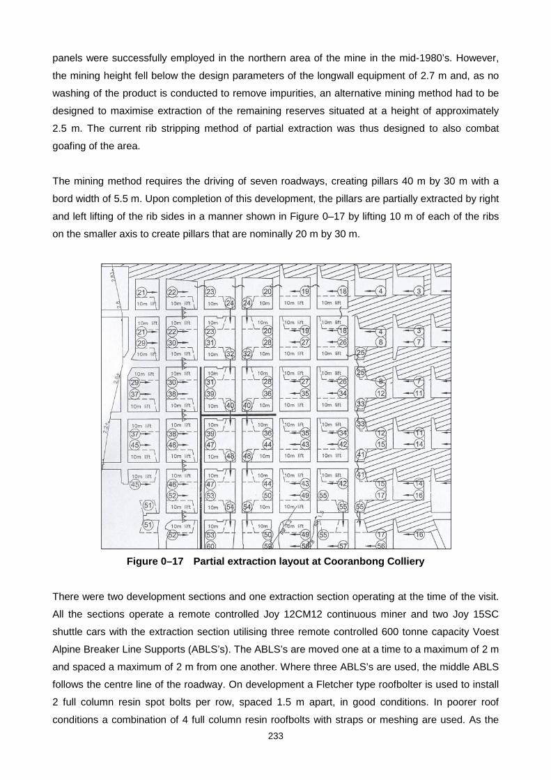
233
panels were successfully employed in the northern area of the mine in the mid-1980’s. However,
the mining height fell below the design parameters of the longwall equipment of 2.7 m and, as no
washing of the product is conducted to remove impurities, an alternative mining method had to be
designed to maximise extraction of the remaining reserves situated at a height of approximately
2.5 m. The current rib stripping method of partial extraction was thus designed to also combat
goafing of the area.
The mining method requires the driving of seven roadways, creating pillars 40 m by 30 m with a
bord width of 5.5 m. Upon completion of this development, the pillars are partially extracted by right
and left lifting of the rib sides in a manner shown in Figure 0–17 by lifting 10 m of each of the ribs
on the smaller axis to create pillars that are nominally 20 m by 30 m.
Figure 0–17 Partial extraction layout at Cooranbong Colliery
There were two development sections and one extraction section operating at the time of the visit.
All the sections operate a remote controlled Joy 12CM12 continuous miner and two Joy 15SC
shuttle cars with the extraction section utilising three remote controlled 600 tonne capacity Voest
Alpine Breaker Line Supports (ABLS’s). The ABLS’s are moved one at a time to a maximum of 2 m
and spaced a maximum of 2 m from one another. Where three ABLS’s are used, the middle ABLS
follows the centre line of the roadway. On development a Fletcher type roofbolter is used to install
2 full column resin spot bolts per row, spaced 1.5 m apart, in good conditions. In poorer roof
conditions a combination of 4 full column resin roofbolts with straps or meshing are used. As the

234
conglomerate roof is generally uneven, a scaling machine is used prior to roofbolting to clear the
roof of any lenses of coal that pose a roof fall hazard. The pillar extraction operation with the use of
ABLS’s is shown in Figure 0–18.
Figure 0–18 Use of ABLS’s during partial extraction at Coornabong Colliery
In addition to the ABLS support, a row of timber breaker props is set on the outbye goaf edge (as
shown in Figure 0–18). This extraction operation yields a production of approximately 750 tonnes
per shift on 14 shifts per week, with one section miner and 5 machine operators per section per
shift. The two development sections produce 550 tonnes per shift each with 19 shifts per week.
Each of the development sections has one section miner and 7 machine operators.
Goafing is localised in its nature and is limited to small areas where sandstone lenses are found.
Although post extraction a span of approximately 26 m is created, the massive conglomerate roof
is capable of spanning the distance successfully and eliminates the risk of a goaf. No adverse

235
effects have been experienced with this mining method, although methane build-up and its
associated frictional ignition hazard is a major safety factor which is negated by forcing ventilation
through the mined out area at 25 m3 per second. The pillars were extracted upon completion of
development resulting in no variation in the yield as no ageing effects were noticed. No surface
subsidence was expected and current measurements have shown little to no effect on the surface
as a result of this mining method.
Review of full pillar extraction operations in New South Wales
Four full pillar extraction operations in New South Wales were visited while some information was
obtained from a fifth operation that has recently ceased this mining practice. Of the four operations
visited, one was in the Southern Coalfield, two in the Western Coalfield and one in the Hunter
Coalfield. All operated under vastly different circumstances and conducted this mining practice for
a variety of reasons. The pertinent factors relating to each of these operations is discussed here.
Review of pillar extraction at Bellambi West Colliery
Bellambi West Colliery operated under unique circumstances in that chain pillars that previously
acted as barrier pillars and main travelling ways between two longwall goaves were extracted. A
modified Wongawilli method was the most suited under the given circumstances. In terms of this
interaction of goaves coupled with the depth of the operation, the focus in its design came in
successfully creating a goaf while creating snooks and fenders large enough to maintain a safe
working environment. The extraction panels were both long and narrow (2,500 m long and 195 m
wide). This panel geometry (when designed in virgin ground) would generally limit full caving and
limit abutment stresses. The panel width to depth below surface (W:D) was 0.46. Generally, for
New South Wales conditions, when the W:D ratio is greater than 1.4, full caving can be expected
and when the ratio is greater than or equal to 2 one can expect surface disturbances. These
guidelines however exist for planning extraction panels in virgin ground and in this case would not
necessarily apply, as the surrounding conditions of the previously created goaf dictated the nature
of the caving. Effectively, these panels acted as a pivot separating previous goaves and extracting
them merely encouraged caving and in so doing consolidated the existing goaves. As a result,
early caving closely followed the extraction line. The subsidence resulting from the operation would
also be an extension of the subsidence already caused by the previous longwall operations.
The extraction at Bellambi West Colliery was an opportunistic decision to maximise the recovery of
reserves to extend the life of the mine. The use of remote controlled continuous miners and
ABLS’s ensured its general success. One of the most important design features of this extraction
method was the leaving of snooks around intersections approximately 12 m2 in area (see Figure 0–

236
3). This translates into the snook having a carrying capacity of 5,500 tonnes. Once a sufficient area
around the snook has been extracted, it will fail under the deadweight load of being 420 m below
surface. The ancillary support from the timber props and the ABLS’s have significantly lower
carrying capacities and serve merely to provide an additional safety zone under which the
continuous miner operator can work, while also controlling the overlying strata and breaking off the
goaf in a controlled fashion.
The change in the extraction sequence (as shown in Figure 0–2 and Figure 0–4) indicated that the
layout shown in Figure 0–4 created a situation whereby caving could not be induced readily in that
the extraction layout was irregular. The change to the more structured layout in Figure 0–2 ensured
that extraction occurred in a straight line and thus created a goaf readily in the same straight line.
Review of pillar extraction at Charbon Colliery
Charbon Colliery operated in unique conditions in terms of the depth below surface being variable
at all times, leading to a continuous dynamic stress regime dependant on location under the
mountainous overburden. The depth below surface of the panel visited varied from 30 m at its most
outbye position, 190 m at the centre and 150 m at its most inbye position.
The modified Wongawilli extraction technique required that the solid side of the panel is developed
regularly with all splits and run outs fully driven before the retreat extraction begins, as opposed to
the goaf side of the panel where the splits and run outs are created and supported only once the
panel has started retreating. Effectively the panel is thus only half developed before the retreat
operation commences. This practice is done to limit the creation of 4-way intersections, which had
in previous instances required expensive cable truss supports as a result of poor geological
conditions. The practice of creating pillars at the last possible moment thus also limited the
interaction of the stresses associated with the previous goaf and minimised the effects of time on
the pillars, as the average age before extraction of these pillars created nearest the previous
goaved panel was one week. Snooks were left in every pillar extracted as depicted in Figure 0–6.
Each of these triangular snooks has an approximate load bearing capacity of 20,000 tonnes (with
an area of 25 m2) while the larger snooks left on the solid side of the pillar (50 m2) are in excess of
50,000 tonnes. As mentioned previously, these larger snooks are left to control return ventilation
and are virtually indestructible in terms of their location and load bearing capacity. The smaller
snooks created on the goaf side of the panel together with the larger snooks of the previous panel
provide support to a 25 m by 20 m area which ensures the area doesn’t collapse and in so doing
ensuring that the return ventilation airway remains open. The smaller 25 m2 snooks in the centre of
the panel are weak enough to collapse when the 30 m wide created span collapses. Each panel
creates a new goaf and the nature of the weak roof ensures that goafing closely follows the

237
extraction line. The nature of the dynamic roof loading conditions, together with the dynamic panel
creation and extraction, make it difficult to quantify the exact nature of the operation, suffice to say
that the extraction operation under these conditions was very successful. Again, the use of timber
props and ABLS’s ensures a safer working environment.
Review of pillar extraction at Ivanhoe Colliery
The full extraction operation at Ivanhoe Colliery is a good example of maximising extraction of a
reserve by extracting existing pillars created by drill and blast methods almost a century ago. The
original design parameters of the area being extracted created pillars of width to height ratio equal
to 10, and the subsequent brushing of the roadways to the full seam height reduced this ratio to 5.6
before extraction commenced. The overall panel width to depth below surface ratio of 6 indicates
that full caving will develop and that surface subsidence will occur (in terms of New South Wales
conditions).
As only single sided lifting is conducted, the approach of leaving snooks is also different from the
double-sided lifting operations. Generally at Ivanhoe Colliery, snooks are left where there are
geological anomalies (stringers, faults, etc.) or where the direction of mining changes. Rather, a
thin fender (approximately 1 m wide) is left at the rear of the pillar being extracted as an additional
support. As it is a thin fender it fails readily under the weight from the roof, thus ensuring that the
goaf line closely follows the extraction process.
Severe rib crush in an area of the panel (resulting from high abutment stresses) resulted in a small
area having to be abandoned. This was a result of the panel being mined out of sequence to mine
an irregular shaped area (marked A on Figure 0–8) which resulted in the pillars at the edge of the
panel being surrounded by goaf on three sides and creating unusual stress regimes in this area. A
further consequence of this area being abandoned is that full caving of adjacent areas was
retarded and resulted in further abutment stress problems for subsequent extraction. In general the
extraction operated under stress as was observed by the rib spall around pillars adjacent to those
being extracted. It is inferred that the age of the pillars are a contributing factor for this, although
other factors such as depth below surface, extraction method, etc. would also have contributed to
this.
Review of pillar extraction at United Colliery
United Colliery has had the benefit of conducting full pillar extraction using a variety of techniques.
The use of the continuous haulage unit obtained variable results with component failure being the
major reason for it being discontinued. The nature of the deposit at United Colliery also played an

238
important role in the overall decision to discard the use of pillar extraction in favour of longwall
mining. The seam dips in the northeast to southwest direction, which is roughly normal to the
number of parallel fault zones, which intersect the entire lease area. The layouts for the extraction
panels lie at approximately 45° to the fault planes, which is common mining practice in New South
Wales. However, the added problem of the seam dip has resulted in the panel layouts dipping
down from right to left when a cross-section of the panel is viewed. In the initial, shallower panels
this was not significant, but in the later, deeper panels it required leaving the centre pillars so as to
reduce the overall span of the panel and in so doing combat severe rib spall and pillar crush which
was more dominant on the pillars on the left hand side (down dip side) of the panel. Figure 0–10
shows that a greater proportion of pillars are extracted on the right hand side of the panel, whereas
the pillars on the left hand side were only partially extracted in an attempt to reduce the effects of
the high stresses encountered there. The panel being extracted also lies between two previously
extracted panels, which have resulted in further high abutment stresses affecting pillar loading in
the extraction panel. It was not uncommon for the pillars to be only partially extracted in an effort to
combat the negative regimes, but this then lead to the panel being a combination of full and partial
extraction which is generally not considered good practice.
The ratio of the width of the panel to its depth below surface of 1.32 indicates that in terms of New
South Wales averages that generally full caving will not occur as this is below 1.4. This creates a
situation whereby caving may or may not occur. Burial of equipment has also occurred regularly as
a consequence of the stresses. Figure 0–19 shows the nature of the most recent equipment burial.
The incident occurred while cutting the last lift and being surrounded by goaf on three sides.
Figure 0–19 Burial of equipment at United Colliery

239
In general, no regular sizes of snooks or fenders have been left as conditions are dynamic and
change from location to location. The decision to replace pillar extraction with longwalling is a
combination of the factors as detailed here, with safety being the major factor behind this decision.
Review of pillar extraction at Chain Valley Colliery
As the Chain Valley Operation was not visited and only limited information could be obtained
pertaining to the extraction method, no analyses or comments can be drawn. Thus, no further
comments regarding the operation can be made.
Review of partial pillar extraction operations in New South Wales
Review of pillar extraction at Clarence Colliery
The partial extraction technique developed for Clarence Colliery required an increase in overall
extraction without caving and in so doing limiting the influx of water associated with two overlying
aquifers, as well as the problems associated with goafing of the overlying massive Triassic
sandstones. The initial panel design of the width of the panel to depth below surface of 0.84
indicates that overall extraction will not induce caving or have surface effects if full extraction is to
be considered. Since only partial extraction is used at Clarence, this ratio becomes less important
than when considered with full extraction operations. The partial extraction method used here
effectively creates two smaller panels within the original panel, separated from one another by the
unmined centre pillars. Once partially extracted, the resulting pillars of 24.5 m by 13.5m are large
enough to aid the massive sandstone roof to span the resultant 16.5 m bord widths. These pillars
have load-bearing capacities of 550,000 tonnes and are considered to be substantial permanent
support. The two lines of centre pillars that are left unmined take the most pressure as a result of
being larger in geometry than the smaller, partially extracted pillars in the panel. The success of
this method has been hampered only by the high rates of extraction achieved and future
modifications to this method will include leaving only one line of centre pillars to further increase
recovery. No use of ABLS’s was made at Clarence Colliery, although a large amount of timber was
used in the form of breaker lines. This method has increased the overall extraction by 10 percent to
45 percent.
Review of pillar extraction at Munmorah Colliery
The partial stripping operation at Munmorah Colliery is different from the other partial extraction
operations in that the centre line of pillars (which remain as a permanent support) is specifically
designed to be larger than the pillars that will be extracted. This would imply that these pillars will
240
take more load from the outset as a result of their larger geometries. The partial extraction of the
two lines of pillars on either side of the centre pillars results in the creation of saw-toothed fenders
approximately 40 m long and 6 m wide. These fenders have a load bearing potential of
approximately 240,000 tonnes. To date there has been no failure of these fenders and they are
thus strong enough in aiding the massive conglomerate roof to span the voids created. Also, no
negative effect to the soft floor has to date been noticed. The original panel design width to depth
below surface ratio of 0.61 is well below the 1.4 required by full caving operations, indicating that
this design is suitable for partial extraction. Further, the positive flood ventilation used has
successfully ensured that previous problems associated with methane and the risk of frictional
ignitions have been minimised. The partial extraction method has also limited the occurrences of
windblasts as the massive conglomerate roof is not broken or caved. It has also increased the
overall recovery from 25 percent to over 80 percent.
Review of pillar extraction at Cooranbong Colliery
The geological situation at Cooranbong Colliery is similar to that experienced at Munmorah Colliery
with the same soft floor conditions and massive conglomerate roof. The partial extraction technique
reduces the 40 m by 30 m pillars to 20 m by 30 m, thus ensuring that these provide an adequate
permanent support of almost 1 million tonnes each. The maximum void created by this method
(25.5 m) is adequately spanned by the massive conglomerate roof. The effects of time have
however resulted in the pillars punching into the soft floor and creating floor heave although this
does not affect the mining method or surface subsidence. The original panel ratio of width to depth
below surface of 4.37 would indicate that full caving and surface interaction would occur if full
extraction were conducted. However, the partial extraction technique creates substantial fenders
that are designed not to fail. This mining method has increased overall extraction from 25 percent
to approximately 75 percent.