tatanka decommissioning plan v4puc.sd.gov/commission/dockets/electric/2019/el19-026/... ·...
TRANSCRIPT

Appendix Q
Decommissioning Plan
4300 MarketPointe Drive, Suite 200 Minneapolis, MN 55435 952.832.2600 www.barr.com
Wind Project Decommissioning Plan
Tatanka Ridge Wind Project
Prepared for Tatanka Ridge Wind, LLC a subsidiary of Avangrid Renewables, LLC
May 2019

P:\Mpls\41 SD\19\41191002 Tatanka Ridge Wind Survey\WorkFiles\Decomissioning Study\Final Plan\Tatanka Decommissioning Plan v4.docx i
Tatanka Ridge Wind Project Decommissioning Plan
May 2019
Contents 1.0 Introduction ........................................................................................................................................................................... 1
1.1 Wind Farm Components ........................................................................................................................................... 1 1.2 Expected Lifetime and Triggering Events .............................................................................................................. 1 1.3 Decommissioning Sequence ...................................................................................................................................... 2
2.0 Decommissioning Components and Activities ........................................................................................................ 4 2.1 Wind Farm System Overview ..................................................................................................................................... 4 2.2 Wind Turbine Generators ............................................................................................................................................ 4 2.3 Step-Up Transformers ................................................................................................................................................ 5 2.4 Wind Turbine Foundations ....................................................................................................................................... 5 2.5 Collection System ........................................................................................................................................................... 6 2.6 Crane Pads ......................................................................................................................................................................... 6 2.7 Access Roads .................................................................................................................................................................... 6 2.8 Project Substation......................................................................................................................................................... 7 2.9 Topsoil Restoration and Revegetation ................................................................................................................... 7
3.0 Decommissioning Cost Estimate Summary ............................................................................................................... 8 3.1 Decommissioning Expenses and Revenues ......................................................................................................... 8 3.2 Net Decommissioning Cost Summary .................................................................................................................10 3.3 Financial Assurance ......................................................................................................................................................10 3.4 Salvage Value .................................................................................................................................................................10
3.4.1 Pricing assumptions ...............................................................................................................................................11 3.5 Markups ............................................................................................................................................................................11 3.6 Escalation Rate ...............................................................................................................................................................11 3.7 Estimate Classification ................................................................................................................................................12 3.8 Cost Resources...............................................................................................................................................................12 3.9 Estimate Methodology ...............................................................................................................................................12 3.10 Labor Costs ......................................................................................................................................................................12 3.11 Sales Tax ...........................................................................................................................................................................12 3.12 Soft Costs .........................................................................................................................................................................12 3.13 Major Assumptions ......................................................................................................................................................12

ii
3.14 Excluded Costs ...............................................................................................................................................................14 4.0 Referenced Documents ...................................................................................................................................................15

iii
List of Tables
Table 1 Primary Components of Wind Farm to be Decommissioned............................................................ 4 Table 2 Typical Access Road Construction Materials ............................................................................................ 7 Table 3 Estimated Decommissioning Expenses and Revenues......................................................................... 9 Table 4 Net Decommissioning Summary ............................................................................................................... 10
List of Figures
Figure 1 Project Location Figure 2 Site Layout

iv
Certifications
May 21, 2019 Joel Bahma, PE
Date

1
1.0 Introduction Tatanka Ridge Wind, LLC (Tatanka Ridge), a wholly owned subsidiary of Avangrid Renewables, LLC, is proposing to construct Tatanka Ridge Wind Project (Project) in Deuel County, South Dakota (Figure 1). The proposed project will generate up to 155 megawatts (MW) of electricity at rated capacity and will include construction of up to 56 turbines a combination of GE 2.82-127 and GE 2.3-116 wind turbine generators (WTG or turbine) Figure 2 shows the site layout.
This Decommissioning Plan report provides a description of the decommissioning and restoration phase of the Project, including a list of the primary wind farm components, dismantling and removal activities, and disposed or recycled materials. A summary of estimated costs and revenues associated with the decommissioning phase is also included.
1.1 Wind Farm Components The main components of the proposed Project include:
Turbines (tower, nacelle, hub, rotor, and three rotor blades per WTG)
Turbine foundations
Step-up transformers
Access road s
Crane pads
Electrical collection system
Meteorological (MET) tower
Substation equipment and foundations
Operation and maintenance (O&M) buildings and foundations
1.2 Expected Lifetime and Triggering Events The anticipated Project life is 40 years from the date of construction. Depending on market conditions and Project viability, the turbines may be refitted with updated components, such as nacelles, towers, and/or blades to extend the life of the Project. In the event that the turbines are not retrofitted, or at the end of the Project's useful life, the turbines and associated components will be decommissioned and removed from the site.
Turbine components that have resale value may be sold in the wholesale market. Components with no wholesale value will be salvaged and sold as scrap for recycling or disposed at an offsite licensed solid waste disposal facility (e.g., landfill). Decommissioning activities will include removal of the turbines and associated components as listed in Section 1.1 and described in Section 2.
2
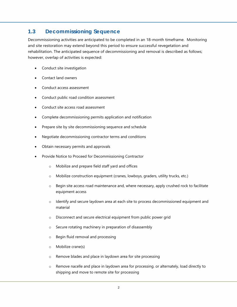
1.3 Decommissioning Sequence Decommissioning activities are anticipated to be completed in an 18-month timeframe. Monitoring and site restoration may extend beyond this period to ensure successful revegetation and rehabilitation. The anticipated sequence of decommissioning and removal is described as follows; however, overlap of activities is expected:
Conduct site investigation
Contact land owners
Conduct access assessment
Conduct public road condition assessment
Conduct site access road assessment
Complete decommissioning permits application and notification
Prepare site by site decommissioning sequence and schedule
Negotiate decommissioning contractor terms and conditions
Obtain necessary permits and approvals
Provide Notice to Proceed for Decommissioning Contractor
o Mobilize and prepare field staff yard and offices
o Mobilize construction equipment (cranes, lowboys, graders, utility trucks, etc.)
o Begin site access road maintenance and, where necessary, apply crushed rock to facilitate equipment access
o Identify and secure laydown area at each site to process decommissioned equipment and material
o Disconnect and secure electrical equipment from public power grid
o Secure rotating machinery in preparation of disassembly
o Begin fluid removal and processing
o Mobilize crane(s)
o Remove blades and place in laydown area for site processing
o Remove nacelle and place in laydown area for processing. or alternately, load directly to shipping and move to remote site for processing

3
o Disassemble tower and place in laydown area for site processing
o Mobilize crane to next site (this may be overland if possible to negotiate with land owners to speed disassembly and avoid multiple over road transport and erection operations)
o Process blades and load for disposal/recycle
o Process tower and load for transport to scrap yard
o Remove underground cable where surfaced
o Remove tower foundation to a depth of 42 inches below final grade using approved means and methods
o Haul tower foundation material to disposal site for reprocessing (concrete to be crushed, rebar for recycle)
o Remove access road and surfacing (gravel) where required
o Haul surfacing material to approved stockpile for reclaim or sale
o Regrade site to appropriate contours
o Prepare soil for seeding
o Seed site
o Complete final clean up

4
2.0 Decommissioning Components and Activities The wind farm components and decommissioning activities necessary to restore the Project area, as near as practicable, to pre-construction conditions are described within this section. Tatanka Ridge will dismantle and remove all towers, turbine generators, transformers, overhead and underground cables, foundations, buildings, and ancillary equipment to a depth of 42 inches unless landowner agreements specify a greater depth. To the extent possible the permittees shall restore and reclaim the site to its pre-project topography and topsoil quality.
Estimated quantities of materials to be removed and salvaged or disposed are included in this section. Public roads damaged or modified during the decommissioning and reclamation process shall be repaired upon completion of the Project.
2.1 Wind Farm System Overview The Project will use a combination of GE127 2.82 MW and GE116 2.3 MW turbines with a total nameplate generating capacity of up to 155 MW. Table 1 presents a summary of the primary components included in this decommissioning plan.
Table 1 Primary Components of Wind Farm to be Decommissioned
Component Quantity Unit of Measure Wind turbines (including one tower, one nacelle, one hub and one rotor with three rotor blades per turbine) 56 Each
Step-up transformers 56 Each
Wind turbine foundations 56 Each
Crane pads or mats 56 Each
Access roads 89,760 Lineal Feet (estimated)
2.2 Wind Turbine Generators The GE127 2.82 MW model wind turbine generators are primarily comprised of a modular steel tower, nacelle, and rotor with three rotor blades attached to a hub. The hub height of the turbines will be 88.5 meters (m) with a 127 m rotor diameter. The GE116 2.3 MW model wind turbine generators have comparable components and share a similar platform, with a hub height of 90 m and with a 116 m rotor diameter. The components of both are modular in design, allowing for ease of construction, replacement, and disassembly during decommissioning. Turbine components in working condition may be refurbished and sold in a secondary market yielding greater revenue than selling as salvage material. For the purposes of this report, estimates will be based on the salvage value, as this will be the most conservative estimate of revenue.

5
Turbine Tower - The turbine towers are painted modular monopole steel structures approximately 88.5 to 90 m long. Each tower contains approximately 172 tons of salvageable steel. It is estimated that the tower sections will be cut down to transportable size and sent to a scrap metal facility for processing.
Nacelle - The nacelle sits at the top of the turbine tower and has an overall weight of approximately 75 tons including the bedplate. The nacelle is comprised of approximately 80% salvageable steel along with other non-salvageable materials. Non-salvageable material within the nacelle will be disposed in a landfill.
Hub, Rotor, and Rotor Blades - The rotor and hub (without blades) has a total weight of approximately 47 tons. It is mainly comprised of steel that will be salvaged along with the tower and nacelle. The rotor blades are constructed of non-metallic materials such as fiberglass, carbon fibers, and epoxies. These materials will likely have no salvage value and will be recycled for a cost.
Other Turbine Components - In addition to the main components previously described, each WTG contains other items such as ladders and platforms, anchor bolts, and internal electrical wiring that will have additional salvage value.
Decommissioning Activity - The wind turbines will be deactivated from the surrounding electrical system and made safe for disassembly. Improvements to access roads and crane pads will be completed to allow crane access to turbines for removal of components. Liquid wastes, including gear box oil and hydraulic fluids will be removed and properly disposed or recycled according to regulations current at the time of decommissioning. Control cabinets, electronic components, and internal electrical wiring will be removed and salvaged. The hub and rotors will be lowered to the ground as a unit for disassembly. The nacelle and turbine sections will be disassembled and removed in the reverse order of assembly.
2.3 Step-Up Transformers After deactivation, oil will be drained and recycled or disposed at an approved solid waste management facility. The transformer will then be disassembled and removed. Depending on condition, the transformers may be sold for refurbishment and re-use. If not re-used, the transformer will be salvaged for raw materials.
2.4 Wind Turbine Foundations Typical spread footing foundations utilized for the Project turbines will be predominantly located underground. Below the pedestal is the foundation base, a typically octagonal-shaped concrete structure. The entire foundation sits on supporting sub-grade typically around 10 feet below the ground surface. At the time of this report, foundation design has not yet been completed.
Concrete demolition will be completed on the upper 42 inches of the pedestal. This will include the anchor bolts, rebar, conduits, cables, and concrete to the required depth. The site will be back-filled

6
with clean fill and graded and the land contours restored as near as practicable to preconstruction conditions. Topsoil will be placed on the disturbed area and revegetated. The cost estimate for the excavation and removal of turbine foundations is conservatively based on the previous foundation design sizes. Material would be demolished and hauled to a landfill.
2.5 Collection System The Project's electrical collection system will be overhead or located in cable trenches that will generally be buried at a depth more than 42 inches below the ground surface. The system voltage is 34.5 kilovolts (kV) and will run from the individual turbine step-up transformers to the Project substation.
The Project collection system would not interfere with farming activities when placed 42 inches or more below ground surface. Hence, complete cable removal is not required at decommissioning to restore the wind farm site to its former use. Cables 42 inches or more below ground surface will be completely deactivated and abandoned in place. Minimal decommissioning costs are associated with the collection system and are included in the turbine decommissioning estimate. If, at the time of decommissioning, the salvage value of the underground cable exceeds the cost of extraction and restoration, the cables may be removed and salvaged.
2.6 Crane Pads Crane pads will be located at the base of each turbine to support the large cranes necessary for assembly and disassembly of the turbines. Pads will be approximately 60 feet by 80 feet and consist of compacted native soils and approximately one half foot of base fill. After decommissioning activities are completed, the crane pad aggregate will be removed and the areas filled with native soil, as necessary. Land will be graded and pre-construction contours restored to the extent practicable. Restoration will likely be performed in conjunction with the turbine foundation and/or access road restoration. Soils compacted during de-construction activities will be de-compacted (ripped to 18 inches), as necessary, to restore the land to preconstruction land use. Labor for trucking and equipment is the primary expense for the crane pad removal.
2.7 Access Roads The Project includes construction of roads to provide access from public roads to the turbine sites. The final width of the roads is approximately 16 feet, widening near the turbine base. The total length of Project access roads is approximately 17 miles. During the initial construction of the wind farm, the existing soils will be graded to match the typical contour of the adjacent land and compacted. The estimated quantity of these materials is provided in Table 2.

7
Table 2 Typical Access Road Construction Materials
Item Number Unit Geotextile 180,000 Square Yards
Aggregate Course 53,200 Cubic Yards
Tatanka Ridge will remove all access roads unless an affected landowner requests otherwise. Tatanka Ridge will record any agreement for removal to a lesser depth or for no removal with the County and show the locations of all such foundations. Tatanka Ridge will submit all such agreements with affected landowners to the County prior to completion of restoration activities. Tatanka Ridge will restore the Project within 18 months after expiration of the issued permit, or upon earlier termination of operation of the Project. The estimate assumes 75% of the roads are to be removed and returned to preconstruction state. Decommissioning activities include the removal and stockpiling of aggregate materials onsite for salvage preparation. Local townships or farmers may accept the material prior to processing for use on local roads or field access roads; however, for the purpose of this estimate it is conservatively assumed that all materials will be removed from the Project area.
Following removal of aggregate, the access road areas will be graded, de-compacted (ripped to 18 inches), back-filled with native soils, as needed, and land contours restored as near as practicable to preconstruction conditions.
While there would likely be some salvage value for the aggregate surface material, this estimate assumes any costs of material to be removed from the site to be offset by those gained by secondary sales. Therefore, no salvage value for aggregate has been estimated.
2.8 Project Substation All equipment, conductors, transformers, steel, wiring, and fencing is to be removed. Footings, underground cabling, and aggregate will be removed from the substation site to a depth of 42 inches. Electrical equipment may have value on the secondary market for refurbishment or scrap. Steel and foundations are to be removed and brought to the landfill. Cost of demolishing the substation was based on crews and a scheduled timeframe. No salvage cost was given to the substation.
2.9 Topsoil Restoration and Revegetation Project sites that have been excavated and back-filled will be graded as previously described to restore land contours as near as practicable to preconstruction conditions. Topsoil will be placed on disturbed areas and seeded with appropriate vegetation to reintegrate it with the surrounding environment. Soils compacted during de-construction activities will be de-compacted, as necessary, to restore the land to preconstruction land use.

8
3.0 Decommissioning Cost Estimate Summary Expenses and revenues associated with decommissioning the Project will be dependent on labor costs and market value of salvageable materials at the time of decommissioning. For the purposes of this report, approximate mid-2018 to early-2019 average market values were used to estimate labor expenses. Fluctuation and inflation of the salvage values or labor costs were not factored into the estimates.
3.1 Decommissioning Expenses and Revenues Project decommissioning will incur costs associated with the disassembly, removal, excavation, and restoration of the proposed wind turbine sites and support infrastructure as described in Section 2. Table 3 summarizes the estimates for activities associated with the major components of the Project.
Revenue from decommissioning the Project will be realized through the sale of wind farm components and construction materials. Turbine components may be sold within a secondary market or as salvage. For purposes of this report, estimated recovery values were based on the salvage value, as this is the more conservative estimate of revenue.
The market value of both steel and copper fluctuate daily, although in the long term, both have generally trended upward. Steel prices are generally more stable than copper. Salvage value estimates were based on a current average price of steel and copper derived from sources including material processing companies and American Metals Market index. The price used to value the steel used in this report is $170 per ton. This factors in a 10-year steel average, scrap yard handling, and processing to mill size (two feet by five feet), and milling. The value of copper, $2.10 per pound ($4,200 per ton) and the value of aluminum at $.47 per pound ($940 per ton) were used in this report. The nacelle was assumed to have approximately 80% salvageable steel content; the hub, gearbox and tower 90%. Table 3 summarizes the potential salvage value for the wind turbine components, transformer, and construction materials.

9
Table 3 Estimated Decommissioning Expenses and Revenues
Activity Decommission or Salvage Unit Number Cost or Salvage
Price per Unit Total
Overhead and management (includes estimated permitting required; 8%) Decommission Lump Sum 1 $531,000 $ 531,000 Mobilization and demobilization (6%) Decommission Lump Sum 1 $398,000 $ 398,000 Access Road Prep Decommission Lump Sum 1 $42,000 $ 42,000 Crane Mob and Operations Decommission Each 56 $31,071 $ 1,740,000 Tower Disassembly Decommission Each 56 $30,250 $ 1,694,000 Blade Demo & Recycling Decommission Each 56 $14,000 $ 784,000 Turbine Foundation Removal Decommission Each 56 $15,839 $ 887,000 Collector Line Removal Decommission Lump Sum 1 $38,000 $ 38,000 Site Restoration (Roads, Turbine & Aux Sites) Decommission Lump Sum 1 $1,314,000 $ 1,314,000 O & M Removal Decommission Lump Sum 1 $55,000 $ 55,000 Substation Demo Decommission Lump Sum 1 $71,000 $ 71,000 MET Tower Demo Decommission Lump Sum 1 $15,000 $ 15,000 Contingency Decommission Percent 20% $1,514,000 $ 1,514,000 Turbine tower (steel) (total per 56 turbines) Salvage Tons per turbine 155 ($170) ($1,475,600) Nacelle (steel) (total per 56 turbines) Salvage Tons per nacelle 67 ($170) ($637,840) Rotor hub (total per 56 turbines) Salvage Tons per hub 31 ($170) ($295,120) Generator/gearbox (total per 56 turbines) Salvage Tons per Gen 19 ($170) ($180,880) Transformer (total per 56 turbines) Salvage Per turbine 1 ($3,600) ($201,600) Copper (total per 56 turbines) Salvage Tons per turbine 5.3 ($4,200) ($1,246,560) Aluminum (total per 56 turbines) Salvage Tons per turbine 2 ($940) ($105,280) Oil disposal Salvage Per turbine 1 $1,000 $56,000 Collector line (aluminum) Salvage Lump Sum 1 ($7,100) ($7,100)

10
3.2 Net Decommissioning Cost Summary The following is a summary of the net estimated cost to decommission the Project, using the information detailed in Sections 3.2 and 3.3. Estimates are based on 2018 prices, with no market fluctuations or inflation considered.
Table 4 Net Decommissioning Summary
Item Cost Decommissioning expenses $9,083,000 Potential revenue - salvage value of turbine components and recoverable materials ($4,093,980)
Net Decommissioning Cost $4,989,020 Per Turbine Decommissioning Cost (based on 56 turbines) $89,090
This engineer's estimate produces a conservative estimate of the cost of decommissioning the Project based on the following considerations:
1. Limited design work has been completed. 2. Quantities based on design work completed. 3. This concept-level (Class IV, per AACEI cost estimate classification system 17R-97) cost estimate is
based on engineering of 1-15% design and is meant for feasibility uses. Costs will change with further design changes. Class IV estimates are typically used for project screening, determination of feasibility, concept evaluation, and preliminary budget approval. The estimated accuracy range for the Total Project Cost as the project is defined is -20% to +30%. The accuracy range is based on professional judgment considering the level of design completed, the complexity of the project and the uncertainties in the project as scoped.
3.3 Financial Assurance Tatanka Ridge will commit to a parent guarantee for financial assurance adequate to pay the entire cost of the decommissioning process. Decommissioning costs will be re-evaluated after the first year of facility operation, then every ten years following. The initial inflation rate will be 2.5% and will be considered when decommissioning costs are re-evaluated.
3.4 Salvage Value Salvage values are considered to be the most variable component of the decommissioning study. Depending on the material, equipment, and salvage opportunities, the means and methods used by the contractor would vary from scrapping materials completely to selling equipment in the secondary market and processing materials and equipment, onsite or at a facility, for future use or scrap value.

11
Assumptions in the salvage values were based on current conditions and processing applications. Many materials that are non-recyclable will likely be sent to a landfill, such as concrete debris, wood, or turbine blades.
3.4.1 Pricing assumptions Material salvage pricing is derived from the American Metals Market Index. Prices below are quoted from scrap yards based on current market prices. The steel price is a 10-year market average. In order to capitalize on these prices, material would need to be shipped to a mill and be cut to size prior to shipment. In this case, most components were assumed to be disassembled in a process similar to erection and cut to shippable size onsite. Ability to reclaim all scrap at this pricing is not likely. Some factor is taken in the pricing to account for an assumed grade of scrap. The following pricing assumptions were used to calculate scrap and waste value. Weights are in gross tons:
Steel $170/ton
Copper $4,200/ton
Aluminum $940/ton
Salvage weight has been estimated, scaled, or has been taken from manufacturer’s technical data sheets. Some resale value of components is likely. In this case, certain transformers and electrical components would be considered to have immediate value on the market because of their longer design life. It is likely that newer components may be installed during the lifetime of the wind farm due to maintenance or failure of older components. This estimate does not make attempts to quantify resale of equipment to a secondary market, rather it makes the assumption that all salvage costs will come from scrapping of raw materials.
3.5 Markups The following typical contractor markups were applied to the Demolition Cost Estimate only:
Contractor Project Management/Overhead 8%
Mobilization/Bond/Insurance 6%
3.6 Escalation Rate Barr Engineering Co. (Barr) has not changed, scaled, or accounted for escalation of costs in the future. Considering the volatility of several markets, construction, energy, and labor, an update to this cost estimate prior to actual decommissioning is recommended. This study quantifies the Project in today’s current market and estimates cost in 2019 dollars.

12
3.7 Estimate Classification This concept-level (Class IV, per AACEI cost estimate classification system 17R-97) cost estimate is based on engineering of 1-15% design and is meant for feasibility uses. Costs will change with further design changes. Class IV estimates are typically used for project screening, determination of feasibility, concept evaluation, and preliminary budget approval. The estimated accuracy range for the Total Project Cost as the project is defined is -20% to +30%. The accuracy range is based on professional judgment considering the level of design completed, the complexity of the Project, and the uncertainties in the Project as scoped.
3.8 Cost Resources The following is a list of the various cost resources used in the development of the cost estimate:
2019 R.S. Means
American Metals Market Index
Barr historical data
Vendor quotes on scrap and shipping associated costs
Estimator judgment
3.9 Estimate Methodology Costs were built up from crews and equipment over an estimated schedule as well as contacting industry professionals for quotes and pricing. Some items, such as the MET tower costs, were lump sum allowances based on similar decommissioning studies.
3.10 Labor Costs The estimate is based upon national labor rates.
3.11 Sales Tax This demolition contract estimate has been assumed to not incur any sales tax.
3.12 Soft Costs The cost estimate does not include any soft costs. Soft costs that would likely be associated with the Project would be engineering, design, permitting, land, legal, and other fees.
3.13 Major Assumptions The estimate is based on the assumption the work will be done on a competitive bid basis and the contractor will have a reasonable amount of time to complete the work. All contractors are equal, with a

13
reasonable project schedule, no overtime, work performed as under a single contract, and no liquidated damages.
This estimate was prepared in February 2019. As with all estimates, it represents a snapshot in time of what is known about the Project and expected to occur. The commodities and energy markets are active at this point in time. Changes in either could have dramatic effects on this estimate. Therefore, this estimate should be viewed in that light and if more than 180 days have passed or there have been significant changes in the commodity markets, this estimate should be updated and reevaluated.
Commodity prices for steel, copper, and aluminum were sourced from the AMM cost index and adjusted based on discussions with scrap vendors. (Different types and grades of metals will vary pricing.)
The site is readily accessible.
Only minor repairs to access roads will be necessary to accommodate crane access.
Turbine blades will be disposed or recycled. Materials will be brought to an approved disposal site within 60 miles.
Only turbine foundation pedestal sections and a portion of the footing is to be removed to 42 inches below grade.
90% of tower steel was estimated to be recoverable.
40% of the generator weight is salvageable copper.
Aluminum ladders, internals, and platforms are estimated to be 2 ton per turbine.
Contractor will be allowed to stage construction to obtain the most efficient workflow possible.
Contractor will not be required to perform work using the same means or methods used to produce this estimate.
Contractor will be allowed to use the most appropriate, safest, and efficient methods available to them at the time of performing the work.
Contractor will secure and provide any required demolition permits or certificates.
Demolition contractor will load salvage materials in appropriate sizes and weights at each site to recycling buyer’s vehicle.
Assumed 89,760 linear feet (17 miles) of access road, 16 feet in nominal width.
Turbine and tower dismantling production is 2 work days per turbine.
Crane movement and setup is separate from dismantling operation.

14
Site restoration includes roadway removal and regrading of site, including deep tilling to remove compaction of soils at the road and tower site. 75% of the road will be removed, 25% will remain.
Salvaged roadway material is stockpiled or delivered within a 20-mile radius of each turbine site. Assumed resale value offsets freight fees.
Half day of decommissioning preparation per site, including oil removal, is allocated prior to crane dismantling.
All recycled material is processed to manageable sizes for transport from site.
All recycled material is provided to recycling vendor Free On Board Shipping Point.
Sales tax is not included; the Project is assumed not to be purchasing major quantities of new materials.
3.14 Excluded Costs The cost estimate excludes the following costs:
Non-construction or soft costs for design, services during construction, land, legal, and owner administration costs.

15
4.0 Referenced Documents This estimate is based upon the following documents:
GIS data 3-27-2019 (Avangrid)
GE 2.0MW Platform – Weights and Dimensions
AMM August 2018 Pricing Index

Figures

Service Layer Credits:
Lake Cochrane
Minnesota
Deue
l Cou
nty
Haml
in Co
unty
Deuel CountyBrookings County
EurekaTownship
LakeHendricksTownship
Oak LakeTownshipPreston
TownshipArgo Township
Clear LakeTownship
NordenTownship
ScandinaviaTownship
Blom Township
BrandtTownship
GrangeTownship
HavanaTownship
HerrickTownship
HidewoodTownship
DempsterTownship
EstellineTownship
HamlinTownship
Estelline
Brandt
Clear Lake
Astoria
Toronto
Barr
Foote
r: ArcG
IS 10
.6.1,
2019
-04-2
4 11:3
1 File
: I:\Pr
ojects
\41\19
\1002
\Map
s\Rep
orts\
Deue
l_Cou
nty_P
ermit_
Appli
catio
n\Fig
01 Pr
oject
Boun
dary.
mxd U
ser: m
bs2
I2 0 2
Miles
3 0 3Kilometers
Figure 1
PROJECT BOUNDARYTatanka Ridge Wind Project
Tatanka Ridge Wind, LLCDeuel County, South Dakota
Project BoundaryMunicipalityCivil Township BoundaryCounty BoundaryState Boundary
!(
IA
MNMT
NE
ND
WY
Topography Source: USGS 24k DRG

Service Layer Credits:
")
!(#*
#*
!!
!!
! ! ! ! ! ! ! !
!!
!!
!
! ! ! ! ! ! ! !
!!
!
!
!
! ! ! ! ! ! ! ! ! ! ! ! ! ! ! ! ! ! !
!!
!
! !
#*
!
!
!
!
!
!
!
!
!
!
!!
!
!
!!
!
!
!
!
!!
!!
!
!
!
!
!
!
!
!!!
!
!
!
!
!
!
!!
!
!
!!
!
!!
!!
!
!
!
!
!
!! !
!!
!
(
(
(
(
(
(
(
(
(
(
((
(
(
((
(
(
(
(
((
((
(
(
(
(
(
(
(
(((
(
(
(
(
(
(
((
(
(
((
(
((
((
(
(
(
(
(
(( (
((
(
!
!
!
!
!
!
!
!
!
!
!
!
!
!
!
!
!
!
!
!
!
!
!
!
!
!
!
!
!
!
!
!
!
!
!
!
!
!
!
!
!
!
!
!
!
!
!
!
!
!
!
!
!
!
!
!
!
!
!
!
!
!
!
!
!
!
!
!
!
! ! ! !
!
!
!
!!
!!
!!
!!
!!
!
!!!
!!
!
!
!
!
! !! ! ! ! ! ! ! !
! ! ! ! ! ! ! ! ! ! ! ! ! ! !
!
!
!
!
!
!
!
471s
tAv
e Wash
ington
St
1st St
Jeffer
son S
t
3rd St47
6th Av
e 479th
Ave
CR 317
CR 2
474th
Ave
191st St
480th
Ave
478th
Ave
190th St
CR 31
5
472n
d Ave
CR 517
482n
d Ave
189th St
193rd St
192nd St
195th St
CR 314
187th St
186th St
470th
Ave
477th
Ave
481s
t Ave
CR 31
3
473rd
Ave
475th
Ave
2828
15
§̈¦29
T114 R48S9
T114 R49S20
T114 R49S21
T114 R49S22
T114 R49S23
T114 R49S24
T114 R49S36
T114 R49S13
T114 R49S14
T114 R49S10
T114 R49S12
T114 R49S17
T114 R49S19
T114 R49S25T114 R49
S27
T114 R49S33
T114 R49S35
T114 R49S7
T114 R49S9
T114 R49S15
T114 R49S16
T114 R49S29T114 R49
S30
T114 R49S31
T114 R50S10 T114 R50
S11
T113 R48S10
T113 R48S11
T113R48S26
T113 R48S27
T113 R48S28T113 R48
S29
T113R48S8
T113 R48S9
T113R49S1
T113 R49S10
T113 R49S23
T113 R49S24
T113 R49S25
T113 R49S26
T113R49S6
T113R49S7
T113 R49S8 T113 R49
S9
T113 R50S22
T113 R50S23
T113 R50S24
T113 R50S36
T113R48S14
T113 R48S16
T113 R48S22
T113 R48S30
T113 R48S32
T113R48S4
T113R48S6
T113 R49S12
T113 R49S14
T113 R49S20
T113 R49S22
T113 R49S27T113 R49
S29
T113 R49S35
T113R49S4
T113 R50S10
T113 R50S12
T113 R50S25T113 R50
S27
T113 R50S35
T113 R48S18
T113 R48S19
T113R48S2
T113 R48S20
T113 R48S33
T113 R48S34
T113R48S35
T113 R49S16
T113 R49S17T113 R49
S18
T113 R49S19
T113 R49S30
T113 R49S31
T113 R49S32
T113 R49S33
T113 R50S13
T113 R50S14T113 R50
S15
T113R50S3
T114R48S11
T114R48S14
T114 R48S27T114 R48
S28T114 R48
S29
T114 R50S12
T114 R50S13
T114 R50S14T114 R50
S15
T114 R48S16T114 R48
S18
T114R48S26T114 R48
S30
T114 R48S32
T114 R48S8
T114 R50S24
T114 R50S26
T114 R50S34
T114 R48S19
T114 R48S20
T114 R48S21
T114 R48S22
T114 R48S34
T114R48S35
T114 R50S22
T114 R50S23
T114 R50S36
T114 R49S11
T114 R49S18
T114 R49S26T114 R49
S28
T114 R49S32
T114 R49S34
T114 R49S8
T113 R48S15
T113 R48S17
T113 R48S21
T113R48S23
T113R48S3
T113 R48S31
T113R48S5
T113R48S7
T113 R49S11
T113 R49S13
T113 R49S15
T113R49S2
T113 R49S21
T113 R49S28
T113R49S3
T113 R49S34
T113 R49S36
T113R49S5T113 R50
S1
T113 R50S11
T113R50S2
T113 R50S26
T113 R50S34
T114 R48S10
T114 R48S15T114 R48
S17
T114R48S23
T114 R48S31
T114 R48S33
T114 R48S7
T114 R50S25T114 R50
S27
T114 R50S35
NordenTownship
ScandinaviaTownship
Blom Township
BrandtTownship
GrangeTownship
HidewoodTownship
PMM
A2
E2
A1
G3
I2
E6
L7
K7
L11L6
H2H1
K8
B1C5
B3
F4
I5
B2
F2
G2G1
E1 E5
J1
I3
H3H5
H4
J2
E3
F1K3K2
K1
P5
L8
L4L3
L5
L2L1
O4
P7
P4P3
K6
P6P1
K4K0 K5
O3
O5
L9
L10
S6S5S8
E4P8
I4
Brandt
Toronto
Barr
Foote
r: ArcG
IS 10
.6.1,
2019
-05-2
1 12:3
6 File
: I:\Pr
ojects
\41\19
\1002
\Map
s\Rep
orts\
Deue
l_Cou
nty_P
ermit_
Appli
catio
n\Fig
04 Pr
oject
Layo
ut.mx
d Use
r: mbs
2
I1 0 1
Miles
Figure 2
PROJECT LAYOUTTatanka Ridge Wind Project
Tatanka Ridge Wind, LLCDeuel County, South Dakota
!( Turbine Location#* Met Tower Location#* Laydown Area!( O&M Building") Substation
Access RoadCollector Line
Underground!
!
! Overhead/UndergroundFinal Alignment To Be DeterminedExisting Underground Pipeline
!
!
!Existing Overhead Transmission LineProject BoundaryMunicipalityPublic Land Survey SectionCivil Township BoundaryCounty Boundary
Imagery Source: USDA NRCS NAIP, 2018
1.5 0 1.5Kilometers