technical documentation bnwas 3000 - deckma gmbh bnwas... · technical documentation bnwas 3000...
TRANSCRIPT


Technical Documentation BNWAS 3000
Tel.: +49 (0)4105 / 65 60 – 0 * DECKMA GmbH * Fax: +49 (0)4105 / 65 60 – 25 E-Mail: [email protected] * Internet: www.deckma-gmbh.de
1.6 Installation instructions Version 2.0 19/06/2017 Page 2 of 22
Table of contents 1. General .................................................................................................................................................... 3 2. Cable requirements .................................................................................................................................. 3 3. Connection of various units ...................................................................................................................... 4 4. Setting the address (REPEATER UNIT) ................................................................................................... 9 5. Accumulator charging............................................................................................................................... 9 6. Pin assignment ........................................................................................................................................ 9
6.1. WATCH ALARM MAIN UNIT ............................................................................................................. 9 6.2. REPEATER UNIT ........................................................................................................................... 14 6.3. SELECTOR UNIT ........................................................................................................................... 15 6.4. RESET UNIT .................................................................................................................................. 16 6.5. BOOSTER UNIT ............................................................................................................................. 17
7. Current .................................................................................................................................................. 18 8. Accumulator ........................................................................................................................................... 18 9. Installation ............................................................................................................................................. 18 10. Audible signal generator ......................................................................................................................... 18 11. Reset sensor.......................................................................................................................................... 19 12. Location ................................................................................................................................................. 19 13. Compass safe distance .......................................................................................................................... 20 14. Commissioning ...................................................................................................................................... 22

Technical Documentation BNWAS 3000
Tel.: +49 (0)4105 / 65 60 – 0 * DECKMA GmbH * Fax: +49 (0)4105 / 65 60 – 25 E-Mail: [email protected] * Internet: www.deckma-gmbh.de
1.6 Installation instructions Version 2.0 19/06/2017 Page 3 of 22
1. General
These installation instructions supplement the documentation of the BNWAS 3000 (system description, operating instruction, technical documentation...). For further information see the relevant documentation for help.
The currently applicable standards must be consulted prior to installation of the BNWAS 3000 and must be observed.
2. Cable requirements
For safe operation of the entire system, the cables shown in the table are recommended.
Connector Cable type Core diameter Cable diameter POWER SUPPLY 100-240V AC (JM2)
Unshielded cable min. 3 x 1.5 mm²
POWER SUPPLY 24V DC (JM1)
Unshielded cable min. 3 x 2.5 mm²
ACCUMULATOR 24V (JB1)
Shielded cable 2 x 2.5 mm²
REPEATER UNIT (JR1, JR2)
Shielded twisted-pair cable 3 x 2 x 0.75 mm²
RESET UNIT (JQ1) Shielded twisted-pair cable min. 2 x 2 x 0.75 mm² 1 5-10mm SERIAL out 1 (JV1) Shielded twisted-pair cable 3 x 0.75 mm² SERIAL out 2 (JV2) Shielded standard serial cable SERIAL in 1 (JG1) Shielded twisted-pair cable 5 x 0.75 mm² SERIAL in 2 (JA1) Shielded twisted-pair cable 5 x 0.75 mm² RESET SENSOR (JE1)
Unshielded cable min. 4 x 0.75 mm² 2
RELAY OUTPUT (JK1) Unshielded cable min. 9 x 1.0 mm² 3 AUTO MODE ON/OFF; ext. Signal Generator
Unshielded cable 5 x 0.75 mm²
1 Cable diameter depends on cable length and number of UNITs. 2 Cable diameter depends on current and voltage. 3 Cable diameter depends on connected siren(s), current and voltage.

Technical Documentation BNWAS 3000
Tel.: +49 (0)4105 / 65 60 – 0 * DECKMA GmbH * Fax: +49 (0)4105 / 65 60 – 25 E-Mail: [email protected] * Internet: www.deckma-gmbh.de
1.6 Installation instructions Version 2.0 19/06/2017 Page 4 of 22
3. Connection of various units

Technical Documentation BNWAS 3000
Tel.: +49 (0)4105 / 65 60 – 0 * DECKMA GmbH * Fax: +49 (0)4105 / 65 60 – 25 E-Mail: [email protected] * Internet: www.deckma-gmbh.de
1.6 Installation instructions Version 2.0 19/06/2017 Page 5 of 22
Wiring diagram BNWAS 3000 without SELECTOR UNIT

Technical Documentation BNWAS 3000
Tel.: +49 (0)4105 / 65 60 – 0 * DECKMA GmbH * Fax: +49 (0)4105 / 65 60 – 25 E-Mail: [email protected] * Internet: www.deckma-gmbh.de
1.6 Installation instructions Version 2.0 19/06/2017 Page 6 of 22

Technical Documentation BNWAS 3000
Tel.: +49 (0)4105 / 65 60 – 0 * DECKMA GmbH * Fax: +49 (0)4105 / 65 60 – 25 E-Mail: [email protected] * Internet: www.deckma-gmbh.de
1.6 Installation instructions Version 2.0 19/06/2017 Page 7 of 22
Wiring diagram BNWAS 3000 with SELECTOR UNIT

Technical Documentation BNWAS 3000
Tel.: +49 (0)4105 / 65 60 – 0 * DECKMA GmbH * Fax: +49 (0)4105 / 65 60 – 25 E-Mail: [email protected] * Internet: www.deckma-gmbh.de
1.6 Installation instructions Version 2.0 19/06/2017 Page 8 of 22

Technical Documentation BNWAS 3000
Tel.: +49 (0)4105 / 65 60 – 0 * DECKMA GmbH * Fax: +49 (0)4105 / 65 60 – 25 E-Mail: [email protected] * Internet: www.deckma-gmbh.de
1.6 Installation instructions Version 2.0 19/06/2017 Page 9 of 22
4. Setting the address (REPEATER UNIT)
The REPEATER UNIT functions as a slave within a bus system from where it receives all system relevant data. Up to four (4) REPEATER UNITs can be connected to the BNWAS 3000 system, each UNIT requires its own, unique address on the bus. The address can be set by connecting pin 6 and/or pin 7 of connector JR1 to ground potential (0V).
Pin 6 Pin 7 Address
- - 1 Ground (0V) - 2 - Ground (0V) 3 Ground (0V) Ground (0V) 4
If the system is configured for one (1) REPEATER UNIT only, only address “1” must be set. If the system has been configured for two (2) UNITs, address “2” must be added, for three (3) UNITs “3” and for the maximum number of four (4) UNITs the address “4”. If the address no longer corresponds to the system configuration, an error is generated.
5. Accumulator charging
The accumulator is charged via a current control circuitry. The current can be adjusted with a simple external resistor connected between pin 3 and pin 4 on the 24V ACCUMULATOR connector (JB1).
Resistor Current
0 - 500 Ω 200 mA 0.800 – 1.200 KΩ 150 mA 1.500 - 3 KΩ 100 mA No resistor – or open connection 50 mA
6. Pin assignment
6.1. WATCH ALARM MAIN UNIT
Pin assignment POWER SUPPLY 24 V DC 3-pole Weidmüller RM5.08 JM1
1 24 V in Power supply 24 V DC (input) 2 GND GND 3 PE Shield

Technical Documentation BNWAS 3000
Tel.: +49 (0)4105 / 65 60 – 0 * DECKMA GmbH * Fax: +49 (0)4105 / 65 60 – 25 E-Mail: [email protected] * Internet: www.deckma-gmbh.de
1.6 Installation instructions Version 2.0 19/06/2017 Page 10 of 22
Pin assignment POWER SUPPLY 100-240 VAC 3-pole Phoenix RM 5.08 JM2
1 N in 100...240 VAC 2 L in Neutral 3 PE Shield
Pin assignment ACCUMULATOR 24 V 5-pole Weidmüller RM 5.08 JB1
1 BP 24 V 2 BM GND 3 SC A Charging current selection 4 SC B Charging current selection 5 PE Shield
Charging current selection
Resistor Charge current Suitable for accumulators
510R max. 200 mA > 2 A/h 1k max. 150 mA > 1.5 A/h 2k max. 100 mA > 1 A/h None max. 50 mA > 0.5 A/h
Pin assignment RESET UNIT 5-pole Weidmüller RM 5.08 JQ1
1 24 V out Power supply 24 V (output) 2 LED1 out LED 1 3 LED2 out LED 2 4 RESET in Reset (acknowledge) 5 GND GND

Technical Documentation BNWAS 3000
Tel.: +49 (0)4105 / 65 60 – 0 * DECKMA GmbH * Fax: +49 (0)4105 / 65 60 – 25 E-Mail: [email protected] * Internet: www.deckma-gmbh.de
1.6 Installation instructions Version 2.0 19/06/2017 Page 11 of 22
Pin assignment REPEATER UNIT 5-pole Weidmüller RM 3.5 JR1 JR2
1 PE Shield 2 RS485-A RS485-A (bus connection to a REPEATER UNIT) 3 RS485-B RS485-B (bus connection to a REPEATER UNIT) 4 GND GND 5 24 V out Power supply 24 V (output)
Pin assignment
AUTO MODE ON/OFF 5-pole Phoenix RM 5.08 JPI1 and ext. Signal Generator 1 24 V out Power supply 24 V for signal generator 2 SIGNAL out External signal generator 3 NC Not connected 4 AUTO in AUTO MODE ON/OFF 5 GND GND
Pin assignment SERIAL out 1 4-pole Weidmüller RM 3.5 JV1
1 RS485-A RS485-A (for event- and alarm messages output) 2 RS485-B RS485-B (for event- and alarm messages output) 3 GND GND 4 PE Shield

Technical Documentation BNWAS 3000
Tel.: +49 (0)4105 / 65 60 – 0 * DECKMA GmbH * Fax: +49 (0)4105 / 65 60 – 25 E-Mail: [email protected] * Internet: www.deckma-gmbh.de
1.6 Installation instructions Version 2.0 19/06/2017 Page 12 of 22
Pin assignment SERIAL out 2 9-pin D- Sub (female) connector JV2
1 2 TXD RS232 TxD (for service messages) 3 RXD RS232 RxD (for service messages) 4 5 GND GND 6 7 8 9
Pin assignment SERIAL in 1 6-pole Weidmüller RM 3.5 JG1
1 PE Shield 2 RXD RS232 RxD (for serial reset & time and date read-in) 3 TXD RS232 TxD (for serial reset & time and date read-in) 4 RS485-A RS485-A (for serial reset & time and date read-in) 5 RS485-B RS485-B (for serial reset & time and date read-in) 6 GND GND
Pin assignment SERIAL in 2 6-pole Weidmüller RM 3.5 JA1
1 PE Shield 2 RXD RS232 RxD (for serial reset & time and date read-in) 3 TXD RS232 TxD (for serial reset & time and date read-in) 4 RS485-A RS485-A (for serial reset & time and date read-in) 5 RS485-B RS485-B (for serial reset & time and date read-in) 6 GND GND

Technical Documentation BNWAS 3000
Tel.: +49 (0)4105 / 65 60 – 0 * DECKMA GmbH * Fax: +49 (0)4105 / 65 60 – 25 E-Mail: [email protected] * Internet: www.deckma-gmbh.de
1.6 Installation instructions Version 2.0 19/06/2017 Page 13 of 22
Pin assignment RESET SENSOR 4-pole Phoenix RM 5.08 JE1
1 SABOT in Sabotage 2 RESET in Reset sensor electronics 3 12V out Power supply for reset sensor electronics 12V (max. 100 mA) 4 GND GND
Pin assignment RELAY OUTPUT 9-pole Weidmüller RM 3.5 JK1
1 K1 NO 2. Alarm relay normally open 2 K1 CM 2. Alarm relay common 3 K1 NC 2. Alarm relay normally closed 4 K2 NO 3. Alarm relay normally open 5 K2 CM 3. Alarm relay common 6 K2 NC 3. Alarm relay normally closed 7 K3 NO Fault relay normally open 8 K3 CM Fault relay common 9 K4 NC Fault relay normally closed

Technical Documentation BNWAS 3000
Tel.: +49 (0)4105 / 65 60 – 0 * DECKMA GmbH * Fax: +49 (0)4105 / 65 60 – 25 E-Mail: [email protected] * Internet: www.deckma-gmbh.de
1.6 Installation instructions Version 2.0 19/06/2017 Page 14 of 22
6.2. REPEATER UNIT
Pin assignment WATCH ALARM MAIN UNIT 5-pole Weidmüller RM 3.5 JR1
1 PE Shield 2 RS485-A RS485-A (for connection to a WATCH ALARM MAIN UNIT) 3 RS485-B RS485-B (for connection to a WATCH ALARM MAIN UNIT) 4 GND GND 5 24 V in Power supply 24 V input 6 ADR 0 Address “0” 7 ADR 1 Address “1” 8 NC Not connected

Technical Documentation BNWAS 3000
Tel.: +49 (0)4105 / 65 60 – 0 * DECKMA GmbH * Fax: +49 (0)4105 / 65 60 – 25 E-Mail: [email protected] * Internet: www.deckma-gmbh.de
1.6 Installation instructions Version 2.0 19/06/2017 Page 15 of 22
6.3. SELECTOR UNIT
Pin assignment POWER SUPPLY 24 V DC 3-pole Weidmüller RM 5.08 JM1
1 24 V in Power supply 24 V (optional) 2 GND GND 3 PE Shield
Pin assignment WATCH ALARM MAIN UNIT 5-pole Weidmüller RM 3.5 JR1
1 PE Shield 2 RS485-A in RS485-A (for connection to a REPEATER UNIT - input) 3 RS485-B in RS485-B (for connection to a REPEATER UNIT - input) 4 GND GND 5 24 V in Power supply 24 V - input
Pin assignment REPEATER UNIT 5-pole Weidmüller RM 3.5 JR11...JR14
1 PE Shield 2 RS485-A out RS485-A (for connection to a REPEATER UNIT - output) 3 RS485-B out RS485-B (for connection to a REPEATER UNIT - output) 4 GND GND 5 24 V out Power supply 24 V - output

Technical Documentation BNWAS 3000
Tel.: +49 (0)4105 / 65 60 – 0 * DECKMA GmbH * Fax: +49 (0)4105 / 65 60 – 25 E-Mail: [email protected] * Internet: www.deckma-gmbh.de
1.6 Installation instructions Version 2.0 19/06/2017 Page 16 of 22
6.4. RESET UNIT
Pin assignment WATCH ALARM MAIN UNIT 5-pole Weidmüller RM 3.5 JQ1
1 24 V in Power supply 24 V (input) 2 LED1 in LED1 3 LED2 in LED2 4 RESET out Reset (acknowledge) 5 GND GND
Technical Documentation BNWAS 3000
Tel.: +49 (0)4105 / 65 60 – 0 * DECKMA GmbH * Fax: +49 (0)4105 / 65 60 – 25 E-Mail: [email protected] * Internet: www.deckma-gmbh.de
1.6 Installation instructions Version 2.0 19/06/2017 Page 17 of 22
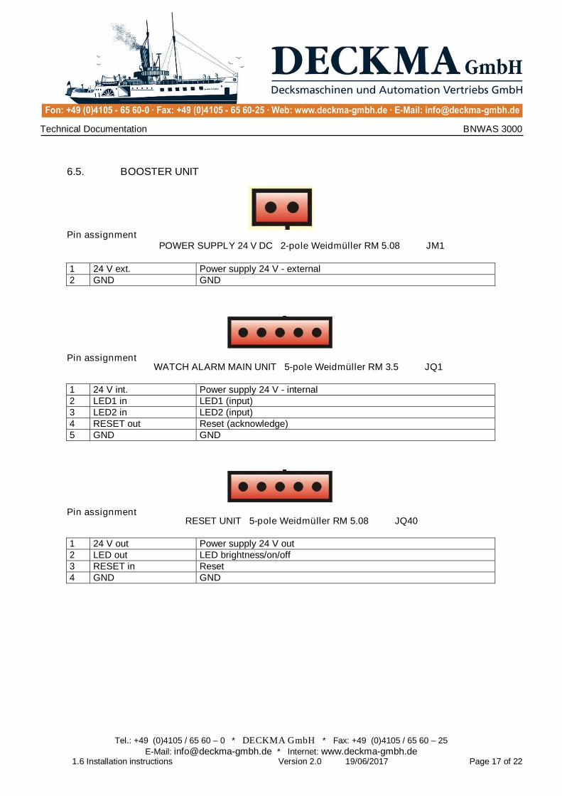
6.5. BOOSTER UNIT
Pin assignment POWER SUPPLY 24 V DC 2-pole Weidmüller RM 5.08 JM1
1 24 V ext. Power supply 24 V - external 2 GND GND
Pin assignment WATCH ALARM MAIN UNIT 5-pole Weidmüller RM 3.5 JQ1
1 24 V int. Power supply 24 V - internal 2 LED1 in LED1 (input) 3 LED2 in LED2 (input) 4 RESET out Reset (acknowledge) 5 GND GND
Pin assignment RESET UNIT 5-pole Weidmüller RM 5.08 JQ40
1 24 V out Power supply 24 V out 2 LED out LED brightness/on/off 3 RESET in Reset 4 GND GND

Technical Documentation BNWAS 3000
Tel.: +49 (0)4105 / 65 60 – 0 * DECKMA GmbH * Fax: +49 (0)4105 / 65 60 – 25 E-Mail: [email protected] * Internet: www.deckma-gmbh.de
1.6 Installation instructions Version 2.0 19/06/2017 Page 18 of 22
7. Current
The WATCH ALARM MAIN UNIT supplies the BNWAS 3000 (the whole system with all the associated and connected UNITs) with power. For this reason the BNWAS 3000 installation must be configured that way, that the overall current of the WATCH ALARM MAIN UNIT is not exceeded.
Note: Several UNITs can be connected to their own power source and can also supply other UNITs with power. A Microsoft EXCEL-table for precise calculation of the whole system configuration is available from DECKMA-GmbH (Consumption BNWAS xxxxx.xls).
8. Accumulator
The size of the accumulator (capacity) must be chosen accordingly to supply the BNWAS 3000 for at least 6 hours of independent run.
9. Installation
The installation of all WATCH ALARM MAIN UNITs, REPEATER UNITs and the SELECTOR UNIT are designed for installation in mounting panels (dimensions for cut-out: width = 72 mm, height = 144 mm).
The BOOSTER UNIT must be mounted on a top-hat DIN-rail in a panel or control cabinet.
The RESET UNIT (open frame) must be panel- or wall-mounted and must be protected against manipulation with special screws.
The RESET UNIT (watertight) must be panel- or wall-mounted and must be protected against manipulation with special screws.
It should be noted, that connectors, cables and housing openings are not accessible and the system is tamper-proof.
All components, except for the RESET UNIT (watertight), must be installed in closed areas and should be protected from any moisture.
10. Audible signal generator
The tone sequence (characteristic beeping) can be configured via the service menu entry. The default setting is a long tone and a long interval.
The sound pressure should reach the level from 75dB(A) to 85dB(A). If the internal signal generator is not loud enough, an external audible signal generator must be connected to JE1.
The signal generators for the second and third alarm must be chosen and installed accordingly to the applicable standards.

Technical Documentation BNWAS 3000
Tel.: +49 (0)4105 / 65 60 – 0 * DECKMA GmbH * Fax: +49 (0)4105 / 65 60 – 25 E-Mail: [email protected] * Internet: www.deckma-gmbh.de
1.6 Installation instructions Version 2.0 19/06/2017 Page 19 of 22
11. Reset sensor
The reset sensor electronic can be supplied from a 12 V power supply. The current must be less than 100 mA and must not exceed the total current (see Current, page 18).
A reset may only be performed by persons on the bridge.
12. Location
The RESET UNITs or the WATCH ALARM MAIN UNIT must be clearly visible and easy accessible from the conning position, workstation for navigation, maneuvering position, workstation for monitoring and bridge wing.
The RESET UNIT and the WATCH ALARM MAIN UNIT must be installed to allow easiest access.
Flashing mushroom buttons (WATCH ALARM MAIN UNIT, RESET UNIT) must be clearly visible to the OOW from any point on the bridge.
The alarm of the WATCH ALARM MAIN UNIT (1st alarm) must be clearly audible to the OOW from any point on the bridge. If external areas are to be included, the external signal generator output must be used.

Technical Documentation BNWAS 3000
Tel.: +49 (0)4105 / 65 60 – 0 * DECKMA GmbH * Fax: +49 (0)4105 / 65 60 – 25 E-Mail: [email protected] * Internet: www.deckma-gmbh.de
1.6 Installation instructions Version 2.0 19/06/2017 Page 20 of 22
13. Compass safe distance

Technical Documentation BNWAS 3000
Tel.: +49 (0)4105 / 65 60 – 0 * DECKMA GmbH * Fax: +49 (0)4105 / 65 60 – 25 E-Mail: [email protected] * Internet: www.deckma-gmbh.de
1.6 Installation instructions Version 2.0 19/06/2017 Page 21 of 22

Technical Documentation BNWAS 3000
Tel.: +49 (0)4105 / 65 60 – 0 * DECKMA GmbH * Fax: +49 (0)4105 / 65 60 – 25 E-Mail: [email protected] * Internet: www.deckma-gmbh.de
1.6 Installation instructions Version 2.0 19/06/2017 Page 22 of 22
14. Commissioning
The BNWAS 3000 must be configured as described in the operating instructions (accumulator charging current, REPEATER UNIT address, configuration menu) followed by a functional test. It must be ensured, that no error messages are generated and all functions work correctly as described. Any faults must be cleared.
All standards and specifications relevant for installation must be observed!
Following commissioning and acceptance, the configuration must be documented as a basic setting in the service menu on the connected computer. For this purpose, a "C" for setting the UTC (GMT) time must be sent first, followed by an "s" for the status/configuration menu, and after at least five minutes, an "e" for error messages and finally an "m" for the module list. The stored data must be handed out to the customer in the form of a log sheet with date and signature together with the delivery document. The configuration data stored on the service computer is archived with the customer order number.