technical manual - add docshare01.docshare.tips to...
TRANSCRIPT
www.nov.com/mdtotco
Technical Manual
Wellsite Gas Watch™
Wireless Portable Monitor 1000
REFERENCE REFERENCE DESCRIPTION
This document contains proprietary and confidential information which belongs to Varco, LP; it is loaned for limited purposes only and remains the property of Varco, LP. Reproduction, in whole or in part; or use of this design or distribution of this information to others is not permitted without the express written consent of Varco, LP. This document is to be returned to Varco, LP upon request and in any event upon completion of the use for which it was loaned.© Varco, LP
M/D Totco1200 Cypress creek RoadCedar Park, Texas 78613USAPhone 512-340-5000Fax 512-340-5219
DOCUMENT NUMBER
42TM50-25REV
A

Document number 42TM50-25Revision APage 1 of 48
www.nov.com/mdtotco
Revision History
Change Description
A 03.31.2006 Issued for ImplementationRev Date Reason for issue Prepared Checked Approved
Revision Change DescriptionA First Issue

Table of Contents
Document number 42TM50-25Revision APage 3 of 48
www.nov.com
Chapter 1: General InformationConventions . . . . . . . . . . . . . . . . . . . . . . . . . . . . . . . . . . . . . . . . . . . . . . . . . . . . . . . . . 5
Notes, Cautions, and Warnings . . . . . . . . . . . . . . . . . . . . . . . . . . . . . . . . . . . . . . . . 5Illustrations . . . . . . . . . . . . . . . . . . . . . . . . . . . . . . . . . . . . . . . . . . . . . . . . . . . . . . . 5
Safety Requirements . . . . . . . . . . . . . . . . . . . . . . . . . . . . . . . . . . . . . . . . . . . . . . . . . . 6Personnel Training . . . . . . . . . . . . . . . . . . . . . . . . . . . . . . . . . . . . . . . . . . . . . . . . . 6Recommended Tools . . . . . . . . . . . . . . . . . . . . . . . . . . . . . . . . . . . . . . . . . . . . . . . 6General System Safety Practices . . . . . . . . . . . . . . . . . . . . . . . . . . . . . . . . . . . . . . 6Replacing Components . . . . . . . . . . . . . . . . . . . . . . . . . . . . . . . . . . . . . . . . . . . . . . 6Routine Maintenance . . . . . . . . . . . . . . . . . . . . . . . . . . . . . . . . . . . . . . . . . . . . . . . 7Proper Use of Equipment . . . . . . . . . . . . . . . . . . . . . . . . . . . . . . . . . . . . . . . . . . . . 7
Chapter 2: Set UpIntroduction . . . . . . . . . . . . . . . . . . . . . . . . . . . . . . . . . . . . . . . . . . . . . . . . . . . . . . . . . 9Information . . . . . . . . . . . . . . . . . . . . . . . . . . . . . . . . . . . . . . . . . . . . . . . . . . . . . . . . . 10Well Information Sheet . . . . . . . . . . . . . . . . . . . . . . . . . . . . . . . . . . . . . . . . . . . . . . . 11Packing and Unpacking. . . . . . . . . . . . . . . . . . . . . . . . . . . . . . . . . . . . . . . . . . . . . . . 12
Case 1, Trap Case . . . . . . . . . . . . . . . . . . . . . . . . . . . . . . . . . . . . . . . . . . . . . . . . 13Case 2, Sensor Case . . . . . . . . . . . . . . . . . . . . . . . . . . . . . . . . . . . . . . . . . . . . . . 14Case 3, Laptop Case . . . . . . . . . . . . . . . . . . . . . . . . . . . . . . . . . . . . . . . . . . . . . . . 15
Rig Up Procedure . . . . . . . . . . . . . . . . . . . . . . . . . . . . . . . . . . . . . . . . . . . . . . . . . . . . 16Wellsite Trailer . . . . . . . . . . . . . . . . . . . . . . . . . . . . . . . . . . . . . . . . . . . . . . . . . . . . 16Rig . . . . . . . . . . . . . . . . . . . . . . . . . . . . . . . . . . . . . . . . . . . . . . . . . . . . . . . . . . . . . 17
Trap Set Up . . . . . . . . . . . . . . . . . . . . . . . . . . . . . . . . . . . . . . . . . . . . . . . . . . . 17Drying System . . . . . . . . . . . . . . . . . . . . . . . . . . . . . . . . . . . . . . . . . . . . . . . . . 19Wireless Gas Monitor Seasonal Operation . . . . . . . . . . . . . . . . . . . . . . . . . . . 22LED Plate . . . . . . . . . . . . . . . . . . . . . . . . . . . . . . . . . . . . . . . . . . . . . . . . . . . . 23
WITS . . . . . . . . . . . . . . . . . . . . . . . . . . . . . . . . . . . . . . . . . . . . . . . . . . . . . . . . . . . 23M/D Totco – RigSense/Iris . . . . . . . . . . . . . . . . . . . . . . . . . . . . . . . . . . . . . . . 24Interfacing to the Electronic Drilling Recorder . . . . . . . . . . . . . . . . . . . . . . . . . 25RigSense Rig Up . . . . . . . . . . . . . . . . . . . . . . . . . . . . . . . . . . . . . . . . . . . . . . 26
Setting Up Well Information . . . . . . . . . . . . . . . . . . . . . . . . . . . . . . . . . . . . . . . . . . . 27
Chapter 3: OperationsKey Laptop Functions . . . . . . . . . . . . . . . . . . . . . . . . . . . . . . . . . . . . . . . . . . . . . . . . 31
Time Log . . . . . . . . . . . . . . . . . . . . . . . . . . . . . . . . . . . . . . . . . . . . . . . . . . . . . . . . 31Depth Log . . . . . . . . . . . . . . . . . . . . . . . . . . . . . . . . . . . . . . . . . . . . . . . . . . . . . . . 34LAS/ASCII File Creation . . . . . . . . . . . . . . . . . . . . . . . . . . . . . . . . . . . . . . . . . . . . 36Alarms . . . . . . . . . . . . . . . . . . . . . . . . . . . . . . . . . . . . . . . . . . . . . . . . . . . . . . . . . . 37
Shut Down . . . . . . . . . . . . . . . . . . . . . . . . . . . . . . . . . . . . . . . . . . . . . . . . . . . . . . . . . 39
/mdtotco

Table of Contents
Document number 42TM50-25Revision APage 4 of 48
Chapter 4: Maintenance and TroubleshootingDaily Maintenance . . . . . . . . . . . . . . . . . . . . . . . . . . . . . . . . . . . . . . . . . . . . . . . . . . . 41
Trap . . . . . . . . . . . . . . . . . . . . . . . . . . . . . . . . . . . . . . . . . . . . . . . . . . . . . . . . . . . . 41Sensor . . . . . . . . . . . . . . . . . . . . . . . . . . . . . . . . . . . . . . . . . . . . . . . . . . . . . . . . . . 41Gas Sample Lines . . . . . . . . . . . . . . . . . . . . . . . . . . . . . . . . . . . . . . . . . . . . . . . . . 42
Troubleshooting . . . . . . . . . . . . . . . . . . . . . . . . . . . . . . . . . . . . . . . . . . . . . . . . . . . . 42No Depth or ROP . . . . . . . . . . . . . . . . . . . . . . . . . . . . . . . . . . . . . . . . . . . . . . . . . 42No Gas . . . . . . . . . . . . . . . . . . . . . . . . . . . . . . . . . . . . . . . . . . . . . . . . . . . . . . . . . 42No Flow . . . . . . . . . . . . . . . . . . . . . . . . . . . . . . . . . . . . . . . . . . . . . . . . . . . . . . . . . 42
Helpful Information . . . . . . . . . . . . . . . . . . . . . . . . . . . . . . . . . . . . . . . . . . . . . . . . . . 44Lag Rate Determination . . . . . . . . . . . . . . . . . . . . . . . . . . . . . . . . . . . . . . . . . . . . 44M/D Totco Drilling Recorder Information . . . . . . . . . . . . . . . . . . . . . . . . . . . . . . . . 47Chimo Troubleshooting . . . . . . . . . . . . . . . . . . . . . . . . . . . . . . . . . . . . . . . . . . . . . 47
www.nov.com/mdtotco
Document number 42TM50-25Revision APage 5 of 48
1: General Information
This manual contains installation, operation, maintenance and parts information. Information in this manual should enable qualified personnel to install, operate and troubleshoot this system. Every effort has been made to ensure the accuracy of the information contained herein. M/D Totco, a National Oilwell Varco company, will not be held liable for errors in this material, or for consequences arising from misuse of this material.
ConventionsNotes, Cautions, and WarningsNotes, cautions, and warnings provide readers with additional information and advise the reader to take specific action to protect personnel from potential injury or lethal conditions. They may also inform the reader of actions necessary to prevent equipment damage. Please pay close attention to these advisories
IllustrationsIllustrations (figures) provide a graphical representation of equipment components or screen snapshots for use in identifying parts or establishing nomenclature, and may or may not be drawn to scale.
For component information specific to your application, see the technical drawings included with your M/D Totco documentation.
Note: The note symbol indicates that additional information is provided about the current topics.
Caution: The caution symbol indicates that potential damage to equipment or injury to personnel exists. Follow instructions explicitly. Extreme care should be taken when performing operations or procedures preceded by this caution symbol.
Warning: The warning symbol indicates a definite risk of equipment damage or danger to personnel. Failure to observe and follow proper procedures could result in serious or fatal injury to personnel, significant property loss, or significant equipment damage.
ESD Warning:
The ESD (Electrostatic Discharge) warning symbol indicates that static control precautions are needed.
www.nov.com/mdtotco

Document number 42TM50-25Revision APage 6 of 48
1: General Information
Safety RequirementsM/D Totco equipment is installed and operated in a controlled drilling rig environment involving hazardous situations. Proper maintenance is important for safe and reliable operation. Procedures outlined in M/D Totco manuals are the recommended methods of performing operations and maintenance.
Personnel TrainingAll personnel performing installation, operations, repair, or maintenance procedures on the equipment, or those in the vicinity of the equipment, should be trained on rig safety, tool operation, and maintenance to ensure their safety.
Recommended ToolsService operations may require the use of tools designed specifically for the purpose described. M/D Totco recommends that only those tools specified be used when stated. Ensure that personnel and equipment safety are not jeopardized when following service procedures or using tools not specifically recommended by M/D Totco.
General System Safety PracticesThe equipment discussed in this manual may require or contain one or more utilities, such as electrical, hydraulic, pneumatic, or cooling water.
Isolate energy sources before beginning work.
Avoid performing maintenance or repairs while the equipment is in operation.
Wear proper protective equipment during equipment installation, maintenance, or repair.
Replacing ComponentsVerify that all components (such as cables, hoses, etc.) are tagged and labeled during assembly and disassembly of equipment to ensure correct installment.
Replace failed or damaged components with genuine M/D Totco parts. Failure to do so could result in equipment damage or injury to personnel.
To avoid injury to personnel or equipment damage, carefully observe requirements outlined in this section.
Personnel should wear protective gear during installation, maintenance, and certain operations.
Read and follow the guidelines below before installing equipment or performing maintenance to avoid endangering exposed persons or damaging equipment.
8
www.nov.com/mdtotco

Document number 42TM50-25Revision APage 7 of 48
1: General Information
Routine MaintenanceEquipment must be maintained on a routine basis. See the service manual for maintenance recommendations.
Proper Use of EquipmentM/D Totco equipment is designed for specific functions and applications, and should be used only for its intended purpose.
Failure to conduct routine maintenance could result in equipment damage or injury to personnel.
www.nov.com/mdtotco

Document number 42TM50-25Revision APage 8 of 48
1: General Information
8
www.nov.com/mdtotco
Document number 42TM50-25Revision APage 9 of 48
2: Set Up
IntroductionThe M/D Totco Wellsite Gas Watch™ MC3 wireless portable gas monitor is a valuable tool for the evaluation of hydrocarbon gases liberated, produced, and recycled while drilling. The system has been engineered to keep maintenance to a minimum while continuously providing accurate, repeatable and consistent data over long periods of use.
The new patent-pending sensor technology is more stable than those currently on the market and the laptop indications provide more powerful and responsive computing possibilities.
The goal of M/D Totco is to provide reliable geological equipment and unparalleled 24-hour service. All equipment is thoroughly examined and tested by qualified personnel to minimize the possibility of failure in the field.
Each gas monitor and its peripheral equipment are packaged in three industrial strength cases to ensure the equipment gets to the site in one piece as well as provide ease of handling in the field.
The Wellsite Gas Watch has been designed to detect gas to surface readings for the geologist, engineer and driller. It has both repeatability and accuracy if properly maintained. For the the most reliable and accurate data, follow the methods and use the hints and tips provided in this manual.
The Wellsite Gas Watch provides:
State of the art infra-red sensor technology.
Three Curve Data (Methane, Propane, and Total Gas).
Real-Time Log of the well including ROP and gas values.
Depth Log of the entire well (if printer requested).
LAS transfer capabilities to various strip logs.
The ability to write comments to the time log.
Extensive alarm suite.
Large display screen for easy viewing.
Note: Remember that your data is dependent on the ability of gas flow to the sensor. Ensure that flow is unrestricted.
www.nov.com/mdtotco

Document number 42TM50-25Revision APage 10 of 48
2: Set Up
InformationIt is important for M/D Totco to be supplied information pertaining to the job you are going to as well as the information after each well is complete.
Before picking up a gas monitor please provide:
Company Name: __________________________________________________________________
Well Name: _______________________________________________________________________
LSD: _____________________________________________________________________________
Billing Contact: ___________________________________________________________________
AFE: _____________________________________________________________________________
Rig #: ____________________________________________________________________________
Rig Directions:
__________________________________________________________________________________
__________________________________________________________________________________
__________________________________________________________________________________
__________________________________________________________________________________
__________________________________________________________________________________
__________________________________________________________________________________
__________________________________________________________________________________
Phone Number - Geologist (Field): _______________________________________________
Phone Number - Geologist (In town): _____________________________________________
Which electronic drilling recorder: _______________________________________________
Are you air drilling? _____________________________________________________________
30
www.nov.com/mdtotco

Document number 42TM50-25Revision APage 11 of 48
2: Set Up
Well Information Sheet
At the end of each month, please submit all well information via e-mail to [email protected] or fax to 1-403-230-0672
Standby charges may apply between wells
Please be prompt when returning equipment
Please have all well information at time of pick-up for your next well
If you have any questions or concerns please call 1-877-316-0630
Comments:
Make copies of this page and fill this form out after each well.
Pick Up Date: _______________________________mm/dd/yy
Drop Off Date: ________________________________mm/dd/yy
Start Date: _________________________________mm/dd/yy
End Date: ____________________________________mm/dd/yy
Geologist: __________________________________ Phone Number: _______________________________
Geological Consulting Company: ______________________________________________________________
Geologist E-mail Address: ____________________________________________________________________
Oil Company: _______________________________________________________________________________
Client Contact: _______________________________ Phone Number: _______________________________
Well Name: _________________________________________________________________________________
LSD: ________________________________________ Rig Number: __________________________________
AFE Number: _______________________________________________________________________________
Gear at Rig: Yes_____ No____ Gear Returned: Yes_____ No____
Partial Gear Returned: Yes_____ No____Items Returned: _____________________________________________________________________________
Next Location:M/D Totco Rep.:______________________(In/Out)
Initials
www.nov.com/mdtotco
Document number 42TM50-25Revision APage 12 of 48
2: Set Up
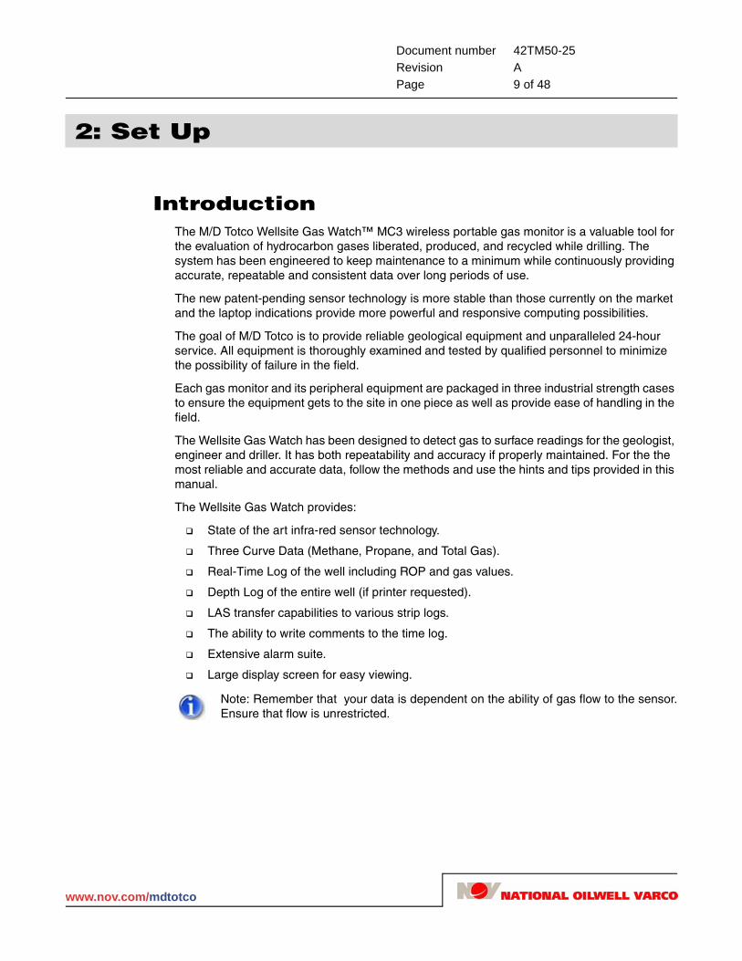
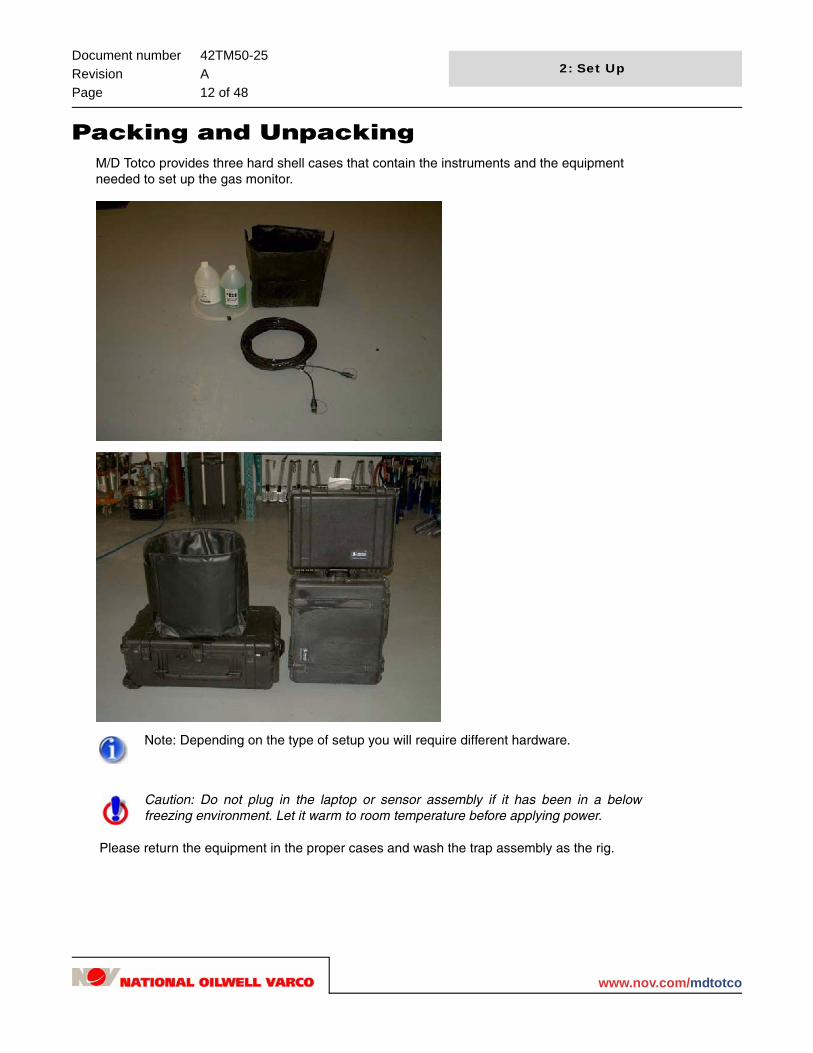
Packing and UnpackingM/D Totco provides three hard shell cases that contain the instruments and the equipment needed to set up the gas monitor.
Please return the equipment in the proper cases and wash the trap assembly as the rig.
Note: Depending on the type of setup you will require different hardware.
Caution: Do not plug in the laptop or sensor assembly if it has been in a below freezing environment. Let it warm to room temperature before applying power.
30
www.nov.com/mdtotco

Document number 42TM50-25Revision APage 13 of 48
2: Set Up
Case 1, Trap CaseContents of the trap case are:
1 – Gas Trap (Mud Agitator)
1 – Shaker Box Crank Bracket
1 – Glycol Assembly
4 – ½" plastic nuts for jar connection
1 – Rubber hose and cam lock
2 – Short ½" hose for jar connection
The trap case contains the gas trap, the T-stand, and the crank. The trap case is packed in a specific order. If this is not followed, the gear may not fit into the case.
1. Place the trap on the bottom and to the back of the case.
2. The crank is made as compact as possible and placed toward the front side of the case.
3. The T-stand is placed on top of the crank, tucking it in the case as low as possible.
Do not forget to include the rubber hose with camlocks, 2 1/2" x 12" poly-flow lines, and extra 1/2" plastic nuts for securing poly to T-stand.
4. Slowly close the case while watching for anything that does not fit properly, or may be pinched by closing the case.
If the case does not close properly, do not force it to close. Check all the parts and adjust them as necessary.
www.nov.com/mdtotco

Document number 42TM50-25Revision APage 14 of 48
2: Set Up
Case 2, Sensor CaseContents of the sensor case are:
1 – Accessory Kit
1 –Wireless Portable Gas Monitor
1 – Extension power cord
The sensor case contains the wireless gas monitor, the accessory kit, and the trap extension cord. The specific order for packing a sensor case is:
1. Place the trap extension cord in the bottom of the case. (As shown below).
2. Put the wireless unit on top of the trap extension cord.
The monitor antenna must face the front of the case, and the monitor must face up. This ensures the unit does not move around too much during shipping, and prevents the antenna from damage.
3. Finally, place the accessory kit in the case, on top of the other equipment. Close the case and set it aside while packing the laptop case.
30
www.nov.com/mdtotco

Document number 42TM50-25Revision APage 15 of 48
2: Set Up
Case 3, Laptop CaseThe contents of the laptop case do not need to be packed in any specific order.
Laptop and power supply
Manual
Serial laptop to interface box cable (9-pin male to 9-pin female)
Mouse and pad
Box of disks
Surge protector
Wireless radio (black box) with antenna and power adapter
WITS communication box (Pason or combo box)
USB to 9-pin serial cable
25 to 9-pin connector
Null Cable (9-pin female to 9-pin female, used for Pason or other)
www.nov.com/mdtotco

Document number 42TM50-25Revision APage 16 of 48
2: Set Up
Rig Up ProcedureWellsite Trailer
1. When arriving on site, place the laptop case in the shack and remove the equipment. Allow it to warm to room temperature if it has been in a below freezing environment.
2. Remove the laptop, surge protector, and wireless radio (black box) and set them on the work area.
3. Attach the wireless radio (black box) to the laptop (rear 9-pin COM port or USB to 9-pin labeled Sensor/Radio) using the 9-pin to 9-pin cable provided.
4. Screw in the antenna and plug in the power adapter for the wireless radio.
5. Screw in the 9-pin screws to ensure a good, tight connection.
6. Plug the mouse into the laptop.
7. Plug in the laptop computer to the surge protector, the laptop is equipped with its own back-up battery and power supply.
8. Plug the surge protector into a wall socket and turn on the power to the surge protector. Also, plug in any USB to 9-pin cables before turning on the laptop.
9. Turn on the laptop. The Wellsite Gas Watch program will start automatically.
30
www.nov.com/mdtotco

Document number 42TM50-25Revision APage 17 of 48
2: Set Up
RigTrap Set Up
1. Remove the trap assembly from trap case and hang it on the shaker box using the crank provided.
It is a good idea to inform the rig personnel about the trap level just in case they close or open the baffles on the shaker. It is also good practice to keep the trap at a consistent level throughout the well. Place the trap bracket and trap assembly such that when the rig is making a connection, the mud level will drop below the bottom of the trap canister by approximately 1/4" to 1/2". As the rig starts the mud pumps, the mud level will increase and the canister will become submerged to the appropriate level (approximately 2 to 3 inches). When the trap is installed correctly, the flow of the exit mud will be very brisk.
2. Be sure to place the trap in an area of high flow such as directly in front of a flow line. Do not put it in the corner of the shaker because there can be a build up of debris in this area which will plug the bottom of the trap and affect the gas readings.
3. Attach the glycol and dryer assembly (Figure 2.1 on page 18). Then slide the hose coupler onto the trap standpipe and lock it by pulling the handles up. Pour a small amount of glycol into the large bubble jar, about 2 inches. Do not over fill, you may
Caution: Do not lower the trap too deep or mud will be drawn through the line to the sensor assembly and a service call will be required.
www.nov.com/mdtotco

Document number 42TM50-25Revision APage 18 of 48
2: Set Up
suck up fluid. Prepare the calcium chloride dryer by pouring 2-3 inches of calcium chloride into the small jar. The glycol should bubble when the gas monitor is running and sucking the gas sample through.
Figure 2.1: Jar Set Up
Note: In winter conditions, it may be necessary to dilute the ethylene glycol with water (no less than a 60/40 mix) to keep it from freezing in the bubble jar.
30
www.nov.com/mdtotco

Document number 42TM50-25Revision APage 19 of 48
2: Set Up
Drying System1. The T-bar drying system consists of a long glycol jar and a short Ca Cl (calcium
chloride) jar. The lids are attached by eye hooks and swing freely. The jars contents are simply changed by unscrewing them from the lids. The jars are clearly labeled for content as well as height measurement. The whole system is light and portable. The hollow T-bar slides over the top of the mounting pin located on top of the gas trap making it convenient for maintenance.
2. The large inlet hose ascending from the standpipe, located on the canister, connects to the plastic inlet fitting on the glycol jar. On the other side of the glycol jar lid is a small compression fitting. From that fitting, a short piece of 3/8” poly needs to be in place to connect the compression fitting located on the Ca Cl jar lid. The last compression fitting on the Ca Cl jar is for the 1/4" poly-flow going to the gas monitor.
Note: For invert mud system, replace calcium with nylon batting.
Warning: Do not remove poly-flow line from T-stand before removing it from the trap.
www.nov.com/mdtotco

Document number 42TM50-25Revision APage 20 of 48
2: Set Up
3. Hang the Wellsite Gas Watch unit over the handrail of the mud tanks close to the trap. Make sure the switches are in the off position (right to left). Connect the left electrical NRL plug on the gas monitor to the trap power NRL plug.
4. Connect the extension power cord to the right NRL plug and run it to the utility shack or any available 115 VAC power plug.
5. Once the entire unit is connected, turn the breaker power on at the power source.
6. Turn the two toggle switches on at the bottom of the wireless detector. The LED light will light up through the glass window, and then the signal will lock onto the radio in the shack. The processor LED will blink and the TX (transmit) LED will flash twice each time the wireless sensor transmits (every 2 seconds).
7. Attach a coiled piece of poly-flow line to the small fitting on the side of the glycol jar (The other end will go to the Wellsite Gas Watch unit IN port on the top left hand side of the enclosure).
8. Insert poly line in the bottom of the in-line filter and use tie wraps (from the accessory kit) or tape to secure the poly in place.
Note: Be sure to use the in-line air filter.
30
www.nov.com/mdtotco

Document number 42TM50-25Revision APage 21 of 48
2: Set Up
Please read the helpful information section for more tips on the sampling system.
www.nov.com/mdtotco

Document number 42TM50-25Revision APage 22 of 48
2: Set Up
Wireless Gas Monitor Seasonal Operation
For winter operations, a winter hood is provided to help shield the unit from wind and snow as well as help to keep the unit clean. To install the hood, place the hood over top of the unit and secure the velcro flaps on each side of the hood.
The flap on the side of the gas monitor is to change the in-line filter. The flap on the front of the gas monitor is to view the LED plate.
30
www.nov.com/mdtotco

Document number 42TM50-25Revision APage 23 of 48
2: Set Up
LED PlateProcessor: Flashs quickly for the first minute while the unit is energizing. Once energized, the flash will be slow and steady. If the red LED stays solid, then shut down the sensor and turn it back on.
Sensor Packet: The sensor that transmits to the main board.
RX: Stays illuminated when it connects to the radio in the geologist shack. It will remain off when there is no connection.
TX: Illuminates when the WGM transmits from the main board to the radio in the geologist shack.
RSSI: Signal strength; full strength is indicated by full bars (3 LEDs illuminated), the LED will cycle until it can connect to the radio.
WITSWellsite Gas Watch is able to receive and transmit data through a well information transfer specifications (WITS) protocol. This protocol provides the necessary information to the computer for the operation of various electronic drilling recorders.
WITS supplies the depth, rop, and circulation indicators as well as on/off bottom indicators to the computer system.
Codes received are:
0108 – Bit depth
0110 – Hole depth
0113 – Rate of penetration
0123 – Pump 1
0124 – Pump 2
0125 – Pump 3
Off bottom is indicated by a bit depth of .5m less than the hole depth.
www.nov.com/mdtotco
Document number 42TM50-25Revision APage 24 of 48
2: Set Up
Codes sent are:
0139 – Lagged depth
0140 – Total gas
1212 – Methane
1214 – Propane
In order to receive WITS communication, a connection must be made to the drilling recorder. This is accomplished one of two ways:
1. Through a 6 ft. null modem cable (9-9 pin female to female) between the Wellsite Gas Watch laptop and the drilling recorder workstation in the shack.
2. Directly to the electronic drilling recorder at the tool pusher’s shack using the 250 ft. cable and the black communication interface box provided (the one with the Chimo/Other switch on the side not the radio).
Chimo, Pason, M/D Totco, Fleet Coil, and Ryan are some of the service companies currently sending and receiving WITS protocol.
M/D Totco – RigSense/Iris
Hardware:
(1) 9-pin female to 25-pin male adapter (located in the laptop case)
or
(1) Communication box and adapter
(1) Combination communication cable 250'
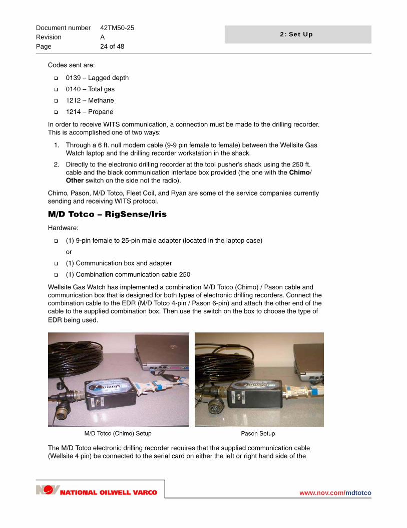
Wellsite Gas Watch has implemented a combination M/D Totco (Chimo) / Pason cable and communication box that is designed for both types of electronic drilling recorders. Connect the combination cable to the EDR (M/D Totco 4-pin / Pason 6-pin) and attach the other end of the cable to the supplied combination box. Then use the switch on the box to choose the type of EDR being used.
The M/D Totco electronic drilling recorder requires that the supplied communication cable (Wellsite 4 pin) be connected to the serial card on either the left or right hand side of the
M/D Totco (Chimo) Setup Pason Setup
30
www.nov.com/mdtotco

Document number 42TM50-25Revision APage 25 of 48
2: Set Up
Wellsite laptop using the 25-pin and 9-pin connectors and the cable provided. The M/D Totco system uses WITS protocol and will send the necessary drilling information to the gas monitor.
The depth is displayed automatically on the Wellsite program shortly after a new well is started and Start Log is selected from the File menu. The gas detector will display WITS ON.
If the hardware connection is made but a WITS signal is not recieved, the laptop displays WITS NO LINK.
For help with communication problems between Wellsite Gas Watch and RigSense (IRIS), refer to "Helpful Information" on page 44.
Interfacing to the Electronic Drilling Recorder
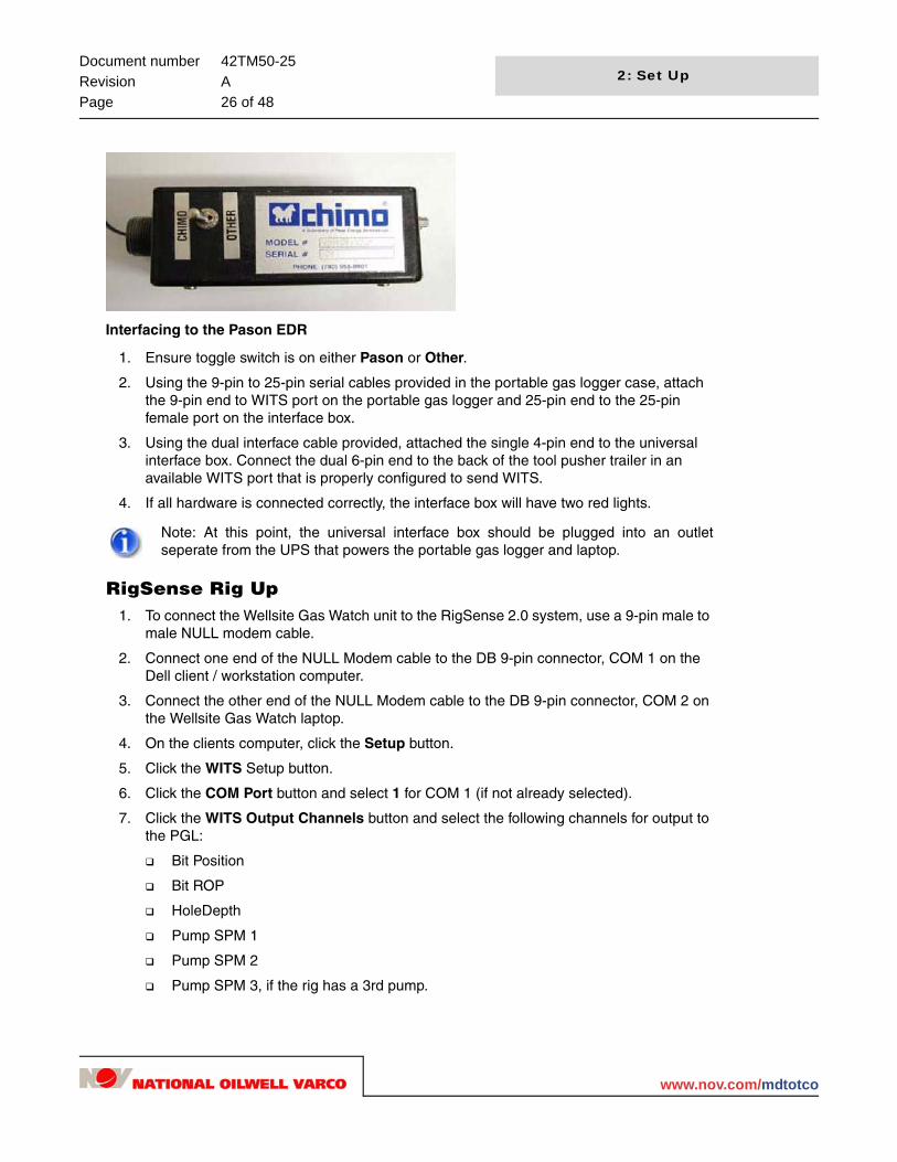
Interfacing to the M/D Totco (Chimo) EDR
1. Ensure toggle switch is on Chimo.
2. Using the 9-pin to 25-pin serial cables provided in the portable gas logger case, attach the 9-pin end to WITS port on the portable gas logger and 25-pin end to the 25-pin female port on the interface box.
3. Using the dual interface cable provided, attach the single 4-pin end to the universal interface box. Using the dual pigtail end, attach it to any available Chimo Workstation with a 4-pin Amphenol connector attached to COM 3.
4. If all hardware is good and is hooked in correctly, both lights in the interface box window will be illuminated red.
Note: At this point, the universal interface box should be plugged into an outlet seperate from the UPS that powers the portable gas logger and laptop.
www.nov.com/mdtotco
Document number 42TM50-25Revision APage 26 of 48
2: Set Up
Interfacing to the Pason EDR
1. Ensure toggle switch is on either Pason or Other.
2. Using the 9-pin to 25-pin serial cables provided in the portable gas logger case, attach the 9-pin end to WITS port on the portable gas logger and 25-pin end to the 25-pin female port on the interface box.
3. Using the dual interface cable provided, attached the single 4-pin end to the universal interface box. Connect the dual 6-pin end to the back of the tool pusher trailer in an available WITS port that is properly configured to send WITS.
4. If all hardware is connected correctly, the interface box will have two red lights.
RigSense Rig Up 1. To connect the Wellsite Gas Watch unit to the RigSense 2.0 system, use a 9-pin male to
male NULL modem cable.
2. Connect one end of the NULL Modem cable to the DB 9-pin connector, COM 1 on the Dell client / workstation computer.
3. Connect the other end of the NULL Modem cable to the DB 9-pin connector, COM 2 on the Wellsite Gas Watch laptop.
4. On the clients computer, click the Setup button.
5. Click the WITS Setup button.
6. Click the COM Port button and select 1 for COM 1 (if not already selected).
7. Click the WITS Output Channels button and select the following channels for output to the PGL:
Bit Position
Bit ROP
HoleDepth
Pump SPM 1
Pump SPM 2
Pump SPM 3, if the rig has a 3rd pump.
Note: At this point, the universal interface box should be plugged into an outlet seperate from the UPS that powers the portable gas logger and laptop.
30
www.nov.com/mdtotco

Document number 42TM50-25Revision APage 27 of 48
2: Set Up
8. Click the WITS Input Channels button and select the following channels for input to RigSense:
Lag Depth
Total Gas
Methane and propane gas (optional)
9. Click on the Exit button to leave the WITS Setup screen.
10. If a WITS signal is not being received on the Wellsite Gas Watch unit in about one minute, press the Alt & F4 keys on the RigSense 2.0 client. This will cause RigSense to shut down and automatically restart on the client computer. On to the Setup > WITS/Pulse > WITS Setup screen, the status displayed should show that WITS is Running.
11. If a WITS signal is still not being received on the Wellsite Gas Watch unit, reboot the Wellsite Gas Watch laptop.
12. If necessary reboot client.
13. If necessary restart RigSense on the AppSvr.
Setting Up Well InformationNow that the hardware and sample lines are installed, it is time to enter the well data and start logging the well.
If you have not yet done so:
1. Turn on the surge protector.
2. Turn on the laptop.
The laptop automatically opens the Wellsite Gas Watch program.
Note: The above input channels must be checked only on one RigSense client computer, the computer that is connected to the WellSite Gas Watch unit.
Note: the above two steps are not necessary if RigSEnse version 2.0, SP4 is installed.
www.nov.com/mdtotco
Document number 42TM50-25Revision APage 28 of 48
2: Set Up
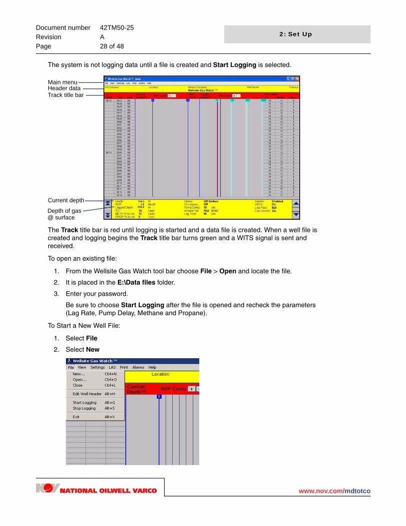
The system is not logging data until a file is created and Start Logging is selected.
The Track title bar is red until logging is started and a data file is created. When a well file is created and logging begins the Track title bar turns green and a WITS signal is sent and received.
To open an existing file:
1. From the Wellsite Gas Watch tool bar choose File > Open and locate the file.
2. It is placed in the E:\Data files folder.
3. Enter your password.
Be sure to choose Start Logging after the file is opened and recheck the parameters (Lag Rate, Pump Delay, Methane and Propane).
To Start a New Well File:
1. Select File
2. Select New
Depth of gas
Current depth
Main menu
Track title barHeader data
@ surface
30
www.nov.com/mdtotco
Document number 42TM50-25Revision APage 29 of 48
2: Set Up
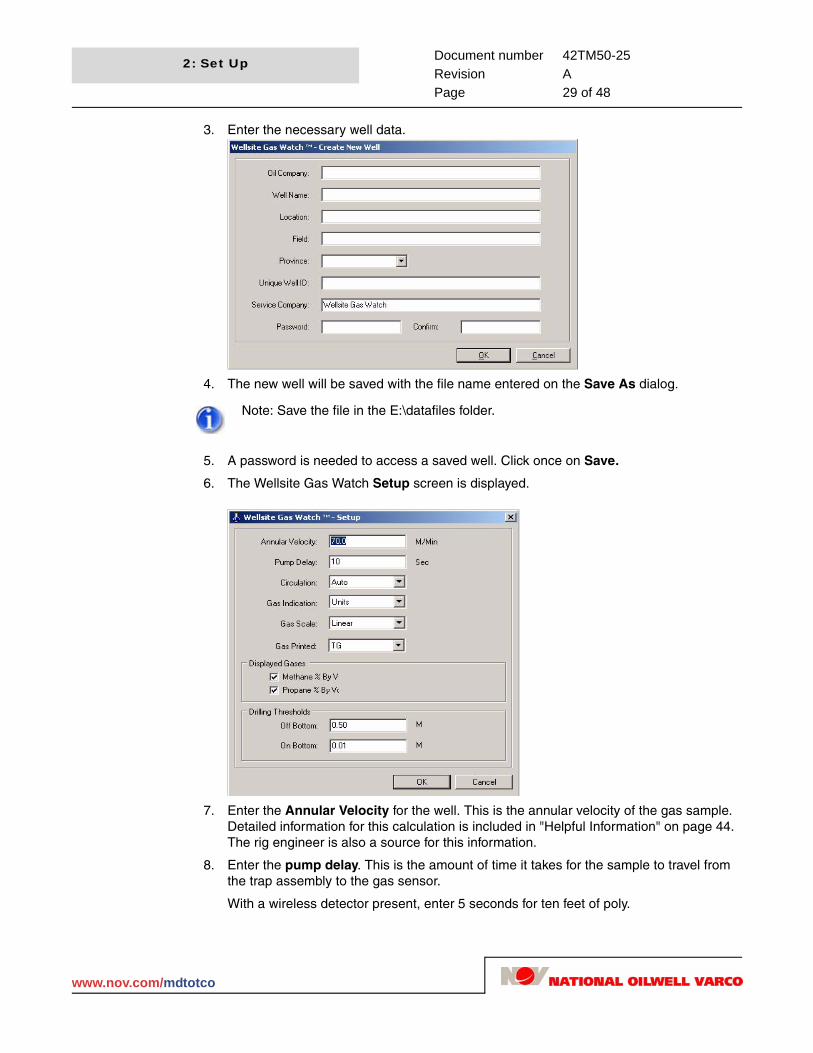
3. Enter the necessary well data.
4. The new well will be saved with the file name entered on the Save As dialog.
5. A password is needed to access a saved well. Click once on Save.
6. The Wellsite Gas Watch Setup screen is displayed.
7. Enter the Annular Velocity for the well. This is the annular velocity of the gas sample. Detailed information for this calculation is included in "Helpful Information" on page 44. The rig engineer is also a source for this information.
8. Enter the pump delay. This is the amount of time it takes for the sample to travel from the trap assembly to the gas sensor.
With a wireless detector present, enter 5 seconds for ten feet of poly.
Note: Save the file in the E:\datafiles folder.
www.nov.com/mdtotco
Document number 42TM50-25Revision APage 30 of 48
2: Set Up
9. The Circulation is determined by the presence of either a pump pressure switch (geolograph type setup) or the WITS signal supplied by other service companies. Auto is controlled automatically by the sensors on the rig. There is also a manual on and off setting for special situations where neither WITS nor pump pressure is available (i.e.: air drilling).
10. The Depth / WITS is used to indicate the depth on the gas monitor by way of either the depth encoder assembly or the WITS signal supplied by other service companies. If WITS is present, the depth will be displayed automatically after you choose Start Log from the File menu.
11. Enter the gas curve to print.
12. The Displayed Gases selection allows methane and propane gases to be displayed on the screen; TG is displayed by default.
13. Drilling Thresholds are the distances that define off bottom and on bottom while drilling. If you have a rig with tighter tolerances, the values can be changed here.
Note: Gas indication is units or percent; gas scale is linerar or arithmetic.
30
www.nov.com/mdtotco
Document number 42TM50-25Revision APage 31 of 48
3: Operation
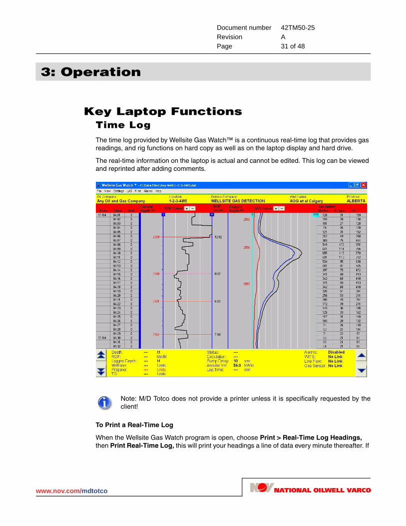
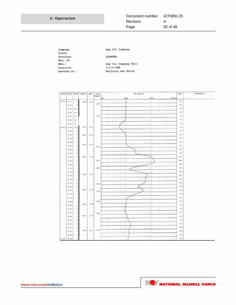
Key Laptop FunctionsTime LogThe time log provided by Wellsite Gas Watch™ is a continuous real-time log that provides gas readings, and rig functions on hard copy as well as on the laptop display and hard drive.
The real-time information on the laptop is actual and cannot be edited. This log can be viewed and reprinted after adding comments.
To Print a Real-Time Log
When the Wellsite Gas Watch program is open, choose Print > Real-Time Log Headings, then Print Real-Time Log, this will print your headings a line of data every minute thereafter. If
Note: M/D Totco does not provide a printer unless it is specifically requested by the client!
www.nov.com/mdtotco
Document number 42TM50-25Revision APage 32 of 48
3: Operation
it does not print, check all connections and make sure Real-time Log is checked under the print tab on the main tool bar.
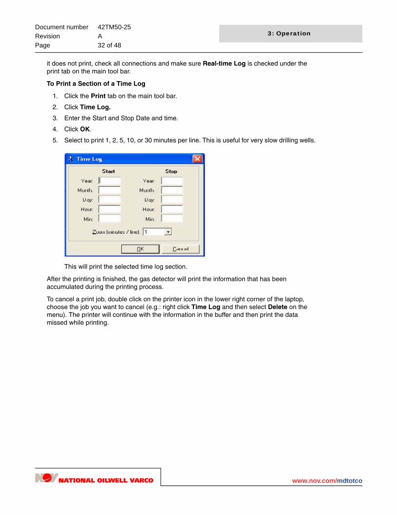
To Print a Section of a Time Log
1. Click the Print tab on the main tool bar.
2. Click Time Log.
3. Enter the Start and Stop Date and time.
4. Click OK.
5. Select to print 1, 2, 5, 10, or 30 minutes per line. This is useful for very slow drilling wells.
This will print the selected time log section.
After the printing is finished, the gas detector will print the information that has been accumulated during the printing process.
To cancel a print job, double click on the printer icon in the lower right corner of the laptop, choose the job you want to cancel (e.g.: right click Time Log and then select Delete on the menu). The printer will continue with the information in the buffer and then print the data missed while printing.
40
www.nov.com/mdtotco
Document number 42TM50-25Revision APage 33 of 48
3: Operation
www.nov.com/mdtotco

Document number 42TM50-25Revision APage 34 of 48
3: Operation
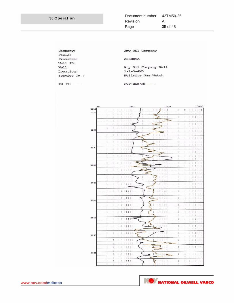
Depth LogThe Wellsite Gas Watch Depth Log provides a printout of depth with respect to the lagged gas values. If the lag rate was correct throughout the well, the higher gas values will correspond to the faster ROP zones. The effect of this will be a visual cross over of the ROP and gas. It is best to print this log in logarithmic scale, although linear is also available.
To print a depth log:
1. Click the Print tab on the main tool bar.
2. Select Depth Log.
3. Enter the Start and End Depths.
4. Select OK.
This will print the selected depth log.
To cancel a depth log print job:
1. Double click on the printer icon in the right hand corner of the computer screen.
2. Select a job listed.
3. Right click the selection and select delete on the pop-up menu.
After clearing the buffer, the printer will continue with the real-time data in the buffer while depth log was being printed.
40
www.nov.com/mdtotco
Document number 42TM50-25Revision APage 35 of 48
3: Operation
www.nov.com/mdtotco

Document number 42TM50-25Revision APage 36 of 48
3: Operation
LAS/ASCII File CreationASCII files are created to enable the portable gas detector information to be loaded into various strip logs that geologists use to present to their clients. The ASCII file is created by using the lagged gas information. This information may also be edited for import.
To create a LAS file and send it to floppy disk:
1. Go to the LAS tab on the main tool bar.
2. Choose Create LAS.
3. Enter the Start and Stop depth for the file.
4. Choose the depth step increments for the file. These are averaged values over the depth increments requested.
5. Choose whether to display data in percent or units.
6. Leave the Depth Correction and Scan to End of File checked. This feature will correct for depth changes that are made while drilling.
7. Select which gases to display in the LAS file.
8. Select OK.
Example 1: If the driller makes a forward depth correction, there is no data for that interval so null values will be displayed in the LAS file.
Example 2: If the driller makes a backward depth correction, the depth of 1,100m may be displayed twice. The data given in the LAS file is the last (most recent occurrence of 1,100m).
Example 3: If there is an erroneous depth (i.e. 20,000m) given over the LAS data interval requested, null values are displayed.
40
www.nov.com/mdtotco
Document number 42TM50-25Revision APage 37 of 48
3: Operation
Now that the LAS file has been created, it is available to import into the Strip Log program.
To view the LAS file you created on the Wellsite Gas Watch computer:
1. Click the Start icon in the bottom left of your laptop screen
2. Click Programs > Accessories > WordPad.
3. In WordPad click File > Open.
4. Select Look In A:\ (Floppy).
5. Under Files of Type: choose all documents and locate the ASCII file you had previously created.
6. Double click on the desired file to open it for viewing.
7. Edit the values in WordPad and save before strip log import.
AlarmsThe Wellsite Gas Watch has audible and visual alarms that can be set by the user. They are an excellent way to be alerted if there are problems on the rig or with the gas monitor so it is a good idea to use them.
To activate the alarms:
1. Enter the values for the alarms to set them.
2. Enable the alarms by selecting the appropriate alarm heading.
3. Select OK.
4. The alarms that are active will appear on the main real time screen at the bottom right.
5. Be sure to turn up the alarm volume on the laptop computer so the alarm is audible.
6. When an alarm sounds it must be acknowledged. Take corrective action on all alarms.
Note: The Wordpad file must be saved if edited.
www.nov.com/mdtotco

Document number 42TM50-25Revision APage 38 of 48
3: Operation
Communication alarms allow monitoring of the following:
WITS Informs when data from the EDR is not being received. This could mean the EDR is down or there is a connection problem to the EDR.
Link Informs when communication between the laptop radio and the wireless sensor has been lost.
Sensor Indicates sensor output has failed.
Line Flow Indicates line flow transducer output has failed.
40
www.nov.com/mdtotco

Document number 42TM50-25Revision APage 39 of 48
3: Operation
Shut DownWhen a well is completed, back-up the data files and then delete them from the laptop.
1. Back-up the data files and delete them from the laptop.
2. Close the Wellsite Gas Watch program.
3. Double click My computer on the desktop.
4. Navigate to E:\ Data Files and delete these files (.dat, .dpl, .raw).
5. Navigate to E:\ Morning Reports and delete these files.
6. Empty the files in the Recycle Bin on your desktop.
7. Remove any disks from the floppy drive.
8. GoTo Start (bottom left of desktop).
9. Click Shut Down.
10. Choose Shut down an click OK.
11. Pack the Wellsite Gas Watch in the cases as described in "Packing and Unpacking" on page 12.
www.nov.com/mdtotco

Document number 42TM50-25Revision APage 40 of 48
3: Operation
40
www.nov.com/mdtotco
Document number 42TM50-25Revision APage 41 of 48
4: Maintenance and Troubleshooting
Daily MaintenanceNow that the gas monitor has been set up, there are some daily maintenance procedures that must be followed in order to provide quality and consistent data.
TrapThe trap is a very important part of the gas detection system because it provides the sample to the detector. It is important to place the trap in a location of high turbulence, such as in front of the flow line in the shaker box. This will lessen the chance of shale build up under the trap and expose the beater bars to drilling mud gas that represents what is coming up hole.
Try to keep the trap at a consistent level in the shaker box. A change in trap level can affect the gas readings. Inform the rig crew not to close the baffles or increase the shaker level without notifying you. A submersed trap may cause fluid to be drawn into the flow line to the sensor; which will require a service call. It is important to check the dryer assembly and sample pipe in the plastic trap mold to ensure it is not plugged or frozen! Pouring hot water down the trap mold or using the wash gun at the rig can ensure there is an unobstructed gas sample getting to the gas detector.
During the winter, place the hood provided over the trap. This will keep the trap motor heat inside the sack, preventing the trap from freezing in extreme cold conditions. See "Wireless Gas Monitor Seasonal Operation" on page 22 for details.
If the trap is submerged it should not suck up fluid, but if laid down to clean the shale shaker the glycol will get sucked into the wireless unit. Please be careful to prevent a service call.
SensorThe gas sensor requires little maintenance to ensure there is a clean, dry gas flow. Ensure that there is no fluid reaching the sensor by properly maintaining the trap and dryer assembly.
Testing and use has shown that it is not necessary to zero the gas monitor. To check the zero, simply remove the incoming sample line to the wireless detector. It should come close to 20 units. A baseline set to zero and gas will be indicated on top of the zero baseline.
The integrity of the sensor can be tested by using the lighter provided from the accessory kit. First, release gas from the lighter into the gas in-line intake of the wireless detector (you must be logging to see a response). The response will vary depending on the condition and type of lighter used, but a response of 1-3% propane is acceptable for a 1-minute test.
It is a good idea to perform a gas test at the trap from time to time. Use the butane lighter provided to release the gas into the sample line at the calcium chloride dryer. Do not light the lighter at the shaker box, only release the butane gas at the sensor. Re-attach the sample
Note: Above all, do not allow fluid to be drawn into the sensor housing. If this happens call the local service representative.
www.nov.com/mdtotco

Document number 42TM50-25Revision APage 42 of 48
4: Maintenance and Troubleshooting
line and look at the log on the laptop or the real time print to see the lighter response. The response should be 1-3% propane for a one minute gas test.
Gas Sample LinesUse common sense when running the poly-flow and electrical lines across the mud tanks to ensure they do not get damaged by rig crew operations. Periodically check the flow lines for kinks, holes, and moisture. The flow lines are the conduits for proper gas readings.
TroubleshootingNo Depth or ROPWITS set-up: (If depth is not being picked up by the Wellsite Gas Watch™ laptop).
Check to see if the electronic drilling recorder is running properly.
Make sure you have chosen File > Start Logging on the Wellsite Gas Detection tool bar (green bar across the top).
Check the connections.
Visit the supplemental information at the back of this manual for individual electronic drilling recorder information.
Check to make sure that the combo box is plugged in.
Check to make sure the switch on the combo box is in the right place.
No Gas If you find you are not reading gas:
Do a butane test at the inline of the wireless portable gas monitor (be sure you are logging). The propane response should be 1-3% for a 60 second test.
Perform a butane test at the top of the calcium dryer. (DO NOT LIGHT the lighter at the shaker.) You will get a response on the laptop of 1-3% propane.
Check the trap assembly and make sure the gas sample can freely travel through the entire trap assembly. Run some water down the standpipe in the polyurethane mold to ensure good flow through the trap.
Check for a good seal in both the glycol and calcium chloride dryers. There should be an O-ring in each. If not, there is a spare in the accessory kit.
No FlowIf you find you have diminishing or no flow check the following:
Is the sensor box powered up?
Is the in-line air filter on the intake of the wireless gas monitor plugged up?
Is the airflow numeric indication over 900 on the laptop?
Note: M/D Totco recommends replacing the poly line every 30 days to reduce possibility of contamination.
48
www.nov.com/mdtotco
Document number 42TM50-25Revision APage 43 of 48
4: Maintenance and Troubleshooting
If you remove the sample in-line does the flow increase? If it does, there is an obstruction somewhere between the trap assembly and the gas monitor.
Check the trap assembly (AC power, dryer, standpipe, connections for obstructions).
Check the polyflow sample in line, (kinked, damaged, moisture, freezing).
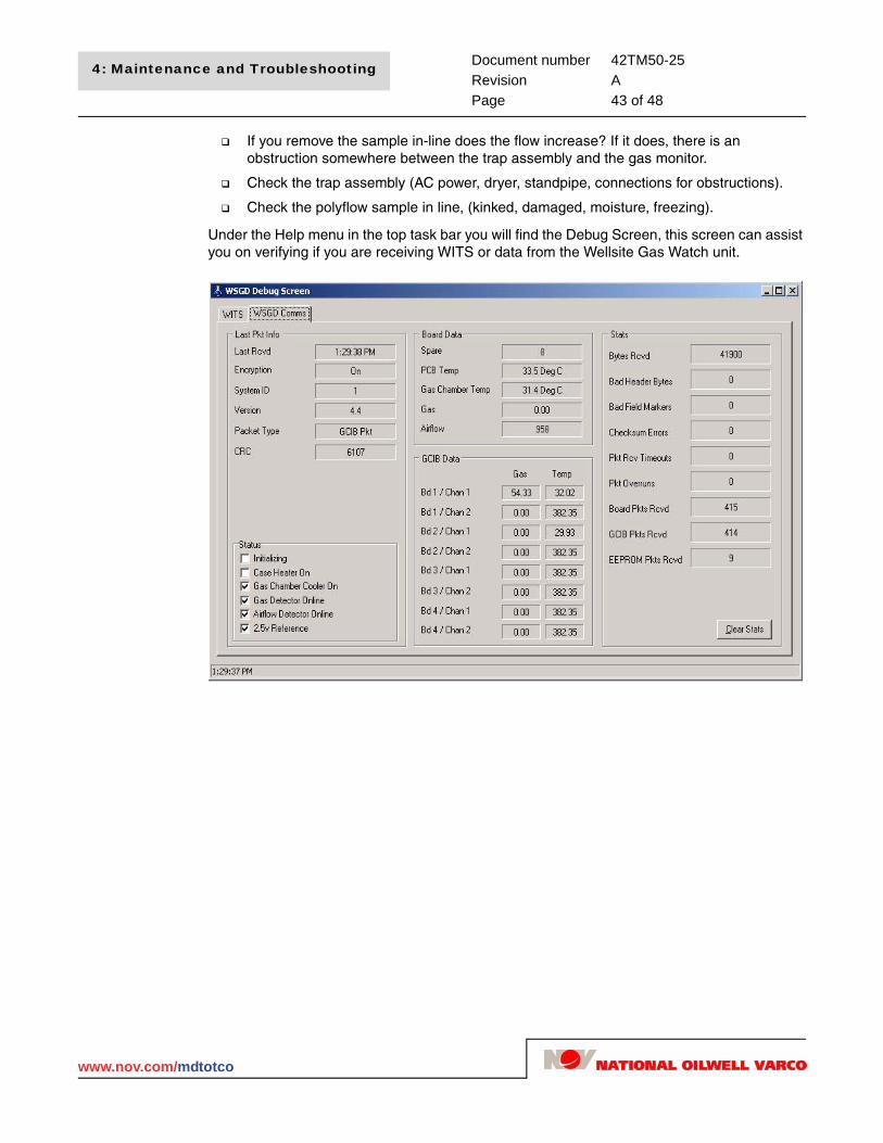
Under the Help menu in the top task bar you will find the Debug Screen, this screen can assist you on verifying if you are receiving WITS or data from the Wellsite Gas Watch unit.
www.nov.com/mdtotco
Document number 42TM50-25Revision APage 44 of 48
4: Maintenance and Troubleshooting
Helpful InformationLag Rate DeterminationThe Wellsite Gas Watch will take the lag rate you enter (annular velocity) and increase the amount of time of the gas to surface with increasing depth. If the pump strokes are increased or the pump output changes, the lag rate will also change. It is a good idea to test or make note of the lag rate frequently.
There are different methods that can be used to calculate the Lag Rate for a gas sample. We will attempt to explain a few of them:
1. Ask the engineer for the Annular Velocity. This will give you the correct value for the current depth of the well. Enter this into the lag rate in the Setup menu.
2. Wait for a coal marker and time the gas response to surface. This will allow you to calculate the lag time from the bit to surface.
Example: If you hit the coal when the bit is at 1800m and we see a gas response at the surface in 47min., the gas is traveling up the annulus at a rate of 1800m / 47min. = 38.3m / min.
* Enter this 38.3m / min. into the Lag Rate cell on the laptop Setup screen
3. Perform a tracer test (actual Lag Rate).
This test is the most reliable method to determine lag time. It is done by placing a tracer such as cut up flagging tape or whole oats in the drill pipe at the surface when the Kelly is broken off. The total time taken for the tracer to reach the surface, (shaker box) less the time to pump the tracer to the bit is the Lag time. From the lag time we can then calculate the rate.
M/D Totco NOV does not supply red dye pellets for tracer material.
Lag Rate (m / min.) = Depth / Time
The Lag Rate used for the Wellsite Gas Monitor is an annular velocity in m/min. that should be determined by a tracer type test.
After timing the tracer from the drill pipe to the shaker, we must calculate the time taken to pump the tracer down the drill pipe to the bit and subtract this from the total time. This is done by calculating the downtime or the time it takes for the mud to reach the bit from surface.
Note: Before putting anything down the well bore, ask the Engineer or Drillier if it is ok.
48
www.nov.com/mdtotco

Document number 42TM50-25Revision APage 45 of 48
4: Maintenance and Troubleshooting
4. Check mud report, quite often the lag rate will be indicated.
Example: It takes a total circulation time of 60 minutes for the tracer to show at the shaker from surface. The bit is currently at a depth of 1610m.
We need to know:
Downtime (min.) = pipe volume (m3 / m) / pump output (m
3 / min.)
Where pipe volume (m3) = pipe capacity (m
3/m) x length of pipe (m)
Pump output = m3 / stroke x 100 SPM = m3 / min.
Remember, the total pipe volumes will be the pipe volume + bottom hole assembly volume + any other piping that is in the drill string.
Say we know the total volume of the pipe is 10.33m3 and the pump output is 1.334m
3 /
min. Now:
When this value is put into the Wellsite Gas Watch unit, as the depth increases, the amount of time required for the gas to reach the surface will be increased due to increasing depth.
Where pump output (m3 / min.) = Liner size (mm) Table needed
Stroke Length (mm) Table needed
Strokes per minute Table needed
Downtime = 10.33m3
/ 1.334m3
/ min.= 7.74 minutes
Lag time at the current depth (1610m) = Total Time - Downtime
= 60 min. - 7.74 min. = 52.56 minTherefore the lag rate is 1610m / 52.56 min. = 30.63m / min.
www.nov.com/mdtotco

Document number 42TM50-25Revision APage 46 of 48
4: Maintenance and Troubleshooting
5. Calculate theoretical lag rate.
There are other formulas that can be used in order to theoretically calculate the Lag Rate (annular velocity). These calculations will not be accurate because of the hole washout etc. The best determination of lag rate is done with a tracer or marker.
Time = Depth / Annular Velocity
Annular Velocity =
Annular Velocity =
Pump output m3 / min. x 1273 x 103
(Hole diameter)2 - (Pipe diameter)2
Pump output m3 / min. x 1273 x 103
(Csg ID)2 - (Pipe OD)2
For casing use:
Annular Velocity =Pump output m3 / min. x 1273 x 103
(Hole OD)2 - (Pipe OD)2
Down Time =
Where:Pipe volume = pipe capacity x length of pipe
Pipe volume m3
Pump output m3 / min.
For drill pipe use:
48
www.nov.com/mdtotco

Document number 42TM50-25Revision APage 47 of 48
4: Maintenance and Troubleshooting
M/D Totco Drilling Recorder InformationA cable needs to be run from the M/D Totco computer, (usually tool pushes shack) to the portable gas monitor computer. The cable will come from the Com 3 port of the Server and change from a 25-pin DB connector to a 4-pin amphenol connector, (100ft. cable supplied by M/D Totco), then to the Wellsite Gas Monitor computer using the 25 to 9-pin connector provided by Wellsite and a pigtail with lights or a small black box.
If you are hooked up to a black WITS box, you will need to plug it in. The lights in the box will turn on. One light is for sending and the other is for receiving; the lights will flash when a signal passes through.
If you are hooked up to a pigtail with two rows of lights, once the RS232 is connected to the Wellsite Gas Watch Monitor, you should see some lights on the bar. The red #3 light blinking indicates that M/D Totco EDR is sending data, and the red #2 light blinking indicates that the gas monitor is sending data.
On the M/D Totco machine that is physically connected to the Wellsite Gas Watch Monitor, select close, then setup. Type in 955-8901 for a password select enter, then select the Sensors Installed button. ON THIS MACHINE ONLY: HAVE GEOLOGIST-MUDLOGGER and WITS (IN/OUT) CHECKED OFF. Now, select Update and choose Com 3 when asked for a com port and select Enter. Now, press the Select WITS Output button. The Wellsite Gas Watch Monitor requires Bit Depth, Hole Depth, P1, P2, and ROP. Select Update and then close to go back to the drilling recorder.
Total gas will be displayed at the top of the drilling recorder and the depth and ROP will be displayed on the gas monitor.
Chimo TroubleshootingQuestion:
Total gas shows up on the drilling recorder as square lines, and if I go back in time and then forward in time it changes. It may show the total gas dropping to zero and then coming back.
Answer:
Geologist - Mudlogger is checked off on more than one computer in sensors installed. Do not have it checked on any other machine other than the one it is connected to.
Question:
My gas monitor was getting depth and ROP but now it is not.
Answer:
Check the M/D Totco Electronic Drilling Recorder to ensure that it is working properly. If it is working alright then try restarting the Interface box of the logger. If this does not work, go to the M/D Totco EDR that the portable Wellsite Gas Watch unit is plugged into and press Alt-F4 until you are at a blue screen with white dots. Now click on the start button and then click on Model 3000 Drilling Recorder. It should re-initialize the Com port and start sending data again.
www.nov.com/mdtotco

Document number 42TM50-25Revision APage 48 of 48
4: Maintenance and Troubleshooting
48
www.nov.com/mdtotco