telpower - steven engineering
TRANSCRIPT
Overcurrent ProtectionSolutions
For The GlobalTelecommunications
Market
TELPOWER®

Worldwide Circuit Protection Solutions
The Right Choice For Telecommunications
Bussmann®
World’s leading supplier of fuses and fusible
protection systems is also the manufacturer of the
industry’s first truly global product line. Each
Bussmann product is backed by an efficient worldwide network of distribution,
customer service and technical support. • Today, Bussmann continues its 80-year
tradition of technological innovation by providing modern circuit
protection solutions to the telecommunications industry. Bussmann’s
dedicated Telpower® team provides consulting and technical exper-
tise to telecommunications clients. • The Bussmann product line
includes the most extensive circuit protection solutions approved for
use by a variety of major standards: U.L., CSA,
IEC, ISO…not to mention both European
(DIN, British Standard) and North
American style fuses for a wide range of
applications. Our manufacturing operations in the U.S., Denmark
and the United Kingdom have earned ISO 9000 certification,
assuring Bussmann customers the highest levels of quality across
every product line. • Knowledgeable. Responsive. Customer
focused. Bussmann continues to set the standard for circuit protec-
tion solutions in the global marketplace.
This catalog is intended to present product data and provide technical information that will help the end user with design application.Bussmann reserves the right, without notice, to change design or construction of any products and to discontinue or limit distributionof any products. Bussmann also reserves the right to change or update, without notice, any technical information contained in this catalog. Once a product has been selected, it should be tested by the user in all possible applications.
© 2001 Cooper Bussmann, Inc.Printed in U.S.A.
R
Bussmann®
i
Table of Contents
Telpower® DC Power Protection Systems PageFused Disconnect Switches and Fuses 1-13
Spare Fuseholders 14
Accessories 15
Indicating Fuses and Holders 16-17
Electronic – PC Board & Small Dimension FusesPC Board - Surface Mount 18-23
PC Board - Through Hole 24-26
⁄Ω¢∑ ≈ 1⁄Ω¢∑ Fuses 27-28
5mm ≈ 20mm Fuses 29-30
5mm ≈ 15mm Fuses 31
Telecommunications ProtectionTelpower® Specialty Fuses 32-33
Telpower Technology (T2) 34-38
BussmannInformation Fax ~636.527.1450
Now you can get current information about Bussmann Telpowerproducts at anytime, using BIF (Bussmann Information FAX) orvisit us on the World Wide Web.
BIF is a simple to use automated fax response system. All you need is a touch-tone telephone and a fax machine to get complete product specifications when you want it. BIF document numbers are located throughout this catalog. To get a detailed data sheet on the product of your choice, simplydial 636-527-1450 and request the document number listed. In a matter of minutes a data sheet will be faxed to you. It’s that simple.
BIF documents can also be downloaded from the Internet. TheBussmann web site is continuously updated with our newestproducts and latest data on circuit protection solutions. Visit usoften at http://www.bussmann.com
© 2001 Cooper Industries, Inc., Bussmann Division Printed in U.S.A.

CENTRAL OFFICE
AC
DC
BussmannPROTECTING THE LINES OF COMMUNICATION
SECONDARY
DISTRIBUTION
FRAME
PRIMARY
DISTRIBUTION
FRAME
OUTPUT
CIRCUIT
RECTIFIER
(AC to DC)
TRANSFORMER
(Single Phase)
BATTERY
UTILITY
30 AC
EMERGENCY
GENERATOR

NID/MTU
BURIED DISTRIBUTION
EQUIPMENT
EQUIPMENT
EQUIPMENT
SATELLITE
EARTH
STATION
MICROWAVE
RELAYSTATION
• PHONE
• FAX
• MODEM
• PBX


Bussmann®
1For complete specification data, visit our Web site at www.bussmann.comor call Bussmann Information Fax ~ 636.527.1450
Fused Disconnect Switch
Telpower® DC Power Protection Systems
BIF document: 5011
General Information:• Front access load and line connection standard—double
hole lug load connections 8 AWG wire.• Recognized branch circuit protection device.• Modular design—4 poles per module.• Ease of installation—Connection directly to bus bar.• Reduces external wiring—per pole.• LED alarm signaling (LED current 30mA max.).• Local and remote open-fuse indication.• Alarm test probe point, to allow on-site checking of alarm
circuitry.• Alarm output connection to .032” thick common alarm bus.• Bi-polar LED provides capability for both –48 Vdc
and +24 Vdc applications.• Fuse presence indication.• Fuse orientation rejection feature.• Totally enclosed module.• Spare fuseholders: Part No. 5TPH and TPSFH-AS (page 14)
TP159144 Pole Disconnect Switch and TPA Series FusesAmpere Rating: 50A per poleVoltage Rating: 145 VdcAgency Approvals:U.L. Recognized as a disconnect switch for interruption of
load current by means of withdrawing the fuse carrier.U.L. Recognized as a component for telecommunication
power distribution equipment (U.L. category QPQY2).U.L. Recognized fuses for branch circuit protection.CSA Component Acceptance for the system.
Material: U.L. rated 94V-0, 140°C rated
FuseFuse Type TPA TPA-BCurrent 3, 5, 10, 15, 20, 25, 30, 40, 50 20, 25Voltage 170 Vdc 65 VdcInterrupting 100 kA 20 kA
U.L. Recognized, Guide JFHR2, File E56412 (fuses), File E97649 (switch)CSA Certified, Class 1422-30, File 53787
Dimensional Data
mminches
TOP
Bussmann®Telpower® DC Power Protection Systems
Bussmann®
2 For complete specification data, visit our Web site at www.bussmann.comor call Bussmann Information Fax ~ 636.527.1450
Fused Disconnect Switch
Telpower® DC Power Protection Systems
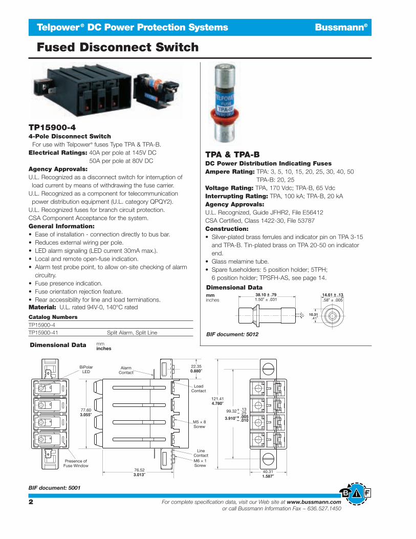
TP15900-44-Pole Disconnect Switch
For use with Telpower® fuses Type TPA & TPA-B.Electrical Ratings: 40A per pole at 145V DC
50A per pole at 80V DCAgency Approvals:U.L. Recognized as a disconnect switch for interruption ofload current by means of withdrawing the fuse carrier.
U.L. Recognized as a component for telecommunicationpower distribution equipment (U.L. category QPQY2).
U.L. Recognized fuses for branch circuit protection.CSA Component Acceptance for the system.General Information:• Ease of installation - connection directly to bus bar.• Reduces external wiring per pole.• LED alarm signaling (LED current 30mA max.).• Local and remote open-fuse indication.• Alarm test probe point, to allow on-site checking of alarm
circuitry.• Fuse presence indication.• Fuse orientation rejection feature.• Rear accessibility for line and load terminations.Material: U.L. rated 94V-0, 140°C rated
Dimensional Data
BIF document: 5001
mminches
Catalog NumbersTP15900-4TP15900-41 Split Alarm, Split Line
TPA & TPA-BDC Power Distribution Indicating FusesAmpere Rating: TPA: 3, 5, 10, 15, 20, 25, 30, 40, 50
TPA-B: 20, 25Voltage Rating: TPA, 170 Vdc; TPA-B, 65 VdcInterrupting Rating: TPA, 100 kA; TPA-B, 20 kAAgency Approvals:U.L. Recognized, Guide JFHR2, File E56412CSA Certified, Class 1422-30, File 53787Construction:• Silver-plated brass ferrules and indicator pin on TPA 3-15
and TPA-B. Tin-plated brass on TPA 20-50 on indicatorend.
• Glass melamine tube.• Spare fuseholders: 5 position holder; 5TPH;
6 position holder; TPSFH-AS, see page 14.
Dimensional Datamminches
BIF document: 5012

Bussmann®
3For complete specification data, visit our Web site at www.bussmann.comor call Bussmann Information Fax ~ 636.527.1450
Fused Disconnect Switch
Telpower® DC Power Protection Systems
BIF document: 5019
TP15900-4W4-Pole Disconnect Switch
For use with Telpower® fuses Type TPA & TPA-B.Screwless Terminals with Cage-Clamp Springs
licensed by “Wago”Electrical Rating: 40A per pole at 145V DC
50A per pole at 80V DCAgency Approvals:U.L. Recognized (Investigated to U.L. 1801) as a disconnect
switch for interruption of load current by means ofwithdrawing the fuse carrier.
U.L. Recognized as a component for telecommunicationpower distribution equipment (U.L. category QPQY2).
U.L. Recognized to meet the requirements for CanadianStandards.
General Information:• Ease of installation - connection directly to bus bar.• Reduces external wiring per pole.• LED alarm signaling (LED current 30mA max.).• Open fuse indication.• Alarm test probe point, to allow on-site checking of alarm
circuitry.• Fuse presence indication.• Fuse orientation rejection feature.• Rear accessibility for line and load terminations.• Screwless load terminals with cage-clamp springs licensed
by “Wago”.• Wire range—AWG (24-8).• No hardware required for load terminations.• Reduction of wiring time.Material: U.L. rated 94V-0, 140°C rated
Dimensional Data
Catalog NumbersTP15900-4W Wago clampTP15900-41W Wago clamp, split alarm, split line
mm(inches)

Bussmann®
4 For complete specification data, visit our Web site at www.bussmann.comor call Bussmann Information Fax ~ 636.527.1450
Fused Disconnect Switch
Telpower® DC Power Protection Systems
BIF document: 5002
15800Fused Disconnect SwitchAmpere Ratings: 3 to 70 AmperesVoltage Rating: 60 Volts DCAgency Approvals:U.L. Recognized, Guide QPQY2, File E97649
Catalog Numbers15800-R-200 Rear Access Panel Mounting
15800-F-200 Front Access Panel Mounting
General Information:• For use with the following fuses only:
Main: Telpower® TPS 3 to 70 Amp (page 5)Alarm: Bussmann GMT-A only (page 16).Recommend GMT-X Cover (page 16).
• Application Note: The line connection uses a ⁄Ω¢-20 bolt that threads into the line terminal. Theline terminal is designed with a float of ±.02 to
allow for variation in the distance between the
15800 mounting flange and the line bus bar
(see dimensional data). Equipment should be
designed to eliminate any relative movement
between the 15800 mounting flange and the
line bus bar.
• Alarm output with wire wrap terminal or connec-tion to .063” thick common alarm bus.
• Thermoplastic housing material U.L. rated94V-0, 150°C.
• Spare alarm and power fuse compartment.• Mounting hardware included.• Spare fuseholders:
for TPS fuses (TPSFH-AS);for GMT fuses (TPSFH-T), see page 14.
Dimensional Data15800-R-200
15800-F-200

Bussmann®
5For complete specification data, visit our Web site at www.bussmann.comor call Bussmann Information Fax ~ 636.527.1450
Telpower® Fuses, 1 to 70 Amps, 170 Volts DC
Telpower® DC Power Protection Systems
BIF document: 5009
General Information:• TELPOWER® fuses bring modern power fuse design to the
telecommunications industry.• TELPOWER® fuse line is the first to be specifically designed
to meet the unique needs of DC Power DistributionSystems.
• The U.L. Recognized ratings of 170 Volts DC and 100,000Amps interrupting rating along with the fuse’s current-limiting capability make this fuse ideal for overcurrent protection on existing DC Distribution Systems.
• A unique BLUE label is used on all TELPOWER® fuses todesignate their DC capability.
• Circuit board applications available.• Silver-plated brass ferrules.• Glass melamine tube.• For use with Bussmann Fused Disconnect Switch 15800.• Spare Fuseholder: TPSFH-AS (see page 14)
TPSDC Power Distribution FusesAmpere Rating: 1 to 70 AmperesVoltage Rating: 170 Volts DCInterrupting Rating: 100,000AAgency Approvals:U.L. Recognized, File E56412, Guide JFHR2 Catalog NumbersTPS-1 TPS-6L TPS-30 TPS-50VTPS-1L TPS-10 TPS-30L TPS-60TPS-2 TPS-10L TPS-35 TPS-60LTPS-2L TPS-15 TPS-35L TPS-70TPS-3 TPS-15L TPS-40 TPS-70LTPS-3L TPS-20 TPS-40L TPS-70LBTPS-5 TPS-20L TPS-40V —TPS-5L TPS-25 TPS-50 —TPS-6 TPS-25L TPS-50L —
Dimensional DataTPS-(AMP)
Custom Designs• Printed circuit board variations available.
TPS-(AMP)L
TPS-(AMP)V
TPS-(AMP)LB

Bussmann®
6 For complete specification data, visit our Web site at www.bussmann.comor call Bussmann Information Fax ~ 636.527.1450
Fused Disconnect Switch
Telpower® DC Power Protection Systems
Fused Disconnect Switches
15100Fused Disconnect System
For use with Telpower® Fuses Type TPL.Ampere Ratings: 70 to 600 AmperesVoltage Rating: 60 Volts DCU.L. Withstand Rating: 100,000AAgency Approvals:U.L. Recognized, File E97649
Catalog Numbers15100-401 For use with TPL series fuses 70 to 400 Amp15100-602 For use with TPL series fuses 300 to 600 Amp15100-605 For use with TPL series fuses 300 to 600 Amp
(Short Studs)
BIF document: 5003
Dimensional Data15100-401
Note: 605 supplied with 4 nuts only.
7For complete specification data, visit our Web site at www.bussmann.comor call Bussmann Information Fax ~ 636.527.1450
Bussmann®
Fused Disconnect Switch
Telpower® DC Power Protection Systems
BIF document: 5004
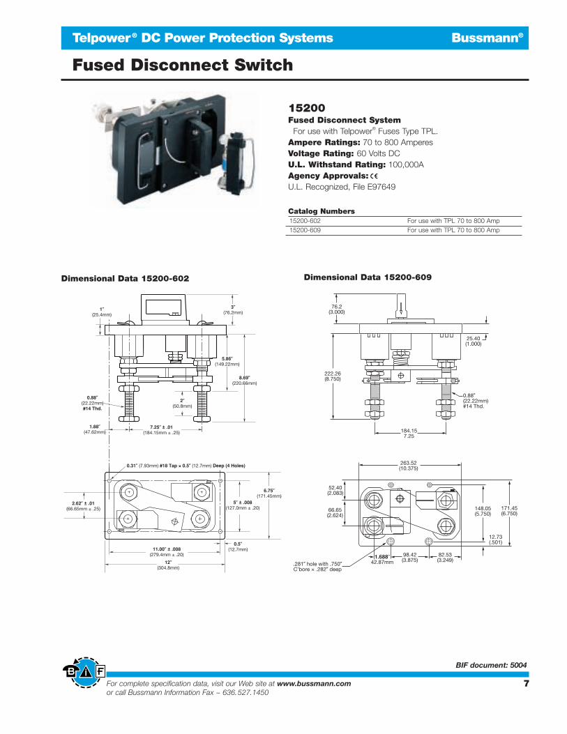
15200Fused Disconnect System
For use with Telpower® Fuses Type TPL.Ampere Ratings: 70 to 800 AmperesVoltage Rating: 60 Volts DCU.L. Withstand Rating: 100,000AAgency Approvals:U.L. Recognized, File E97649
Catalog Numbers15200-602 For use with TPL 70 to 800 Amp15200-609 For use with TPL 70 to 800 Amp
Dimensional Data 15200-602
Dimensional Data 15200-609

Bussmann®
8 For complete specification data, visit our Web site at www.bussmann.comor call Bussmann Information Fax ~ 636.527.1450
Telpower® High Current Switch TPHCS
Telpower® DC Power Protection Systems
BIF document: 5020
TPHCSTelpower® High Current SwitchFor use with Telpower® Fuses Type TPL-B AND TPL-C.Ampere Ratings: 70 to 800 AmperesVoltage Rating: 80 Volts DCU.L. Withstand Rating: 100,000AAgency Information:U.L. Recognized (investigated to U.L. 1801) as a disconnect switch for the interruption of load current by means of withdrawing the fuse carrier.U.L. Recognized to meet the requirements forCanadian Standards.
General Information:• Innovative new design eliminates need for tools to
replace the Telpower® type TPL-B or TPL-C fuse.• Easy to install–captive fasteners allow for direct
busbar mounting (bolts not included).• Optional new electronic alarm provides both local
and remote open-fuse indications.—Bipolar alarm designed for both Central Office and
Radio applications.—Local LED alarm indication for ease-of-viewing.—Standard ⁄Ω¢∑ male quick-connect terminal for
effortless remote alarm connection (Maximumremote alarm current: 20mA).
—Eliminates need for parallel indicating fuses.• Fuse presence window allows for easy viewing of
installed fuse ampere rating.• Compact design for today’s high power, high-density
cabinets.• Available as complete switch or pullout and base
may be purchased separately.
Catalog Numbers-Switches (Pullout and Base) Series Fuse Ampere RatingTPHCS250-M High Current Switch, Metric TPL-B 70 to 250 AmpTPHCS250-E High Current Switch, English TPL-B 70 to 250 AmpTPHCS250-ML High Current Switch, Metric, LED TPL-B 70 to 250 AmpTPHCS250-EL High Current Switch, English, LED TPL-B 70 to 250 Amp TPHCS250-MAV High Current Switch, Metric, Alarm TPL-B 70 to 250 AmpTPHCS250-EAV High Current Switch, English, Alarm TPL-B 70 to 250 AmpTPHCS800-M High Current Switch, Metric TPL-C 300 to 800 AmpTPHCS800-E High Current Switch, English TPL-C 300 to 800 AmpTPHCS800-ML High Current Switch, Metric, LED TPL-C 300 to 800 AmpTPHCS800-EL High Current Switch, English, LED TPL-C 300 to 800 AmpTPHCS800-MAV High Current Switch, Metric, Alarm TPL-C 300 to 800 Amp TPHCS800-EAV High Current Switch, English, Alarm TPL-C 300 to 800 Amp
Catalog Numbers – Components Series Fuse Ampere RatingTPHCS250-P Pullout only – 250 A TPL-B 70 to 250 AmpTPHCS800-P Pullout only – 800 A TPL-C 300 to 800 AmpTPHCS-B-M Base only, Metric — 800 Amp Max.TPHCS-B-E Base only, English — 800 Amp Max.TPHCS-B-ML Base only, Metric, LED — 800 Amp Max.TPHCS-B-EL Base only, English, LED — 800 Amp Max.TPHCS-B-MAV Base only, Metric, Alarm — 800 Amp Max.TPHCS-B-EAV Base only, English, Alarm — 800 Amp Max.
Part Number System–Switches (Pullout and Base)To identify part number, replace block with appropriate suffix to identify amperage, thread type, and alarm option.
Thread (select one)M - Metric, M8 x 1.25E - English, 5/16 - 18Alarm (leave blank for non-alarming version) L - LED Only, Requires Input From Customer Alarm CircuitAV - Alarm, System Voltage
TPHCS –
TPHCS – B –
*
*
*Consult factory for availability
Amperage (select one)250 - For Use With 70 to 250
Amp Type TPL-B Fuses800 - For Use With 300 to 800
Amp Type TPL-C Fuses
Thread (select one) M - Metric, M8 x 1.25E - English, 5/16 - 18
Alarm (leave blank for non-alarming version) L - LED Only, Requires Input From Customer Alarm CircuitAV - Alarm, System Voltage
Part Number System–BasesTo identify part number, replace block with appropriatesuffix to identify thread type, and alarm option.
*Consult factory for availability
TPHCS800-MAV (shown)

Bussmann®
9For complete specification data, visit our Web site at www.bussmann.comor call Bussmann Information Fax ~ 636.527.1450
Telpower® DC Power Protection Systems
BIF document: 5020
TPHCS –M & –E TPHCS-Dimensional Data
TPHCS COMPONENTSSee Catalog Numbers for complete list
TPHCS –ML & –EL
TPHCS800-P TPHCS250-P
TPHCS-B-M (shown for reference)
mm(in)
LED alarm connections ⁄Ω¢∑ male quick connects.
Quick-connect terminals
LED CIRCUIT SCHEMATIC
BOTTOM VIEW
PULLOUTS
BASES
LED open-fuseindication
when usedwith customer
provided alarmcircuit
NOTE:1.TPHCS –Mand –E are thesame with theexception ofthread type.
NOTES: 1. TPHCS –ML & –EL are the same with the exception of thread type.
2. Maximum continuous LED current 20mA.
NOTES:1. TPHCS250 and
TPHCS800pullouts and bases are the same with exception to the type of fuse, TPL-B or TPL-C, the pullout will carry.
2. Plastic rated UL94V-0, 140°C RTI.
4700 Ω
22.2(0.88)
41.02(1.615)
Ø 7.62(0.300)Typ. 4
12.7(0.50)
74.6(2.94)
25.9(1.02)
122.43(4.820)8.8
(0.34)
See table for partnumber format
100.5 REF(3.96)
66.4(2.62)
105.2(4.14)
Threaded Insert, 4 PlacesM8x1.25 (-M Series) 5/16-18 (-E Series)Recommended Torque 15N • m (11 Ft-lb)
Tin Plated CopperTerminals
139.7(5.50)
24.8 REF(0.98)
39.2 REF(1.54)
16.76(0.660)
13.2(0.52)
17.3(0.68)
61.47(2.420)
Telpower® High Current Switch TPHCS

General Information:• High amp version of Bussmann 15800 series
Fused Disconnect Switch.• Similar profile, mounting method, and backplane
configuration as 15800 Series. The TP158HCcan be installed into existing 15800 Series panelsusing the space of two 15800 disconnects.
• Innovative new fuse pullout design eliminatesneed for tools to replace the Telpower® typeTPL-B fuse.
• For use with the following fuses only:Main: Telpower® TPL-B 70-250 Amperes.Alarm: Bussmann GMT-A only.
• Alarm output with wire wrap terminal or connection to .063” thick common alarm bus.
• Hardware included:Load: washer, split lockwasher, and 5/16 _ 18 nut.
• Thermoplastic housing material U.L. rated 94V-0, 150°C.• Spare fuseholders:
for TPL-B fuses (TPSFH-LB), see page 14;for GMT fuses (TPSFH-T), see page 14.
• Application Note: The line connection uses a 1/4-20 bolt(metric – M6X1) that threads into the line terminal. The lineterminal is designed with a float of ±.02 in. (± .50mm) toallow for variation in the distance between the TP158HCmounting flange and the line bus bar (see dimensionaldata). Equipment should be designed to eliminate any rel-ative movement between the TP158HC mounting flangeand the line bus bar.
• Application Note: The alarm circuit is not intended for precharging of capacitive circuits. Alarm circuit current1 Ampere maximum.
Bussmann®
Fused Disconnect Switch
TP158HCFused Disconnect SwitchFor use with Telpower® Fuses Type TPL-B.Ampere Ratings: 70-250 AmperesVoltage Rating: 80 Volts DCU.L. Withstand Rating: 100,000AAgency Information:U.L. Recognized (investigated to U.L. 1801) as adisconnect switch for the interruption of load currentby means of withdrawing the fuse pullout.Guide QPQY2, File E97649.Catalog Numbers:TP158HC: Rear Access, Panel Mounting, EnglishTP158HC: Rear Access, Panel Mounting, Metric
TP158HC
Telpower® DC Power Protection Systems
Easy Fuse Replacement
10 For complete specification data, visit our Web site at www.bussmann.comor call Bussmann Information Fax ~ 636.527.1450
BIF document: 5021

Bussmann®
Fused Disconnect Switch TP158HC
Telpower® DC Power Protection Systems
TP
158HC
- Dim
ensio
nal D
ata
11For complete specification data, visit our Web site at www.bussmann.comor call Bussmann Information Fax ~ 636.527.1450
BIF document:5021

Bussmann®
12 For complete specification data, visit our Web site at www.bussmann.comor call Bussmann Information Fax ~ 636.527.1450
Telpower® DC Power Protection Systems
BIF document: 5005
Telpower® Fuses, 70 to 800 Amps, 170 Volts DC
TPLDC Power Distribution FusesAmpere Ratings: 70 to 800 AmperesVoltage Rating: 170 Volts DCCurrent-LimitingInterrupting Rating: 100,000AConstruction: Silver-Plated TerminalsAgency Approvals:U.L. Recognized, Guide JFHR2, File E56412Bellcore
Ordering Information:TPL Telpower® (170 Volts DC)
Catalog Ampere Carton Weight*
Number Rating Qty. Lbs. Kg.
TPL-BA 70 5 1.6 0.73
TPL-BB 80 5 1.6 0.73
TPL-BC 90 5 1.6 0.73
TPL-BD 100 5 1.6 0.73
TPL-BE 125 5 1.6 0.73
TPL-BF 150 5 1.6 0.73
TPL-BG 175 5 1.6 0.73
TPL-BH 200 5 1.6 0.73
TPL-BK 225 5 1.6 0.73
TPL-BL 250 5 1.6 0.73
TPL-CN 300 1 0.9 0.4
TPL-CO 350 1 0.9 0.4
TPL-CR 400 1 0.9 0.4
TPL-CU 450 1 0.9 0.4
TPL-CV 500 1 0.9 0.4
TPL-CZ 600 1 0.9 0.4
TPL-CZH 800 1 0.9 0.4
*Weight per carton.
General Information:• Designed for DC power distribution systems.• Recognized branch circuit protection.• Current-limiting capability.• Complete system coordination capability.• Energy savings with low watts loss, low operating tempera-
tures, and minimum I2t levels.• Use with Telpower® 15100, 15200, TP158HC and TPHCS
disconnect systems.• For replacement of Bussmann’s UBO fuses a TPL-TA
adaptor kit is necessary.• Spare fuseholders:
TPSFH-LB (for TPL-B fuses)TPSFH-LC (for TPL-C fuses), see page 14.
Dimensional Data

Bussmann®
13For complete specification data, visit our Web site at www.bussmann.comor call Bussmann Information Fax ~ 636.527.1450
Telpower® DC Power Protection Systems
BIF document: 5006
TPNCurrent-LimitingDC Power Distribution FusesAmpere Ratings: 1 to 600 AmperesVoltage Rating: 170 Volts DCInterrupting Rating: 100,000AConstruction: Silver-Plated TerminalsAgency Approvals:U.L. Recognized, Guide JFHR2, File E56412
Catalog NumbersTPN-1 TPN-45 TPN-200
TPN-3 TPN-50 TPN-225
TPN-5 TPN-60 TPN-250
TPN-6 TPN-70 TPN-300
TPN-10 TPN-80 TPN-350
TPN-15 TPN-90 TPN-400
TPN-20 TPN-100 TPN-450
TPN-25 TPN-110 TPN-500
TPN-30 TPN-125 TPN-600
TPN-35 TPN-150 —
TPN-40 TPN-175 —
Carton Quantity and Weight TPN Telpower® (170 Volts DC)
Catalog Carton Weight*
Number Qty. Lbs. Kg.
1-30 10 0.45 0.204
35-60 10 1.82 0.824
70-100 5 1.85 0.838
110-200 1 1.05 0.476
225-400 1 2.38 1.078
450-600 1 3.50 1.587
*Weight per carton.
General Information:• Designed for DC power distribution systems.• The TPN series of fuses are dimensionally similar to Class R
fuses.• Recognized branch circuit protection.• Current-limiting capability.
Recommended Class R FuseblocksCatalog
Amps Poles Number
1 R25030-1CR
1 to 30 2 R25030-2CR
3 R25030-3CR
1 R25060-1CR
35 to 60 2 R25060-2CR
3 R25060-3CR
1 R25100-1CR
70 to 100 2 R25100-2CR
3 R25100-3CR
110 to 2001 R25200-1CR
3 R25200-3CR
225 to 400 1 R25400-1CR
450 to 600 1 R25600-1CR
Dimensional Data
• Complete system coordination capability.• Energy savings with low watts loss, low operating tempera-
tures, and minimum I2t levels.• Spare fuseholders:
TPSFH-N30 (for TPN 1-30)TPSFH-N60 (for TPN 35-60), see page 14.
Telpower® Fuses, 1-600 Amps, 170 Volts DC

Bussmann®
14 For complete specification data, visit our Web site at www.bussmann.comor call Bussmann Information Fax ~ 636.527.1450
Telpower® DC Power Protection Systems
Spare Fuseholders
Spare Fuseholders• Durable construction using black thermoplastic with
U.L. 94V-0 flammability rating.• Common mounting (.16 dia. hole) using #6 screws or bolts
on 5-inch centers.• Dovetailed interlocking between fuseholders simplifies
installation and reduces needed hardware.• Common footprint allows for any combination of
fuseholders to be mounted together.• Built-in retaining clips secure fuses.
CatalogNumbers CapacityTPSFH-T 10-position For use with GMT fuses
TPSFH-AS 6-position For use with TPA & TPS fuses
TPSFH-N30 4-position For use with TPN (1-30 Amp) fuses
TPSFH-N60 1-position For use with TPN (35-60 Amp) fuses
TPSFH-LB 1-position For use with TPL-B series fuses
TPSFH-LC 1-position For use with TPL-C series fuses
TPSFH-70 12-position For use with Series 70 fuses
Common Prefix TPSFH-
T
AS
N30
N60
LB
LC
70
inchesmm

Bussmann®
15For complete specification data, visit our Web site at www.bussmann.comor call Bussmann Information Fax ~ 636.527.1450
Telpower® DC Power Protection Systems
Accessories
FusepullersCat. Carton Weight
No. Application Qty. Lbs. Kg.
FP-2 ⁄‹Ω£™ to ⁄‹Ω¡§ dia. fuses 10 1.25 .57
FP-3 1 to 1‹Ω¢ dia. fuses 10 1.73 .78
FP-4 1‹Ω¢ to 2⁄Ω™ dia. fuses 1 0.53 .24
FP-6 0-60A T-Tron fuses 1 0.008 .004
FP-A3 Glass Tube & ATC fuses 10 0.08 .04
630 European Fuses 1 .59 .27
FT-2Fuse Tester24 Volt Maximum• Test automotive, glass tube and ferrule fuses up to 1‡Ω•
length.• Batteries are included.WARNING: DO NOT test electrical fuses in the fuse panel.
FP-4 FP-A3 630FP-6FP-3 FP-2

Bussmann®
16 For complete specification data, visit our Web site at www.bussmann.comor call Bussmann Information Fax ~ 636.527.1450
Telpower® DC Power Protection Systems
BIF document: 5008 BIF document: 5010
Indicating Fuses & Holders
GMT Fast-Acting FusesVoltage Rating: 60 Vdc; 125 VacInterrupting Rating: 450 Amps, 60 Volt DC;300 Amps, 125 Volt AC/Volt DC
Agency Approvals:U.L. Recognized, Guide JFHR2, File E56412Materials:
Body: Thermoplastic, U.L. 94V-0 flammability ratingTerminals: Tin-plated beryllium copper
Carton Qty. and Weight: 100 Fuses per carton;0.33 lbs. (150g)
Fuseholders: Catalog No. HLT, HLS, and PCTSpare Fuseholder: TPSFH-T (see page 14).
Catalog NumbersCatalog Color Catalog ColorSymbol Code Symbol Code
GMT-⁄°Ω¡ººA Yellow GMT-3A Blue
GMT-⁄Ω¢A Violet GMT-3⁄Ω™A White/Blue
GMT-‹Ω•A White/Gray GMT-4A White/Brown
GMT-⁄Ω™A Red GMT-5A Green
GMT-flfiΩ¡ººA Black GMT-7⁄Ω™A Black/White
GMT-‹Ω¢A Brown GMT-10A Red/White
GMT-1A Gray GMT-12A Yellow/Green
GMT-1⁄Ω£A White GMT-15A Red/Blue
GMT-1⁄Ω™A White/Yellow GMT-Dummy Gray Body
GMT-2A Orange GMT-X Clear Cover
Some GMT sizes may be sold in bulk pack only.
GMT-A•The GMT-A is designed specifically for use in the Telpower®
series 15800 Fused Disconnect Switch (page 4).• The GMT-A has the same ratings and agency approvalsas the standard GMT fuses as shown above.
HLS, HLT, PCTFuseholders for GMT Type Indicating FusesVoltage Rating: 60 Vdc; 125 Vac Agency Approvals:U.L. Recognized, Guide IZLT2, Fille E14853, 15 Amps (60 Vdc)Materials:Body: Thermoplastic, U.L. 94V-0 flammability ratingTerminals: Tin-plated copper
GMT - Dummy GMT - A (Alarm)
GMT-X
Catalog Symbol Color CodeGMT-A Yellow

Bussmann®
17For complete specification data, visit our Web site at www.bussmann.comor call Bussmann Information Fax ~ 636.527.1450
Telpower® DC Power Protection Systems
BIF document: 5007 BIF document: 5007
Indicating Fuse & Holder
70 SeriesIndicating Type FuseVoltage Rating: 125 Volts AC; 300 Volts DCAgency Approvals:U.L. Recognized, Guide JDYX2, File E19180Bellcore
70 Series Telpower® (125 Volts AC, 300 Volts DC)Lucent
Catalog Ampere Voltage Rating Color Comcode Code/Number Rating AC DC Code Ref. No. List No.
70P-⁄Ω¡ºA* ⁄Ω¡º 125V 300V Gray/Wh 100203413 KS23751-L10
70R-⁄fiΩ¡ººA* ⁄fiΩ¡ºº 125V 300V Red/Wh 101384550 KS23751-L11
70E-⁄°Ω¡ººA* ⁄°Ω¡ºº 125V 300V Yellow 100203363 KS23751-L5
70X-¤Ω¡ºA ¤Ω¡º 125V 300V Black — —
70F-⁄Ω¢A* ⁄Ω¢ 125V 300V Violet 100203371 KS23751-L6
70K-⁄Ω¢A* ⁄Ω¢ 125V 300V Violet/Wh 100203405 KS23751-L9
70G-⁄Ω™A* ⁄Ω™ 125V 300V Red 100203389 KS23751-L7
70H-‹Ω¢A* ‹Ω¢ 125V 300V Brown 100203397 KS23751-L8
70I-1A 1 125V 300V Pink — —
70A-1⁄Ω£A* 1⁄Ω£ 125V 300V White 100203322 KS23751-L1
70B-2A* 2 125V 300V Orange 100203330 KS23751-L2
70C-3A* 3 125V 300V Blue 100203348 KS23751-L3
70J-3⁄Ω™A 3⁄Ω™ 125V 300V Black/Wh — —
70D-5A* 5 125V 300V Grn/Blk 100203355 KS23751-L4
70L-6A 6 125V 300V Grn/Wh — —
70M-8A 8 125V 300V Brown/Wh — —
70N-10A 10 125V 300V Violet/Yel — —
GKB-10A 10 125V 300V Violet/Yel — —
72A Dummy — — — 100203421 —Plastic Case
72B Dummy — — — 103757977 —Blister Pack
*Product designed to comply with Bellcore Technical Reference TR-TSY-000799 Issue 1,December 1988.
15087 FuseholderFor 70 Series FusesAmpere Ratings: 12 AmpsVoltage Rating: 300 Volt DCAgency Approvals:U.L. Recognized, Guide IZLT2, File E14853Construction:Body: Thermoplastic, U.L. 94V-0 flammability ratingTerminals: Copper alloy, tin platingScrews: 3-24 ‹Ω• steel, zinc plated
General Information:• Panel mount fuseholder for 70 Type fuses supplied with
two screws.• Remote alarm capability.• Spare fuseholder: TPSFH-70, see page 14.
Optional Color Code Eyelets (order separately)Amp Amp
Catalog Rating Color Catalog Rating ColorSymbol Ref. Code Symbol Ref. Code
1A1706-01 ⁄°Ω¡ºº Yellow 1A1706-10 3 Blue
1A1706-02 ¤Ω¡º Black 1A1706-11 5 Green/Black
1A1706-03 ⁄Ω¢ Violet 1A1706-12 6 Green/White
1A1706-04 ⁄Ω¢ Violet/White 1A1706-13 8 Brown/White
1A1706-05 ⁄Ω™ Red 1A1706-14 10 Violet/Yellow
1A1706-06 ‹Ω¢ Brown 1A1706-15 ⁄Ω¡º Gray/White
1A1706-07 1 Pink 1A1706-16 3⁄Ω™ Black/White
1A1706-08 1⁄Ω£ White 1A1706-17 ⁄fiΩ¡ºº Red/White
1A1706-09 2 Orange — — —

Bussmann®
BIF document: 3002
SMT Surface Mount Chip Fuse
Electronic – PC Board and Small Dimension Fuses
R
1608FFVoltage Rating: 24 Vdc Interrupting Rating: 35APhysical Size:
EIA SOCM-1608-AC (Equivalent to 0603)1.6 ≈ 0.8 ≈ 0.8mm0.063 ≈ 0.032 ≈ 0.032 in.Time-Current Characteristics:
Carry 100% rated current, 4 hours minimum. Open within 5 seconds at 250% rated current.Agency Approvals:
U.L. Recognized, Std. 248-14, File E19180, Guide JDYX2CSA Component Acceptance File 53787, Class 1422-30General Information:
• Bussmann SMT Chip Fuses utilize thick and thin metal film technologies for superior fusing action and enhanced reliability.
• The fuse element is bonded to a ceramic substrate and encapsulated with glass, providing excellent short-circuit performance and environmental integrity. Predicted reliability ofthe 1608FF chip fuse is 30 times greater than that of the typi-cal chip capacitor (consult Bussmann for details).
• Substrate and coating thermal expansion coefficients are closely matched to that of FR-4 epoxy-glass circuit board forsuperior solder joint reliability.
• The end terminations are over-plated with nickel and tin-lead.
Dimensional Data
Construction
Dimensions - mm (inches)
0.36 ± 0.15(0.014 ± 0.006)
0.80 ± 0.15(0.032 ± 0.006)
0.80 ± 0.15(0.032 ± 0.006)
1.60 ± 0.15(0.063 ± 0.006)
1 2 3 4 6 75 8
SUBSTRATE
General Notes:1. AC interrupting rating, melting integral and total clearing integral measured at 32V, unity power factor.2. DC interrupting rating, melting integral and total clearing integral measured at 63V (250mA-3A) and 32V (4-5A), with a battery source.3. It is recommended that fuses be mounted with ceramic (white) side facing up.4. Contact Bussmann if higher ampere ratings are needed.5. Device designed to carry rated current for four hours minimum. An operating current of 80% or less of rated current is recommended,
with further derating required at elevated ambient temperatures.
1. Ceramic Substrate2. Silver Termination Pad3. Metal Film Fusible Element4. Fused Glass Cover (Color Coded)5. White Stripe (Only On Certain
Ratings)6. Silver End Termination7. Nickel Barrier (5.1-10.2 µm)8. 90/10 Tin-Lead Plating
(7.6-12.7 µm)
Electrical CharacteristicsCurrent Color Typ. Resistance Typ. Voltage Typ. Melting Typ. Total
Part Number Rating Code @ ≤ 10% Rated Drop @ Rated Integral @ 35A Clearing Integral(XX=Package Code) (Amperes) (Cover/Stripe) Current (Ohms) Current (Volts) (A2 sec.) @ 35A (A2 sec.)xx/1608FF-250mA 0.25 Green 3.0 0.90 .000067 .000082
xx/1608FF-375mA 0.375 Green/White 2.0 0.80 .00015 .00017
xx/1608FF-500mA 0.5 Blue 0.9 0.54 .00055 .00058
xx/1608FF-750mA 0.75 Blue/White 0.51 0.45 .00132 .00137
xx/1608FF-1A 1 Brown 0.15 0.18 .0022 .0026
xx/1608FF-1.5A 1.5 Brown/White 0.068 0.12 .014 .015
xx/1608FF-2A 2 Black 0.042 0.11 .037 .038
xx/1608FF-2.5A 2.5 Black/White 0.029 0.09 .070 .078
xx/1608FF-3A 3 Violet 0.022 0.087 .095 .107
xx/1608FF-3.5A 3.5 Violet/White 0.018 0.08 .185 .190
xx/1608FF-4A 4 Yellow 0.014 0.08 .270 .272
Packaging and Ordering Information:
Tape and Reel: Standard 8mm tape, in compliance with
EIA-RS481 (equivalent to IEC 286, Part 3).
Product Rated CurrentSymbol
Package CodeTR = 3,000 pieces on tape on a 178mm reel.TR1 = 15,000 pieces on tape on a 330mm reel.SP = 50 pieces on tape in a plastic box.Contact Bussmann if other package quantities are required.
1608FF (See Table)
18 For complete specification data, visit our Web site at www.bussmann.comor call Bussmann Information Fax ~ 636.527.1450

19For complete specification data, visit our Web site at www.bussmann.comor call Bussmann Information Fax ~ 636.527.1450
Bussmann®
BIF document: 3001
SMT Surface Mount Chip Fuse
Electronic – PC Board and Small Dimension Fuses
CURRENT IN AMPERES
10
1
.1
.01
.001
TIM
E IN
SE
CO
ND
S
101 40
CURRENTRATING
.1
750m
A
250m
A
375m
A50
0mA
1A 1.5A
2A 2.5A
3A
4A
4.5A
5A
Electrical CharacteristicsCurrent Mark Typical Melting Typical Total Typ. Resistance Typ. Voltage
Part Number Rating Appearing Integral @ 50A Clearing Integral @ ≤10% Rated Drop @ Rated(Ampere) On Part (A2 * sec) @ 50A (A2 * sec) Current (Ohms) Current (Volts)
(XX=Package Code) AC DC AC DCXX/3216FF-250mA .250 .25 .00016 .000084 .00017 .0001 4.50 1.4XX/3216FF-375mA .375 White Dot .001 .0002 .0010 .0009 1.80 .73XX/3216FF-500mA .500 0.5 .0014 .0019 .0016 .0026 1.15 .66
XX/3216FF-750mA .750 .75 .0033 .00095 .0033 .0042 .75 .63XX/3216FF-1A 1 1 .012 .007 .014 .009 .168 .20XX/3216FF-1.5A 1.5 1.5 .047 .029 .048 .034 .098 .18
XX/3216FF-2A 2 2 .116 .081 .136 .092 .063 .16XX/3216FF-2.5A 2.5 2.5 .208 .171 .210 .198 .046 .14XX/3216FF-3A 3 3 .426 .359 .507 .369 .037 .13XX/3216FF-4A 4 4 .187 .164 .208 .168 .019 .11XX/3216FF-4.5A 4.5 4.5 .546 .463 .550 .47 .014 .10XX/3216FF-5A 5 5 .663 .619 .668 .623 .013 .09XX/3216FF-6.5A 6.5 6.5 2.18 3.21 2.21 3.23 .0085 .076
General Notes:1. AC interrupting rating, melting integral and total clearing integral measured at 32V, unity power factor.2. DC interrupting rating, melting integral and total clearing integral measured at 63V (250mA-3A) and 32V (4-5A), with a battery source.3. Voltage drop measured at 23 ± 3°C ambient temperature with the device mounted on a suitable circuit board trace.4. It is recommended that fuses be mounted with ceramic (white) side facing up.5. Device designed to carry rated current for four hours minimum. An operating current of 80% or less of rated current is recommended,
with further derating required at elevated ambient temperatures.6. Contact Bussmann if higher ampere ratings are needed.
3216FFFast-ActingVoltage Rating: 32 Volt AC, 63 Volt DC (250mA-3A)
32 Volt AC, 32 Volt DC (4-5A)Interrupting Rating: 50 Amp ac/dc
Physical Size:EIA SOCM-3216AC (Equivalent to 1206)
3.2 ≈ 1.6 ≈ 0.90mm
0.126 ≈ 0.063 ≈ 0.035 in.
Agency Approvals:U.L. Recognized, Std. 248-14 (All Ratings), File E19180,
Guide JDYX2
CSA Certified (1.5-3A), File 53787, Class 1422-01
CSA Component Acceptance (250-750mA,1A, 4-5A)
File 53787, Class 1422-30
General Information:Bussmann SMT Chip Fuses utilize metal film and ultrasonic wire
bond technologies for superior fusing action and enhanced relia-
bility. The fuse element is bonded to a ceramic substrate and
encapsulated with green-colored glass, providing excellent
short-circuit performance and environmental integrity. The end
terminations are over-plated with nickel and tin-lead.
Packaging & Ordering Information:
Product Rated CurrentSymbol
Package CodeTR/ 3,000 pcs., on a 178mm reel, 8mm tape widthSP/ 50 pcs. on tape in a plastic boxTR1/ 15,000 pcs., on a 330mm reel, 8mm tape width
Time-CurrentCharacteristics:Fast-Acting fuse: Will
carry 100% of rated
current for a minimum
of 4 hours, and will
open within 5 sec-
onds at 250% of
rated current (250mA-
3A). The 4-5A fuses
will open within 1 sec-
ond at 350% of rated
current.
(See Table)3216FF
Dimensional Data Construction

Bussmann®
SMT Chip Fuse 125V ac/dc
Surface Mount & Subminiature Fuses
BIF document: 3006
20 For complete specification data, visit our Web site at www.bussmann.comor call Bussmann Information Fax ~ 636.527.1450
Electrical CharacteristicsCurrent Mark Typical Melting Typical Total Typ. Resistance Typ. VoltageRating Appearing Integral @ 50A Clearing Integral @ ≤ 10% Rated Drop @ Rated
Part Number (Ampere) On Part (A2 * sec) @ 50A (A2 * sec) Current (Ohms) Current (Volts)(XX=Package Code) AC DC AC DC
XX/3216LV-250mA .250 .25 .00016 .000084 .00017 .0001 4.50 1.4
XX/3216LV-375mA .375 White Dot .001 .0002 .0010 .0009 1.80 .73
XX/3216LV-500mA .500 0.5 .0014 .0019 .0016 .0026 1.15 .66
XX/3216LV-750mA .750 .75 .0033 .00095 .0033 .0042 .75 .63
XX/3216LV-1A 1 1 .020 .0084 .022 .0098 .52 .63
XX/3216LV-1.25A 1.25 White ∆ .035 .021 .038 .027 .40 .62
XX/3216LV-1.5A 1.5 1.5 .038 .024 .044 .033 .26 .49
General Notes:1. AC interrupting rating, melting integral and total clearing integral measured at 125V, unity power factor.2. DC interrupting rating, melting integral and total clearing integral measured at 125V with a battery source.3. Voltage drop measured at 23 ± 3°C ambient temperature with the device mounted on a suitable circuit board trace.4. It is recommended that fuses be mounted with ceramic (white) side facing up.5. Device designed to carry rated current for four hours minimum. An operating current of 80% or less of rated current is recommended,
with further derating required at elevated ambient temperatures.6. Contact Bussmann if higher ampere ratings are needed.
3216LVVoltage Rating: 125V ac/dcInterrupting Rating: 50 Amp ac/dcPhysical Size:EIA SOCM-3216AC (Equivalent to 1206)3.2 ≈ 1.6 ≈ 0.90mm0.126 ≈ 0.063 ≈ 0.035 in.Agency Approvals: U.L. Recognized, Std. 248-14, File E19180, Guide JDYX2CSA Component Acceptance, File 53787, Class 1422-30General Information:• Bussmann SMT Chip Fuses utilize thick and thin metal film
technologies for superior fusing action and enhanced reliability.
• The fuse element is bonded to a ceramic substrate andencapsulated with glass, providing excellent short-circuitperformance and environmental integrity. Predicted reliabilityof the 3216LV chip fuse is 30 times greater than that of thetypical chip capacitor (consult Bussmann for details).
• Substrate and coating thermal expansion coefficients areclosely matched to that of FR-4 epoxy-glass circuit boardfor superior solder joint reliability.
• The end terminations are over-plated with nickel and tin-lead.
Dimensions - mm (inches)
Construction
Time-Current Characteristics:Fast-acting fuse: Will carry 100% of rated current for a mini-mum of 4 hours, and will open within 5 seconds at 250% ofrated current.
1. Ceramic Substrate2. Glass Cover3. Termination Pad4. Metal Film Element5. Silver End Termination6. Nickel Barrier
(5.1–10.2µm)7. 90/10 Tin-lead Plating
(7.6–12.7 µm)8. MarkingDrawing is not to scale.
Packaging and Ordering Information:• Tape and Reel: Standard 8mm tape, in compliance with
EIA-RS481 (equivalent to IEC 286, Part 3).
• Fuses are orientated in embossed pockets with ceramic
side facing up to facilitate proper mounting (See “Electrical
Characteristics”, General Note 4).
Product Rated CurrentSymbol
Package CodeTR = 3,000 pieces on tape on a 178mm reel.TR1 = 15,000 pieces on tape on a 330mm reel.SP = 50 pieces on tape in a plastic box.Contact Bussmann if other package quantities are required.
3216LV (See Table)

21For complete specification data, visit our Web site at www.bussmann.comor call Bussmann Information Fax ~ 636.527.1450
Electrical CharacteristicsTyp. Resistance Typical Voltage Drop
Part Number Current Rating @ ≤ 10% Rated @ 100% of Rated Current(xx=Package Code) (Amperes) Marking Current (Ohms) (Millivolts)XX/6125TD500mA .5 .500 0.388 245
XX/6125TD750mA .75 .750 0.235 250
XX/6125TD1A 1 1 0.168 256
XX/6125TD1.5A 1.5 1.5 0.063 125
XX/6125TD2A 2 2 0.048 133
XX/6125TD2.5A 2.5 2.5 0.036 130
XX/6125TD3A 3 3 0.024 97
XX/6125TD3.5A 3.5 3.5 0.020 95
XX/6125TD4A 4 4 0.019 106
XX/6125TD5A 5 5 0.013 100
General Notes:1. Device designed to carry 100% of rated current for four hours minimum. An operating current of 80% or less of rated current is recommended, with further derating required at elevated
ambient temperatures.2. All measurements made at 23 ± 3°C ambient temperature with the device mounted on a suitable circuit board trace.
Bussmann®Surface Mount & Subminiature Fuses
BIF document: 3007
SMT Time-Delay Fuse
6125TDTime-DelayVoltage Rating: 125V ac/ 60V dcInterrupting Rating:50 Amp AC, Power Factor = 1.050 Amp DC, Battery SourcePhysical Size:6.1 ≈ 2.5 ≈ 2.5mm (L ≈ W ≈ H)EIA SOCM-6125ABAgency Approvals: U.L. Recognition, Std. 248-14, File E19180, Guide JDYX2CSA Certified, C22.2 No. 248.14, File 53787, Class 1422-30Additional approvals pending.General Information:• Surge resistant time-delay fuse.• Brazed seals: body to end plates.• Compatible with wave soldering.• Excellent environmental integrity.• Economical overcurrent protection.Time-Current Characteristics:100% of Rating: 4 hour min. carry.200%: 2 to 4 seconds typical.
Dimensions - mm (inches)
Construction
Packaging and Ordering Information:
Tape and Reel: Standard 12mm tape, in compliance with
EIA-RS481 (equivalent to IEC 286, Part 3).
Product Rated CurrentSymbol
Package CodeSP1/ = 10 fuses on tape in a plastic box.SP2/ = 50 pieces on tape in a plastic box.TR1/ = 1,000 pieces on tape on a 178mm reel.TR2/ = 5,000 pieces on tape on a 330mm reel.Contact Bussmann if other package quantities are required.
6125TD (See Table)

Bussmann®
BIF document: 2005
22 For complete specification data, visit our Web site at www.bussmann.comor call Bussmann Information Fax ~ 636.527.1450
Electronic – PC Board and Small Dimension Fuses
SMD Tron® Surface Mount Fuses
SFTFast-Acting, Current-LimitingPhysical Size: 4.32 ≈ 7.47mm
.170 ≈ .294 in.
Construction: Solid Matrix
General Information:The Bussmann SMD Tron is designed to EIA-PD-100, DWG
SOPM-7243, making it the industry’s first, true, surface-
mount fuse. A high temperature body material is capable of
surviving a 60-second exposure to a temperature of 420°F in
a fluorinert FC-5311 environment. Because the SMD Tron is
totally sealed, it can be subjected to cleaning by a wide vari-
ety of aggressive solvents. These features make the SMD
Tron the first subminiature fuse to take full advantage of the
production efficiencies offered by surface mount technology.
Packaging & Ordering Information:
Product Rated CurrentSymbol
Package CodeTR/ 500 pcs., on a 7∑ reel, 16mm tape widthTR1/ 2000 pcs., on a 13∑ reel, 16mm tape widthWeight = .6 lbs/500
Dimensions - mm (inches)
(See Table)SFT
Typical Voltage Agency*Rated Interrupting Pre-arcing Typical Total Clearing3 Drop2 Volts at Approvals
Rated Voltage Rating1 I2t (A2sec) I2t (A2sec) 100% Rated Current5 AC (Max.) DC (Max.) AC DC AC DC AC DC Current UR CSA63mA 125V 125V 50A 300A • •125mA 125V 125V 50A 300A • •250mA 125V 125V 50A 300A 7.49 ≈ 10-5 5.1 ≈ 10-6 2.0 ≈ 10-4 6.29 ≈ 10-6 .8 • •375mA 125V 125V 50A 300A 3.17 ≈ 10-4 2.18 ≈ 10-5 4.18 ≈ 10-4 2.67 ≈ 10-5 .75 • •500mA 125V 125V 50A 300A 4.46 ≈ 10-4 3.8 ≈ 10-5 5.74 ≈ 10-4 4.63 ≈ 10-5 .66 • •750mA 125V 125V 50A 300A 1.72 ≈ 10-3 2.27 ≈ 10-4 2.59 ≈ 10-3 2.77 ≈ 10-4 .525 • •1 125V 125V 50A 300A .0099 .0069 .0114 .0076 .12 • •1.5 125V 125V 50A 300A .0302 .0204 .0345 .0246 .20 • •2 125V 125V 50A 300A .0784 .0651 .0891 .0811 .170 • •2.5 125V 125V 50A 300A .1775 .1390 .2383 .1574 .145 • •3 125V 125V 50A 300A .3355 .2419 .4359 .2664 .130 • •3.5 125V 125V 50A 300A .4980 .3812 .6355 .4696 .155 • •4 125V 125V 50A 300A .8855 .6785 1.0740 .7829 .135 • •5 125V 125V 50A 300A 1.7264 1.2912 2.3779 1.3556 .125 • •7A 60V 90V 50A 300A .114 • •10A 60V 90V 50A 300A .130 • •12.5A4 48V 50A 15 20 .090 •*Approvals: U.L. Recognition, Std. 248-14, Guide JDYX2, File E19180; CSA Certification, C22.2 No. 248.14, Class 1422-01, File 53787. 1. Interrupting ratings were measured at 100% power factor on AC, and a time constant less than 1ms on DC.2. Voltage drop was measured at 25°C ± 3°C ambient temperature at rated current with device mounted on a circuit trace.3. I2t measured at 50 amp, 125 Vac, .95PF, random closing angle; 300 amps, 125 Vdc, TC<1ms.4. Electrical characteristics for 12.5 amp to be determined.5. Device designed to carry 125% of rated current for one hour minimum. An operating current of 80% or less of rated current is recommended, with
further derating required at elevated ambient temperatures.
Electrical Characteristics
TIM
E IN
SE
CO
ND
S
1 10
CURRENT IN AMPERES
10
1
.01
.1
AMPERERATING
.001
1,00
0
100.1
250m
375m
500m
750m
11.
52
2.5
33.
55 7 10
Time-Current Characteristic Curves–Average Melt(Full Size Curves Available)
Time-Current Characteristics
Rated Percent of RatingCurrent 100% 250%
0-10 4 hrs. (min.) 5 sec. (max.)

23For complete specification data, visit our Web site at www.bussmann.comor call Bussmann Information Fax ~ 636.527.1450
Bussmann®Surface Mount & Subminiature Fuses
BIF document: 3004
SMT Surface Mount Circuit Protector
3216CPFast-ActingVoltage Rating: 24 VdcInterrupting Rating: 35 Amp DC, Battery SourceInterruption Time:10 Sec. max @ 250% rated current1m Sec. Typ. @ 600% rated currentPhysical Size:EIA SOCM-3216 AC (equivalent to 1206)3.2 ≈ 1.6 ≈ 0.90mm0.126 ≈ 0.0634 ≈ 0.035 in.Agency Approvals: U.L. Recognition, Std. 248-14, File E19180, Guide JDYX2CSA Component Acceptance, File 53787, Class 1422-30General Information:• Rapid interruption of excessive current.• Compatible with reflow and wave solder.• Rugged ceramic and glass construction.• Excellent environmental integrity.• One-time positive disconnect.
0.50 ± 0.25(0.020 ± 0.010)
0.90 + 0.20, - 0.15(0.035 + 0.008, - 0.006)
1.53.20 ± 0.2
(0.126 ± 0.008)
1.60 ± 0.2(0.063 ± 0.008)
Dimensions - mm (inches)
General Notes:1. Device designed to carry rated current for four hours minimum. An operating current of 80% or less of rated current is recommended,
with further derating required at elevated ambient temperatures.2. All measurements made at 23 ± 3°C ambient temperature with the device mounted on a suitable circuit board trace.3. It is recommended that circuit protectors be mounted with glass side facing up.4. It is recommended that fuses be mounted with ceramic (white) side facing up.5. Contact Bussmann if higher ampere ratings are needed.
Electrical CharacteristicsCurrent Typ. Resistance Typical Voltage
Part Number Rating @ ≤ 10% Rated Drop @ Rated(XX= Package Code) (Amperes) Current (Ohms) Current (Volts)XX/3216CP-250mA .250 4.50 1.4
XX/3216CP-375mA .375 1.80 .73
XX/3216CP-500mA .500 1.15 .66
XX/3216CP-750mA .750 .75 .63
XX/3216CP-1A 1 .168 .20
XX/3216CP-1.5A 1.5 .098 .18
XX/3216CP-2A 2 .063 .16
XX/3216CP-2.5A 2.5 .046 .14
XX/3216CP-3A 3 .037 .13
XX/3216CP-4A 4 .019 .11
XX/3216CP-4.5A 4.5 .014 .10
XX/3216CP-5A 5 .013 .09
Packaging and Ordering Information:
Tape and Reel: Standard 8mm tape, in compliance with
EIA-RS481 (equivalent to IEC 286, Part 3).
Product Rated CurrentSymbol
Package CodeTR = 3,000 pieces on tape on a 178mm reel.TR1 = 15,000 pieces on tape on a 330mm reel.SP = 50 pieces on tape in a plastic box.Contact Bussmann if other package quantities are required.
3216CP (See Table)

Bussmann®
BIF document: 2003
Electronic – PC Board and Small Dimension Fuses
Microtron® Subminiature Fuse
MCRFast-Acting, Current-LimitingPhysical Size:3.10 ≈ 7.54mm
0.122 ≈ 0.297 in.
Construction: Solid Matrix
General Information:The Microtron® subminiature fuse is designed to safely inter-
rupt 50 amperes at 125 Vac. This excellent performance is
achieved at power factors as low as 97%. Competitive com-
ponents claim similar short-circuit interrupting ratings, but at
a 100% power factor—a condition that rarely exists in real
world applications. In addition, the Microtron is capable of
interrupting a 300 ampere fault at 125 Vdc.
Packaging and Ordering Information:
1.13"28.58mm
.297"7.54mm
.12"3.10mm
.025"0.64mm
1.13"28.58mm
Dimensions - mm (inches)
AMPERE RATING 1/
16
1/2
3/4
1/8
1/4
3/8
1.0
1.5
2.0
2.5
4.0
5.0
7.0
10.0
3.0
CURRENT IN AMPERES
10
1
.1
.01
.001
TIM
E IN
SE
CO
ND
S
1.1 10 100
.01
Time-Current Characteristic Curves –Average Melt (Full Size Curves Available)
Product Rated CurrentSymbol
Package CodeBlank 10 inBK 500 inTR/ Tape/Reel 2500 units, 52.4mm spacingTR1/ Tape/Reel 5000 units, 52.4mm spacingTR6/ Tape/Reel 1000 units, 52.4mm spacingRadial leaded versions available (.4∑, .6∑ spacing)
MCR
Electrical Characteristics
Typical Voltage Agency*CurrentRated Interrupting Pre-arcing2 Typical Total Clearing2
Drop Volts at ApprovalsRatingVoltage Rating1 I2t (A2sec) I2t (A2sec)
100% Rated AC (Max.) DC (Max.) AC DC AC DC AC DC Current UR CSA JIS
⁄Ω¡§ 125V 125V 50A 300A 1.1 ≈ 10–6 1.0 ≈ 10–7 1.8 ≈ 10–6 1.5 ≈ 10–7 2.33 • •⁄Ω• 125V 125V 50A 300A 4.3 ≈ 10–6 7.1 ≈ 10–7 7.3 ≈ 10–6 8.7 ≈ 10–7 1.52 • •⁄Ω¢ 125V 125V 50A 300A 8.0 ≈ 10–5 1.0 ≈ 10–6 1.2 ≈ 10–4 1.3 ≈ 10–6 .76 • •‹Ω• 125V 125V 50A 300A 9.7 ≈ 10–5 6.7 ≈ 10–6 1.1 ≈ 10–4 8.3 ≈ 10–6 .73 • •⁄Ω™ 125V 125V 50A 300A 7.4 ≈ 10–4 5.4 ≈ 10–5 6.2 ≈ 10–3 6.8 ≈ 10–5 .65 • •‹Ω¢ 125V 125V 50A 300A 1.3 ≈ 10–3 7.4 ≈ 10–5 7.5 ≈ 10–2 9.2 ≈ 10–5 .55 • •1 125V 125V 50A 300A .01 .01 .02 .01 .24 • • •
1⁄Ω™ 125V 125V 50A 300A .03 .02 .04 .03 .20 • • •2 125V 125V 50A 300A .09 .07 .11 .08 .16 • • •
2⁄Ω™ 125V 125V 50A 300A .19 .14 .25 .17 .15 • • •3 125V 125V 50A 300A .35 .28 .45 .32 .15 • • •
3⁄Ω™ 125V 125V 50A 300A .56 .37 .83 .43 .14 • • •4 125V 125V 50A 300A .96 .67 1.37 .77 .13 • • •5 125V 125V 50A 300A 1.82 1.34 2.53 1.51 .11 • • •7 60V 90V 50A 300A 1.48 .49 2.02 .58 .10 • •10 60V 90V 50A 300A 3.62 1.16 4.41 1.38 .08 • •
*Approvals: U.L. Recognition, Std. 248-14, Guide JDYX2, File E19180; CSA Certification, Class 1422-01, File 53787.
JIS (Japanese Industrial Standard) Reg. No. 2221, Authorization No. 32-1516.
1. Interrupting ratings were measured at 100% (⁄Ω¡§ to 5) and 100% (7, 10) power factors on AC, and a time constant less than 1ms. on DC.
2. I2t was measured at 50 amps 125 Vac, .95PF, (random closing angle) and 300 amps 125 Vdc, TC < 1ms. for ⁄Ω¡§ through 5 amps and 50 amps 60 Vac, .95 PF
(random closing angle), and 300 amps 90 Vdc, TC < 1ms. for the 7 and 10 amp fuses.
Note: All values shown above are typical.
(See Table)
All tolerances: ±0.005∑
±0.13mm
24 For complete specification data, visit our Web site at www.bussmann.comor call Bussmann Information Fax ~ 636.527.1450

25For complete specification data, visit our Web site at www.bussmann.comor call Bussmann Information Fax ~ 636.527.1450
Bussmann®Surface Mount & Subminiature Fuses
BIF document: 4200
Radial Lead Micro Fuse
ETFTime-LagRadial Lead Micro FuseVoltage Rating: 250 VacAmpere Rating: 80mA to 6.3AAgency Approvals:SEMKO and VDE approved except 5A and 6.3A which are not included in the standard. All are U.L. Recognized and CSA Certified.General Information:• Time-lag, radial leaded micro fuses in accordance with the
specifications of IEC 127-3, standard sheet 4 (Type T).
Electrical Characteristics
Typical mV Drop MeltingCatalog Measured at 75% I2tNumber* Rating Normal Ambient A2 Sec.
ETF-80mA 80mA 400 0.0061
ETF-100mA 100mA 350 0.011
ETF-125mA 125mA 300 0.020
ETF-160mA 160mA 280 0.059
ETF-200mA 200mA 260 0.054
ETF-250mA 250mA 240 0.15
ETF-315mA 315mA 220 0.27
ETF-400mA 400mA 200 0.61
ETF-500mA 500mA 190 0.95
ETF-630mA 630mA 180 1.22
ETF-800mA 800mA 160 2.15
ETF-1 1A 140 3.65
ETF-1.25 1.25A 130 6.76
ETF-1.6 1.6A 120 10.12
ETF-2 2A 100 17.4
ETF-2.5 2.5A 100 22.1
ETF-3.15 3.15A 100 31.0
ETF-4 4A 100 53.8
ETF-5 5A Contact factory for
ETF-6.3 6.3A availability
* Please add the following prefixes to the catalog number to denote packagingrequired:AP/ - Ammo-pack taped 1000 per box or,BK/ - In bulk 100 per bag (short lead only).
For example: AP/ETF-800mA for Ammo-pack and BK/ETF-800mA for BulkPack.Weight: 573 grams per 1000.
Rated 150% 210% 275% 400% 1000%
Current Min. Max. Min. Max. Min. Max. Min. Max.
80mA to 6.3A 1 hr. 2 min. 400 ms. 10 sec. 150 ms. 3 sec. 20 ms. 150 ms.
All are 250 Vac
Dimensional Data
10000
1000
100
10
1
0.1
0.01 0.01 0.1 1 10 100 1000
Time-Current Characteristic Curves – Total Clear
Dimensions are in mm (± 0.13).Short Lead Long Lead
A 8.35 8.35B 7.7 7.7C 4.3 —D — 18.8E 0.5 0.5F 5.0 5.0

Bussmann®
BIF document: 2034
26 For complete specification data, visit our Web site at www.bussmann.comor call Bussmann Information Fax ~ 636.527.1450
Electronic – PC Board and Small Dimension Fuses
PC-Tron® Subminiature Fuses
PCB, PCC, PCD, PCE, PCF, PCG,PCH, PCIFast-ActingPhysical Size and Construction:Body: 0.350∑ ≈ 0.350∑ ≈ 0.184∑; High temperature plastic.
Leads: 0.020∑ ≈ 0.015∑ ≈ 0.100∑ (short) 0.750∑ (full); (tape
& reel) Tin-plated copper.
Agency Approvals:PCB, PCC, PCD, PDE, PCF, PCG, PCH, and PCI — U.L.
Recognized; File E19180, Guide JDYX2.
PCB, PCC, PCD, PCF, PCG, PCH, PCI, and PDE — CSA
Certified; File 42731, Class 1421-01
General Information:The PC-Tron® subminiature fuse offers short-circuit perfor-
mance. At 250 Vac, the ⁄Ω™ to 3 amp PC-Tron can safely
interrupt 50 amperes; at 125 Vac, the ⁄Ω™ to 5 amp versions
can interrupt 10,000 amperes. This high interrupting capacity
makes the PC-Tron subminiature fuse ideal for line-side pro-
tection of power supplies.
Time-Current Characteristics:Carry 100% of rating for 4 hrs. minimum. Open at 200% of
rating in 10 sec. maximum.
(Non-Time-Delay. . .extremely low let-through)
Electrical Characteristics
Catalog Current AC DCSymbol Rating Vac Interrupting Vdc InterruptingPCB, PCC, 0.5 - 2.5 250 50A at 250V 450 300 - 5900APCF & PCH 10 kA at 125V
PCB, PCC, 2.6 - 3.0 250 50A at 250V 350 300 - 4400APCF & PCH 10 kA at 125V
PCD, PCE, 5.0 125 10 kA at 125V 250 300 - 4200APCG & PCI
Packaging & Ordering Information:Standard Fuse Socket
Packaging Catalog Ampere Packaging CatalogCode Symbol Rating Code SymbolBlank—Std. B - Full lead lgth. (⁄Ω™, ‹Ω¢, Bulk PackPack (5-in) (250V) (⁄Ω™-3A) 1, 1⁄Ω™, (100-in)BK/ Bulk C - Short lead lgth.* 2, 2⁄Ω™,
(100-in) (250V) (⁄Ω™-3A) 3, and 5)TR/ Tape D - Full lead lgth. (5A avail-
& Reel (125V) (5A) able only(500-in) E - Short lead lgth.* as PCD,
(125V) (5A) PCE, PCG)F - 0.4" Lead
spacing (⁄Ω™-3A)G - 0.4" Lead
spacing (5A)H - ⁄Ω™-3A I - 5A
*Short lead length not available in tape-and-reel packaging.
Note—Hi-Rel solderability applications should specify solder-dipped leads byadding -SD suffix to part number.
BK/ PCSPC
BUSSPC_250V
.350"(8.89mm)
.200" + .008"(0.51mm + .127mm)
.020"(0.51mm)
.345"(8.76mm)
.015"(0.38mm)
.0.25"(0.64mm)
.075"(1.91mm)
.15"(3.81mm)
.184"(4.67mm)
BUSSPCG125V
.400" REF.
.184".350"
R
.345".0.25"
.020"
.015"
.500"MIN.
Standard Fuse (PCB, PCD) Socket (PCS)
Surface Mount Fuse (PCH, PCI)
Fuse with 0.4∑ Lead Spacing (PCF, PCG)
Dimensions - mm (inches)
All tolerances: ______±.005∑
±.13mm

27For complete specification data, visit our Web site at www.bussmann.comor call Bussmann Information Fax ~ 636.527.1450
Bussmann®
BIF document: 2000BIF document: 2001 BIF document: 2013
⁄Ω¢∑ ≈ 1⁄Ω¢∑ Fuses
Electronic – PC Board and Small Dimension Fuses
AGCAGC-V (Axial Leads)Fast-Acting
Physical Size:
⁄Ω¢∑ ≈ 1⁄Ω¢∑ (3AG)
(6.3mm ≈ 32mm)
Construction: Glass Tube
Voltage Rating: See Below
Interrupting Rating: See Below
Agency Approvals:
U.L. Listed, Std. 248-14,
Guide JDYX, File E19180, 0-10A
U.L. Recognized, Guide JDYX2,
File E19180, 15-30A
CSA Certified, C22.2 No. 248.14,
Class 1422-01, File 53787
Electrical Characteristics
Current Rated InterruptingRating Voltage Rating1
AC (Max.) DC (Max.)2 AC DC2
⁄Ω™º 250V 250V 35A 35A⁄Ω¡§ 250V 250V 35A 35A⁄Ω¡º 250V 250V 35A 35A
⁄Ω• 250V 250V 35A 35A‹Ω¡§ 250V 250V 35A 35A¤Ω¡º 250V 250V 35A 35A
⁄Ω¢ 250V 250V 35A 35A‹Ω¡º 250V 250V 35A 35A‹Ω• 250V 250V 35A 35A
›fiΩ¡ºº 250V 250V 35A 35A⁄Ω™ 250V 250V 35A 35A‹Ω¢ 250V 250V 35A 35A
1 250V 250V 35A 35A1⁄Ω¢ 250V 250V 100A 100A1⁄Ω™ 250V 250V 100A 100A
2 250V 250V 100A 100A2⁄Ω¢ 250V 250V 100A 100A2⁄Ω™ 250V 250V 100A 100A
3 250V 250V 100A 100A4 250V 250V 200A 200A5 250V 250V 200A 200A
6 250V 250V 200A 200A7 250V 250V 200A 200A8 250V 250V 200A 200A
9 250V 250V 200A 200A10 250V 250V 200A 200A15 32V — 1000A —
20 32V — 1000A —25 32V — 1000A —30 32V — 1000A —1Interrupting ratings were measured at 70% – 80% power factor onAC, and at a time constant described in U.L. 198L.
2 Other DC ratings are self-certified.
Catalog Symbol and Current RatingsGBB-1 GBB-6 GBB-15
GBB-1⁄Ω¢ GBB-7 GBB-20
GBB-2 GBB-8 GBB-25
GBB-3 GBB-9 GBB-30
GBB-4 GBB-10 —
GBB-5 GBB-12 —
GBBGBB-V (Axial Leads)Very Fast-Acting
Physical Size:
⁄Ω¢∑ ≈ 1⁄Ω¢∑
(6.3mm ≈ 32mm)
Construction: Ceramic Tube
Voltage Rating: 250 Vac/125 Vdc
Agency Approvals:
U.L. Recognized, Std. 248-14, 1-30,
125 Vdc/250 Vac
File E56412, Guide JFHR2
CSA Certified, C22.2 No. 248.14, 1-10,
125 Vdc/250 Vac
File 53787, Class 1422-01
ABC ABC-V (Axial Leads)Fast-Acting
Physical Size:
⁄Ω¢∑ ≈ 1⁄Ω¢∑ (3AB)
(6.3mm ≈ 32mm)
Construction: Ceramic Tube
Voltage Rating: See Below
Interrupting Rating: See Below
Agency Approvals:
U.L. Listed, Std. 248-14,
Guide JDYX, File E19180, 0-15A
U.L. Recognized,
Guide JDYX2, File E19180, 20-30A
CSA Certified, C22.2 No. 248.14,
Class 1422-01, File 53787,
Class 1422-30, File 53787, 20-30A
Electrical Characteristics
Current Rated InterruptingRating Voltage Rating1
AC (Max.) DC (Max.)2 AC DC2
⁄Ω¢ 250V 250V 35A 35A
⁄ Ω™ 250V 250V 35A 35A
‹Ω¢ 250V 250V 35A 35A
1 250V 250V 35A 35A
1⁄Ω™ 250V — 100A —
2 250V — 100A —
2⁄Ω™ 250V — 100A —
3 250V — 100A —
4 250V 250V 200A 200A
5 250V 250V 200A 200A
6 250V — 200A —
7 250V — 200A —
8 250V — 200A —
10 250V 250V 200A 200A
15 250V 250V 750A 750A
20 250V — 400A —
25 125V — 1000A —
30 125V — 1000A —
1Interrupting ratings were measured at 70% – 80% power factor on AC,and at a time constant described in UL 198L.
2DC ratings are self-certified.

Electronic – PC Board and Small Dimension Fuses Bussmann®
BIF document: 2044
28
⁄Ω¢∑ ≈ 1⁄Ω¢∑ Fuses
BIF document: 2002BIF document: 2004
MDQ-⁄Ω¡ºº MDQ-‹Ω• MDQ-1°Ω¡º MDQ-7
MDQ-⁄Ω£™ MDQ-›Ω¡º MDQ-2 32 Vac
MDQ-⁄Ω¡§ MDQ-⁄Ω™ MDQ-2⁄Ω¢ MDQ-7⁄Ω™
MDQ-⁄Ω¡º MDQ-flΩ¡º MDQ-2⁄Ω™ MDQ-8
MDQ-⁄Ω• MDQ-‹Ω¢ MDQ-2°Ω¡º MDQ-9
MDQ-⁄fiΩ¡ºº MDQ-°Ω¡º MDQ-3 MDQ-10
MDQ-⁄‡fiΩ¡ººº MDQ-1 MDQ-3¤Ω¡º MDQ-12
MDQ-‹Ω¡§ MDQ-1¤Ω¡º MDQ-4 MDQ-15
MDQ-¤Ω¡º MDQ-1⁄Ω¢ MDQ-5 MDQ-20
MDQ-⁄Ω¢ MDQ-1⁄Ω™ MDQ-6 MDQ-25
MDQ-‹Ω¡º MDQ-1flΩ¡º MDQ-6⁄Ω¢ MDQ-30
Catalog Symbol & Current Ratings250 Vac
MDQDual-Element, Time-Delay
Physical Size:
⁄Ω¢∑ ≈ 1⁄Ω¢∑
(6.3mm ≈ 32mm)
Construction: Glass Tube
Agency Approvals:
U.L. Listed, Std. 248-14, File E19180;
Guide JDYX, ⁄Ω¡§-7A
CSA Certified, C22.2 No. 248.14,
File 47233, Class 1422-01, ⁄Ω¡§-7A
U.L. Recognized, Guide JDYX2,
File E19180, 7.5-30A
MDAMDA-V (Axial Leads)Time-Delay
Physical Size:
⁄Ω¢∑ ≈ 1⁄Ω¢∑
(6.3mm ≈ 32mm)
Construction: Ceramic Tube
Agency Approvals:
U.L. Listed, Std. 248-14, Guide JDYX,
File E19180, 0-20A
U.L. Recognized, Guide JDYXZ,
File E19180, 25-30A
CSA Certified, C22.2 No. 248.14,
Class 1422-01, File 53787, 0-20A
Class 1422-30, File 53787, 25-30A
Electrical CharacteristicsCurrent Rated InterruptingRating Voltage Rating1
AC (Max.) DC (Max.) AC DC¤Ω¡º 250V 250V 35A 35A⁄Ω¢ 250V 250V 35A 35A⁄Ω™ 250V 250V 35A 35A‹Ω¢ 250V 250V 35A 35A1 250V 250V 35A 35A1⁄Ω™ 250V 100A2 250V 100A 100A2⁄Ω™ 250V 100A3 250V 250V 100A4 250V 200A5 250V 200A6 250V 200A7 250V 200A8 250V 200A10 250V 250V 200A 200A15 250V 250V 750A20 250V 1500A25 250V 1500A30 250V 1500A1Interrupting ratings were measured at 70% – 80% power factor onAC, and at a time constant described in U.L. 198L.
MDLMDL-V (Axial Leads)Time-Delay
Physical Size:
⁄Ω¢∑ ≈ 1⁄Ω¢∑
(6.3mm ≈ 32mm)
Construction: Glass Tube
Nickel Plated Brass End Caps
Voltage Rating: See Below
Interrupting Rating: See Below
Agency Approvals:
U.L. Listed, Std. 248-14, Guide JDYX,
File E19180; ⁄Ω¡§ -8A
CSA Certified, C22.2 No. 248.14,
Class 1422-01, File 53787, ⁄Ω¡§ -8A
U.L. Recognized, Guide JDYX2,
File E19180, 9-30A
Electrical CharacteristicsCurrent Rated InterruptingRating Voltage Rating1
AC (Max.) DC (Max.)2 AC DC2
⁄Ω¡§ 250V 250V 35A 35A⁄Ω¡º 250V 250V 35A 35A⁄Ω• 250V 250V 35A 35A
‹Ω¡§ 250V 250V 35A —¤Ω¡º 250V 250V 35A 35A⁄Ω¢ 250V 250V 35A 35A
‹Ω¡º 250V 250V 35A 35A‹Ω• 250V 250V 35A 35A⁄Ω™ 250V 250V 35A 35A
‹Ω¢ 250V 250V 35A 35A1 250V 250V 35A 35A1⁄Ω¢ 250V 250V 100A 100A
1⁄Ω™ 250V 250V 100A 100A2 250V 250V 100A 100A2⁄Ω¢ 250V 250V 100A 100A
2⁄Ω™ 250V 250V 100A 100A3 250V 250V 100A 100A4 250V 125V/32V 200A 10kA/1kA
5 250V 125V/32V 200A 10kA/1kA6 250V 125V/32V 200A 10kA/1kA7 250V 125V/32V 200A 10kA/1kA
8 250V 250V/125V 200A 200kA/1kA9 32V 125V/32V 1000A 10kA/1kA10 32V 125V/32V 1000A 10kA/1kA
15 32V 32V 1000A 1000A20 32V 32V 1000A 1000A25 32V 32V 1000A 1000A
30 32V 32V 1000A 1000A1Interrupting ratings were measured at 70% – 80% power factor onAC, and at a time constant described in U.L. 198L.
2DC ratings are self-certified.
For complete specification data, visit our Web site at www.bussmann.comor call Bussmann Information Fax ~ 636.527.1450

29For complete specification data, visit our Web site at www.bussmann.comor call Bussmann Information Fax ~ 636.527.1450
Bussmann®
BIF document: 2016BIF document: 2015BIF document: 2014
Electronic – PC Board and Small Dimension Fuses
5mm ≈ 20mm – IEC Standards
GDA (S501)GDA-V (Axial Leads)Fast-Acting,
High-Breaking Capacity
Physical Size:
0.197∑ ≈ 0.788∑ (5mm ≈ 20mm)
Construction: Ceramic Tube
End caps: Nickel or silver-plated brass
Voltage Rating: 250 Vac or less
Interrupting Rating: 1500A @
250 Vac
Agency Approvals:
Designed to IEC 127-2-1 British
Standard Approval; U.L. Recognized,
Guide JDYX2, File E75865, 50mA
and 315mA-6.3A; SEMKO Approval
50mA, 200mA and 315mA-6.3A
32mA 0.00003 3200
40mA 0.00007 2800
50mA 0.00014 2400
63mA 0.00028 2000
80mA 0.0014 1200
100mA 0.0030 1100
125mA 0.0063 1000
160mA 0.008 2000
200mA 0.016 1700
250mA 0.036 1400
315mA 0.068 1300
400mA 0.18 1000
500mA 0.18 220
630mA 0.35 220
800mA 0.67 190
1A 0.60 200
1.25A 0.84 200
1.6A 1.6 190
2A 4.2 150
2.5A 6.1 150
3.15A 13 130
4A 22 130
5A 42 120
6.3A 69 120
8A*,** 100 140
10A*,** 160 140
*IEC Standard 127, Sheet I does not include ratings above
6.3A.
**Product is available only as S501 series.
Electrical Characteristics
Current Max VoltageRating I2t Drop (mV)
GDB (S500)GDB-V (Axial Leads)Fast-Acting,
Low-Breaking Capacity
Physical Size:
0.197∑ ≈ 0.788∑ (5mm ≈ 20mm)
Construction: Glass Tube
End caps: Nickel or silver-plated brass
Voltage Rating: 250 Vac or less
Interrupting Rating: 35A @ 250 Vac
or 10≈ rated current.
Agency Approvals:
Designed to IEC 127-2-2 British
Standard Approval; SEMKO
Approval; VDE Approval, IMQ;
U.L. Recognized, Guide JDYX2,
File E75865, 32mA-6.3A
50mA 0.0017 9500
63mA 0.0004 3200
80mA 0.0007 2800
100mA 0.0015 2400
125mA 0.0037 1900
160mA 0.008 1600
200mA 0.016 1500
250mA 0.029 1400
315mA 0.010 1500
400mA 0.018 1300
500mA 0.018 360
630mA 0.037 340
800mA 0.068 300
1A 0.047 240
1.25A 0.085 230
1.6A 1.9 190
2A 2.0 220
2.5A 3.9 200
3.15A 6.9 170
4A 14 160
5A 25 140
6.3A 48 130
8A* 104 130
10A 158 130
12A* — —
16A* — —
*IEC Standard 127, Sheet II does not include ratings above
6.3A.
Electrical Characteristics
Current Max VoltageRating I2t Drop (mV)
GDC (S504/S506)GDC-V (Axial Leads)Time-Delay,
Low-Breaking Capacity
S504—32mA–400mAS506—500mA–10A
Physical Size:
0.197∑ ≈ 0.788∑ (5mm ≈ 20mm)
Construction: Glass Tube
End caps: Nickel or silver-plated brass
Voltage Rating: 250 Vac or less
Interrupting Rating: 35A @ 250 Vac
or 10≈ rated current.
Agency Approvals:
Designed to IEC 127-2-3 British
Standard Approval; SEMKO
Approval; VDE Approval, IMQ
U.L. Recognized, Guide JDYX2,
File E75865, 32mA-6.3A
32mA 0.0014 1100
40mA 0.0034 1000
50mA 0.006 800
63mA 0.012 800
80mA 0.015 610
100mA 0.022 520
125mA 0.034 420
160mA 0.052 340
200mA 0.078 360
250mA 0.17 290
315mA 0.41 270
400mA 0.61 230
500mA 0.75 180
630mA 1.3 170
800mA 3.1 140
1A 3.6 90
1.25A 7 80
1.6A 10 80
2A 17 80
2.5A 34 75
3.15A 56 75
4A 91 75
5A 133 65
6.3A 270 65
8A*,** 284 75
10A*,** 506 60
12.5A*,** 852 60
*IEC Standard 127, Sheet III does not include ratings
above 6.3A.
**Product is available only as S506 series.
Electrical Characteristics
Current Max VoltageRating I2t Drop (mV)

Bussmann®
BIF document: 2019BIF document: 2018BIF document: 2017
30 For complete specification data, visit our Web site at www.bussmann.comor call Bussmann Information Fax ~ 636.527.1450
Electronic – PC Board and Small Dimension Fuses
5mm ≈ 20mm – N. American Standards
GMA GMA-V (Axial Leads)Fast-Acting
Physical Size:
0.197∑ ≈ 0.788∑
(5mm ≈ 20mm)
Construction: Glass Tube
End caps: Nickel or silver-plated brass
Agency Approvals:
Designed to U.L. 198G and
CSA 22.2 N59
U.L. Listed, Std. 248-14, Guide JDYX,
File E75865, 63mA-6A
U.L. Recognized, Guide JDYX2,
File E75865, 7-15A
CSA Certified, C22.2 No. 248.14,
Class 1422-01, File 65063, 63mA-6A
GMC GMC-V (Axial Leads)Medium Time-Delay
Physical Size:
0.197∑ ≈ 0.788∑
(5mm ≈ 20mm)
Construction: Glass Tube
End caps: Nickel or silver-plated brass
Agency Approvals:
Designed to U.L. 198G and
CSA 22.2 N59
U.L. Listed, Std. 248-14, Guide JDYX,
File E75865, 63mA-6.3A
U.L. Recognized, Guide JDYX2,
File E75865, 7-10A
CSA Certified, C22.2 No. 248.14,
Class 1422-01, File 65063, 63mA-6.3A
GMDGMD-V (Axial Leads)Time-Delay
Physical Size:
0.197∑ ≈ 0.788∑
(5mm ≈ 20mm)
Construction: Glass Tube
End caps: Nickel or silver-plated brass
Agency Approvals:
Designed to U.L. 198G and
CSA 22.2 N59
U.L. Listed, Guide JDYX, File E75865,
125mA-3A
U.L. Recognized, Std. 248-14,
Guide JDYX2, File E75865, 4A
CSA Certified, C22.2 No. 248.14,
Class 1422-01, File 65063, 125mA-3A
63mA
100mA
125mA
200mA
250mA 35A/250 Vac
300mA 10 kA/125 Vac
315mA p.f. = 0.7 – 0.8
500mA
600mA
750mA 250 Vac
800mA
1A
1.2A
1.25A
1.5A 100A/250 Vac
1.6A 10 kA/125 Vac
2A p.f. = 0.7 – 0.8
2.5A
3A
3.15A
3.5A 10 kA/125 Vac
4A p.f. = 0.7 – 0.8
5A
6A 125 Vac
7A200A/125 Vac
8Ap.f. = 1.0
10A
15A 150A/125 Vac
p.f. = 1.0
Electrical Characteristics
Current Rated BreakingRating Voltage Capacity
50mA63mA80mA100mA125mA150mA160mA200mA 35A/250 Vac250mA 10 kA/125 Vac300mA p.f. = 0.7 – 0.8315mA400mA500mA 250 Vac600mA630mA700mA750mA800mA1A1.25A1.5A1.6A 100A/250 Vac2A 10 kA/125 Vac2.5A p.f. = 0.7 – 0.83A3.15A3.5A4A 10 kA/125 Vac5A p.f. = 0.7 – 0.86A 125 Vac6.3A7A 200A/125 Vac8A p.f. = 1.010A
Electrical Characteristics
Current Rated BreakingRating Voltage Capacity
125mA
150mA
160mA
187mA
200mA
250mA
300mA 35A/250 Vac
315mA 10 kA/125 Vac
375mA p.f. = 0.7 – 0.8
400mA
500mA
600mA 250 Vac
630mA
750mA
800mA
1A
1.2A
1.25A 100A/250 Vac
1.5A 10 kA/125 Vac
1.6A p.f. = 0.7 – 0.8
2A
2.5A
3A
4A 200A/250 Vac
10 kA/125 Vac, p.f. = 1
Electrical Characteristics
Current Rated BreakingRating Voltage Capacity

31For complete specification data, visit our Web site at www.bussmann.comor call Bussmann Information Fax ~ 636.527.1450
Bussmann®
3mm ≈ 10mm
BIF document: 5015BIF document: 2026 and 2027BIF document: 2006 and 2007
Electronic – PC Board and Small Dimension Fuses
5mm ≈ 15mm Fuses
125mA 35A/250 Vac 10 kA/125 Vac
250mA p.f. = 0.7 - 0.8______ ______________
350mA35A/250 Vac 10 kA/125 Vac
25A/600 Vac p.f. = 0.7-0.8______ ______________375mA
500mA 35A/250 Vac
600mA 10 kA/125 Vac
750mA 250 Vac p.f. = 0.7 - 0.8
1A______ ______________1.25A
1.5A
1.6A 100A/250 Vac
2A 10 kA/125 Vac
2.25A p.f. = 0.7 - 0.8
2.5A
3A___________________________3.5A
4A 400A/125 Vac
5A125 Vac
p.f. = 1.0
7A
Electrical Characteristics
Current Rated InterruptingRating Voltage Rating
C515 (Axial Leads)C519Time-Delay
Physical Size:
0.197∑ ≈ 0.591∑
(5mm ≈ 15mm)
Construction: Glass Tube
Agency Approvals:
U.L. Listed, File E75865, Guide JDYX,
125mA-250mA and 375mA-3A
CSA Certified, File LR65063,
Class 1422-01, 125mA-250mA and
375mA-3A
U.L. Recognized, File E75865,
Guide JDYX2, 350mA and 3.5A-7A
C518 (Axial Leads)C520Fast-Acting
Physical Size:
0.197∑ ≈ 0.591∑
(5mm ≈ 15mm)
Construction: Glass Tube
Agency Approvals:
U.L. Listed, File E75865, Guide JDYX
CSA Certified, File LR65063,
Class 1422-01
100mA
125mA35A/250 Vac
250mA10 kA/125 Vac
375mAp.f. = 0.7 - 0.8
500mA
750mA250 Vac
1.5A
2A 100A/250 Vac
2.5A 10 kA/125 Vac
3A p.f. = 0.7 - 0.8
3.5A
4A 200A/250 Vac 10 kA/125 Vac
5A p.f. = 0.7 - 0.8
Electrical Characteristics
Current Rated InterruptingRating Voltage Rating
TEL-350mAVoltage Rating: 600 Vdc
Interrupting Rating: 6A dc,
Battery Source
Interruption Times:
4 hrs. min. @ 100% of rated current
(350mA)
210 sec. max. @ 150% of rated current
(525mA)
Physical Size: 3mm ≈ 10mm
Construction: Glass Tube
Nickel-plated brass end caps
Agency Approvals:
U.L. Recognized, Guide No. JDYX2,
File No. E19180
Telecommunication Capabilities:
U.L. 497A: Secondary protectors for
communication circuits (Meets April 1,
1997 version of UL 497A.)
Fuses successfully passed without
opening:
10 x 1000 microsecond waveform
14A peak current
50 pulses - 1 pulse every 10 seconds
50 pulses are repeated using opposite
polarity

Bussmann®Telecommunications Protection
Telpower® Specialty Fuses
81 TypeDescription: Cylindrical, fast-acting, non-indicating high current companion to the 80 Type. U.L. Recognized, GuideJDYX2, File E19180.
Catalog DataCatalog Ampere Voltage Rating Color Lucent Comcode Code/Symbol Rating AC DC Code Ref. No. List No.
81B-7⁄Ω™ 7.5 250V 65V Gray 103828141 KS23824-L12
81A-10 10 250V 65V Yellow 103752176 KS23824-L11
81C-12 12 250V 65V Lt Blue 104391842 KS23824-L13
7 TypeDescription: Fiber tube, threaded ends. Typically used on wall type main distribution frames and central battery substations.
24 and WER TypeDescription: Flat, non-indicating visible link element mount-ed on 1 inch centers using either No. 6 or No. 10 screws.
Catalog DataCatalog Ampere DC Color Lucent Comcode DimensionSymbol Rating Volt. Code Ref. No. “A” Length
WER-⁄Ω¢ ⁄Ω¢ 32V — — —
24E-⁄Ω™* ⁄Ω™ 60V Red 100202894 .200
24D-‹Ω¢* ‹Ω¢ 60V Black 100202886 .150
WER-1 1 32V — — —
24G-1⁄Ω£* 1⁄Ω£ 60V White 100202910 .200
24C-2* 2 60V Orange 100202878 .200
24B-3* 3 60V Blue 100202852 .150
WER-3⁄Ω™ 3⁄Ω™ 32V — — —
24B-4* 4 60V Yellow 100202860 .150
24F-5* 5 60V Green 100202902 .150
WER-8 8 32V — — —
WER-10 10 32V — — —
64A-Dummy — — — 100203280 —
*Designed to comply with Bellcore Technical Reference TR-TSY-000799 Issue 1, Dec. 1988.
.280"(7.11mm)
2.685"(68.20mm)
Dimensional Data
4.062"
4.625"
Dimensional Data
4.093"A
Dimensional Data
A .375"
A.938"1.406"
Dimensional Data
Catalog DataCatalog Ampere Lucent Comcode DimensionSymbol Rating Ref. No. “A” Length
7 Type
7A-7 7 100863737 4.562
7T-7 7 100202753 4.828
11 TypeDescription: Fiber tube, threaded ends, identical to 7 Typeexcept for vent slots in fiber tube.
Catalog DataCatalog Ampere Lucent Comcode DimensionSymbol Rating Ref. No. “A” Length
11 Type
11C-7 7 100863745 —
32 For complete specification data, visit our Web site at www.bussmann.comor call Bussmann Information Fax ~ 636.527.1450

33For complete specification data, visit our Web site at www.bussmann.comor call Bussmann Information Fax ~ 636.527.1450
Bussmann®Telecommunications Protection
Telpower® Specialty Fuses
74 TypeDescription: .281∑ ≈ 1.25∑ cylindrical fuse, fast-acting.Designed to comply with Lucent specification KS23753. High current companion to 70 Type Fuse.
Catalog DataCatalog Ampere Voltage Rating Lucent Comcode Code/Symbol Rating DC Ref. No. List No.
74A-1⁄Ω¢ 1⁄Ω¢ 60V 102630290 KS23753-L1
74G-2 2 60V 103064952 KS23753-L7
74B-3 3 60V 102630308 KS23753-L2
74H-4 4 60V 103264669 KS23753-L8
74C-5 5 60V 102630316 KS23753-L3
74J-7⁄Ω™ 7⁄Ω™ 60V 103228425 KS23753-L9
74D-10 10 60V 102630324 KS23753-L4
74E-15 15 60V 102630332 KS23753-L5
74F-20 20 60V 102630340 KS23753-L6
75 TypeDescription: Cylindrical with leads, designed to provide protection against currents resulting from the application offoreign voltages. Application for data sets and telephones.
Catalog DataCatalog Ampere Voltage Rating Lucent Comcode Code/Symbol Rating AC DC Ref. No. List No.
75C .007 135V 440V 103260816 KS23825-L3
75F .063 135V 220V 104172861 KS23825-L6
75B .115 135V 220V 102732112 KS23825-L2
75D .129 135V 220V 104013180 KS23825-L4
75A .200 135V 220V 102660008 KS23825-L1
75E .230 135V 220V 104015292 KS23825-L5
1.25"(31.75mm) .281"
(7.14mm)
Dimensional Data
BUSS
——
A.445"
(11.30mm)
.320"(8.13mm)
1.125"(28.58mm)
.830"(21.08mm)
Dimensional Data
.280"(7.11mm)
2.685"(68.20mm)
Dimensional Data
.190"(4.83mm)
.325"(8.26mm)
.620"(15.75mm)
.800"(20.32mm)
BUSS
——
A
Dimensional Data
76 TypeDescription: Cylindrical with leads, designed to provide protection against currents resulting from the application offoreign voltages. Application for data sets and telephones.
Catalog DataCatalog Ampere Voltage Rating Lucent Comcode Code/Symbol Rating AC DC Ref. No. List No.
76D .012 135V 440V 103798245 KS23825-L10
76B .191 135V 440V 102965688 KS23825-L8
76A .231 135V 440V 102810181 KS23825-L7
76C .412 135V 440V 103656625 KS23825-L9
80 TypeDescription: A fuse designed for high reliability applicationswhere high ambient temperatures, low circuit voltages, lowpower dissipation and low contact resistance are prime con-siderations. The 80 Type is a visual indicating fuse with remoteelectrical alarm capability. U.L. Recognized, Guide JDYX2, File E19180.
Catalog DataCatalog Ampere Voltage Rating Color Lucent Comcode Code/Symbol Rating AC DC Code Ref. No. List No.
80G-⁄Ω™ .50 125V 160V Red 103839916 KS23824-L6
80M-1⁄Ω£ 1.33 125V 160V White 408078657 KS23824-L8
80B-2 2 125V 160V Orange 103752150 KS23824-L2
80C-3 3 125V 160V Blue 103752168 KS23824-L3
80D-5 5 125V 160V Green 103800637 KS23824-L4

Bussmann®Telpower® Technology (T2)
Derivation
T2 equals Telpower® Disconnect Switch convenience multipliedby the Telpower Fuse advantages. Both product lines have beendesigned specifically for the telecommunications market. A veryunique and demanding market with its own special performancerequirements and product features.
The following information is presented with the intent of furthereducating the potential users of our Telpower products on thefeatures, benefits and other nuances of their use.
Telpower Disconnect Switches
The switches presented in the front pages of this brochure existas a result of intense and determined exposure to the require-ments of the telecommunications market over the past severalyears. The features they embody reflect the industry’s require-ments which generally include:
• Recognition, listing or approval by a national test laboratory.
• Installation advantages including multipole modules and thereduction of time to install and wire.
• Local and remote alarms with the local blown-fuse indicationnormally in the form of an LED.
• Many other requirements stemming from industry practicesadapted over the years as well as Bellcore research results asrelated to reliability.
Bussmann® is committed to this market and as such will enter-tain any special requirements users have for fused disconnectswitches.
Telpower Fuses
At the outset of our quest to provide the telecommunicationsmarket with the reliable, high performance, overcurrent protec-tion required, Bussmann realized fuse designs would need to betailored for the market. A strategy was adopted to ensure all newTelpower Fuses were designed for the rigors of use in direct cur-rent circuits (this receives more clarification below). Beyond this,the following items generally characterize Telpower Fuses:
• All enjoy U.L. component recognition status. Although not list-ed for branch circuit protection, each Telpower fuse has satis-factorily passed U.L. requirements for this fuse category.
• All are of the current-limiting type offering ease of selectivecoordination with other overcurrent protection devices in thesystem.
• The DC voltage and fault current interrupting ratings are verygenerous when compared to the typical requirements of 24,48 or 60 Vdc and 5 or 10 kA. Telpower Fuses easily meetBellcore’s maximum requirements.
• A distinctive blue label surrounds the body denoting itsTelpower Fuse/DC rated status.
DC Fuse Ratings and Performance
The U.L. listed or recognized products of most fuse manufactur-ers lack a DC rating. Reasons for this vary but would typicallyinclude:
• The biggest market is for AC rated fuses.
• DC rated fuses are more difficult to design because of the diffi-culties in overcurrent interruption.
Bussmann Telpower Fuses have no recognized AC performancecapabilities. In keeping with the Bussmann Strategy, they are foruse in DC applications.
There is a distinct difference between AC and DC overload andshort circuit parameters. Figure 1 shows a typical AC short circuitcurrent wave form. With an overload the current passes throughzero and this helps the fuse to clear this condition. In a DC circuitthe current increases as shown in Figure 2. The rise of current isexponential and the shape of the wave form is determined by theproduct of the resistance and capacitance (CxR) for a capacitivecircuit and the ratio of inductance to resistance (L/R) for an induc-tive circuit. The most common method of defining this wave formis by determining the time required for the current to reach 63.2%of its final steady state condition. This is called the time constantof the circuit (τ).
Figure 3.
Figure 1.
Figure 2.
34 For complete specification data, visit our Web site at www.bussmann.comor call Bussmann Information Fax ~ 636.527.1450

35
Bussmann®Telpower® Technology (T2)
Direct current telecommunications circuits are protected fromlarge fault currents by the current-limiting effects of the Telpower®
range of fuses. The information presented in Figure 3 simulatesoscillographic results of short-circuit tests conducted on various30A overcurrent protection devices being used in the Tele-communications industry. Each device was subjected to 5000A,60 Vdc and it is easy to see the superior performance of theTelpower fuse in clearing the fault and limiting the current. Properselection of the circuit protective device will avert the mechanicaland thermal damage associated with large fault currents.
Listing Agencies and Standards - U.L.
In the United States, Underwriters Laboratories has generatedstandards specifying fuse performance. They test and list fusesto these standards. Fuses that cannot realize the aegis of thesestandards are treated differently by Underwriters Laboratories.They can be recognized under their Component RecognitionProgram.
Telpower Fuses have dimensional and electrical characteristicswhich disallow them being listed products, consequently, theyare recognized components.
International Electrotechnical Commission - IEC 127The Standards set forth by the IEC are very much different fromthose of Underwriters Laboratories. Because the electrical char-acteristics are so different, U.L. and IEC rated fuses are not inter-changeable. When designing products to go overseas, it isimportant to consider that world standards may require a fusedifferent than those being used in North America.
Some of these countries conduct their own testing, such asVDE, the German testing agency. However, most accept thetesting of Svenska Elektriska Material Kontrollanstalten orSemko, the Swedish testing agency. Those products tested bySemko that pass the IEC requirements are marked with S .
The testing by European agencies revolves around voltage drop,time-current characteristics, breaking capacity and endurancetests. However, the biggest differences between NorthAmerican and European standards are the time-current charac-teristics. As shown below, fuses built to North AmericanStandards are not compatible with IEC 127.
CHARACTERISTICS SYMBOL:
LETTER COLOR BREAKING CAPACITYCODE CODE SYMBOL
FF—Super Quick-Acting Black L: Low-Breaking CapacityF—Quick-Acting Red 35A @ 250 Vac or 10≈
Rated CurrentM—Medium Time Lag Yellow H: High-Breaking CapacityT—Time Lag Blue 1500A @ 250 VacTT—Super Time Lag Gray
Notice that at 135% of its rated current a North American fusemust open within one hour while an IEC fuse must be able tocarry 150% of its rated current for at least one hour.
The IEC uses symbols to denote fuse time/current characteris-tics, and breaking capacity.
IEC 127 Versus North American StandardsNorth American Listed or Certified Fuses International Electrotechnical Commission Fuses
Miscellaneous and Miniature Types* (Publication 127)
Percent Fast-Acting Time-Delay Fast-Acting Fuses Fast-Acting Fuses Time-Delay Fuse
Of Fuse Ampere Fuses Fuses Sheet 1 Sheet 2 Sheet 3
Rating Range Min. Max. Min. Max. Min. Max. Min. Max. Min. Max.
110% 0-30A Cont. — Cont. —
135% 0-30A — 1 hr. — 1 hr.
150% 32mA-6.3A — — — — 1 hr. — 1 hr. — 1 hr. —
200% 0-3.0A — 2 min. 5 sec. 2 min.
3.1-30A — 2 min. 12 sec. 2 min.
210% 32mA-6.3A — 30 min. — 30 min. — 2 min.
275% 32mA-3.9A .01 sec. 2 sec. — — — —
4A-6.3A .01 sec. 3 sec. — — — —
32-100mA — — .01 sec. .5 sec. .2 sec. 10 sec.
125mA-6.3A — — .05 sec. 2 sec. .6 sec. 10 sec.
400% 32-100mA .003 sec. .3 sec. .003 sec. .1 sec. .04 sec. 3 sec.
125mA-6.3A .003 sec. .3 sec. .01 sec. .3 sec. .15 sec. 3 sec.
1000% 32-100mA — .02 sec. — .02 sec. .01 sec. .3 sec.
125mA-6.3A — .02 sec. — .02 sec. .02 sec. .3 sec.
*Does not include micro fuses.

Bussmann®Telpower® Technology (T2)
36
Typical interrupting ratings of North American “Listed” electronicfuses is 10,000 amperes for all voltage levels except 250 voltfuses. 250 volt listed fuses are first tested as 125 volt fuses, inwhich case they must have a 10,000 ampere interrupting rating.However, at 250 volts, these fuses, as shown below, may havelower interrupting ratings.Interrupting Ratings (Breaking Capacity)of North American Listed FusesVoltage Amp RatingRating of Fuse Short-Circuit Current U.L. Minimums
125V* All 10,000A
0-1A 35A
1.1–3.5A 100A
250V 3.6–10A 200A
10.1–15A 750A
15.1–30 1,500A
300V All 10,000A
500V All 10,000A
600V All 10,000A, 50,000A, or 100,000A
*Does not include micro fuses.
Fuses designed to IEC standards must meet a breaking capac-ity test. The various breaking capacities for the four main IECfuse types are shown below.
Interrupting Ratings (Breaking Capacity)Per IEC StandardsType Case Size Breaking Capacity
Quick-ActingHigh-Breaking 5mm ≈ 20mm 1,500ACapacity
Quick-Acting 35A or 10 times rated currentLow-Breaking 5mm ≈ 20mmCapacity whichever is greater.
Time-Lag 35A or 10 times rated currentLow-Breaking 5mm ≈ 20mmCapacity whichever is greater.
Quick-Acting 35A or 10 times rated currentLow-Breaking 6.3mm ≈ 32mmCapacity whichever is greater.
Both North American and IEC fuses’ interrupting/breakingcapacity are tested using AC. Their DC ratings could be differ-ent because of circuit time constant considerations. It is gener-ally easier for a fuse to operate under AC than DC.
Other IEC Standards – IEC 269The IEC Standard, IEC 127, consists of 6 parts which alladdress miniature and subminiature fuses and associated fuse-holders. The range of fuses covered by this Standard is some-what limited. Physically larger fuses with higher voltage and cur-rent ratings as well as greater interrupting capacity are coveredby another IEC Standard, IEC 269.
The main body of IEC 269 is entitled “Low-Voltage Fuses”. Itconsists of 4 parts plus amendments and supplementsaddressing general and supplementary requirements for indus-trial and domestic applications. Those parts which “best apply”to Bussmann® Telpower Fuses are:
IEC 269-1 Low-Voltage Fuses Part 1: General RequirementsIEC 269-2 Low-Voltage Fuses Part 2: Supplementary
Requirements For FusesIEC 269-2-1 For Use By Authorized Persons (Fuses Mainly For
Industrial Application)
The phrase “best apply” does not mean that Telpower Fusesmeet the requirements of the above Standards. Actually, sincethese fuses were designed using Underwriters Laboratories(U.L.) rating requirements, their characteristics are quite a bitdifferent. Further to this, since Telpower Fuses are not specifi-cally covered by any existing U.L. Standard, they have beentested by U.L. under their Component Recognition Program.
To receive Component Recognition, the following list is typicalof the tests that need to be successfully passed and witnessedby U.L.:
• Carry In or 1.1 In, depending on fuse type, until fuse bodytemperature stabilization. (In = marked current rating of thefuse.)
• For In ≤ 60 amps, the fuse must open within 1 hour at 1.35In. For In > 60, the time is 2 hours at 1.35 In.
• 2 In low voltage timing tests
Rated Current In Max. Opening(Amps) Time (Minutes)
In ≤ 30 230 < In ≤ 60 460 < In ≤ 100 6
100 < In ≤ 200 8200 < In ≤ 400 10400 < In ≤ 600 12
• Open at 2 In at full voltage with no signs of undue stress onthe fuse casing.
• Maximum energy test at full voltage.
• Open at the interrupting rating at full voltage without ruptureof the casing.
• Some Telpower Fuses were required to interrupt intermediatelevels of fault current at full voltage.
To maintain our Component Recognition mark, U.L. requiresperiodic follow-up tests as above.

37
Bussmann®Telpower® Technology (T2)
U.L. listed fuses are normally subjected to a somewhat moreextensive test program as outlined in the applicable U.L.Standard which would include the above tests as well as:
• Specific dimensional requirements.
• Additional intermediate levels of fault current.
• Tests at the fuse interrupting rating during which Ip and I2t let-through values are compared to maximum limits set forth inthe Standards.
The IEC 269-1 and 269-2-1 Standards generally cover thesame types of tests but at different multiples of In. For example,depending on the fuse type, a 15 amp U.L. rated fuse must beable to carry either 15 or 16.5 amps continuously and openwithin 1 hour at 20.25 amps (1.35 In). However, a 15 amp IECrated fuse must carry 22.5 amps (1.5 In) for 1 hour and openwithin 1 hour at 28.5 amps (1.9 In).
Other major U.L. and IEC differences are as follows:
• IEC Standards generally specify the complete time-currentcurve range as in Figure 4 which gives the minimum andmaximum limits for a 6 amp “g G” fuse (full range, generalpurpose fuse as are Telpower® Fuses). Other than at up to 2 In (sometimes 5 In) U.L. does not specify the time-currentcurve.
• IEC Standards contain a cyclic loading test to verify the fusecurrent rating. U.L. uses a carry/temperature test.
• IEC Standards specify both the minimum values for meltingI2t and maximum operating I2t values for use in determining“discrimination ratios” which they specify as 1:1.6 for In ≥ 16amps. U.L. leaves discrimination (selective coordination)ratios to the fuse manufacturer.
• Breaking capacity tests for IEC are undertaken at 110% ofthe marked voltage rating. U.L. tests are done at 100% to105%.
• Where DC tests are required, IEC Standards specify a timeconstant of 15 to 20 ms. For recognized components U.L.allows the manufacturer to specify the time constant.Telecommunications applications for Telpower Fuses requiretests only at very low time constants.
• IEC Standards include recommended DC voltage ratings, thelowest of which is 110 Vdc increasing from there to 125 then220 and up. These are much higher than needed for mostTelecommunications applications which are typically 24 or 48Vdc. U.L. allows the manufacturer to fix the voltage levelunder their Component Recognition Program.
With all this said, one can easily see why a U.L. rated and IECrated fuse of the same marked ampere rating are not nearly thesame. A graphical depiction of this is given in Figure 4 which,as noted above, defines the time-current curve for “g G” 6 amp fuses to IEC 269-2-1. Also shown is the actualcurve of our Telpower Fuse TPA-10 which could make a verysuitable substitute as relates to current carrying capability andminimum levels of current required to open the fuse. Based onthis, and the following Table, potential users of fuses with IECcharacteristics might consider using U.L. rated fuses of a high-er current rating. Although Telpower Fuses are not available inall the ratings shown in the Table, they could be producedrather quickly as the need arises.
IEC/U.L. Current Rating ComparisonIEC U.L.
Max. Equivalent Max.Rated Time Rated Carry Open Time
Current Carry Open To Open Current (1.1 In) (1.35 In) To OpenIn (Amps) (Amps) (Amps) (Hours) In (Amps)* (Amps) (Amps) (Hours)
2 3 4.2 1 3 3.3 4.1 16 9 11.4 1 8.25 9.1 11.1 1
16 24 30.4 1 22.5 24.8 30.4 132 40 51.2 1 37 40.7 50 163 78.75 100.8 1 74 81.4 100 1
100 125 160 2 115 126.5 155 2200 250 320 3 230 253 311 2400 500 640 3 460 506 621 2
*These fuses do not necessarily meet all the requirements of IEC 269-1, IEC 269-2 or IEC 269-2-1.
Figure 4.

Bussmann®Telpower® Technology (T2)
38
Ambient Temperature EffectBecause of the manner in which a fuse is designed to operate,its ability to carry current decreases as the temperature of theair surrounding it increases. This effect is shown in Figure 5. Aspresented in the graph, the maximum permissible continuousload current, Ib, assumes no cooling air flow over the fuse as well as the use of a suitably sized conductor and propermounting.
Shown on the graph is a 15 amp Bussmann® Telpower® Fuse(U.L.) and another curve of a higher U.L. ampere rating whichwould approximate an IEC 15 amp fuse. Both fuses derate withtemperature but because the IEC type of fuse is required tocarry more current, as noted in the above discussion, at anygiven ambient, its Ib will be greater than the U.L. type - so muchso that it will still be able to carry the 15 amps even in a 75°Cambient.
Figure 5.

Bussmann®Notes
39

Bussmann®
40
Notes

Bussmann®
Index by Part NumberCatalogSymbol Page15087 1715100 615200 715800 411 Type 321608FF 1824 Type 323216CP 233216FF 193216LV 206125TD 21630 157 Type 3270 Series 1774 Type 33
CatalogSymbol Page75 Type 3376 Type 3380 Type 3381 Type 32ABC 27AGC 27C515 31C518 31C519 31C520 31ETF 25FP 15FT-2 15GBB 27GDA 29
CatalogSymbol PageGDB 29GDC 29GMA 30GMC 30GMD 30GMT 16
GMT-A 16HLS 16HLT 16MCR 24MDA 28MDL 28MDQ 28PC-TRON 26PCT 16
CatalogSymbol PageSFT 22TEL 31TP158HC 10-11TP15900-4 2TP15900-4W 3TP15914 1TPA 2TPA-B 2TPHCS 8-9TPL 12TPN 13TPS 5TPSFH (Spare Fuseholders) 14WER 32
HeadquartersCooper BussmannP.O. Box 14460St. Louis, Missouri 63178-4460, USATelephone: 636-394-2877Facsimile: 800-544-2570
Cooper Bussmann Chicago7300 West Wilson AvenueChicago, IL 60706-4792, USATelephone: 708-867-4600Facsimile: 708-867-2211
European HeadquartersBussmann DivisionCooper (UK) LimitedBurton-on-the-WoldsLeicestershire LE12 5th, EnglandTelephone: 44 1509 882737Facsimile: 44 1509 882786
Bussmann Asia Pacific331 North Bridge Road#03-02 Odeon TowersSingapore 188720Republic of SingaporeTelephone: 65 278 6151Facsimile: 65 278 3151
Bussmann AustraliaBlock X391 Park RoadP.O. Box 257Regents Park, SydneyNSW 2143, AustraliaTelephone: 61 2 9743 8333Facsimile: 61 2 9743 8070
Bussmann Brasil Bussmann do Brasil Ltda.Rodovia Santos Dumont, Km 2313 300-000 Cruz das AlmasCaixa Postal 95-ItuSao Paulo-BrasilTelephone: 55 11 7824 1856 Facsimile: 55 11 7824 1721
Bussmann Denmark5 Literbuen DK-2740 SkovlundeCopenhagen, DenmarkTelephone: 45 4485 0900Facsimile: 45 4485 0901
Bussmann India2nd Floor, Unit #5White House23-29, St. Marks RoadBangalore – 560-001IndiaTelephone: 91-80-227-0893Facsimile: 91-80-224-0124
Bussmann Mexico Arrow-Hart S.A. de C.V.Poniente 148, No. 933Col Industrial Vellejo02300 Mexico, D.F. MexicoTelephone: 52 5 587 0211 Facsimile: 52 5 567 4893

Overcurrent ProtectionSolutions
For The GlobalTelecommunications
Market
TELPOWER®
the power of its products on-line for you. INFORMATION on ALL quality
Bussmann PRODUCTS is at your fingertips. Simply go to the Bussmann Web site and you’ll have access to
Bussmann product information including BIF documents, catalogs,
new product announcements, and much more. Bussmann has made it
convenient to find perfect circuit protection solutions through appli-
cation programs which may be downloaded for use on-line or off-line.
Visit us on-line at WWW.BUSSMANN.COM for current information on all quality Bussmann products or
if you need information specific to telecommunication protection visit WWW.TELPOWERTECHNOLOGY.COM.
B U S S M A N N H A S B R O U G H T
TELPOWER® HOME PAGE
PRODUCT INFORMATION
TELPOWER® PRODUCTS PAGE
Updated Bussmann
product information
is also conveniently
available on CD-Rom.
To request your Bussmann CD, contact
your local Bussmann sales representative.
COOPER BUSSMANN • P.O. BOX 14460 • ST. LOUIS, MO 63178-4460 • 636.394.2877
REORDER NO. 1040 03-01-8M
Bussmann® On-lineT H E Q U A L I T Y O F B U S S M A N N . . . T H E P O W E R O F T H E W E B
WELCOME to the Bussmann Web site.
From here, you canaccess Bussmann
products, programs,and technical data.
All catalogs arecurrent and available
with a simple clickof the mouse. ELECTRICAL
W W W. B U S S M A N N . C O M