test solutions - programming manual mechanical … solutions - programming manual mechanical rf...
TRANSCRIPT
Test Solutions - Programming Manual
Mechanical RF Switch Boxes
USB Series RF Switch Boxes RC Series RF Switch Boxes
www.minicircuits.com | PO Box 350166, Brooklyn, NY 11235-0003 | +1 718-934-4500 | [email protected]

Important Notice This guide is owned by Mini-Circuits and is protected by copyright, trademark and other intellectual property laws. The information in this guide is provided by Mini-Circuits as an accommodation to our customers and may be used only to promote and accompany the purchase of Mini-Circuits’ Parts. This guide may not be reproduced, modified, distributed, published, stored in an electronic database, or transmitted and the information contained herein may not be exploited in any form or by any means, electronic, mechanical recording or otherwise, without prior written permission from Mini-Circuits. This guide is subject to change, qualifications, variations, adjustments or modifications without notice and may contain errors, omissions, inaccuracies, mistakes or deficiencies. Mini-Circuits assumes no responsibility for, and will have no liability on account of, any of the foregoing. Accordingly, this guide should be used as a guideline only. Trademarks Microsoft, Windows, Visual Basic, Visual C# and Visual C++ are registered trademarks of Microsoft Corporation. LabVIEW and CVI are registered trademarks of National Instruments Corporation. Delphi is a registered trademark of Delphi Technologies, Inc. MATLAB is a registered trademark of The MathWorks, Inc. Agilent VEE is a registered trademark of Agilent Technologies, Inc. Linux is a registered trademark of Linus Torvalds. Mac is a registered trademark of Apple Inc. Python is a registered trademark of Python Software Foundation Corporation. All other trademarks cited within this guide are the property of their respective owners. Neither Mini-Circuits nor the Mini-Circuits PTE (portable test equipment) series are affiliated with or endorsed or sponsored by the owners of the above referenced trademarks. Mini-Circuits and the Mini-Circuits logo are registered trademarks of Scientific Components Corporation. Mini-Circuits 13 Neptune Avenue Brooklyn, NY 11235, USA Phone: +1-718-934-4500 Email: [email protected] Web: www.minicircuits.com
Test Solutions - Programming Manual Page 3 Mechanical RF Switch Boxes 5-Mar-18 (B0)
1 - Overview ................................................................................................... 6
2 - Operating in a Windows Environment via USB .......................................... 7
2.1 - The DLL (Dynamic Link Library) Concept ................................................................. 7 2.1 (a) - ActiveX COM Object .......................................................................................................... 8 2.1 (b) - Microsoft.NET Class Library ............................................................................................ 10
2.2 - Referencing the DLL Library ................................................................................. 11 2.2 (a) - Example Declarations using the ActiveX DLL (MCL_RF_Switch_Controller.dll) .............. 11 2.2 (b) - Example Declarations using the .NET DLL (MCL_RF_Switch_Controller64.dll) .............. 11
2.3 - Summary of DLL Functions ................................................................................... 12 2.3 (a) - DLL Functions for USB Control ........................................................................................ 12 2.3 (b) - DLL Functions for Ethernet Configuration (RC Models Only) .......................................... 13
2.4 - DLL Functions for USB Control.............................................................................. 14 2.4 (a) - Connect to Switch Matrix ................................................................................................ 14 2.4 (b) - Connect to Switch Matrix by Address ............................................................................. 15 2.4 (c) - Disconnect from Switch Matrix ....................................................................................... 16 2.4 (d) - Read Model Name of Switch Matrix ............................................................................... 17 2.4 (e) - Read Serial Number of Switch Matrix ............................................................................. 18 2.4 (f) - Set Individual SPDT / Transfer Switch .............................................................................. 19 2.4 (g) - Set All SPDT / Transfer Switches...................................................................................... 21 2.4 (h) - Set Single SP4T Switch ..................................................................................................... 23 2.4 (i) - Set Dual SP4T Switch – Both Switches ............................................................................. 25 2.4 (j) - Set Dual SP4T – Switch A .................................................................................................. 27 2.4 (k) - Set Dual SP4T – Switch B ................................................................................................. 29 2.4 (l) - Set SP6T Switch ................................................................................................................ 31 2.4 (m) - Set Dual SP6T – Switch A ................................................................................................ 33 2.4 (n) - Set Dual SP6T – Switch B ................................................................................................. 35 2.4 (o) - Get Switch States ............................................................................................................ 37 2.4 (p) - Get SP4T Switch State ..................................................................................................... 41 2.4 (q) - Get SP6T Switch State ..................................................................................................... 43 2.4 (r) - Set Address of Switch Matrix ........................................................................................... 45 2.4 (s) - Get Address of Switch Matrix .......................................................................................... 46 2.4 (t) - Get List of Connected Serial Numbers ............................................................................. 47 2.4 (u) - Get List of Available Addresses ....................................................................................... 48 2.4 (v) - Get SPDT / Transfer Switch Counter ............................................................................... 49 2.4 (w) - Get All Switch Counters .................................................................................................. 50 2.4 (x) - Set Power-Up Mode - Last Switch States ........................................................................ 52 2.4 (y) - Set Power-Up Mode - Default Switch States ................................................................... 53 2.4 (z) - Get Power-Up Mode ........................................................................................................ 54 2.4 (aa) - Save Switch Counters & States ...................................................................................... 55 2.4 (bb) - Get Temperature of Switch Matrix ............................................................................... 56 2.4 (cc) - Get Heat Alarm .............................................................................................................. 57 2.4 (dd) - Get 24V DC Supply Status (Antiquated) ........................................................................ 58 2.4 (ee) - Get Fan Status ............................................................................................................... 60 2.4 (ff) - Get Software Connection Status ..................................................................................... 61 2.4 (gg) - Get USB Connection Status ........................................................................................... 62 2.4 (hh) - Check Connection (Antiquated) .................................................................................... 63 2.4 (ii) - Get USB Device Name ..................................................................................................... 64 2.4 (jj) - Get Firmware ................................................................................................................... 65 2.4 (kk) - Get Firmware Version (Antiquated) .............................................................................. 66
2.5 - DLL Functions for Ethernet Configuration ............................................................. 67

Test Solutions - Programming Manual Page 4 Mechanical RF Switch Boxes 5-Mar-18 (B0)
2.5 (a) - Get Ethernet Configuration ............................................................................................. 67 2.5 (b) - Get IP Address ................................................................................................................. 69 2.5 (c) - Get MAC Address ............................................................................................................. 71 2.5 (d) - Get Network Gateway ..................................................................................................... 73 2.5 (e) - Get Subnet Mask ............................................................................................................. 75 2.5 (f) - Get TCP/IP Port ................................................................................................................ 77 2.5 (g) - Get DHCP Status .............................................................................................................. 78 2.5 (h) - Get Password Status ....................................................................................................... 79 2.5 (i) - Get Password .................................................................................................................... 80 2.5 (j) - Save IP Address ................................................................................................................ 81 2.5 (k) - Save Network Gateway ................................................................................................... 82 2.5 (l) - Save Subnet Mask ............................................................................................................ 83 2.5 (m) - Save TCP/IP Port ............................................................................................................. 84 2.5 (n) - Use DHCP......................................................................................................................... 85 2.5 (o) - Use Password .................................................................................................................. 86 2.5 (p) - Set Password ................................................................................................................... 87
3 - Operating in a Linux Environment via USB ................................................ 88
3.1 - Core Commands / Queries ................................................................................... 89 3.1 (a) - Get Device Model Name ................................................................................................. 90 3.1 (b) - Get Device Serial Number ............................................................................................... 91 3.1 (c) - Set Single SPDT / Transfer Switch .................................................................................... 92 3.1 (d) - Set All SPDT / Transfer Switches ..................................................................................... 94 3.1 (e) - Set All SP4T Switches ....................................................................................................... 96 3.1 (f) - Set SP6T Switch ................................................................................................................ 99 3.1 (g) - Get All SPDT / Transfer Switch States............................................................................ 101 3.1 (h) - Get All SP4T Switch States ............................................................................................. 103 3.1 (i) - Get SP6T Switch State .................................................................................................... 105 3.1 (j) - Set Power-Up Mode ....................................................................................................... 107 3.1 (k) - Get Power-Up Mode ..................................................................................................... 108 3.1 (l) - Get Firmware .................................................................................................................. 109 3.1 (m) - Get Internal Temperature ............................................................................................ 110 3.1 (n) - Get 24V DC Power Status .............................................................................................. 112 3.1 (o) - Get Heat Alarm .............................................................................................................. 114 3.1 (p) - Get Fan Status ............................................................................................................... 115 3.1 (q) - Get SPDT / Transfer Switch Counter ............................................................................. 116 3.1 (r) - Get All Switch Counters ................................................................................................. 118 3.1 (s) - Save Switch Counters & States ...................................................................................... 122
3.2 - Ethernet Configuration Commands / Queries ...................................................... 123 3.2 (a) - Set Static IP Address ...................................................................................................... 124 3.2 (b) - Set Static Subnet Mask .................................................................................................. 125 3.2 (c) - Set Static Network Gateway .......................................................................................... 126 3.2 (d) - Set HTTP Port ................................................................................................................ 127 3.2 (e) - Set Telnet Port ............................................................................................................... 128 3.2 (f) - Use Password ................................................................................................................. 129 3.2 (g) - Set Password ................................................................................................................. 130 3.2 (h) - Use DHCP....................................................................................................................... 131 3.2 (i) - Get Static IP Address ...................................................................................................... 132 3.2 (j) - Get Static Subnet Mask .................................................................................................. 133 3.2 (k) - Get Static Network Gateway ......................................................................................... 134 3.2 (l) - Get HTTP Port ................................................................................................................. 135
Test Solutions - Programming Manual Page 5 Mechanical RF Switch Boxes 5-Mar-18 (B0)
3.2 (m) - Get Telnet Port ............................................................................................................. 136 3.2 (n) - Get Password Status ..................................................................................................... 137 3.2 (o) - Get Password ................................................................................................................ 138 3.2 (p) - Get DHCP Status ............................................................................................................ 139 3.2 (q) - Get Dynamic Ethernet Configuration ............................................................................ 140 3.2 (r) - Get MAC Address ........................................................................................................... 142 3.2 (s) - Reset Ethernet Configuration ........................................................................................ 143
4 - Ethernet Control over IP Networks ......................................................... 144
4.1 - Configuring Ethernet Settings via USB ................................................................. 144
4.2 - Ethernet Communication Methodology .............................................................. 145 4.2 (a) - Setting Switch States Using HTTP .................................................................................. 145 4.2 (b) - Querying Switch Properties Using HTTP ....................................................................... 146 4.2 (c) - Communication Using Telnet ........................................................................................ 147
4.3 - Device Discovery Using UDP ............................................................................... 148
4.4 - Summary of Ethernet Commands/Queries .......................................................... 150
4.5 - Description of Ethernet Commands/Queries ....................................................... 151 4.5 (a) - Set Single SPDT / Transfer Switch .................................................................................. 151 4.5 (b) - Set All SPDT / Transfer Switches ................................................................................... 152 4.5 (c) - Set Single SP4T Switch ................................................................................................... 154 4.5 (d) - Set All SP4T Switches ..................................................................................................... 155 4.5 (e) - Set SP6T Switch ............................................................................................................. 157 4.5 (f) - Get All SPDT / Transfer Switch States ............................................................................ 158 4.5 (g) - Get Single SP4T Switch State ......................................................................................... 159 4.5 (h) - Get All SP4T Switch States ............................................................................................. 160 4.5 (i) - Get SP6T Switch State .................................................................................................... 162 4.5 (j) - Get Model Name ............................................................................................................ 163 4.5 (k) - Get Serial Number ......................................................................................................... 164 4.5 (l) - Get Internal Temperature .............................................................................................. 165 4.5 (m) - Get Heat Alarm............................................................................................................. 166 4.5 (n) - Get Fan Status ............................................................................................................... 167 4.5 (o) - Get Firmware ................................................................................................................ 168 4.5 (p) - Get SPDT / Transfer Switch Counters ............................................................................ 169 4.5 (q) - Get SP4T Switch Counters ............................................................................................. 170 4.5 (r) - Get SP6T Switch Counters .............................................................................................. 171 4.5 (s) - Set Power-Up Mode ...................................................................................................... 172 4.5 (t) - Get Power-Up Mode ...................................................................................................... 173 4.5 (u) - Save Switch Counters & States ..................................................................................... 174

Test Solutions - Programming Manual Page 6 Mechanical RF Switch Boxes 5-Mar-18 (B0)
1 - Overview
This Programming Manual is intended for customers wishing to create their own interface for Mini-Circuits' USB and Ethernet controlled, RF switch matrices. For instructions on using the supplied GUI program, or connecting the PTE hardware, please see the User Guide at: https://www.minicircuits.com/app/AN49-002.pdf Mini-Circuits offers support over a variety of operating systems, programming environments and third party applications. Support for Windows® operating systems is provided through the Microsoft®.NET® and ActiveX® frameworks to allow the user to develop customized control applications. Support for Linux® operating systems is accomplished using the standard libhid and libusb libraries. Mini-Circuits has experience with a wide variety of environments including (but not limited to):
Visual Basic®, Visual C#®, Visual C++®
Delphi®
Borland C++®
CVI®
LabVIEW®
MATLAB®
Python®
Agilent VEE® The switch matrix software package includes a GUI program, ActiveX and .NET DLL files, Linux support, project examples for third party software, and detailed user manuals. The latest package is available for download at: https://www.minicircuits.com/softwaredownload/rfswitchcontroller.html For details on individual models, application notes, GUI installation instructions and user guides please see: https://www.minicircuits.com/WebStore/PortableTestEquipment.html Files made available for download from the Mini-Circuits website are subject to Mini-Circuits’ terms of use which are available on the website.

Test Solutions - Programming Manual Page 7 Mechanical RF Switch Boxes 5-Mar-18 (B0)
2 - Operating in a Windows Environment via USB
2.1 - The DLL (Dynamic Link Library) Concept
The Dynamic Link Library concept is Microsoft's implementation of the shared library concept in the Windows environment. DLLs provide a mechanism for shared code and data, intended to allow a developer to distribute applications without requiring code to be re-linked or recompiled. Mini-Circuits' CD package provides DLL Objects designed to allow your own software application to interface with the functions of the Mini-Circuits RF switch matrices.
The software package provides two DLL files, the choice of which file to use is dictated by the user’s operating system:
1. ActiveX com object
Designed to be used in any programming environment that supports third party ActiveX COM (Component Object Model) compliant applications. The ActiveX file should be registered using RegSvr32 (see following sections for details).
2. Microsoft.NET Class Library
A logical unit of functionality that runs under the control of the Microsoft.NET system.
User’s Software Application (3rd party software such as LabVIEW, Delphi, Visual C++,
Visual C#, Visual Basic, and Microsoft.Net)
DLL (Dynamic Link Libraries)
Mini-Circuits’ USB Portable Test Equipment
Fig 2.1-a: DLL Interface Concept

Test Solutions - Programming Manual Page 8 Mechanical RF Switch Boxes 5-Mar-18 (B0)
2.1 (a) - ActiveX COM Object
ActiveX COM object DLL files are designed to be used with both 32-bit and 64-bit Windows operating systems. A 32-bit programming environment that is compatible with ActiveX is required. To develop 64-bit applications, the Microsoft.NET Class library should be used instead.
Supported Programming Environments
Mini-Circuits’ RF switch matrices have been tested in the following programming environments. This is not an exhaustive list and the DLL file is designed to operate in most environments that support ActiveX functionality. Please contact Mini-Circuits for support.
Visual Studio® 6 (Visual C++ and Visual Basic)
LabVIEW 8.0 or newer
MATLAB 7 or newer
Delphi
Borland C++
Agilent VEE
Python Installation
1. Copy the DLL file (mcl_rf_switch_controller.dll) to the correct directory: For 32-bit Windows operating systems this is C:\WINDOWS\System32 For 64-bit Windows operating systems this is C:\WINDOWS\SysWOW64
2. Open the Command Prompt: a. For Windows XP® (see Fig 2.1-b):
i. Select “All Programs” and then “Accessories” from the Start Menu ii. Click on “Command Prompt” to open
b. For later versions of the Windows operating system you will need to have Administrator privileges in order to run the Command Prompt in “Elevated” mode (see Fig 2.1-c for Windows 7 and Windows 8):
i. Open the Start Menu/Start Screen and type “Command Prompt” ii. Right-click on the shortcut for the Command Prompt
iii. Select “Run as Administrator” iv. You may be prompted to enter the log in details for an Administrator
account if the current user does not have Administrator privileges on the local PC
3. Use regsvr32 to register the DLL: For 32-bit Windows operating systems type (see Fig 2.1-d): \WINDOWS\System32\Regsvr32 \WINDOWS\System32\mcl_rf_switch_controller.dll
For 64-bit Windows operating systems type (see Fig 2.1-e): \WINDOWS\SysWOW64\Regsvr32 \WINDOWS\SysWOW64\mcl_rf_switch_controller.dll
4. Hit enter to confirm and a message box will appear to advise of successful registration.

Test Solutions - Programming Manual Page 9 Mechanical RF Switch Boxes 5-Mar-18 (B0)
Fig 2.1-b: Opening the Command Prompt in Windows XP
Fig 2.1-c: Opening the Command Prompt in Windows 7 (left), Windows 8 (middle) and Windows 10 (right)
Fig 2.1-d: Registering the DLL in a 32-bit environment
Fig 2.1-e: Registering the DLL in a 64-bit environment

Test Solutions - Programming Manual Page 10 Mechanical RF Switch Boxes 5-Mar-18 (B0)
2.1 (b) - Microsoft.NET Class Library
Microsoft.NET class libraries are designed to be used with both 32-bit and 64-bit Windows operating systems. To develop 64-bit applications the user must have both a 64-bit operating system and 64-bit programming environment. However, the Microsoft.NET class library is also compatible with 32-bit programming environments.
Supported Programming Environments
Mini-Circuits’ RF switch matrices have been tested in the following programming environments. This is not an exhaustive list and the DLL file is designed to operate in most environments that support Microsoft.NET functionality. Please contact Mini-Circuits for support.
National Instruments CVI
Microsoft.NET (Visual C++, Visual Basic.NET, Visual C# 2003 or newer)
LabVIEW 2009 or newer
MATLAB 2008 or newer
Delphi
Borland C++ Installation
1. Copy the DLL file (mcl_rf_switch_controller64.dll) to the correct directory a. For 32 bit Windows operating systems this is C:\WINDOWS\System32 b. For 64 bit Windows operating systems this is C:\WINDOWS\SysWOW64
2. No registration is required
Test Solutions - Programming Manual Page 11 Mechanical RF Switch Boxes 5-Mar-18 (B0)
2.2 - Referencing the DLL Library The DLL file is installed in the host PC’s system folders using the steps outlined above. Most programming environments will require a reference to be set to the DLL. Within the program, a new instance of the DLL's USB switch control class can be created for each mechanical switch box to control. The details of this vary between programming environments and languages but Mini-Circuits can provide detailed support on request. In the following examples, MyPTE1 and MyPTE2 will be used as names of 2 declared switch objects.
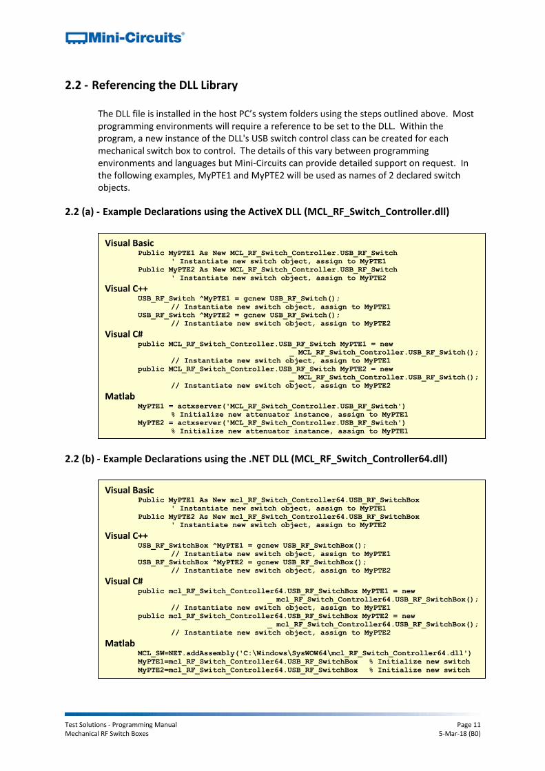
2.2 (a) - Example Declarations using the ActiveX DLL (MCL_RF_Switch_Controller.dll)
2.2 (b) - Example Declarations using the .NET DLL (MCL_RF_Switch_Controller64.dll)
Visual Basic Public MyPTE1 As New MCL_RF_Switch_Controller.USB_RF_Switch
' Instantiate new switch object, assign to MyPTE1
Public MyPTE2 As New MCL_RF_Switch_Controller.USB_RF_Switch
' Instantiate new switch object, assign to MyPTE2
Visual C++ USB_RF_Switch ^MyPTE1 = gcnew USB_RF_Switch();
// Instantiate new switch object, assign to MyPTE1
USB_RF_Switch ^MyPTE2 = gcnew USB_RF_Switch();
// Instantiate new switch object, assign to MyPTE2 Visual C#
public MCL_RF_Switch_Controller.USB_RF_Switch MyPTE1 = new
_ MCL_RF_Switch_Controller.USB_RF_Switch();
// Instantiate new switch object, assign to MyPTE1
public MCL_RF_Switch_Controller.USB_RF_Switch MyPTE2 = new
_ MCL_RF_Switch_Controller.USB_RF_Switch();
// Instantiate new switch object, assign to MyPTE2
Matlab MyPTE1 = actxserver('MCL_RF_Switch_Controller.USB_RF_Switch')
% Initialize new attenuator instance, assign to MyPTE1
MyPTE2 = actxserver('MCL_RF_Switch_Controller.USB_RF_Switch')
% Initialize new attenuator instance, assign to MyPTE1
Visual Basic Public MyPTE1 As New mcl_RF_Switch_Controller64.USB_RF_SwitchBox
' Instantiate new switch object, assign to MyPTE1
Public MyPTE2 As New mcl_RF_Switch_Controller64.USB_RF_SwitchBox
' Instantiate new switch object, assign to MyPTE2
Visual C++ USB_RF_SwitchBox ^MyPTE1 = gcnew USB_RF_SwitchBox();
// Instantiate new switch object, assign to MyPTE1
USB_RF_SwitchBox ^MyPTE2 = gcnew USB_RF_SwitchBox();
// Instantiate new switch object, assign to MyPTE2 Visual C#
public mcl_RF_Switch_Controller64.USB_RF_SwitchBox MyPTE1 = new
_ mcl_RF_Switch_Controller64.USB_RF_SwitchBox();
// Instantiate new switch object, assign to MyPTE1
public mcl_RF_Switch_Controller64.USB_RF_SwitchBox MyPTE2 = new
_ mcl_RF_Switch_Controller64.USB_RF_SwitchBox();
// Instantiate new switch object, assign to MyPTE2
Matlab MCL_SW=NET.addAssembly('C:\Windows\SysWOW64\mcl_RF_Switch_Controller64.dll')
MyPTE1=mcl_RF_Switch_Controller64.USB_RF_SwitchBox % Initialize new switch
MyPTE2=mcl_RF_Switch_Controller64.USB_RF_SwitchBox % Initialize new switch
Test Solutions - Programming Manual Page 12 Mechanical RF Switch Boxes 5-Mar-18 (B0)
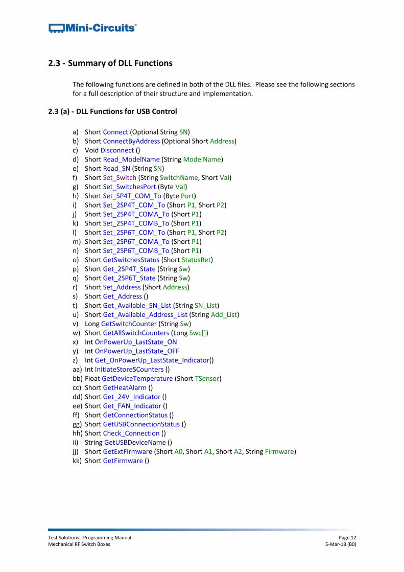
2.3 - Summary of DLL Functions
The following functions are defined in both of the DLL files. Please see the following sections for a full description of their structure and implementation.
2.3 (a) - DLL Functions for USB Control
a) Short Connect (Optional String SN) b) Short ConnectByAddress (Optional Short Address) c) Void Disconnect () d) Short Read_ModelName (String ModelName) e) Short Read_SN (String SN) f) Short Set_Switch (String SwitchName, Short Val) g) Short Set_SwitchesPort (Byte Val) h) Short Set_SP4T_COM_To (Byte Port) i) Short Set_2SP4T_COM_To (Short P1, Short P2) j) Short Set_2SP4T_COMA_To (Short P1) k) Short Set_2SP4T_COMB_To (Short P1) l) Short Set_2SP6T_COM_To (Short P1, Short P2) m) Short Set_2SP6T_COMA_To (Short P1) n) Short Set_2SP6T_COMB_To (Short P1) o) Short GetSwitchesStatus (Short StatusRet) p) Short Get_2SP4T_State (String Sw) q) Short Get_2SP6T_State (String Sw) r) Short Set_Address (Short Address) s) Short Get_Address () t) Short Get_Available_SN_List (String SN_List) u) Short Get_Available_Address_List (String Add_List) v) Long GetSwitchCounter (String Sw) w) Short GetAllSwitchCounters (Long Swc[]) x) Int OnPowerUp_LastState_ON y) Int OnPowerUp_LastState_OFF z) Int Get_OnPowerUp_LastState_Indicator() aa) Int InitiateStoreSCounters () bb) Float GetDeviceTemperature (Short TSensor) cc) Short GetHeatAlarm () dd) Short Get_24V_Indicator () ee) Short Get_FAN_Indicator () ff) Short GetConnectionStatus () gg) Short GetUSBConnectionStatus () hh) Short Check_Connection () ii) String GetUSBDeviceName () jj) Short GetExtFirmware (Short A0, Short A1, Short A2, String Firmware) kk) Short GetFirmware ()

Test Solutions - Programming Manual Page 13 Mechanical RF Switch Boxes 5-Mar-18 (B0)
2.3 (b) - DLL Functions for Ethernet Configuration (RC Models Only)
a) Short GetEthernet_CurrentConfig (Int IP1, Int IP2, Int IP3, Int IP4, Int Mask1, Int Mask2,
Int Mask3, Int Mask4, Int Gateway1, Int Gateway2, Int Gateway3, Int Gateway4) b) Short GetEthernet_IPAddress (Int b1, Int b2, Int b3, Int b4) c) Short GetEthernet_MACAddress (Int MAC1 , Int MAC2, Int MAC3, Int MAC4, Int MAC5,
Int MAC6) d) Short GetEthernet_NetworkGateway (Int b1, Int b2, Int b3, Int b4) e) Short GetEthernet_SubNetMask (Int b1, Int b2, Int b3, Int b4) f) Short GetEthernet_TCPIPPort (Int port) g) Short GetEthernet_UseDHCP () h) Short GetEthernet_UsePWD () i) Short GetEthernet_PWD (string Pwd) j) Short SaveEthernet_IPAddress (Int b1, Int b2, Int b3, Int b4) k) Short SaveEthernet_NetworkGateway (Int b1, Int b2, Int b3, Int b4) l) Short SaveEthernet_SubnetMask (Int b1, Int b2, Int b3, Int b4) m) Short SaveEthernet_TCPIPPort (Int port) n) Short SaveEthernet_UseDHCP (Int UseDHCP) o) Short SaveEthernet_UsePWD (Int UsePwd) p) Short SaveEthernet_PWD (String Pwd)

Test Solutions - Programming Manual Page 14 Mechanical RF Switch Boxes 5-Mar-18 (B0)
2.4 - DLL Functions for USB Control
These functions apply to all Mini-Circuits switch matrix models and provide a means to control the device over a USB connection.
2.4 (a) - Connect to Switch Matrix
Declaration Short Connect(Optional String SN)
Description
Initializes the USB connection to a switch matrix. If multiple switch matrices are connected to the same computer, then the serial number should be included, otherwise this can be omitted. The switch should be disconnected on completion of the program using the Disconnect function.
Parameters
Data Type Variable Description
String SN Optional. The serial number of the USB switch matrix. Can be omitted if only one switch matrix is connected.
Return Values
Data Type Value Description
Short 0 No connection was possible
1 Connection successfully established
2 Connection already established (Connect has been called more than once). The switch will continue to operate normally.
Examples
See Also Connect to Switch Matrix by Address Disconnect from Switch Matrix Get List of Connected Serial Numbers
Visual Basic status = MyPTE1.Connect(SN)
Visual C++ status = MyPTE1->Connect(SN);
Visual C# status = MyPTE1.Connect(SN);
Matlab status = MyPTE1.Connect(SN)

Test Solutions - Programming Manual Page 15 Mechanical RF Switch Boxes 5-Mar-18 (B0)
2.4 (b) - Connect to Switch Matrix by Address
Declaration Short ConnectByAddress(Optional Short Address)
Description
This function is called to initialize the USB connection to a switch matrix by referring to a user defined address. The address is an integer number from 1 to 255 which can be assigned using the Set_Address function (the factory default is 255). The connection process can take a few milliseconds so it is recommended that the connection be made once at the beginning of the routine and left open until the switch is no longer needed. The switch should be disconnected on completion of the program using the Disconnect function.
Parameters
Data Type Variable Description
Short Address Optional. The address of the USB switch matrix. Can be omitted if only one switch matrix is connected.
Return Values
Data Type Value Description
Short 0 No connection was possible
1 Connection successfully established
2 Connection already established (Connect has been called more than once)
Examples
See Also
Connect to Switch Matrix Disconnect from Switch Matrix Set Address of Switch Matrix Get Address of Switch Matrix
Visual Basic status = MyPTE1.ConnectByAddress(5)
Visual C++ status = MyPTE1->ConnectByAddress(5);
Visual C# status = MyPTE1.ConnectByAddress(5);
Matlab status = MyPTE1.connectByAddress(5)

Test Solutions - Programming Manual Page 16 Mechanical RF Switch Boxes 5-Mar-18 (B0)
2.4 (c) - Disconnect from Switch Matrix
Declaration Void Disconnect()
Description
This function is called to close the connection to the switch matrix after completion of the switching routine. It is strongly recommended that this function is used prior to ending the program. Failure to do so may result in a connection problem with the device. Should this occur, shut down the program and unplug the switch matrix from the computer, then reconnect the switch matrix before attempting to start again.
Parameters
Data Type Variable Description
None
Return Values
Data Type Value Description
None
Examples
See Also
Connect to Switch Matrix Connect to Switch Matrix by Address
Visual Basic MyPTE1.Disconnect()
Visual C++ MyPTE1->Disconnect();
Visual C# MyPTE1.Disconnect();
Matlab MyPTE1.Disconnect

Test Solutions - Programming Manual Page 17 Mechanical RF Switch Boxes 5-Mar-18 (B0)
2.4 (d) - Read Model Name of Switch Matrix
Declaration Short Read_ModelName(String ModelName)
Description
This function is called to determine the Mini-Circuits part number of the connected switch matrix. The user passes a string variable which is updated with the part number.
Parameters
Data Type Variable Description
String ModelName Required. A string variable that will be updated with the Mini-Circuits part number for the switch matrix.
Return Values
Data Type Value Description
Short 0 Command failed
1 Command completed successfully
Examples
See Also Read Serial Number of Switch Matrix
Visual Basic If MyPTE1.Read_ModelName(ModelName) > 0 Then
MsgBox ("The connected switch matrix is " & ModelName)
' Display a message stating the model name
End If Visual C++
if (MyPTE1->Read_ModelName(ModelName) > 0 )
{
MessageBox::Show("The connected switch matrix is " + ModelName);
// Display a message stating the model name
} Visual C#
if (MyPTE1.Read_ModelName(ref(ModelName)) > 0 )
{
MessageBox.Show("The connected switch matrix is " + ModelName);
// Display a message stating the model name
} Matlab
[status, ModelName] = MyPTE1.Read_ModelName(ModelName)
if status > 0
h = msgbox('The connected switch is ', ModelName)
% Display a message stating the model name
end
Test Solutions - Programming Manual Page 18 Mechanical RF Switch Boxes 5-Mar-18 (B0)
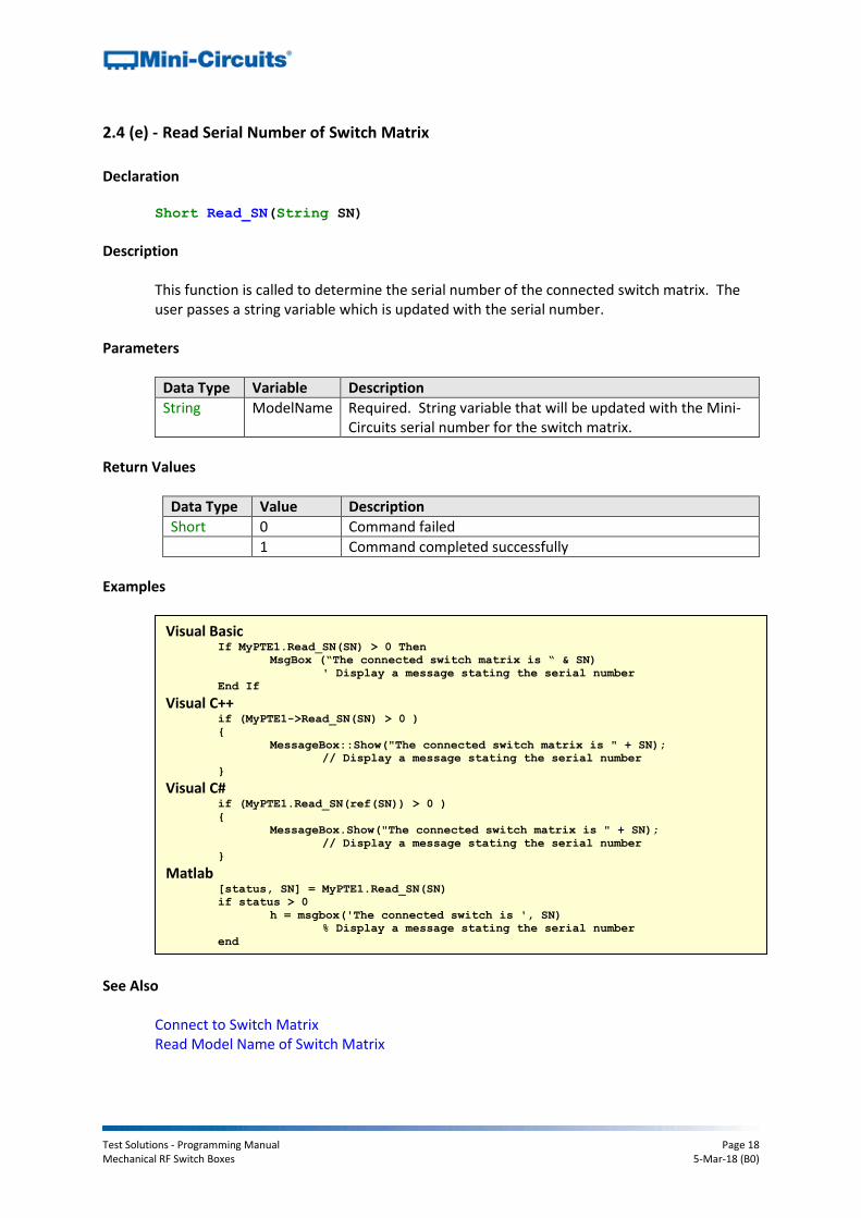
2.4 (e) - Read Serial Number of Switch Matrix
Declaration Short Read_SN(String SN)
Description
This function is called to determine the serial number of the connected switch matrix. The user passes a string variable which is updated with the serial number.
Parameters
Data Type Variable Description
String ModelName Required. String variable that will be updated with the Mini-Circuits serial number for the switch matrix.
Return Values
Data Type Value Description
Short 0 Command failed
1 Command completed successfully
Examples
See Also Connect to Switch Matrix Read Model Name of Switch Matrix
Visual Basic If MyPTE1.Read_SN(SN) > 0 Then
MsgBox (“The connected switch matrix is “ & SN)
' Display a message stating the serial number
End If Visual C++
if (MyPTE1->Read_SN(SN) > 0 )
{
MessageBox::Show("The connected switch matrix is " + SN);
// Display a message stating the serial number
} Visual C#
if (MyPTE1.Read_SN(ref(SN)) > 0 )
{
MessageBox.Show("The connected switch matrix is " + SN);
// Display a message stating the serial number
} Matlab
[status, SN] = MyPTE1.Read_SN(SN)
if status > 0
h = msgbox('The connected switch is ', SN)
% Display a message stating the serial number
end

Test Solutions - Programming Manual Page 19 Mechanical RF Switch Boxes 5-Mar-18 (B0)
2.4 (f) - Set Individual SPDT / Transfer Switch
Declaration Short Set_Switch(String SwitchName, Short Val)
Description
This function sets an individual SPDT or transfer switch within the switch matrix whilst leaving any other switches unchanged. The switches are designated A to H, as labeled on the front of the switch matrix (not all switches are available on all models).
Applies To
Model Serial Numbers
USB-xSPDT-A18 All serial numbers
RC-xSPDT-A18 All serial numbers
RC-2MTS-18 All serial numbers
ZTRC-xSPDT-A18 All serial numbers
Parameters
Data Type Variable Description
String SwitchName Required. String consisting of a single letter from “A” to “H”, designating the specific SPDT switch is to operate.
Short Val Required. An integer value to set the switch state: 0 = Connect Com port to port 1 (SPDT)
Connect J1 <> J3 and J2 <> J4 (transfer switch) 1 = Connect Com port to port 2 (SPDT)
Connect J1 <> J2 and J3 <> J4 (transfer switch)
Return Values
Data Type Value Description
Short 0 Command failed
1 Command completed successfully
2 Command failed (communication successful but 24V DC supply is disconnected). This return value is not applicable to all models (see “Applies To” table for Get 24V DC Supply Status).
Test Solutions - Programming Manual Page 20 Mechanical RF Switch Boxes 5-Mar-18 (B0)
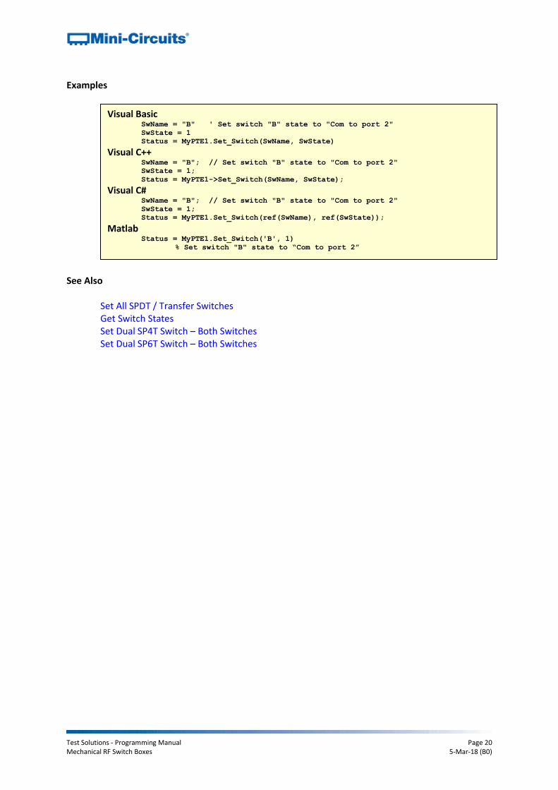
Examples
See Also
Set All SPDT / Transfer Switches Get Switch States Set Dual SP4T Switch – Both Switches Set Dual SP6T Switch – Both Switches
Visual Basic SwName = "B" ' Set switch "B" state to "Com to port 2"
SwState = 1
Status = MyPTE1.Set_Switch(SwName, SwState)
Visual C++ SwName = "B"; // Set switch "B" state to "Com to port 2"
SwState = 1;
Status = MyPTE1->Set_Switch(SwName, SwState);
Visual C# SwName = "B"; // Set switch "B" state to "Com to port 2" SwState = 1;
Status = MyPTE1.Set_Switch(ref(SwName), ref(SwState));
Matlab Status = MyPTE1.Set_Switch('B', 1)
% Set switch "B" state to “Com to port 2”

Test Solutions - Programming Manual Page 21 Mechanical RF Switch Boxes 5-Mar-18 (B0)
2.4 (g) - Set All SPDT / Transfer Switches
Declaration Short Set_SwitchesPort(Byte Val)
Description
Simultaneously sets all SPDT or transfer switches in a switch matrix. Applies To
Model Serial Numbers
USB-xSPDT-A18 All serial numbers
RC-xSPDT-A18 All serial numbers
RC-xMTS-18 All serial numbers
ZTRC-xSPDT-A18 All serial numbers
Parameters
Data Type Variable Description
Byte Val Required. Each bit corresponds to a single switch, with the LSB to switch “A” and the MSB to switch “H” (if applicable). Each bit can be: 0 = Connect Com port to port 1 (SPDT)
Connect J1 <> J3 and J2 <> J4 (transfer switch) 1 = Connect Com port to port 2 (SPDT)
Connect J1 <> J2 and J3 <> J4 (transfer switch) For example: Val=5 (binary 00000101) sets switches “A” and “C” for Com to port 2 and all other switches (if applicable) for Com to port 1.
Return Values
Data Type Value Description
Short 0 Command failed
1 Command completed successfully
2 Command failed (communication successful but 24V DC supply is disconnected). This return value is not applicable to all models (see “Applies To” table for Get 24V DC Supply Status).
Test Solutions - Programming Manual Page 22 Mechanical RF Switch Boxes 5-Mar-18 (B0)
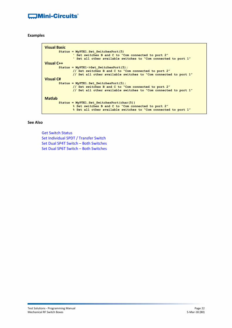
Examples
See Also
Get Switch Status Set Individual SPDT / Transfer Switch Set Dual SP4T Switch – Both Switches Set Dual SP6T Switch – Both Switches
Visual Basic Status = MyPTE1.Set_SwitchesPort(5)
' Set switches B and C to “Com connected to port 2”
' Set all other available switches to “Com connected to port 1”
Visual C++ Status = MyPTE1->Set_SwitchesPort(5);
// Set switches B and C to “Com connected to port 2”
// Set all other available switches to “Com connected to port 1” Visual C#
Status = MyPTE1.Set_SwitchesPort(5);
// Set switches B and C to “Com connected to port 2”
// Set all other available switches to “Com connected to port 1”
Matlab Status = MyPTE1.Set_SwitchesPort(char(5))
% Set switches B and C to “Com connected to port 2”
% Set all other available switches to “Com connected to port 1”

Test Solutions - Programming Manual Page 23 Mechanical RF Switch Boxes 5-Mar-18 (B0)
2.4 (h) - Set Single SP4T Switch
Declaration Short Set_SP4T_COM_To(Byte Port)
Description
Sets the state of the SP4T switch, connecting the Com (common) port to one of ports 1, 2, 3 or 4; or disconnecting all ports.
Applies To
Model Serial Numbers
USB-1SP4T-A18 All serial numbers
RC-xSP4T-x All serial numbers
For the RC-2SP4T-A18 dual SP4T switch box, this function will only set switch A.
Parameters
Data Type Variable Description
Byte Port Required. Byte value corresponding to the SP4T switch connection to be made. The 5 options for are: 0 = All ports disconnected 1 = Com connected to port 1 2 = Com connected to port 2 3 = Com connected to port 3 4 = Com connected to port 4
Return Values
Data Type Value Description
Short 0 Command failed or invalid switch state requested
1 Command completed successfully
2 Command failed (communication successful but 24V DC supply is disconnected). This return value is not applicable to all models (see “Applies To” table for Get 24V DC Supply Status).

Test Solutions - Programming Manual Page 24 Mechanical RF Switch Boxes 5-Mar-18 (B0)
Examples
See Also
Get Switch Status Get SP4T Switch State Set Dual SP4T Switch – Both Switches Set Dual SP4T – Switch A Set Dual SP4T – Switch B
Visual Basic Status = MyPTE1. Set_SP4T_COM_To (3)
' connect COM to port 3 Visual C++
Status = MyPTE1->Set_SP4T_COM_To(3);
// connect COM to port 3 Visual C#
Status = MyPTE1.Set_SP4T_COM_To(3);
// connect COM to port 3 Matlab
Status = MyPTE1.Set_SP4T_COM_To(3)
% connect COM to port 3

Test Solutions - Programming Manual Page 25 Mechanical RF Switch Boxes 5-Mar-18 (B0)
2.4 (i) - Set Dual SP4T Switch – Both Switches
Declaration Short Set_2SP4T_COM_To(Short P1, Short P2)
Description
Simultaneously sets the state of both SP4T switches within the dual SP4T switch box. Each switch’s Com (common) port can be connected to one of ports 1, 2, 3 or 4; or disconnected from all ports.
Applies To
Model Serial Numbers
RC-2SP4T-x All serial numbers
Parameters
Data Type Variable Description
Short P1 Required. Byte value specifying the connection to be made for switch A. The 5 options for are: 0 = All ports disconnected 1 = Com connected to port 1 2 = Com connected to port 2 3 = Com connected to port 3 4 = Com connected to port 4
Short P2 Required. Byte value specifying the connection to be made for switch B. The 5 options for are: 0 = All ports disconnected 1 = Com connected to port 1 2 = Com connected to port 2 3 = Com connected to port 3 4 = Com connected to port 4
Return Values
Data Type Value Description
Short 0 Command failed or invalid switch state requested
1 Command completed successfully

Test Solutions - Programming Manual Page 26 Mechanical RF Switch Boxes 5-Mar-18 (B0)
Examples
See Also
Set Dual SP4T – Switch A Set Dual SP4T – Switch B Get Dual SP4T Switch State
Visual Basic Status = MyPTE1.Set_2SP4T_COM_To (3, 0)
' set switch A COM to port 3 and switch B all ports disconnected Visual C++
Status = MyPTE1->Set_2SP4T_COM_To(3, 0);
// set switch A COM to port 3 and switch B all ports disconnected Visual C#
Status = MyPTE1.Set_2SP4T_COM_To(3, 0);
// set switch A COM to port 3 and switch B all ports disconnected Matlab
Status = MyPTE1.Set_2SP4T_COM_To(3, 0)
% set switch A COM to port 3 and switch B all ports disconnected

Test Solutions - Programming Manual Page 27 Mechanical RF Switch Boxes 5-Mar-18 (B0)
2.4 (j) - Set Dual SP4T – Switch A
Declaration Short Set_2SP4T_COMA_To(Short P1)
Description
Sets the state of switch A within the dual SP4T, leaving switch B unchanged. Switch A can have Com (common) port connected to one of ports 1, 2, 3 or 4; or disconnected from all ports. This function can also be used to set the state of the single SP4T switch in USB-1SP4T-A18 or RC-1SP4T-A18.
Applies To
Model Serial Numbers
RC-2SP4T-x All serial numbers
Parameters
Data Type Variable Description
Short P1 Required. Byte value specifying the connection to be made for switch A. The 5 options for are: 0 = All ports disconnected 1 = Com connected to port 1 2 = Com connected to port 2 3 = Com connected to port 3 4 = Com connected to port 4
Return Values
Data Type Value Description
Short 0 Command failed or invalid switch state requested
1 Command completed successfully

Test Solutions - Programming Manual Page 28 Mechanical RF Switch Boxes 5-Mar-18 (B0)
Examples
See Also
Set Dual SP4T Switch – Both Switches Set Dual SP4T – Switch B Get Dual SP4T Switch State
Visual Basic Status = MyPTE1.Set_2SP4T_COMA_To (3)
' set switch A COM to port 3 Visual C++
Status = MyPTE1->Set_2SP4T_COMA_To(3);
// set switch A COM to port 3 Visual C#
Status = MyPTE1.Set_2SP4T_COMA_To(3);
// set switch A COM to port 3 Matlab
Status = MyPTE1.Set_2SP4T_COMA_To(3)
% set switch A COM to port 3
Test Solutions - Programming Manual Page 29 Mechanical RF Switch Boxes 5-Mar-18 (B0)
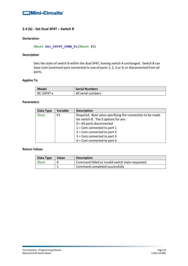
2.4 (k) - Set Dual SP4T – Switch B
Declaration Short Set_2SP4T_COMB_To(Short P1)
Description
Sets the state of switch B within the dual SP4T, leaving switch A unchanged. Switch B can have Com (common) port connected to one of ports 1, 2, 3 or 4; or disconnected from all ports.
Applies To
Model Serial Numbers
RC-2SP4T-x All serial numbers
Parameters
Data Type Variable Description
Short P1 Required. Byte value specifying the connection to be made for switch B. The 5 options for are: 0 = All ports disconnected 1 = Com connected to port 1 2 = Com connected to port 2 3 = Com connected to port 3 4 = Com connected to port 4
Return Values
Data Type Value Description
Short 0 Command failed or invalid switch state requested
1 Command completed successfully
Test Solutions - Programming Manual Page 30 Mechanical RF Switch Boxes 5-Mar-18 (B0)
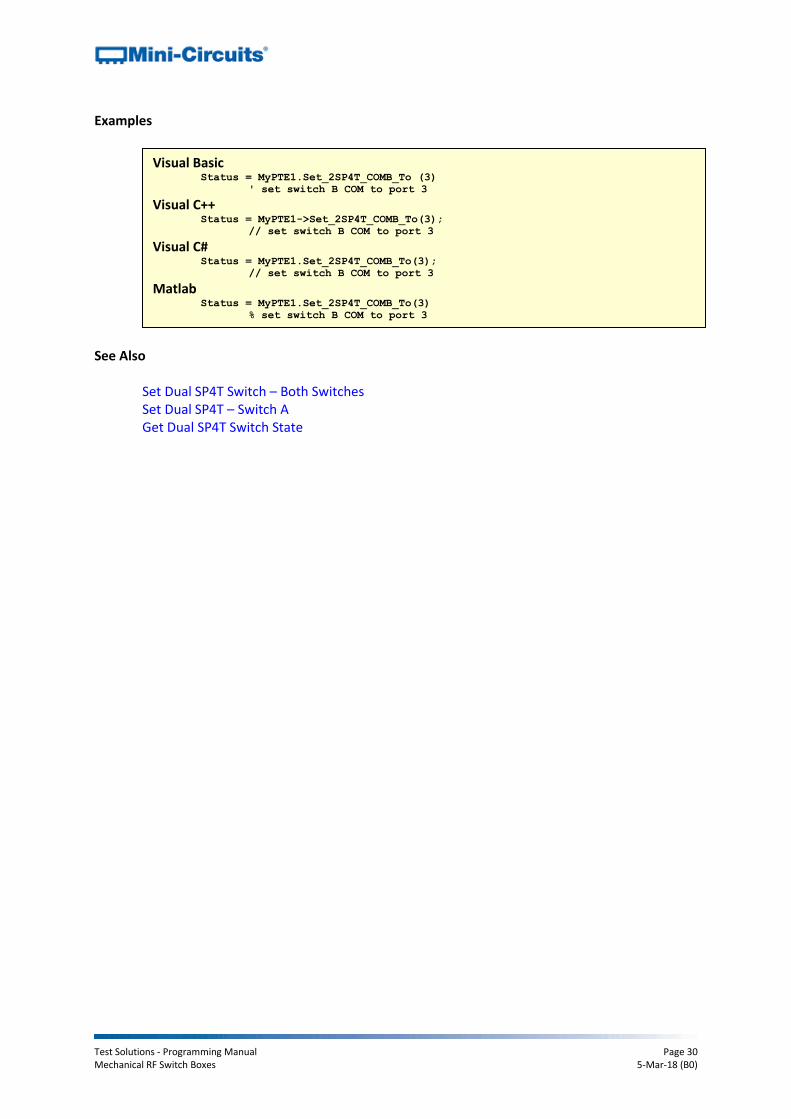
Examples
See Also
Set Dual SP4T Switch – Both Switches Set Dual SP4T – Switch A Get Dual SP4T Switch State
Visual Basic Status = MyPTE1.Set_2SP4T_COMB_To (3)
' set switch B COM to port 3 Visual C++
Status = MyPTE1->Set_2SP4T_COMB_To(3);
// set switch B COM to port 3 Visual C#
Status = MyPTE1.Set_2SP4T_COMB_To(3);
// set switch B COM to port 3 Matlab
Status = MyPTE1.Set_2SP4T_COMB_To(3)
% set switch B COM to port 3

Test Solutions - Programming Manual Page 31 Mechanical RF Switch Boxes 5-Mar-18 (B0)
2.4 (l) - Set SP6T Switch
Declaration Short Set_2SP6T_COM_To(Short P1, Short P2)
Description
Simultaneously sets the state of both SP6T switches within the dual SP6T switch box. The Com (common) port of each switch can be connected to one of ports 1 to 6; or be disconnected from all ports.
Applies To
Model Serial Numbers
RC-2SP6T-A12 All serial numbers
Parameters
Data Type Variable Description
Short P1 Required. Byte value specifying the connection to be made for switch A. The 7 options for are: 0 = All ports disconnected 1 = Com connected to port 1 2 = Com connected to port 2 3 = Com connected to port 3 4 = Com connected to port 4 5 = Com connected to port 5 6 = Com connected to port 6
Short P2 Required. Byte value specifying the connection to be made for switch B. The 7 options for are: 0 = All ports disconnected 1 = Com connected to port 1 2 = Com connected to port 2 3 = Com connected to port 3 4 = Com connected to port 4 5 = Com connected to port 5 6 = Com connected to port 6
Return Values
Data Type Value Description
Short 0 Command failed or invalid switch state requested
1 Command completed successfully
Test Solutions - Programming Manual Page 32 Mechanical RF Switch Boxes 5-Mar-18 (B0)
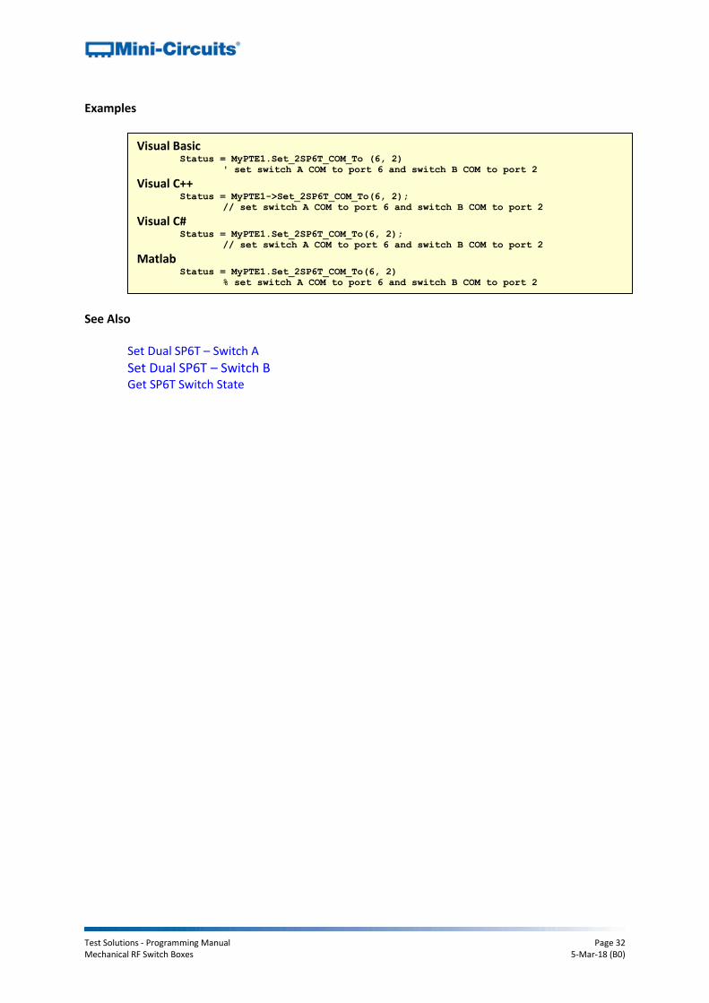
Examples
See Also
Set Dual SP6T – Switch A
Set Dual SP6T – Switch B Get SP6T Switch State
Visual Basic Status = MyPTE1.Set_2SP6T_COM_To (6, 2)
' set switch A COM to port 6 and switch B COM to port 2 Visual C++
Status = MyPTE1->Set_2SP6T_COM_To(6, 2);
// set switch A COM to port 6 and switch B COM to port 2 Visual C#
Status = MyPTE1.Set_2SP6T_COM_To(6, 2);
// set switch A COM to port 6 and switch B COM to port 2 Matlab
Status = MyPTE1.Set_2SP6T_COM_To(6, 2)
% set switch A COM to port 6 and switch B COM to port 2
Test Solutions - Programming Manual Page 33 Mechanical RF Switch Boxes 5-Mar-18 (B0)
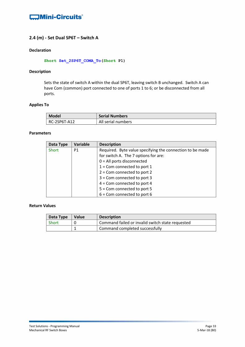
2.4 (m) - Set Dual SP6T – Switch A
Declaration Short Set_2SP6T_COMA_To(Short P1)
Description
Sets the state of switch A within the dual SP6T, leaving switch B unchanged. Switch A can have Com (common) port connected to one of ports 1 to 6; or be disconnected from all ports.
Applies To
Model Serial Numbers
RC-2SP6T-A12 All serial numbers
Parameters
Data Type Variable Description
Short P1 Required. Byte value specifying the connection to be made for switch A. The 7 options for are: 0 = All ports disconnected 1 = Com connected to port 1 2 = Com connected to port 2 3 = Com connected to port 3 4 = Com connected to port 4 5 = Com connected to port 5 6 = Com connected to port 6
Return Values
Data Type Value Description
Short 0 Command failed or invalid switch state requested
1 Command completed successfully

Test Solutions - Programming Manual Page 34 Mechanical RF Switch Boxes 5-Mar-18 (B0)
Examples
See Also
Set SP6T Switch Set Dual SP6T – Switch B Get SP6T Switch State
Visual Basic Status = MyPTE1.Set_2SP6T_COMA_To (3)
' set switch A COM to port 3 Visual C++
Status = MyPTE1->Set_2SP6T_COMA_To(3);
// set switch A COM to port 3 Visual C#
Status = MyPTE1.Set_2SP6T_COMA_To(3);
// set switch A COM to port 3 Matlab
Status = MyPTE1.Set_2SP6T_COMA_To(3)
% set switch A COM to port 3

Test Solutions - Programming Manual Page 35 Mechanical RF Switch Boxes 5-Mar-18 (B0)
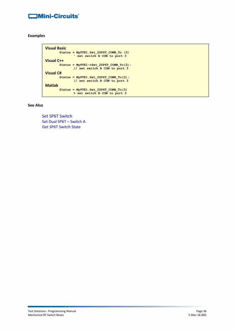
2.4 (n) - Set Dual SP6T – Switch B
Declaration Short Set_2SP6T_COMB_To(Short P1)
Description
Sets the state of switch B within the dual SP6T, leaving switch A unchanged. Switch B can have Com (common) port connected to one of ports 1, 2, 3 or 4; or disconnected from all ports.
Applies To
Model Serial Numbers
RC-2SP6T-A12 All serial numbers
Parameters
Data Type Variable Description
Short P1 Required. Byte value specifying the connection to be made for switch B. The 7 options for are: 0 = All ports disconnected 1 = Com connected to port 1 2 = Com connected to port 2 3 = Com connected to port 3 4 = Com connected to port 4 5 = Com connected to port 5 6 = Com connected to port 6
Return Values
Data Type Value Description
Short 0 Command failed or invalid switch state requested
1 Command completed successfully
Test Solutions - Programming Manual Page 36 Mechanical RF Switch Boxes 5-Mar-18 (B0)
Examples
See Also
Set SP6T Switch Set Dual SP6T – Switch A Get SP6T Switch State
Visual Basic Status = MyPTE1.Set_2SP6T_COMB_To (3)
' set switch B COM to port 3 Visual C++
Status = MyPTE1->Set_2SP6T_COMB_To(3);
// set switch B COM to port 3 Visual C#
Status = MyPTE1.Set_2SP6T_COMB_To(3);
// set switch B COM to port 3 Matlab
Status = MyPTE1.Set_2SP6T_COMB_To(3)
% set switch B COM to port 3
Test Solutions - Programming Manual Page 37 Mechanical RF Switch Boxes 5-Mar-18 (B0)
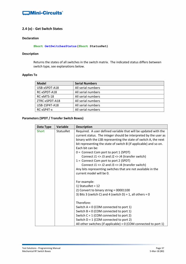
2.4 (o) - Get Switch States
Declaration Short GetSwitchesStatus(Short StatusRet)
Description
Returns the states of all switches in the switch matrix. The indicated status differs between switch type, see explanations below.
Applies To
Model Serial Numbers
USB-xSPDT-A18 All serial numbers
RC-xSPDT-A18 All serial numbers
RC-xMTS-18 All serial numbers
ZTRC-xSPDT-A18 All serial numbers
USB-1SP4T-A18 All serial numbers
RC-xSP4T-x All serial numbers
Parameters (SPDT / Transfer Switch Boxes)
Data Type Variable Description
Short StatusRet Required. A user defined variable that will be updated with the current status. The integer should be interpreted by the user as binary with the LSB representing the state of switch A, the next bit representing the state of switch B (if applicable) and so on. Each bit can be: 0 = Connect Com port to port 1 (SPDT)
Connect J1 <> J3 and J2 <> J4 (transfer switch) 1 = Connect Com port to port 2 (SPDT)
Connect J1 <> J2 and J3 <> J4 (transfer switch) Any bits representing switches that are not available in the current model will be 0. For example: 1) StatusRet = 12 2) Convert to binary string = 00001100 3) Bits 3 (switch C) and 4 (switch D) = 1, all others = 0 Therefore: Switch A = 0 (COM connected to port 1) Switch B = 0 (COM connected to port 1) Switch C = 1 (COM connected to port 2) Switch D = 1 (COM connected to port 2) All other switches (if applicable) = 0 (COM connected to port 1)
Test Solutions - Programming Manual Page 38 Mechanical RF Switch Boxes 5-Mar-18 (B0)
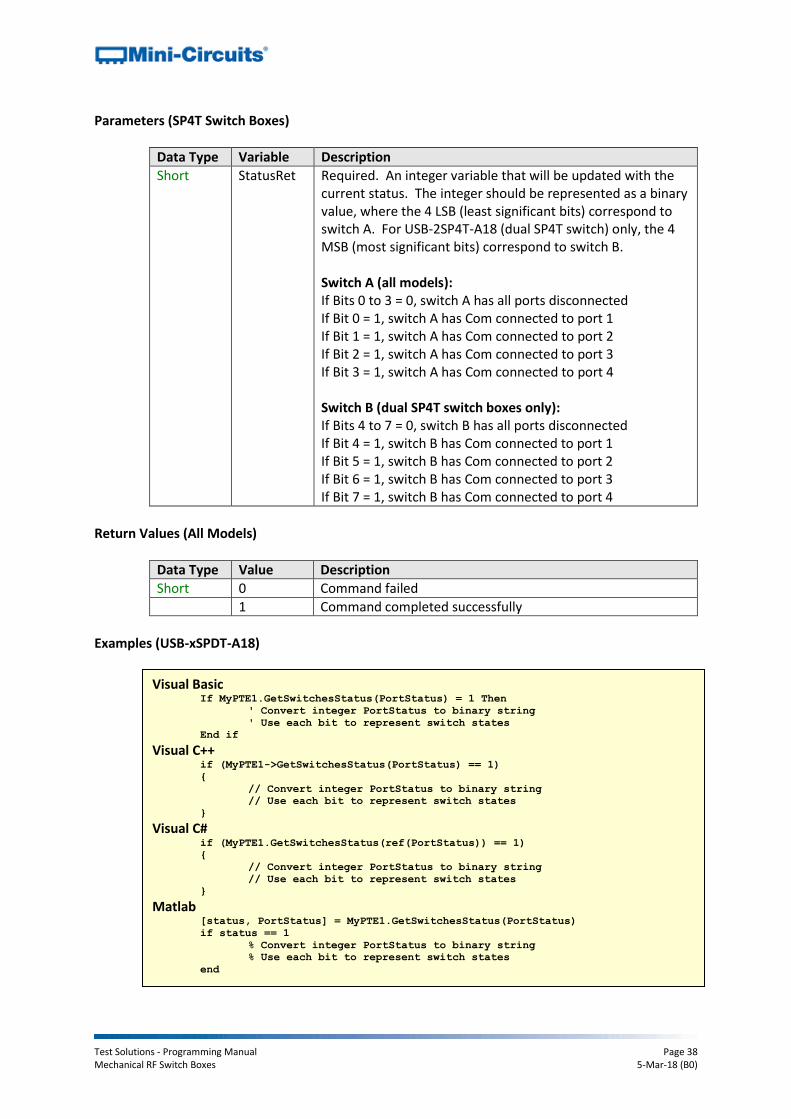
Parameters (SP4T Switch Boxes)
Data Type Variable Description
Short StatusRet Required. An integer variable that will be updated with the current status. The integer should be represented as a binary value, where the 4 LSB (least significant bits) correspond to switch A. For USB-2SP4T-A18 (dual SP4T switch) only, the 4 MSB (most significant bits) correspond to switch B. Switch A (all models): If Bits 0 to 3 = 0, switch A has all ports disconnected If Bit 0 = 1, switch A has Com connected to port 1 If Bit 1 = 1, switch A has Com connected to port 2 If Bit 2 = 1, switch A has Com connected to port 3 If Bit 3 = 1, switch A has Com connected to port 4 Switch B (dual SP4T switch boxes only): If Bits 4 to 7 = 0, switch B has all ports disconnected If Bit 4 = 1, switch B has Com connected to port 1 If Bit 5 = 1, switch B has Com connected to port 2 If Bit 6 = 1, switch B has Com connected to port 3 If Bit 7 = 1, switch B has Com connected to port 4
Return Values (All Models)
Data Type Value Description
Short 0 Command failed
1 Command completed successfully
Examples (USB-xSPDT-A18)
Visual Basic If MyPTE1.GetSwitchesStatus(PortStatus) = 1 Then
' Convert integer PortStatus to binary string
' Use each bit to represent switch states
End if Visual C++
if (MyPTE1->GetSwitchesStatus(PortStatus) == 1)
{
// Convert integer PortStatus to binary string
// Use each bit to represent switch states }
Visual C# if (MyPTE1.GetSwitchesStatus(ref(PortStatus)) == 1)
{
// Convert integer PortStatus to binary string
// Use each bit to represent switch states
} Matlab
[status, PortStatus] = MyPTE1.GetSwitchesStatus(PortStatus)
if status == 1
% Convert integer PortStatus to binary string
% Use each bit to represent switch states
end

Test Solutions - Programming Manual Page 39 Mechanical RF Switch Boxes 5-Mar-18 (B0)
Examples (USB-1SP4T-A18)
Visual Basic If MyPTE1.GetSwitchesStatus(PortStatus) = 1 Then
Select Case PortStatus
Case 0
' switch is disconnected
Case 1
' switch connected, com to port 1
Case 2
' switch connected, com to port 2
Case 4
' switch connected, com to port 3
Case 8
' switch connected, com to port 4
End Select
End if
Visual C++ if (MyPTE1->GetSwitchesStatus(PortStatus) == 1)
{
switch(PortStatus){
case 0:
// switch is disconnected
case 1:
// switch connected, com to port 1
case 2:
// switch connected, com to port 2
case 4:
// switch connected, com to port 3
case 8:
// switch connected, com to port 4
}
} Visual C#
if (MyPTE1.GetSwitchesStatus(ref(PortStatus))==1)
{
switch(PortStatus)
{
case 0:
// switch is disconnected
case 1:
// switch connected, com to port 1
case 2:
// switch connected, com to port 2
case 4:
// switch connected, com to port 3
case 8:
// switch connected, com to port 4
}
} Matlab
[status, PortStatus] = MyPTE1.GetSwitchesStatus(PortStatus)
if status == 1
switch PortStatus
case 0
% switch is disconnected
case 1
% switch connected, com to port 1
case 2
% switch connected, com to port 2
case 4
% switch connected, com to port 3
case 8
% switch connected, com to port 4
end
end

Test Solutions - Programming Manual Page 40 Mechanical RF Switch Boxes 5-Mar-18 (B0)
See Also
Set Individual SPDT / Transfer Switch Set All SPDT / Transfer Switches Set Single SP4T Switch Set SP6T Switch Get Dual SP4T Switch State

Test Solutions - Programming Manual Page 41 Mechanical RF Switch Boxes 5-Mar-18 (B0)
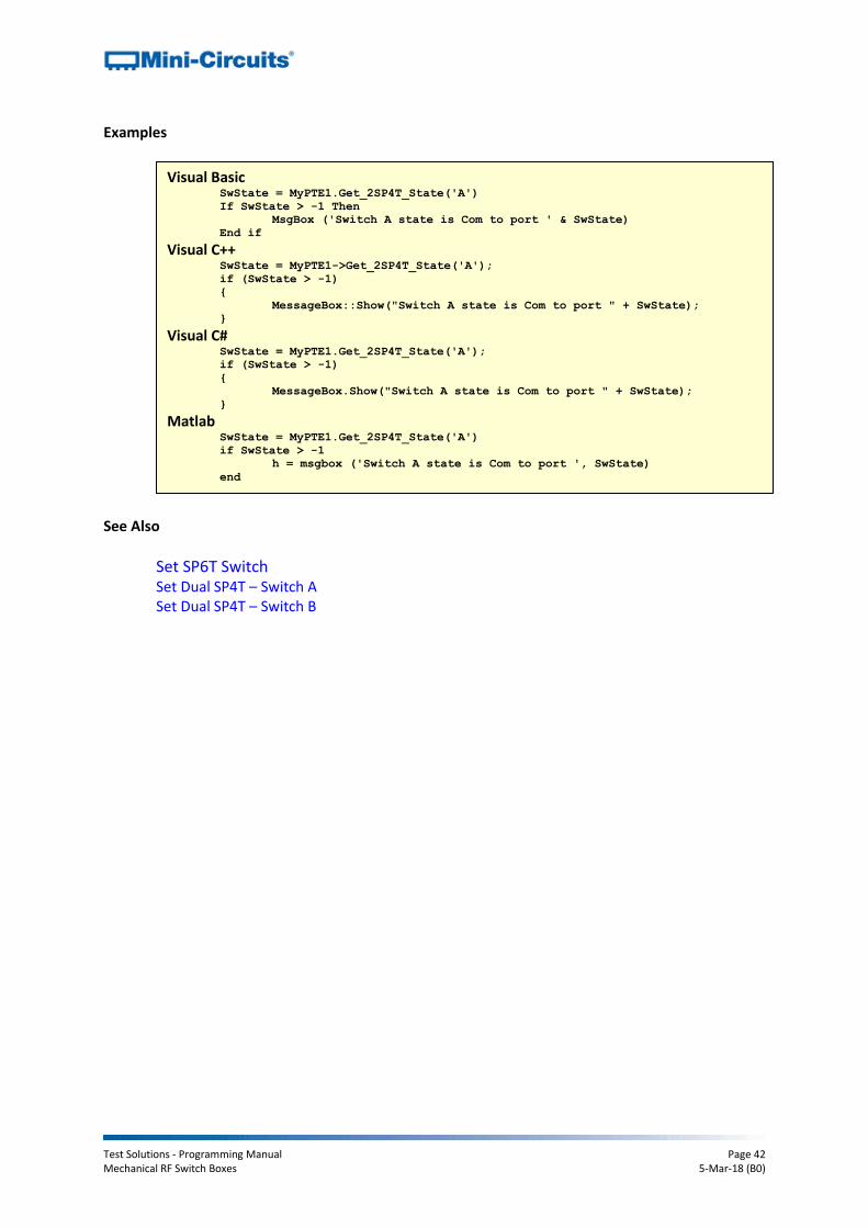
2.4 (p) - Get SP4T Switch State
Declaration Short Get_2SP4T_State(String sw)
Description
Returns the state of an SP4T switch box.
Applies To
Model Serial Numbers
USB-1SP4T-A18 All serial numbers
RC-xSP4T-x All serial numbers
Parameters
Data Type Variable Description
String sw Required. String to indicate which SP4T switch state to return, either “A” or “B”.
Return Values
Data Type Value Description
Short -1 Command failed
0 Switch has all ports disconnected
1 Switch has Com port connected to port 1
2 Switch has Com port connected to port 2
3 Switch has Com port connected to port 3
4 Switch has Com port connected to port 4
Test Solutions - Programming Manual Page 42 Mechanical RF Switch Boxes 5-Mar-18 (B0)
Examples
See Also
Set SP6T Switch Set Dual SP4T – Switch A Set Dual SP4T – Switch B
Visual Basic SwState = MyPTE1.Get_2SP4T_State('A')
If SwState > -1 Then
MsgBox ('Switch A state is Com to port ' & SwState)
End if
Visual C++ SwState = MyPTE1->Get_2SP4T_State('A');
if (SwState > -1)
{
MessageBox::Show("Switch A state is Com to port " + SwState);
} Visual C#
SwState = MyPTE1.Get_2SP4T_State('A');
if (SwState > -1)
{
MessageBox.Show("Switch A state is Com to port " + SwState);
} Matlab
SwState = MyPTE1.Get_2SP4T_State('A')
if SwState > -1
h = msgbox ('Switch A state is Com to port ', SwState)
end
Test Solutions - Programming Manual Page 43 Mechanical RF Switch Boxes 5-Mar-18 (B0)
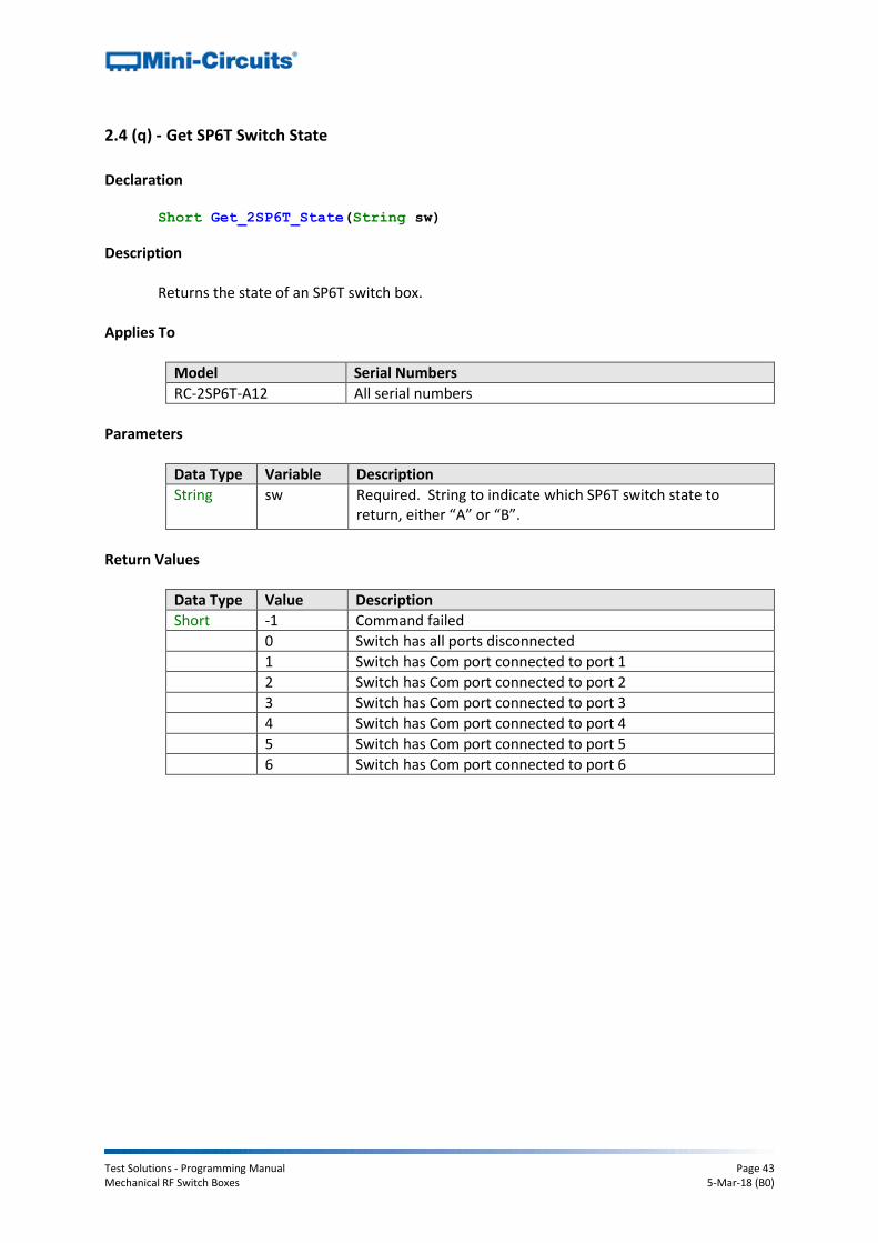
2.4 (q) - Get SP6T Switch State
Declaration Short Get_2SP6T_State(String sw)
Description
Returns the state of an SP6T switch box.
Applies To
Model Serial Numbers
RC-2SP6T-A12 All serial numbers
Parameters
Data Type Variable Description
String sw Required. String to indicate which SP6T switch state to return, either “A” or “B”.
Return Values
Data Type Value Description
Short -1 Command failed
0 Switch has all ports disconnected
1 Switch has Com port connected to port 1
2 Switch has Com port connected to port 2
3 Switch has Com port connected to port 3
4 Switch has Com port connected to port 4
5 Switch has Com port connected to port 5
6 Switch has Com port connected to port 6

Test Solutions - Programming Manual Page 44 Mechanical RF Switch Boxes 5-Mar-18 (B0)
Examples
See Also
Set SP6T Switch Set Dual SP6T – Switch A
Set Dual SP6T – Switch B
Visual Basic SwState = MyPTE1.Get_2SP6T_State('A')
If SwState > -1 Then
MsgBox ('Switch A state is Com to port ' & SwState)
End if
Visual C++ SwState = MyPTE1->Get_2SP6T_State('A');
if (SwState > -1)
{
MessageBox::Show("Switch A state is Com to port " + SwState);
} Visual C#
SwState = MyPTE1.Get_2SP6T_State('A');
if (SwState > -1)
{
MessageBox.Show("Switch A state is Com to port " + SwState);
} Matlab
SwState = MyPTE1.Get_2SP6T_State('A')
if SwState > -1
h = msgbox ('Switch A state is Com to port ', SwState)
end
Test Solutions - Programming Manual Page 45 Mechanical RF Switch Boxes 5-Mar-18 (B0)
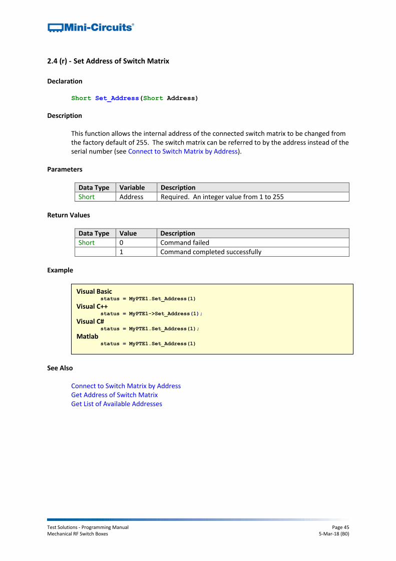
2.4 (r) - Set Address of Switch Matrix
Declaration Short Set_Address(Short Address)
Description
This function allows the internal address of the connected switch matrix to be changed from the factory default of 255. The switch matrix can be referred to by the address instead of the serial number (see Connect to Switch Matrix by Address).
Parameters
Data Type Variable Description
Short Address Required. An integer value from 1 to 255
Return Values
Data Type Value Description
Short 0 Command failed
1 Command completed successfully
Example
See Also
Connect to Switch Matrix by Address Get Address of Switch Matrix Get List of Available Addresses
Visual Basic status = MyPTE1.Set_Address(1)
Visual C++ status = MyPTE1->Set_Address(1);
Visual C# status = MyPTE1.Set_Address(1);
Matlab status = MyPTE1.Set_Address(1)
Test Solutions - Programming Manual Page 46 Mechanical RF Switch Boxes 5-Mar-18 (B0)
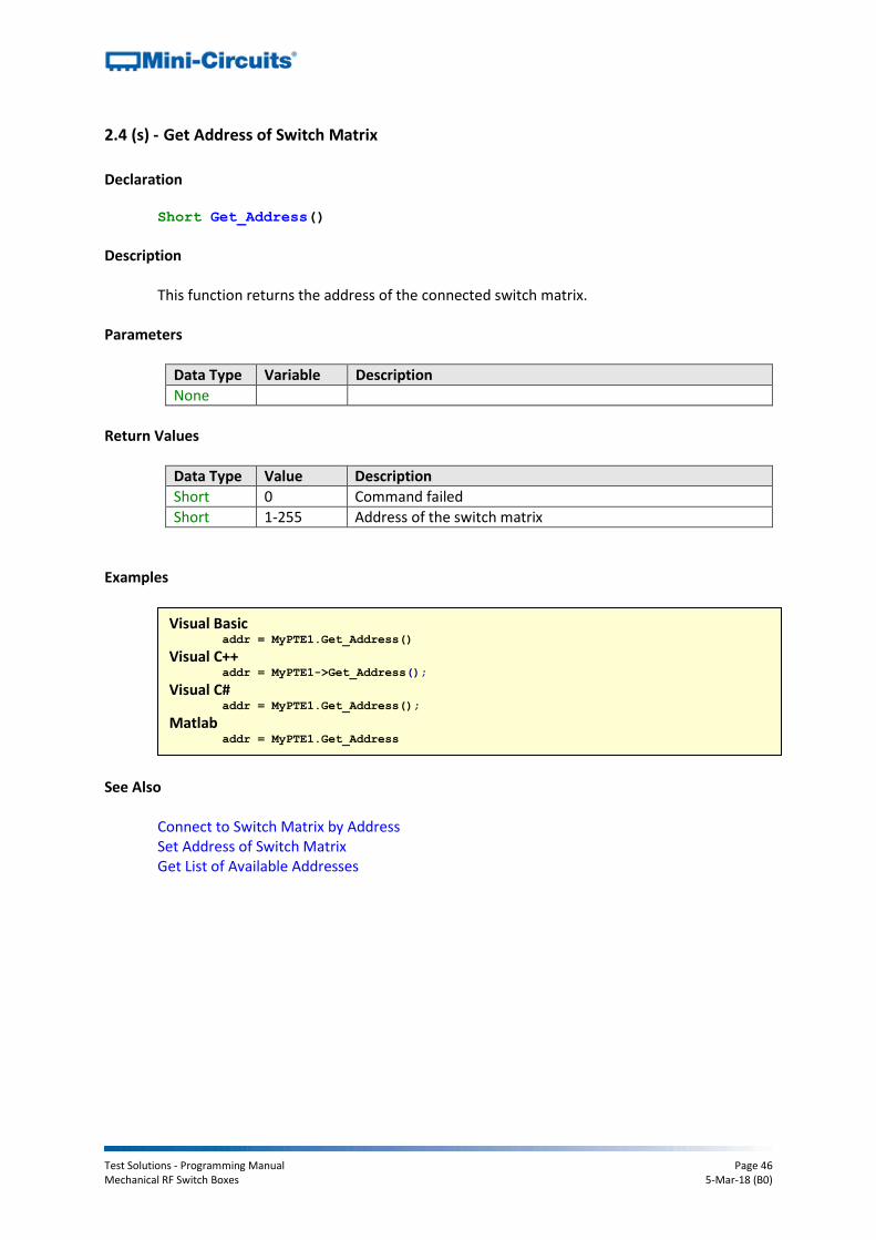
2.4 (s) - Get Address of Switch Matrix
Declaration Short Get_Address()
Description
This function returns the address of the connected switch matrix. Parameters
Data Type Variable Description
None
Return Values
Data Type Value Description
Short 0 Command failed
Short 1-255 Address of the switch matrix
Examples
See Also
Connect to Switch Matrix by Address Set Address of Switch Matrix Get List of Available Addresses
Visual Basic addr = MyPTE1.Get_Address()
Visual C++ addr = MyPTE1->Get_Address();
Visual C# addr = MyPTE1.Get_Address();
Matlab addr = MyPTE1.Get_Address

Test Solutions - Programming Manual Page 47 Mechanical RF Switch Boxes 5-Mar-18 (B0)
2.4 (t) - Get List of Connected Serial Numbers
Declaration Short Get_Available_SN_List(String SN_List)
Description
This function takes a user defined variable and updates it with a list of serial numbers for all available (currently connected) switch matrices.
Parameters
Data Type Variable Description
String SN_List Required. String variable which will be updated with a list of all available serial numbers, separated by a single space character; for example “11301020001 11301020002 11301020003”.
Return Values
Data Type Value Description
Short 0 Command failed
Short 1 Command completed successfully
Example
See Also Connect to Switch Matrix Get List of Available Addresses
Visual Basic If MyPTE1.Get_Available_SN_List(SN_List) > 0 Then
array_SN() = Split(SN_List, " ")
' Split the list into an array of serial numbers
For i As Integer = 0 To array_SN.Length - 1
' Loop through the array and use each serial number
Next
End If Visual C++
if (MyPTE1 ->Get_Available_SN_List(SN_List) > 0)
{
// split the List into array of SN's
} Visual C#
if (MyPTE1.Get_Available_SN_List(ref(SN_List)) > 0)
{
// split the List into array of SN's
} Matlab
[status, SN_List] = MyPTE1.Get_Available_SN_List(SN_List)
if status > 0
% split the List into array of SN's
end

Test Solutions - Programming Manual Page 48 Mechanical RF Switch Boxes 5-Mar-18 (B0)
2.4 (u) - Get List of Available Addresses
Declaration Short Get_Available_Address_List(String Add_List)
Description
This function takes a user defined variable and updates it with a list of addresses of all connected switch matrices.
Parameters
Data Type Variable Description
String Add_List Required. String variable which the function will update with a list of addresses separated by a single space character, for example, “5 101 254 255”
Return Values
Data Type Value Description
Short 0 Command failed
Short 1 Command completed successfully
Example
See Also
Connect to Switch Matrix by Address Get List of Connected Serial Numbers
Visual Basic If MyPTE1.Get_Available_Add_List(st_Ad_List) > 0 Then
' Get list of available addresses
array_Ad() = Split(st_Ad_List, " ")
' Split the list into an array of addresses
For i As Integer = 0 To array_Ad.Length - 1
' Loop through the array and use each address
Next
End If Visual C++
if (MyPTE1->Get_Available_Address_List(Add_List) > 0);
{ // split the List into array of Addresses
} Visual C#
if (MyPTE1.Get_Available_Address_List(ref(Add_List)) > 0)
{ // split the List into array of Addresses
} Matlab
[status, Add_List] = MyPTE1.Get_Available_Address_List(Add_List)
if status > 0
% split the List into array of Addresses
end

Test Solutions - Programming Manual Page 49 Mechanical RF Switch Boxes 5-Mar-18 (B0)
2.4 (v) - Get SPDT / Transfer Switch Counter
Declaration Long GetSwitchCounter(String Sw)
Description
Returns the number of switching cycles undertaken by an individual switch (specified by the user) within an SPDT or transfer switch box.
Applies To
Model Serial Numbers
USB-1SPDT-A18 From 11309160001 (firmware version C3 required)
USB-2SPDT-A18 From 11311270010 (firmware version C3 required)
USB-3SPDT-A18 From 11310100001 (firmware version C3 required)
USB-4SPDT-A18 From 11310100009 (firmware version C3 required)
USB-8SPDT-A18 From 11309290001 (firmware version C3 required)
RC-xSPDT-A18 All serial numbers
RC-xMTS-18 All serial numbers
ZTRC-xSPDT-A18 All serial numbers
Parameters
Data Type Variable Description
String Sw Required. The switch name, from “A” to “H” (model dependent), designating the specific switch to monitor.
Return Values
Data Type Value Description
Short -1 Command failed
Short Count The number of switch cycles for the specified switch
Examples
See Also
Get All Switch Counters Save Switch Counters
Visual Basic SwCount = MyPTE1.GetSwitchCounter("B")
MsgBox(SwCount & " switch cycles.")
Visual C++ SwCount = MyPTE1->GetSwitchCounter("B");
MessageBox::Show(SwCount + " switch cycles.");
Visual C# SwCount = MyPTE1.GetSwitchCounter("B");
MessageBox.Show(SwCount + " switch cycles.");
Matlab SwCount = MyPTE1.GetSwitchCounter("B")
h = msgbox(SwCount, ' switch cycles.')
Test Solutions - Programming Manual Page 50 Mechanical RF Switch Boxes 5-Mar-18 (B0)
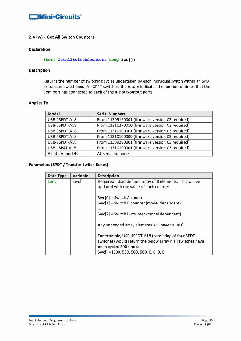
2.4 (w) - Get All Switch Counters
Declaration Short GetAllSwitchCounters(Long Swc[])
Description
Returns the number of switching cycles undertaken by each individual switch within an SPDT or transfer switch box. For SP4T switches, the return indicates the number of times that the Com port has connected to each of the 4 input/output ports.
Applies To
Model Serial Numbers
USB-1SPDT-A18 From 11309160001 (firmware version C3 required)
USB-2SPDT-A18 From 11311270010 (firmware version C3 required)
USB-3SPDT-A18 From 11310100001 (firmware version C3 required)
USB-4SPDT-A18 From 11310100009 (firmware version C3 required)
USB-8SPDT-A18 From 11309290001 (firmware version C3 required)
USB-1SP4T-A18 From 11310100001 (firmware version C3 required)
All other models All serial numbers
Parameters (SPDT / Transfer Switch Boxes)
Data Type Variable Description
Long Swc[] Required. User defined array of 8 elements. This will be updated with the value of each counter. Swc[0] = Switch A counter Swc[1] = Switch B counter (model dependent) … Swc[7] = Switch H counter (model dependent) Any unneeded array elements will have value 0 For example, USB-4SPDT-A18 (consisting of four SPDT switches) would return the below array if all switches have been cycled 500 times: Swc[] = {500, 500, 500, 500, 0, 0, 0, 0}

Test Solutions - Programming Manual Page 51 Mechanical RF Switch Boxes 5-Mar-18 (B0)
Parameters
Data Type Variable Description
Long Swc[] Required. User defined array of 8 elements. This will be updated with the values of each of the counters. All SP4T models: Swc[0] = Counter of Switch A Com to port 1 connections Swc[1] = Counter of Switch A Com to port 2 connections Swc[2] = Counter of Switch A Com to port 3 connections Swc[3] = Counter of Switch A Com to port 4 connections Dual SP4T models only: Swc[4] = Counter of Switch B Com to port 1 connections Swc[5] = Counter of Switch B Com to port 2 connections Swc[6] = Counter of Switch B Com to port 3 connections Swc[7] = Counter of Switch B Com to port 4 connections For example, USB-1SP4T-A18 (single SP4T switch) would return the below array if all 4 input/output ports have been connected to the Com port 500 times: Swc[] = {500, 500, 500, 500, 0, 0, 0, 0}
Return Values
Data Type Value Description
Short 0 Command failed
Short 1 Command completed successfully
Examples
See Also
Get SPDT / Transfer Switch Counter Save Switch Counters
Visual Basic status = MyPTE1.GetSwitchCounter(SwCounter)
MsgBox("Switch A: " & SwCounter(0) & " cycles.")
MsgBox("Switch H: " & SwCounter(7) & " cycles.")
Visual C++ status = MyPTE1->GetSwitchCounter(SwCounter);
MessageBox::Show("Switch A: " + SwCounter[0] + " cycles.");
MessageBox::Show("Switch H: " + SwCounter[7] + " cycles.");
Visual C# status = MyPTE1.GetSwitchCounter(SwCounter[8]);
MessageBox.Show("Switch A: " + SwCounter[0] + " cycles.");
MessageBox.Show("Switch H: " + SwCounter[7] + " cycles.");
Matlab

Test Solutions - Programming Manual Page 52 Mechanical RF Switch Boxes 5-Mar-18 (B0)
2.4 (x) - Set Power-Up Mode - Last Switch States
Declaration Int OnPowerUp_LastState_ON()
Description
Sets the switch box to power-up with all switches in the last remembered state (the last saved state that they occupied prior to DC power being removed). If the Save Switch Counters & States command is not used prior to powering off the switch box then the last state may not be remembered accurately and the switch box will power-up in the default state.
Requirements
Firmware version D1 or later Return Values
Data Type Value Description
Int 0 Command failed
1 Command completed successfully
Example
See Also
Set Power-Up Mode - Default Switch States Get Power-Up Mode Save Switch Counters & States
Visual Basic status = MyPTE1.OnPowerUp_LastState_ON()
Visual C++ status = MyPTE1->OnPowerUp_LastState_ON();
Visual C# status = MyPTE1.OnPowerUp_LastState_ON();
Matlab status = MyPTE1.OnPowerUp_LastState_ON()

Test Solutions - Programming Manual Page 53 Mechanical RF Switch Boxes 5-Mar-18 (B0)
2.4 (y) - Set Power-Up Mode - Default Switch States
Declaration Int OnPowerUp_LastState_OFF()
Description
Sets the switch box to power up with all switches in the default state (SP4T and SP6T switches with all ports disconnected and SPDT switches with Com connected to port 1).
Requirements
Firmware version D1 or later Return Values
Data Type Value Description
Int 0 Command failed
1 Command completed successfully
Example
See Also
Set Power-Up Mode - Last Switch States Get Power-Up Mode Save Switch Counters & States
Visual Basic status = MyPTE1.OnPowerUp_LastState_OFF()
Visual C++ status = MyPTE1->OnPowerUp_LastState_OFF();
Visual C# status = MyPTE1.OnPowerUp_LastState_OFF();
Matlab status = MyPTE1.OnPowerUp_LastState_OFF()
Test Solutions - Programming Manual Page 54 Mechanical RF Switch Boxes 5-Mar-18 (B0)
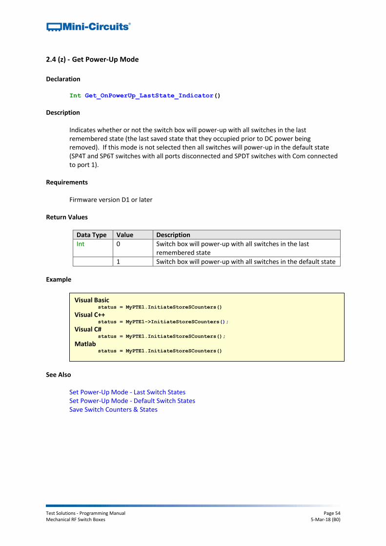
2.4 (z) - Get Power-Up Mode
Declaration Int Get_OnPowerUp_LastState_Indicator()
Description
Indicates whether or not the switch box will power-up with all switches in the last remembered state (the last saved state that they occupied prior to DC power being removed). If this mode is not selected then all switches will power-up in the default state (SP4T and SP6T switches with all ports disconnected and SPDT switches with Com connected to port 1).
Requirements
Firmware version D1 or later Return Values
Data Type Value Description
Int 0 Switch box will power-up with all switches in the last remembered state
1 Switch box will power-up with all switches in the default state
Example
See Also
Set Power-Up Mode - Last Switch States Set Power-Up Mode - Default Switch States Save Switch Counters & States
Visual Basic status = MyPTE1.InitiateStoreSCounters()
Visual C++ status = MyPTE1->InitiateStoreSCounters();
Visual C# status = MyPTE1.InitiateStoreSCounters();
Matlab status = MyPTE1.InitiateStoreSCounters()

Test Solutions - Programming Manual Page 55 Mechanical RF Switch Boxes 5-Mar-18 (B0)
2.4 (aa) - Save Switch Counters & States
Declaration Int InitiateStoreSCounters()
Description
Transfers the latest switch counters and switch states from temporary to permanent memory. During normal operation, this data is internally stored in volatile memory but automatically updated into permanent memory every 3 minutes. This command should be sent following completion of all switching routines and prior to powering off the switch in order to ensure that the data is permanently saved.
Requirements
Firmware version D1 or later Return Values
Data Type Value Description
Short 0 Command failed (or has already been sent by the user within the last 3 minutes)
1 Command completed successfully
Example
See Also
Get SPDT / Transfer Switch Counter Get All Switch Counters
Visual Basic status = MyPTE1.InitiateStoreSCounters()
Visual C++ status = MyPTE1->InitiateStoreSCounters();
Visual C# status = MyPTE1.InitiateStoreSCounters();
Matlab status = MyPTE1.InitiateStoreSCounters()

Test Solutions - Programming Manual Page 56 Mechanical RF Switch Boxes 5-Mar-18 (B0)
2.4 (bb) - Get Temperature of Switch Matrix
Declaration Float GetDeviceTemperature(Short TSensor)
Description
Returns the internal temperature measured at 1 of the internal sensors (model dependent):
USB-1SPDT-A18 / RC-1SPDT-A18 (1 sensor)
USB-1SP4T-A18 / RC-1SP4T-A18 (1 sensor)
RC-2MTS-18 (2 sensors)
USB-2SPDT-A18 / RC-2SPDT-A18 (2 sensors)
USB-3SPDT-A18 / RC-3SPDT-A18 (2 sensors)
USB-4SPDT-A18 / RC-4SPDT-A18 (2 sensors)
USB-8SPDT-A18 / RC-8SPDT-A18 (3 sensors)
RC-2SP4T-x (2 sensors)
RC-2SP6T-A12 (2 sensors) Note: Units with serial numbers earlier than 11108010000 may have a different number of sensors than indicated above. If a sensor that does not exist is polled (for example there is no sensor 2 on USB-1SPDT-A18) the temperature returned will be “+25.00”.
Parameters
Data Type Variable Description
Short TSensor Required. Short integer variable (1 to 3) to define which temperature sensor to read.
Return Values
Data Type Value Description
Float Temperature The device internal temperature in degrees Celsius
Examples
See Also
Get Heat Alarm
Visual Basic MsgBox ("Temperature is " & MyPTE1.GetDeviceTemperature(2))
' Display a message box with the device temperature Visual C++
MessageBox::Show("Temperature is " + MyPTE1->GetDeviceTemperature(2));
// Display a message box with the device temperature Visual C#
MessageBox.Show("Temperature is " + MyPTE1.GetDeviceTemperature(2));
// Display a message box with the device temperature Matlab
[temp, status] = MyPTE1.GetDeviceTemperature(2)
h = msgbox('Temperature is ', temp)
% Display a message box with the device temperature
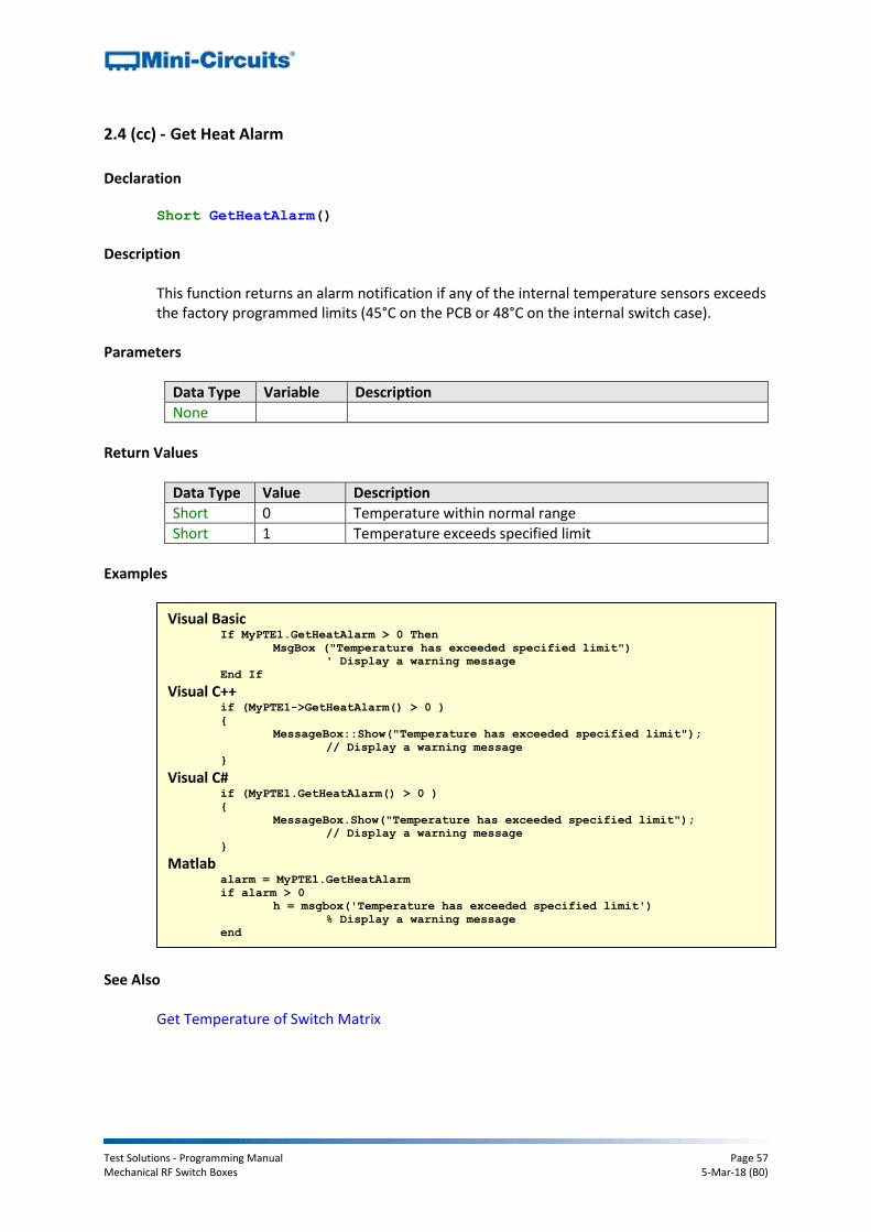
Test Solutions - Programming Manual Page 57 Mechanical RF Switch Boxes 5-Mar-18 (B0)
2.4 (cc) - Get Heat Alarm
Declaration Short GetHeatAlarm()
Description
This function returns an alarm notification if any of the internal temperature sensors exceeds the factory programmed limits (45°C on the PCB or 48°C on the internal switch case).
Parameters
Data Type Variable Description
None
Return Values
Data Type Value Description
Short 0 Temperature within normal range
Short 1 Temperature exceeds specified limit
Examples
See Also
Get Temperature of Switch Matrix
Visual Basic If MyPTE1.GetHeatAlarm > 0 Then
MsgBox ("Temperature has exceeded specified limit")
' Display a warning message
End If Visual C++
if (MyPTE1->GetHeatAlarm() > 0 )
{
MessageBox::Show("Temperature has exceeded specified limit");
// Display a warning message
} Visual C#
if (MyPTE1.GetHeatAlarm() > 0 )
{
MessageBox.Show("Temperature has exceeded specified limit");
// Display a warning message
} Matlab
alarm = MyPTE1.GetHeatAlarm
if alarm > 0
h = msgbox('Temperature has exceeded specified limit')
% Display a warning message
end

Test Solutions - Programming Manual Page 58 Mechanical RF Switch Boxes 5-Mar-18 (B0)
2.4 (dd) - Get 24V DC Supply Status (Antiquated)
Declaration Short Get24V_Indicator()
Description
See Applies To section below. This function checks whether the required 24V DC power supply is connected. If the DC supply is not connected then all SPDT switches will be in the “COM connected to port 1” state and all SP4T switches will be in the “disconnected” state.
Applies To This function is only applicable to the below model and serial number ranges. All subsequent hardware will only communicate when the 24V DC supply is connected so there is no reason to perform an additional check.
Model Serial Numbers
USB-1SPDT-A18 From 11210140015 to 11309160000
USB-2SPDT-A18 From 11010030072 to 11311270000
USB-3SPDT-A18 From 11210140041 to 11403130000
USB-4SPDT-A18 From 11210090035 to 11210090049 and from 11210170001 to 11310100000
USB-8SPDT-A18 From 11210150051 to 11309290000
USB-1SP4T-A18 All serial numbers up to 11310100000
Parameters
Data Type Variable Description
None
Return Values
Data Type Value Description
Short 0 24V DC supply not connected
Short 1 24V DC supply is connected
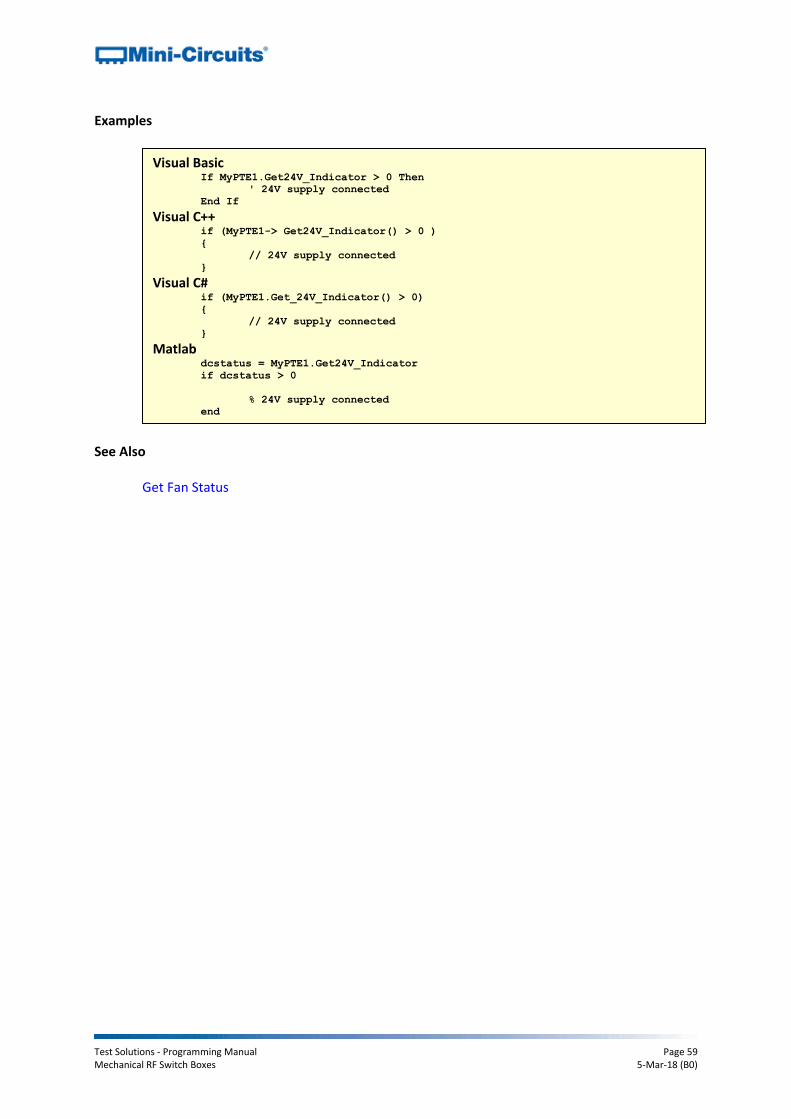
Test Solutions - Programming Manual Page 59 Mechanical RF Switch Boxes 5-Mar-18 (B0)
Examples
See Also Get Fan Status
Visual Basic If MyPTE1.Get24V_Indicator > 0 Then
' 24V supply connected
End If Visual C++
if (MyPTE1-> Get24V_Indicator() > 0 )
{
// 24V supply connected
} Visual C#
if (MyPTE1.Get_24V_Indicator() > 0)
{
// 24V supply connected
} Matlab
dcstatus = MyPTE1.Get24V_Indicator
if dcstatus > 0
% 24V supply connected
end

Test Solutions - Programming Manual Page 60 Mechanical RF Switch Boxes 5-Mar-18 (B0)
2.4 (ee) - Get Fan Status
Declaration Short Get_FAN_Indicator()
Description
This function checks whether the internal fan is currently operating (model dependent). Applies To
Model Serial Numbers
USB-2SPDT-A18 From 11108010000
USB-3SPDT-A18 From 11108010000
USB-4SPDT-A18 From 11108010000
USB-8SPDT-A18 From 11108010000
All other models All serial numbers
Return Values
Data Type Value Description
Short 0 Fan not currently operating
Short 1 Fan operating
Examples
See Also
Check Internal Temperature Get Heat Alarm
Visual Basic If MyPTE1.Get_FAN_Indicator > 0 Then
' Fan is currently operating
End If Visual C++
if (MyPTE1-> Get_FAN_Indicator() > 0 )
{
// Fan is currently operating
} Visual C#
if (MyPTE1.Get_FAN_Indicator() > 0)
{
// Fan is currently operating
} Matlab
fanstatus = MyPTE1.Get_FAN_Indicator
if fanstatus >
% Fan is currently operating
end
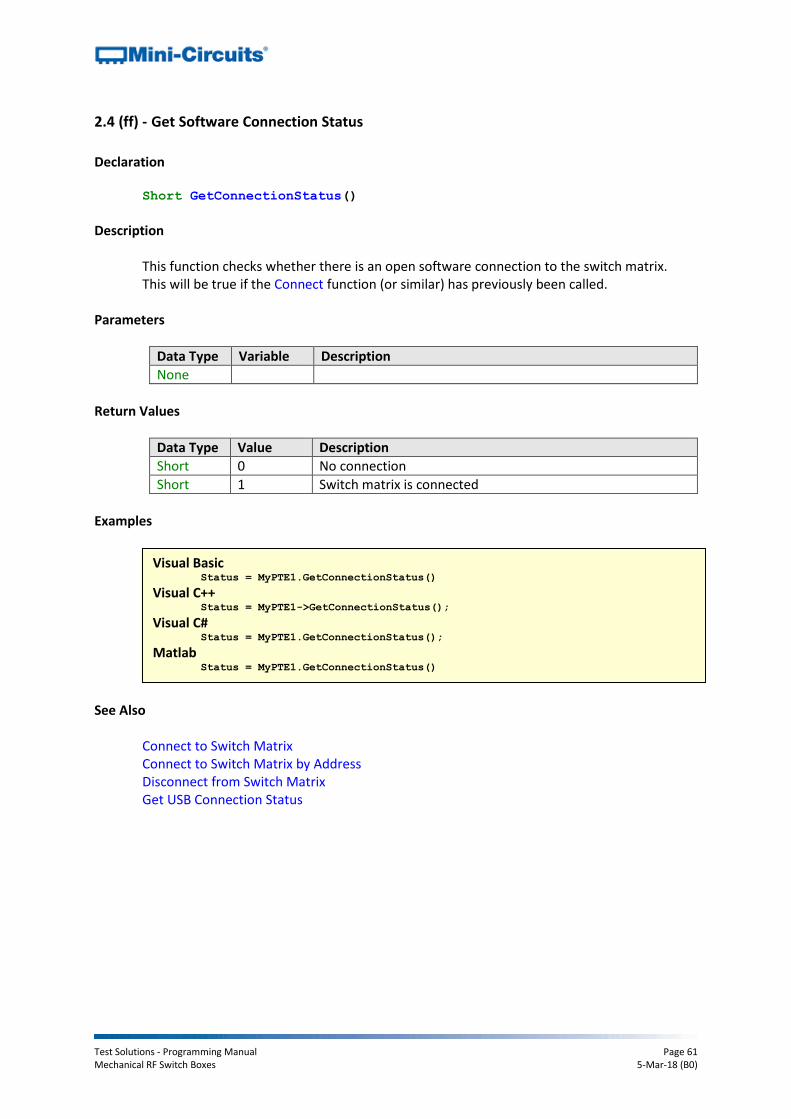
Test Solutions - Programming Manual Page 61 Mechanical RF Switch Boxes 5-Mar-18 (B0)
2.4 (ff) - Get Software Connection Status
Declaration Short GetConnectionStatus()
Description
This function checks whether there is an open software connection to the switch matrix. This will be true if the Connect function (or similar) has previously been called.
Parameters
Data Type Variable Description
None
Return Values
Data Type Value Description
Short 0 No connection
Short 1 Switch matrix is connected
Examples
See Also Connect to Switch Matrix Connect to Switch Matrix by Address Disconnect from Switch Matrix Get USB Connection Status
Visual Basic Status = MyPTE1.GetConnectionStatus()
Visual C++ Status = MyPTE1->GetConnectionStatus();
Visual C# Status = MyPTE1.GetConnectionStatus();
Matlab Status = MyPTE1.GetConnectionStatus()
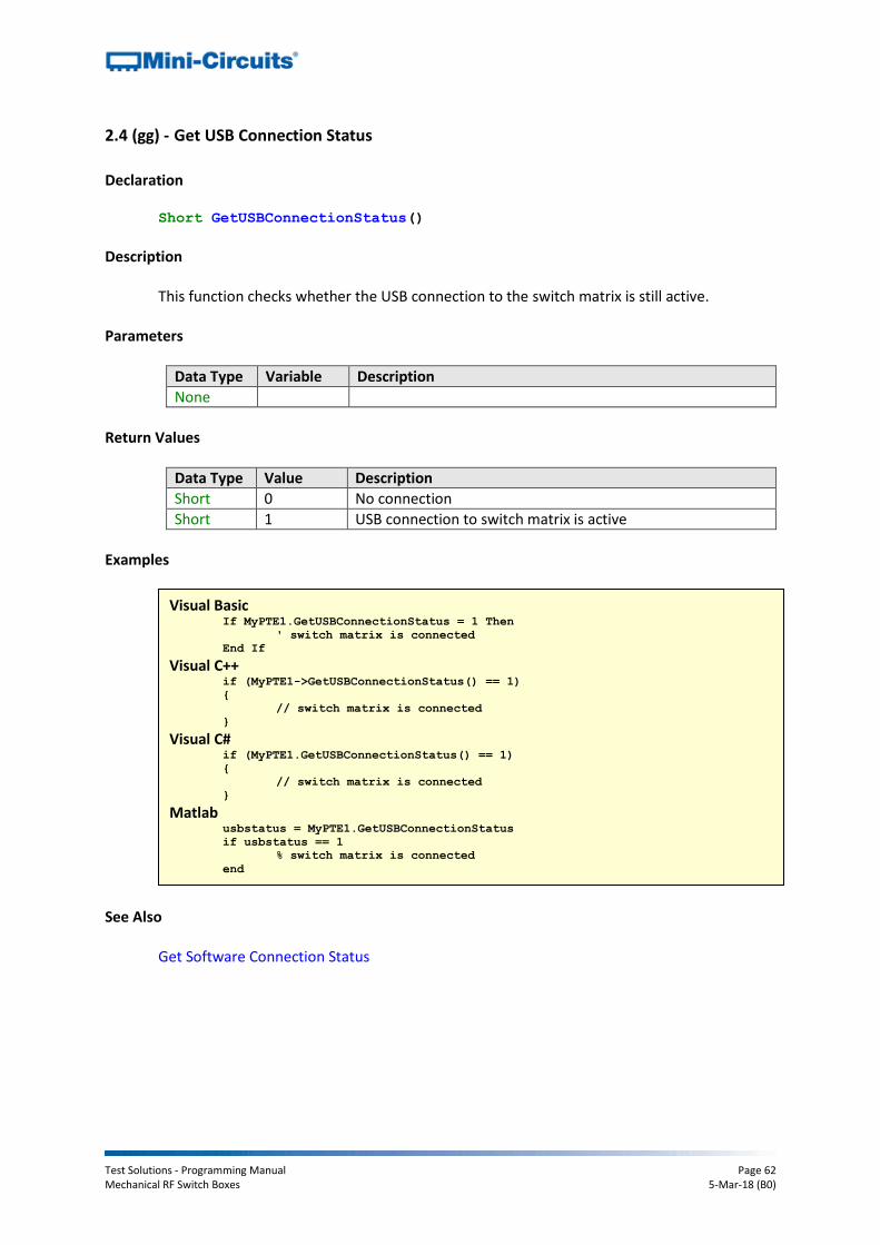
Test Solutions - Programming Manual Page 62 Mechanical RF Switch Boxes 5-Mar-18 (B0)
2.4 (gg) - Get USB Connection Status
Declaration Short GetUSBConnectionStatus()
Description
This function checks whether the USB connection to the switch matrix is still active. Parameters
Data Type Variable Description
None
Return Values
Data Type Value Description
Short 0 No connection
Short 1 USB connection to switch matrix is active
Examples
See Also Get Software Connection Status
Visual Basic If MyPTE1.GetUSBConnectionStatus = 1 Then
' switch matrix is connected
End If Visual C++
if (MyPTE1->GetUSBConnectionStatus() == 1)
{
// switch matrix is connected
} Visual C#
if (MyPTE1.GetUSBConnectionStatus() == 1)
{
// switch matrix is connected
} Matlab
usbstatus = MyPTE1.GetUSBConnectionStatus
if usbstatus == 1
% switch matrix is connected
end

Test Solutions - Programming Manual Page 63 Mechanical RF Switch Boxes 5-Mar-18 (B0)
2.4 (hh) - Check Connection (Antiquated)
Declaration Short Check_Connection()
Description
This function is antiquated, GetUSBConnectionStatus should be used instead. The function checks whether the USB connection to the switch matrix is still active.
Parameters
Data Type Variable Description
None
Return Values
Data Type Value Description
Short 0 No connection
Short 1 USB connection to switch matrix is active
See Also Get Software Connection Status

Test Solutions - Programming Manual Page 64 Mechanical RF Switch Boxes 5-Mar-18 (B0)
2.4 (ii) - Get USB Device Name
Declaration String GetUSBDeviceName()
Description
This function is for advanced users to identify the USB device name of the switch matrix for direct communication.
Parameters
Data Type Variable Description
None
Return Values
Data Type Value Description
String Name Device name of the switch matrix
Examples
Visual Basic usbname = MyPTE1.GetUSBDeviceName()
' Return the USB device name as a string Visual C++
usbname = MyPTE1->GetUSBDeviceName();
// Return the USB device name as a string Visual C#
usbname = MyPTE1.GetUSBDeviceName();
// Return the USB device name as a string Matlab
usbname = MyPTE1.GetUSBDeviceName
% Return the USB device name as a string

Test Solutions - Programming Manual Page 65 Mechanical RF Switch Boxes 5-Mar-18 (B0)
2.4 (jj) - Get Firmware
Declaration Short GetExtFirmware(Short A0, Short A1, Short A2, Short A3,
String Firmware)
Description
This function returns the internal firmware version of the switch matrix along with three reserved variables (for factory use).
Parameters
Data Type Variable Description
Short A0 Required. User defined variable for factory use only.
Short A1 Required. User defined variable for factory use only.
Short A2 Required. User defined variable for factory use only.
Short A3 Required. User defined variable for factory use only.
String Firmware Required. User defined variable which will be updated with the current firmware version, for example “B3”.
Return Values
Data Type Value Description
Short 0 Command failed
Short 1 Command completed successfully
Examples
Visual Basic If MyPTE1.GetExtFirmware(A0, A1, A2, A3, Firmware) > 0 Then
MsgBox ("Firmware version is " & Firmware)
End If Visual C++
if (MyPTE1->GetExtFirmware(A0, A1, A2, A3, Firmware) > 0 )
{
MessageBox::Show("Firmware version is " + Firmware);
} Visual C#
if (MyPTE1.GetExtFirmware(ref(A0, A1, A2, A3, Firmware)) > 0 )
{
MessageBox.Show("Firmware version is " + Firmware);
} Matlab
[status, A0, A1, A2, A3, Firmware]
= MyPTE1.GetExtFirmware(A0, A1, A2, A3, Firmware)
if status > 0
msgbox('Firmware version is ', Firmware)
end
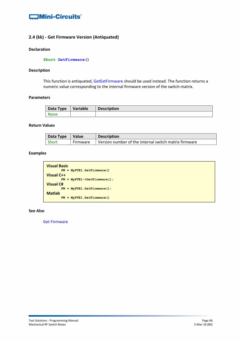
Test Solutions - Programming Manual Page 66 Mechanical RF Switch Boxes 5-Mar-18 (B0)
2.4 (kk) - Get Firmware Version (Antiquated)
Declaration Short GetFirmware()
Description
This function is antiquated, GetExtFirmware should be used instead. The function returns a numeric value corresponding to the internal firmware version of the switch matrix.
Parameters
Data Type Variable Description
None
Return Values
Data Type Value Description
Short Firmware Version number of the internal switch matrix firmware
Examples
See Also
Get Firmware
Visual Basic FW = MyPTE1.GetFirmware()
Visual C++ FW = MyPTE1->GetFirmware();
Visual C# FW = MyPTE1.GetFirmware();
Matlab FW = MyPTE1.GetFirmware()

Test Solutions - Programming Manual Page 67 Mechanical RF Switch Boxes 5-Mar-18 (B0)
2.5 - DLL Functions for Ethernet Configuration These functions apply to the Mini-Circuits “RC” series of switch matrix models with an Ethernet interface (RJ45 connector). The functions provide a means for identifying or configuring the Ethernet settings such as IP address, TCP/IP port and network gateway. They can only be called while the devices are connected via the USB interface.
2.5 (a) - Get Ethernet Configuration
Declaration Short GetEthernet_CurrentConfig(Int IP1, Int IP2, Int IP3, Int IP4,
Int Mask1, Int Mask2, Int Mask3, Int Mask4,
Int Gateway1, Int Gateway2, Int Gateway3, Int Gateway4)
Description
This function returns the current IP configuration of the connected switch matrix in a series of user defined variables. The settings checked are IP address, subnet mask and network gateway.
Parameters
Data Type Variable Description
Int IP1 Required. Integer variable which will be updated with the first (highest order) octet of the IP address.
Int IP2 Required. Integer variable which will be updated with the second octet of the IP address.
Int IP2 Required. Integer variable which will be updated with the third octet of the IP address.
Int IP4 Required. Integer variable which will be updated with the last (lowest order) octet of the IP address.
Int Mask1 Required. Integer variable which will be updated with the first (highest order) octet of the subnet mask.
Int Mask2 Required. Integer variable which will be updated with the second octet of the subnet mask.
Int Mask3 Required. Integer variable which will be updated with the third octet of the subnet mask.
Int Mask4 Required. Integer variable which will be updated with the last (lowest order) octet of the subnet mask.
Int Gateway1 Required. Integer variable which will be updated with the first (highest order) octet of the subnet mask.
Int Gateway2 Required. Integer variable which will be updated with the second octet of the network gateway.
Int Gateway3 Required. Integer variable which will be updated with the third octet of the network gateway.
Int Gateway4 Required. Integer variable which will be updated with the last (lowest order) octet of the network gateway.

Test Solutions - Programming Manual Page 68 Mechanical RF Switch Boxes 5-Mar-18 (B0)
Return Values
Data Type Value Description
Short 0 Command failed
Short 1 Command completed successfully
Example
See Also
Get MAC Address Get TCP/IP Port
Visual Basic If MyPTE1.GetEthernet_CurrentConfig(IP1, IP2, IP3, IP4, M1, M2, M3, M4,
_ GW1, GW2, GW3, GW4) > 0 Then
MsgBox ("IP address: " & IP1 & "." & IP2 & "." & IP3 & "." & IP4)
MsgBox ("Subnet Mask: " & M1 & "." & M2 & "." & M3 & "." & M4)
MsgBox ("Gateway: " & GW1 & "." & GW2 & "." & GW3 & "." & GW4)
End If
Visual C++ if (MyPTE1->GetEthernet_CurrentConfig(IP1, IP2, IP3, IP4, M1, M2, M3, M4,
_ GW1, GW2, GW3, GW4) > 0)
{
MessageBox::Show("IP address: " + IP1 + "." + IP2 + "." + IP3 + "."
_ + IP4);
MessageBox::Show("Subnet Mask: " + M1 + "." + M2 + "." + M3+ "." +
_ M4);
MessageBox::Show("Gateway: " + GW1 + "." + GW2 + "." + GW3 + "." +
_ GW4);
} Visual C#
if (MyPTE1.GetEthernet_CurrentConfig(IP1, IP2, IP3, IP4, M1, M2, M3, M4,
_ GW1, GW2, GW3, GW4) > 0)
{
MessageBox.Show("IP address: " + IP1 + "." + IP2 + "." + IP3 + "."
_ + IP4);
MessageBox.Show("Subnet Mask: " + M1 + "." + M2 + "." + M3+ "." +
_ M4);
MessageBox.Show("Gateway: " + GW1 + "." + GW2 + "." + GW3 + "." +
_ GW4);
} Matlab
[status, IP1, IP2, IP3, IP4, M1, M2, M3, M4, GW1, GW2, GW3, GW4] =
MyPTE1.GetEthernet_CurrentConfig(IP1, IP2, IP3, IP4, M1, M2, M3, M4, GW1,
GW2, GW3, GW4)
if status > 0
h = msgbox ("IP address: ", IP1, ".", IP2, ".", IP3, ".", IP4)
h = msgbox ("Subnet Mask: ", M1, "." & M2, "." & M3, ".", M4)
h = msgbox ("Gateway: ", GW1, ".", GW2, ".", GW3, ".", GW4)
end

Test Solutions - Programming Manual Page 69 Mechanical RF Switch Boxes 5-Mar-18 (B0)
2.5 (b) - Get IP Address
Declaration Short GetEthernet_IPAddress(Int b1, Int b2, Int b3, Int b4)
Description
This function returns the current IP address of the connected switch matrix in a series of user defined variables (one per octet).
Parameters
Data Type Variable Description
Int IP1 Required. Integer variable which will be updated with the first (highest order) octet of the IP address (for example “192” for the IP address “192.168.1.0”).
Int IP2 Required. Integer variable which will be updated with the second octet of the IP address (for example “168” for the IP address “192.168.1.0”).
Int IP2 Required. Integer variable which will be updated with the third octet of the IP address (for example “1” for the IP address “192.168.1.0”).
Int IP4 Required. Integer variable which will be updated with the last (lowest order) octet of the IP address (for example “0” for the IP address “192.168.1.0”).
Return Values
Data Type Value Description
Short 0 Command failed
Short 1 Command completed successfully
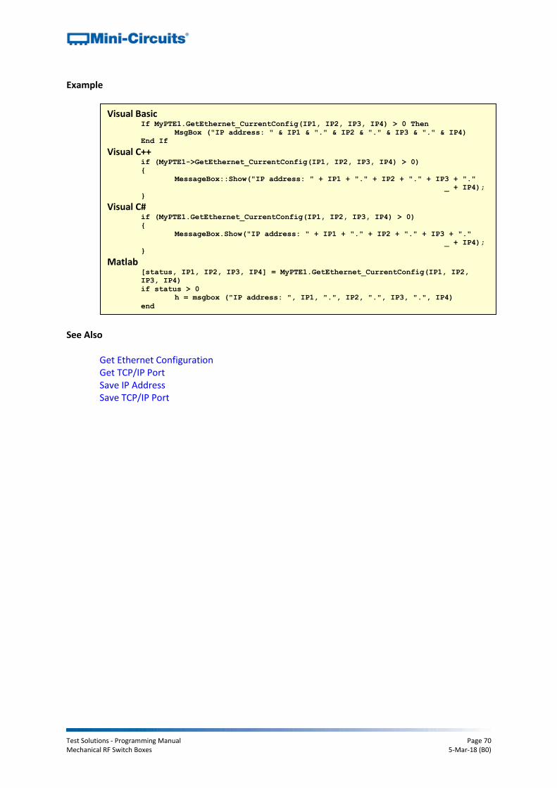
Test Solutions - Programming Manual Page 70 Mechanical RF Switch Boxes 5-Mar-18 (B0)
Example
See Also
Get Ethernet Configuration Get TCP/IP Port Save IP Address Save TCP/IP Port
Visual Basic If MyPTE1.GetEthernet_CurrentConfig(IP1, IP2, IP3, IP4) > 0 Then
MsgBox ("IP address: " & IP1 & "." & IP2 & "." & IP3 & "." & IP4)
End If
Visual C++ if (MyPTE1->GetEthernet_CurrentConfig(IP1, IP2, IP3, IP4) > 0)
{
MessageBox::Show("IP address: " + IP1 + "." + IP2 + "." + IP3 + "."
_ + IP4);
} Visual C#
if (MyPTE1.GetEthernet_CurrentConfig(IP1, IP2, IP3, IP4) > 0)
{
MessageBox.Show("IP address: " + IP1 + "." + IP2 + "." + IP3 + "."
_ + IP4);
} Matlab
[status, IP1, IP2, IP3, IP4] = MyPTE1.GetEthernet_CurrentConfig(IP1, IP2,
IP3, IP4)
if status > 0
h = msgbox ("IP address: ", IP1, ".", IP2, ".", IP3, ".", IP4)
end

Test Solutions - Programming Manual Page 71 Mechanical RF Switch Boxes 5-Mar-18 (B0)
2.5 (c) - Get MAC Address
Declaration Short GetEthernet_MACAddress(Int MAC1, Int MAC2, Int MAC3, Int MAC4,
Int MAC5, Int MAC6)
Description
This function returns the MAC (media access control) address, the physical address, of the connected switch matrix as a series of decimal values (one for each of the 6 numeric groups).
Parameters
Data Type Variable Description
Int MAC1 Required. Integer variable which will be updated with the decimal value of the first numeric group of the MAC address. For example: MAC address =11:47:165:103:137:171 MAC1=11
Int MAC2 Required. Integer variable which will be updated with the decimal value of the second numeric group of the MAC address. For example: MAC address =11:47:165:103:137:171 MAC2=47
Int MAC3 Required. Integer variable which will be updated with the decimal value of the third numeric group of the MAC address. For example: MAC address =11:47:165:103:137:171 MAC3=165
Int MAC4 Required. Integer variable which will be updated with the decimal value of the fourth numeric group of the MAC address. For example: MAC address =11:47:165:103:137:171 MAC4=103
Int MAC5 Required. Integer variable which will be updated with the decimal value of the fifth numeric group of the MAC address. For example: MAC address =11:47:165:103:137:171 MAC5=137
Int MAC6 Required. Integer variable which will be updated with the decimal value of the last numeric group of the MAC address. For example: MAC address =11:47:165:103:137:171 MAC6=171

Test Solutions - Programming Manual Page 72 Mechanical RF Switch Boxes 5-Mar-18 (B0)
Return Values
Data Type Value Description
Short 0 Command failed
Short 1 Command completed successfully
Example
See Also
Get Ethernet Configuration
Visual Basic If MyPTE1.GetEthernet_MACAddess(M1, M2, M3, M4, M5, M6) > 0 Then
MsgBox ("MAC address: " & M1 & ":" & M2 & ":" & M3 & ":" & M4 & ":"
_ & M5 & ":" & M6)
End If
Visual C++ if (MyPTE1->GetEthernet_MACAddess(M1, M2, M3, M4, M5, M6) > 0)
{
MessageBox::Show("MAC address: " + M1 + "." + M2 + "." + M3 + "."
_ + M4 + "." + M5 + "." + M6);
} Visual C#
if (MyPTE1.GetEthernet_MACAddess(M1, M2, M3, M4, M5, M6) > 0)
{
MessageBox.Show("MAC address: " + M1 + "." + M2 + "." + M3 + "."
_ + M4 + "." + M5 + "." + M6);
} Matlab
[status, M1, M2, M3, M4, M5, M6] = MyPTE1.GetEthernet_MACAddess(M1, M2, M3,
M4, M5, M6)
if status > 0
h = msgbox ("MAC address: ", M1, ".", M2, ".", M3, ".", M4, ".", M5,
".", M6)
end
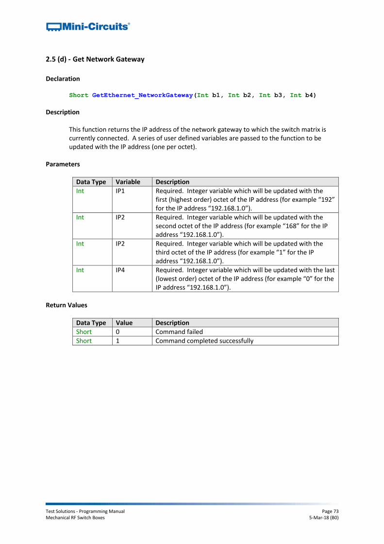
Test Solutions - Programming Manual Page 73 Mechanical RF Switch Boxes 5-Mar-18 (B0)
2.5 (d) - Get Network Gateway
Declaration Short GetEthernet_NetworkGateway(Int b1, Int b2, Int b3, Int b4)
Description
This function returns the IP address of the network gateway to which the switch matrix is currently connected. A series of user defined variables are passed to the function to be updated with the IP address (one per octet).
Parameters
Data Type Variable Description
Int IP1 Required. Integer variable which will be updated with the first (highest order) octet of the IP address (for example “192” for the IP address “192.168.1.0”).
Int IP2 Required. Integer variable which will be updated with the second octet of the IP address (for example “168” for the IP address “192.168.1.0”).
Int IP2 Required. Integer variable which will be updated with the third octet of the IP address (for example “1” for the IP address “192.168.1.0”).
Int IP4 Required. Integer variable which will be updated with the last (lowest order) octet of the IP address (for example “0” for the IP address “192.168.1.0”).
Return Values
Data Type Value Description
Short 0 Command failed
Short 1 Command completed successfully

Test Solutions - Programming Manual Page 74 Mechanical RF Switch Boxes 5-Mar-18 (B0)
Example
See Also
Get Ethernet Configuration Save Network Gateway
Visual Basic If MyPTE1.GetEthernet_NetworkGateway(IP1, IP2, IP3, IP4) > 0 Then
MsgBox ("Gateway: " & IP1 & "." & IP2 & "." & IP3 & "." & IP4)
End If
Visual C++ if (MyPTE1->GetEthernet_NetworkGateway(IP1, IP2, IP3, IP4) > 0)
{
MessageBox::Show("Gateway: " + IP1 + "." + IP2 + "." + IP3 + "."
_ + IP4);
} Visual C#
if (MyPTE1.GetEthernet_NetworkGateway(IP1, IP2, IP3, IP4) > 0)
{
MessageBox.Show("Gateway: " + IP1 + "." + IP2 + "." + IP3 + "."
_ + IP4);
} Matlab
[status, IP1, IP2, IP3, IP4] = MyPTE1.GetEthernet_NetworkGateway(IP1, IP2,
IP3, IP4)
if status > 0
h = msgbox ("Gateway: ", IP1, ".", IP2, ".", IP3, ".", IP4)
end

Test Solutions - Programming Manual Page 75 Mechanical RF Switch Boxes 5-Mar-18 (B0)
2.5 (e) - Get Subnet Mask
Declaration Short GetEthernet_SubNetMask(Int b1, Int b2, Int b3, Int b4)
Description
This function returns the subnet mask used by the network gateway to which the switch matrix is currently connected. A series of user defined variables are passed to the function to be updated with the subnet mask (one per octet).
Parameters
Data Type Variable Description
Int b1 Required. Integer variable which will be updated with the first (highest order) octet of the subnet mask (for example “255” for the subnet mask “255.255.255.0”).
Int b2 Required. Integer variable which will be updated with the second octet of the subnet mask (for example “255” for the subnet mask “255.255.255.0”).
Int b2 Required. Integer variable which will be updated with the third octet of the subnet mask (for example “255” for the subnet mask “255.255.255.0”).
Int b4 Required. Integer variable which will be updated with the last (lowest order) octet of the subnet mask (for example “0” for the subnet mask “255.255.255.0”).
Return Values
Data Type Value Description
Short 0 Command failed
Short 1 Command completed successfully

Test Solutions - Programming Manual Page 76 Mechanical RF Switch Boxes 5-Mar-18 (B0)
Example
See Also
Get Ethernet Configuration Save Subnet Mask
Visual Basic If MyPTE1.GetEthernet_SubNetMask(b1, b2, b3, b4) > 0 Then
MsgBox ("Subnet mask: " & b1 & "." & b2 & "." & b3 & "." & b4)
End If
Visual C++ if (MyPTE1->GetEthernet_SubNetMask(b1, b2, b3, b4) > 0)
{
MessageBox::Show("Subnet mask: " + b1 + "." + b2 + "." + b3 + "."
_ + b4);
} Visual C#
if (MyPTE1.GetEthernet_SubNetMask(b1, b2, b3, b4) > 0)
{
MessageBox.Show("Subnet mask: " + b1 + "." + b2 + "." + b3 + "."
_ + b4);
} Matlab
[status, b1, b2, b3, b4] = MyPTE1.GetEthernet_SubNetMask(b1, b2, b3, b4)
if status > 0
h = msgbox ("Subnet mask: ", b1, ".", b2, ".", b3, ".", b4)
end

Test Solutions - Programming Manual Page 77 Mechanical RF Switch Boxes 5-Mar-18 (B0)
2.5 (f) - Get TCP/IP Port
Declaration Short GetEthernet_TCPIPPort(Int port)
Description
This function returns the TCP/IP port used by the switch matrix for HTTP communication. The default is port 80. Note: Port 23 is reserved for Telnet communication and cannot be set as the HTTP port.
Parameters
Data Type Variable Description
Int port Required. Integer variable which will be updated with the TCP/IP port.
Return Values
Data Type Value Description
Short 0 Command failed
Short 1 Command completed successfully
Example
See Also
Get Ethernet Configuration Save TCP/IP Port
Visual Basic If MyPTE1.GetEthernet_SubNetMask(port) > 0 Then
MsgBox ("Port: " & port)
End If
Visual C++ if (MyPTE1->GetEthernet_SubNetMask(port) > 0)
{
MessageBox::Show("Port: " + port);
} Visual C#
if (MyPTE1.GetEthernet_SubNetMask(port) > 0)
{
MessageBox.Show("Port: " + port);
} Matlab
[status, port] = MyPTE1.GetEthernet_SubNetMask(port)
if status > 0
h = msgbox ("Port: ", port)
end
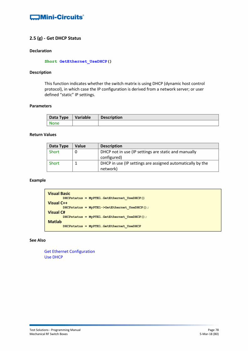
Test Solutions - Programming Manual Page 78 Mechanical RF Switch Boxes 5-Mar-18 (B0)
2.5 (g) - Get DHCP Status
Declaration Short GetEthernet_UseDHCP()
Description
This function indicates whether the switch matrix is using DHCP (dynamic host control protocol), in which case the IP configuration is derived from a network server; or user defined “static” IP settings.
Parameters
Data Type Variable Description
None
Return Values
Data Type Value Description
Short 0 DHCP not in use (IP settings are static and manually configured)
Short 1 DHCP in use (IP settings are assigned automatically by the network)
Example
See Also
Get Ethernet Configuration Use DHCP
Visual Basic DHCPstatus = MyPTE1.GetEthernet_UseDHCP()
Visual C++ DHCPstatus = MyPTE1->GetEthernet_UseDHCP();
Visual C# DHCPstatus = MyPTE1.GetEthernet_UseDHCP();
Matlab DHCPstatus = MyPTE1.GetEthernet_UseDHCP

Test Solutions - Programming Manual Page 79 Mechanical RF Switch Boxes 5-Mar-18 (B0)
2.5 (h) - Get Password Status
Declaration Short GetEthernet_UsePWD()
Description
This function indicates whether the switch matrix is currently configured to require a password for HTTP/Telnet communication.
Parameters
Data Type Variable Description
None
Return Values
Data Type Value Description
Short 0 Password not required
Short 1 Password required
Example
See Also
Get Password Use Password Set Password
Visual Basic PWDstatus = MyPTE1.GetEthernet_UsePWD()
Visual C++ PWDstatus = MyPTE1->GetEthernet_UsePWD();
Visual C# PWDstatus = MyPTE1.GetEthernet_UsePWD();
Matlab PWDstatus = MyPTE1.GetEthernet_UsePWD

Test Solutions - Programming Manual Page 80 Mechanical RF Switch Boxes 5-Mar-18 (B0)
2.5 (i) - Get Password
Declaration Short GetEthernet_PWD(String Pwd)
Description
This function returns the current password used by the switch matrix for HTTP/Telnet communication. The password will be returned even if the device is not currently configured to require a password.
Parameters
Data Type Variable Description
String Pwd Required. String variable which will be updated with the password.
Return Values
Data Type Value Description
Short 0 Command failed
Short 1 Command completed successfully
Example
See Also
Get Password Status Use Password Set Password
Visual Basic If MyPTE1.GetEthernet_PWD(pwd) > 0 Then
MsgBox ("Password: " & pwd)
End If
Visual C++ if (MyPTE1->GetEthernet_PWD(pwd) > 0)
{
MessageBox::Show("Password: " + pwd);
} Visual C#
if (MyPTE1.GetEthernet_PWD(pwd) > 0)
{
MessageBox.Show("Password: " + pwd);
} Matlab
[status, pwd] = MyPTE1.GetEthernet_PWD(pwd)
if status > 0
h = msgbox ("Password: ", pwd)
end
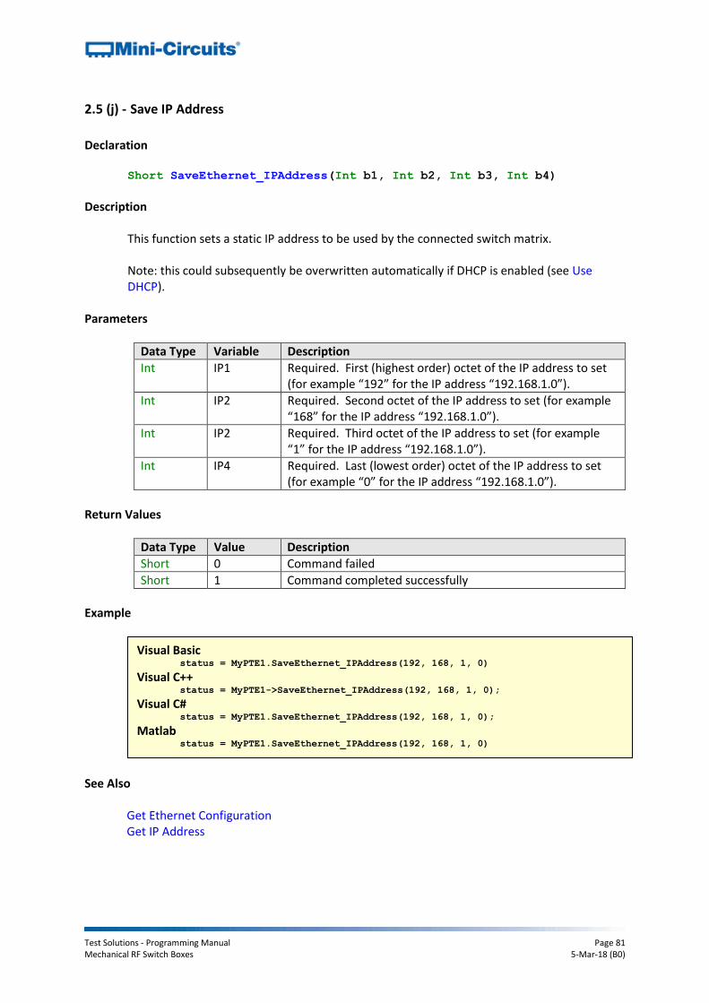
Test Solutions - Programming Manual Page 81 Mechanical RF Switch Boxes 5-Mar-18 (B0)
2.5 (j) - Save IP Address
Declaration Short SaveEthernet_IPAddress(Int b1, Int b2, Int b3, Int b4)
Description
This function sets a static IP address to be used by the connected switch matrix. Note: this could subsequently be overwritten automatically if DHCP is enabled (see Use DHCP).
Parameters
Data Type Variable Description
Int IP1 Required. First (highest order) octet of the IP address to set (for example “192” for the IP address “192.168.1.0”).
Int IP2 Required. Second octet of the IP address to set (for example “168” for the IP address “192.168.1.0”).
Int IP2 Required. Third octet of the IP address to set (for example “1” for the IP address “192.168.1.0”).
Int IP4 Required. Last (lowest order) octet of the IP address to set (for example “0” for the IP address “192.168.1.0”).
Return Values
Data Type Value Description
Short 0 Command failed
Short 1 Command completed successfully
Example
See Also
Get Ethernet Configuration Get IP Address
Visual Basic status = MyPTE1.SaveEthernet_IPAddress(192, 168, 1, 0)
Visual C++ status = MyPTE1->SaveEthernet_IPAddress(192, 168, 1, 0);
Visual C# status = MyPTE1.SaveEthernet_IPAddress(192, 168, 1, 0);
Matlab status = MyPTE1.SaveEthernet_IPAddress(192, 168, 1, 0)

Test Solutions - Programming Manual Page 82 Mechanical RF Switch Boxes 5-Mar-18 (B0)
2.5 (k) - Save Network Gateway
Declaration Short SaveEthernet_NetworkGateway(Int b1, Int b2, Int b3, Int b4)
Description
This function sets the IP address of the network gateway to which the switch matrix should connect. Note: this could subsequently be overwritten automatically if DHCP is enabled (see Use DHCP).
Parameters
Data Type Variable Description
Int IP1 Required. First (highest order) octet of the network gateway IP address (for example “192” for the IP address “192.168.1.0”).
Int IP2 Required. Second octet of the network gateway IP address (for example “168” for the IP address “192.168.1.0”).
Int IP2 Required. Third octet of the network gateway IP address (for example “1” for the IP address “192.168.1.0”).
Int IP4 Required. Last (lowest order) octet of the network gateway IP address (for example “0” for the IP address “192.168.1.0”).
Return Values
Data Type Value Description
Short 0 Command failed
Short 1 Command completed successfully
Example
See Also
Get Ethernet Configuration Get Network Gateway
Visual Basic status = MyPTE1.SaveEthernet_NetworkGateway(192, 168, 1, 0)
Visual C++ status = MyPTE1->SaveEthernet_NetworkGateway(192, 168, 1, 0);
Visual C# status = MyPTE1.SaveEthernet_NetworkGateway(192, 168, 1, 0);
Matlab status = MyPTE1.SaveEthernet_NetworkGateway(192, 168, 1, 0)
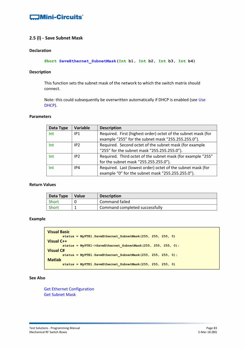
Test Solutions - Programming Manual Page 83 Mechanical RF Switch Boxes 5-Mar-18 (B0)
2.5 (l) - Save Subnet Mask
Declaration Short SaveEthernet_SubnetMask(Int b1, Int b2, Int b3, Int b4)
Description
This function sets the subnet mask of the network to which the switch matrix should connect. Note: this could subsequently be overwritten automatically if DHCP is enabled (see Use DHCP).
Parameters
Data Type Variable Description
Int IP1 Required. First (highest order) octet of the subnet mask (for example “255” for the subnet mask “255.255.255.0”).
Int IP2 Required. Second octet of the subnet mask (for example “255” for the subnet mask “255.255.255.0”).
Int IP2 Required. Third octet of the subnet mask (for example “255” for the subnet mask “255.255.255.0”).
Int IP4 Required. Last (lowest order) octet of the subnet mask (for example “0” for the subnet mask “255.255.255.0”).
Return Values
Data Type Value Description
Short 0 Command failed
Short 1 Command completed successfully
Example
See Also
Get Ethernet Configuration Get Subnet Mask
Visual Basic status = MyPTE1.SaveEthernet_SubnetMask(255, 255, 255, 0)
Visual C++ status = MyPTE1->SaveEthernet_SubnetMask(255, 255, 255, 0);
Visual C# status = MyPTE1.SaveEthernet_SubnetMask(255, 255, 255, 0);
Matlab status = MyPTE1.SaveEthernet_SubnetMask(255, 255, 255, 0)
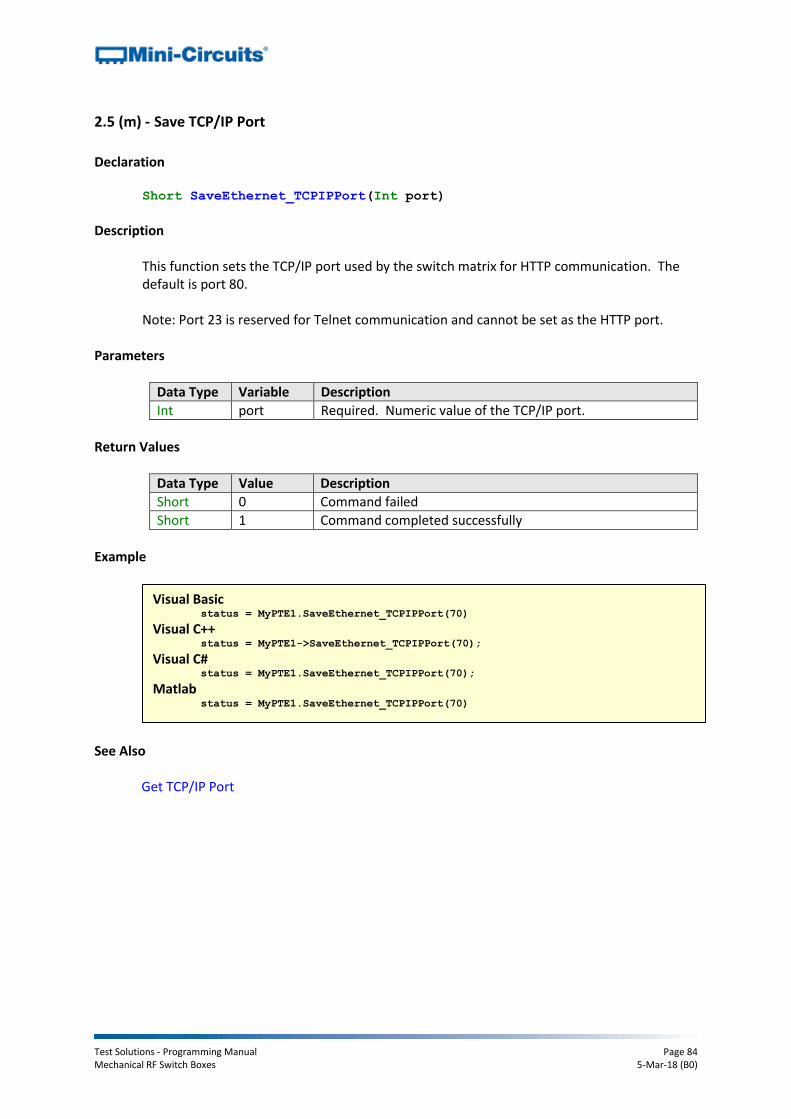
Test Solutions - Programming Manual Page 84 Mechanical RF Switch Boxes 5-Mar-18 (B0)
2.5 (m) - Save TCP/IP Port
Declaration Short SaveEthernet_TCPIPPort(Int port)
Description
This function sets the TCP/IP port used by the switch matrix for HTTP communication. The default is port 80. Note: Port 23 is reserved for Telnet communication and cannot be set as the HTTP port.
Parameters
Data Type Variable Description
Int port Required. Numeric value of the TCP/IP port.
Return Values
Data Type Value Description
Short 0 Command failed
Short 1 Command completed successfully
Example
See Also
Get TCP/IP Port
Visual Basic status = MyPTE1.SaveEthernet_TCPIPPort(70)
Visual C++ status = MyPTE1->SaveEthernet_TCPIPPort(70);
Visual C# status = MyPTE1.SaveEthernet_TCPIPPort(70);
Matlab status = MyPTE1.SaveEthernet_TCPIPPort(70)

Test Solutions - Programming Manual Page 85 Mechanical RF Switch Boxes 5-Mar-18 (B0)
2.5 (n) - Use DHCP
Declaration Short SaveEthernet_UseDHCP(Int UseDHCP)
Description
This function enables or disables DHCP (dynamic host control protocol). When enabled the IP configuration of the switch matrix is assigned automatically by the network server; when disabled the user defined “static” IP settings apply.
Parameters
Data Type Variable Description
Int UseDHCP Required. Integer value to set the DHCP mode: 0 - DHCP disabled (static IP settings used) 1 - DHCP enabled (IP setting assigned by network)
Return Values
Data Type Value Description
Short 0 Command failed
Short 1 Command completed successfully
Example
See Also
Get DHCP Status
Visual Basic status = MyPTE1.SaveEthernet_UseDHCP(1)
Visual C++ status = MyPTE1->SaveEthernet_UseDHCP(1);
Visual C# status = MyPTE1.SaveEthernet_UseDHCP(1);
Matlab status = MyPTE1.SaveEthernet_UseDHCP(1)

Test Solutions - Programming Manual Page 86 Mechanical RF Switch Boxes 5-Mar-18 (B0)
2.5 (o) - Use Password
Declaration Short SaveEthernet_UsePWD(Int UsePwd)
Description
This function enables or disables the password requirement for HTTP/Telnet communication with the switch matrix.
Parameters
Data Type Variable Description
Int UseDHCP Required. Integer value to set the password mode: 0 – Password not required 1 – Password required
Return Values
Data Type Value Description
Short 0 Command failed
Short 1 Command completed successfully
Example
See Also
Get Password Status Get Password Set Password
Visual Basic status = MyPTE1.SaveEthernet_UsePWD(1)
Visual C++ status = MyPTE1->SaveEthernet_UsePWD(1);
Visual C# status = MyPTE1.SaveEthernet_UsePWD(1);
Matlab status = MyPTE1.SaveEthernet_UsePWD(1)

Test Solutions - Programming Manual Page 87 Mechanical RF Switch Boxes 5-Mar-18 (B0)
2.5 (p) - Set Password
Declaration Short SaveEthernet_PWD(String Pwd)
Description
This function sets the password used by the switch matrix for HTTP/Telnet communication. The password will not affect switch operation unless Use Password is also enabled.
Parameters
Data Type Variable Description
String Pwd Required. The password to set (20 characters maximum).
Return Values
Data Type Value Description
Short 0 Command failed
Short 1 Command completed successfully
Example
See Also
Get Password Status Get Password Use Password
Visual Basic status = MyPTE1.SaveEthernet_PWD("123")
Visual C++ status = MyPTE1->SaveEthernet_PWD("123");
Visual C# status = MyPTE1.SaveEthernet_PWD("123");
Matlab status = MyPTE1.SaveEthernet_PWD("123")
Test Solutions - Programming Manual Page 88 Mechanical RF Switch Boxes 5-Mar-18 (B0)
3 - Operating in a Linux Environment via USB
To open a USB connection to the Mini-Circuits RF switch matrix series, the Vendor ID and Product ID are required:
Mini-Circuits Vendor ID: 0x20CE
Switch Matrix Product ID: 0x22 Communication with the switch matrix is carried out by way of USB Interrupt. The transmitted and received buffer sizes are 64 Bytes each:
Transmit Array = [Byte 0][Byte1][Byte2]…[Byte 63]
Returned Array = [Byte 0][Byte1][Byte2]…[Byte 63] In most cases, the full 64 byte buffer size is not needed so any unused bytes become “don’t care” bytes; they can take on any value without affecting the operation of the switch matrix. A worked example is included in Programming Examples & Troubleshooting. The example uses the libhid and libusb libraries to interface with the switch matrix as a USB HID (Human Interface Device).

Test Solutions - Programming Manual Page 89 Mechanical RF Switch Boxes 5-Mar-18 (B0)
3.1 - Core Commands / Queries
The commands that can be sent to the switch matrix are summarized in the table below and detailed on the following pages.
Description Command
Code (Byte 0) Comments
a Get Device Model Name 40
b Get Device Serial Number 41
c Set Single SPDT / Transfer Switch
1
2
3
4
5
6
7
8
Switch A
Switch B
Switch C
Switch D
Switch E
Switch F
Switch G
Switch H
d Set All SPDT / Transfer Switches 9
e Set All SP4T Switches 9
f Set SP6T Switch 12
g Get All SPDT / Transfer Switch States 15
h Get All SP4T Switch States 15
i Get SP6T Switch State 13
j Set Power-Up Mode 89
k Get Power-UP Mode 90
l Get Firmware 99
m Check Internal Temperature
114
115
118
Sensor 1
Sensor 2
Sensor 3
n Get 24V DC Power Indicator 116
o Get Heat Alarm 117
p Get Fan Status 119
q Get Switch Counter 17
r Get All Switch Counters 18
s Save Switch Counters & States 88

Test Solutions - Programming Manual Page 90 Mechanical RF Switch Boxes 5-Mar-18 (B0)
3.1 (a) - Get Device Model Name
Description
Returns the Mini-Circuits part number of the connected switch matrix. Transmit Array
Byte Data Description
0 40 Interrupt code for Get Device Model Name
1 - 63 Not significant “Don’t care” bytes, can be any value
Returned Array
Byte Data Description
0 40 Interrupt code for Get Device Model Name
1 to (n-1)
Model Name Series of bytes containing the ASCII code for each character in the model name
n 0 Zero value byte to indicate the end of the model name
(n+1) to 63
Not significant “Don’t care” bytes, can be any value
Example
The following array would be returned for Mini-Circuits’ USB-4SPDT-A18 switch matrix (see Appendix A for conversions between decimal, binary and ASCII characters):
Byte Data Description
0 40 Interrupt code for Get Device Model Name
1 85 ASCII character code for U
2 83 ASCII character code for S
3 42 ASCII character code for B
4 45 ASCII character code for -
5 52 ASCII character code for 4
6 83 ASCII character code for S
7 80 ASCII character code for P
8 68 ASCII character code for D
9 84 ASCII character code for T
10 45 ASCII character code for -
11 65 ASCII character code for A
12 49 ASCII character code for 1
13 56 ASCII character code for 8
14 0 Zero value byte to indicate end of string
See Also Get Device Serial Number
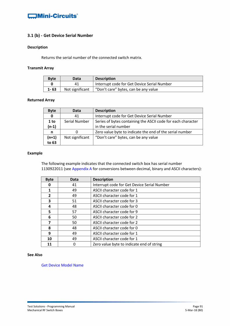
Test Solutions - Programming Manual Page 91 Mechanical RF Switch Boxes 5-Mar-18 (B0)
3.1 (b) - Get Device Serial Number
Description
Returns the serial number of the connected switch matrix. Transmit Array
Byte Data Description
0 41 Interrupt code for Get Device Serial Number
1- 63 Not significant “Don’t care” bytes, can be any value
Returned Array
Byte Data Description
0 41 Interrupt code for Get Device Serial Number
1 to (n-1)
Serial Number Series of bytes containing the ASCII code for each character in the serial number
n 0 Zero value byte to indicate the end of the serial number
(n+1) to 63
Not significant “Don’t care” bytes, can be any value
Example
The following example indicates that the connected switch box has serial number 1130922011 (see Appendix A for conversions between decimal, binary and ASCII characters):
Byte Data Description
0 41 Interrupt code for Get Device Serial Number
1 49 ASCII character code for 1
2 49 ASCII character code for 1
3 51 ASCII character code for 3
4 48 ASCII character code for 0
5 57 ASCII character code for 9
6 50 ASCII character code for 2
7 50 ASCII character code for 2
8 48 ASCII character code for 0
9 49 ASCII character code for 1
10 49 ASCII character code for 1
11 0 Zero value byte to indicate end of string
See Also Get Device Model Name
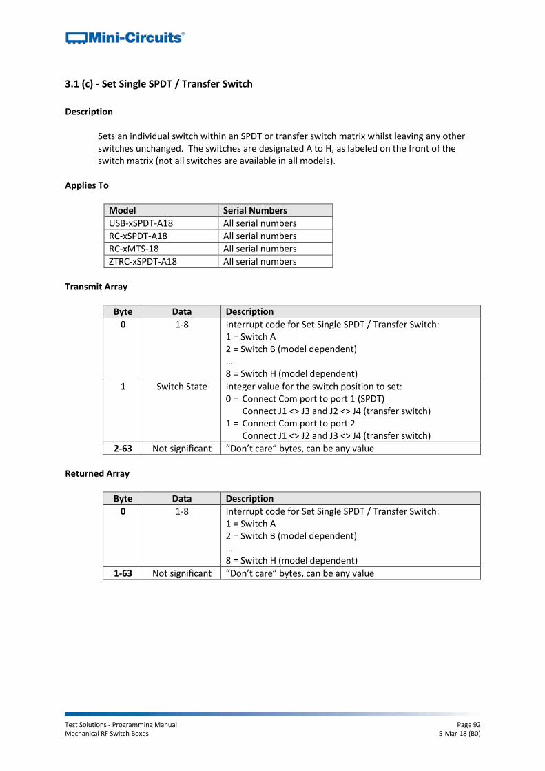
Test Solutions - Programming Manual Page 92 Mechanical RF Switch Boxes 5-Mar-18 (B0)
3.1 (c) - Set Single SPDT / Transfer Switch
Description
Sets an individual switch within an SPDT or transfer switch matrix whilst leaving any other switches unchanged. The switches are designated A to H, as labeled on the front of the switch matrix (not all switches are available in all models).
Applies To
Model Serial Numbers
USB-xSPDT-A18 All serial numbers
RC-xSPDT-A18 All serial numbers
RC-xMTS-18 All serial numbers
ZTRC-xSPDT-A18 All serial numbers
Transmit Array
Byte Data Description
0 1-8 Interrupt code for Set Single SPDT / Transfer Switch: 1 = Switch A 2 = Switch B (model dependent) … 8 = Switch H (model dependent)
1 Switch State Integer value for the switch position to set: 0 = Connect Com port to port 1 (SPDT)
Connect J1 <> J3 and J2 <> J4 (transfer switch) 1 = Connect Com port to port 2
Connect J1 <> J2 and J3 <> J4 (transfer switch)
2-63 Not significant “Don’t care” bytes, can be any value
Returned Array
Byte Data Description
0 1-8 Interrupt code for Set Single SPDT / Transfer Switch: 1 = Switch A 2 = Switch B (model dependent) … 8 = Switch H (model dependent)
1-63 Not significant “Don’t care” bytes, can be any value

Test Solutions - Programming Manual Page 93 Mechanical RF Switch Boxes 5-Mar-18 (B0)
Example
The following transmit array will set switch C to position 1 (Com connected to port 2):
Byte Data Description
0 3 Set Switch C
1 1 Set switch to state 1 (Com port connected to port 2)
The following transmit array will set switch C to position 0 (Com connected to port 1):
Byte Data Description
0 3 Set Switch C
1 0 Set switch to state 0 (Com port connected to port 1)
See Also
Set All SPDT / Transfer Switches Get All SPDT / Transfer Switch States Set All SP4T Switches Set SP6T Switch Get All SP4T Switch States Get SP6T Switch State

Test Solutions - Programming Manual Page 94 Mechanical RF Switch Boxes 5-Mar-18 (B0)
3.1 (d) - Set All SPDT / Transfer Switches
Description
Sets the states of all switches simultaneously within an SPDT or transfer switch box.
Applies To
Model Serial Numbers
USB-xSPDT-A18 All serial numbers
RC-xSPDT-A18 All serial numbers
RC-xMTS-18 All serial numbers
ZTRC-xSPDT-A18 All serial numbers
Transmit Array
Byte Data Description
0 9 Interrupt code for Set All SPDT / Transfer Switches
1 Switch State Numeric value indicating the required switch states. Each bit in BYTE1 represents the state of an individual SPDT or transfer switch with value: 0 = Connect Com port to port 1 (SPDT)
Connect J1 <> J3 and J2 <> J4 (transfer switch) 1 = Connect Com port to port 2
Connect J1 <> J2 and J3 <> J4 (transfer switch) The least significant bit (LSB) represents switch A and the most significant bit (MSB) represents switch H (if applicable).
2-63 Not significant “Don’t care” bytes, can be any value
Returned Array
Byte Data Description
0 9 Interrupt code for Set All SPDT / Transfer Switches
1-63 Not significant “Don’t care” bytes, could be any value

Test Solutions - Programming Manual Page 95 Mechanical RF Switch Boxes 5-Mar-18 (B0)
Example 1 (USB-8SPDT-A18 and RC-8SPDT-A18)
USB-8SPDT-A18 and RC-8SPDT-A18 each have 8 SPDT switches available (named A to H). To set switches A, B and H to state 1 (Com connected to port 2) and all other switches to state 0 (Com port connected to port 1), BYTE1 would be represented as:
Bit Bit 7
(MSB) Bit 6 Bit 5 Bit 4 Bit 3 Bit 2 Bit 1
Bit 0 (LSB)
Switch H G F E D C B A
Description State State State State State State State State
Value 1 0 0 0 0 0 1 1
BYTE1 = 10000011 = decimal 131 The complete transmit array (excluding “don’t care” bytes) would be:
Byte Data Description
0 9 Interrupt code for Set All SPDT / Transfer Switches
1 131 Switch state to set
Example 2 (RC-2MTS-18)
RC-2MTS-18 has 2 transfer switches available (named A and B). To set both switches to state 1 (J1 <> J2 and J3 <> J4), BYTE1 would be represented as:
Bit Bit 7
(MSB) Bit 6 Bit 5 Bit 4 Bit 3 Bit 2 Bit 1
Bit 0 (LSB)
Switch --- --- --- --- --- --- B A
Description Don’t
care
Don’t
care
Don’t
care
Don’t
care
Don’t
care
Don’t
care State State
Value 0 0 0 0 0 0 1 1
BYTE1 = 00000011 = decimal 3 The complete transmit array (excluding “don’t care” bytes) would be:
Byte Data Description
0 9 Interrupt code for Set All SPDT / Transfer Switches
1 3 Switch state to set
See Also
Set Single SPDT / Transfer Switch Get All SPDT / Transfer Switch States Set All SP4T Switches Set SP6T Switch Get All SP4T Switch States Get SP6T Switch State

Test Solutions - Programming Manual Page 96 Mechanical RF Switch Boxes 5-Mar-18 (B0)
3.1 (e) - Set All SP4T Switches
Description
Sets the state of all switches simultaneously within an SP4T switch box. The common port (Com) of each switch can be connected to any one of the input/output ports (ports 1 to 4) or disconnected from all ports.
Applies To
Model Serial Numbers
USB-1SP4T-A18 All serial numbers
RC-xSP4T-x All serial numbers
Transmit Array
Byte Data Value Description
0 Code 9 Interrupt code for Set All SP4T Switches
1 Switch State Numeric value indicating the required switch state. Each bit in BYTE1 corresponds to an input/output port, with the 4 least significant bits (LSB) corresponding to switch A (all models) and the 4 most significant bits (MSB) corresponding to switch B (USB-2SP4T-A18/RC-2SP4T-A18 only). Setting any of these bits to 1 designates that this port should be connected to the Com port. Setting all bits to 0 disconnects all ports. Switch A (all models): If Bits 0 to 3 = 0, disconnect all ports for switch A If Bit 0 = 1, connect switch A Com to port 1 If Bit 1 = 1, connect switch A Com to port 2 If Bit 2 = 1, connect switch A Com to port 3 If Bit 3 = 1, connect switch A Com to port 4 Switch B (USB-2SP4T-A18/RC-2SP4T-A18 only): If Bits 4 to 7 = 0, disconnect all ports for switch B If Bit 4 = 1, connect switch B Com to port 1 If Bit 5 = 1, connect switch B Com to port 2 If Bit 6 = 1, connect switch B Com to port 3 If Bit 7 = 1, connect switch B Com to port 4
2-63 Not significant “Don’t care” bytes, can be any value
Returned Array
Byte Data Description
0 9 Interrupt code for Set All SP4T Switches
1 Status 1 = Command executed successfully 4 = Switch not set (invalid switch state requested)
2-63 Not significant “Don’t care” bytes, could be any value

Test Solutions - Programming Manual Page 97 Mechanical RF Switch Boxes 5-Mar-18 (B0)
Example 1.a (USB-1SP4T-A8/RC-1SP4T-A18)
Bits 4 to 7 refer to switch B which is not applicable for these models, they can therefore take any value. To set switch A to position 3 (connecting Com port to port 3); BYTE1 could be represented as:
Bit Bit 7
(MSB) Bit 6 Bit 5 Bit 4 Bit 3 Bit 2 Bit 1
Bit 0 (LSB)
Switch --- Switch A
Description Don’t
care
Don’t
care
Don’t
care
Don’t
care Port 4 Port 3 Port 2 Port 1
Value 0 0 0 0 0 1 0 0
BYTE1 = 00000100 = decimal 4 The complete transmit array would be:
Byte Data Description
0 9 Interrupt code for Set All SP4T Switches
1 4 Set switch A to position 3
Example 1.b (USB-1SP4T-A8/RC-1SP4T-A18)
To disconnect all ports, bits 0 to 3 must all be 0 (bits 4 to 7 are still “don’t care”):
Bit Bit 7
(MSB) Bit 6 Bit 5 Bit 4 Bit 3 Bit 2 Bit 1
Bit 0 (LSB)
Switch --- Switch A
Description Don’t
care
Don’t
care
Don’t
care
Don’t
care Port 4 Port 3 Port 2 Port 1
Value 0 0 0 0 0 0 0 0
BYTE1 = 00000000 = decimal 0 The complete transmit array would be:
Byte Data Description
0 9 Interrupt code for Set All SP4T Switches
1 0 Disconnect all ports
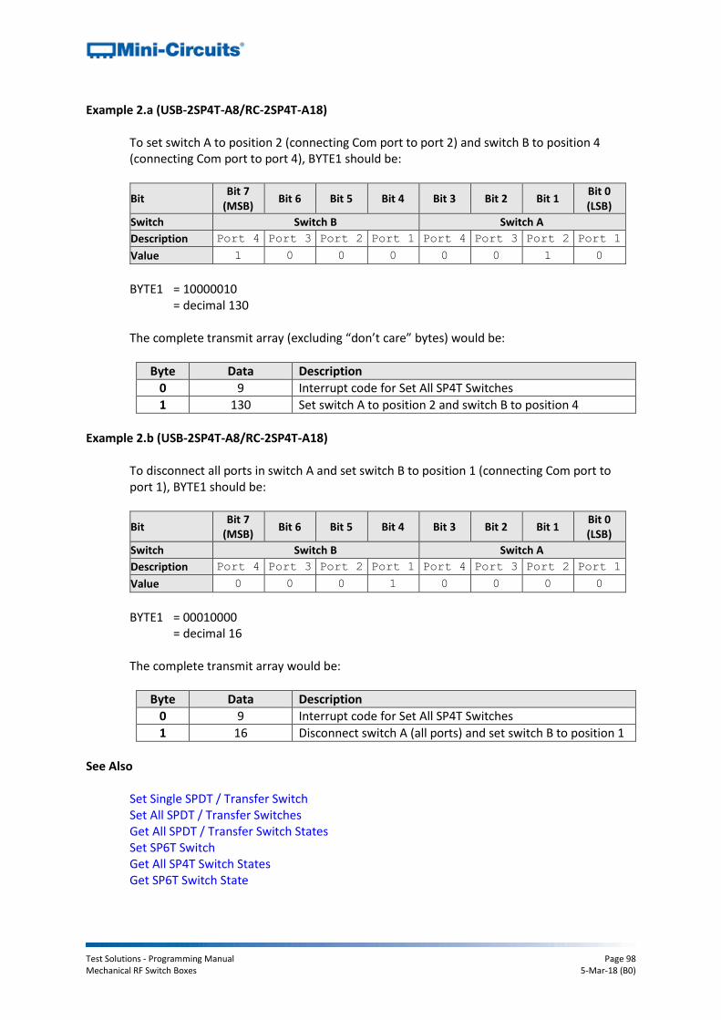
Test Solutions - Programming Manual Page 98 Mechanical RF Switch Boxes 5-Mar-18 (B0)
Example 2.a (USB-2SP4T-A8/RC-2SP4T-A18) To set switch A to position 2 (connecting Com port to port 2) and switch B to position 4 (connecting Com port to port 4), BYTE1 should be:
Bit Bit 7
(MSB) Bit 6 Bit 5 Bit 4 Bit 3 Bit 2 Bit 1
Bit 0 (LSB)
Switch Switch B Switch A
Description Port 4 Port 3 Port 2 Port 1 Port 4 Port 3 Port 2 Port 1
Value 1 0 0 0 0 0 1 0
BYTE1 = 10000010 = decimal 130 The complete transmit array (excluding “don’t care” bytes) would be:
Byte Data Description
0 9 Interrupt code for Set All SP4T Switches
1 130 Set switch A to position 2 and switch B to position 4
Example 2.b (USB-2SP4T-A8/RC-2SP4T-A18)
To disconnect all ports in switch A and set switch B to position 1 (connecting Com port to port 1), BYTE1 should be:
Bit Bit 7
(MSB) Bit 6 Bit 5 Bit 4 Bit 3 Bit 2 Bit 1
Bit 0 (LSB)
Switch Switch B Switch A
Description Port 4 Port 3 Port 2 Port 1 Port 4 Port 3 Port 2 Port 1
Value 0 0 0 1 0 0 0 0
BYTE1 = 00010000 = decimal 16 The complete transmit array would be:
Byte Data Description
0 9 Interrupt code for Set All SP4T Switches
1 16 Disconnect switch A (all ports) and set switch B to position 1
See Also
Set Single SPDT / Transfer Switch Set All SPDT / Transfer Switches Get All SPDT / Transfer Switch States Set SP6T Switch Get All SP4T Switch States Get SP6T Switch State
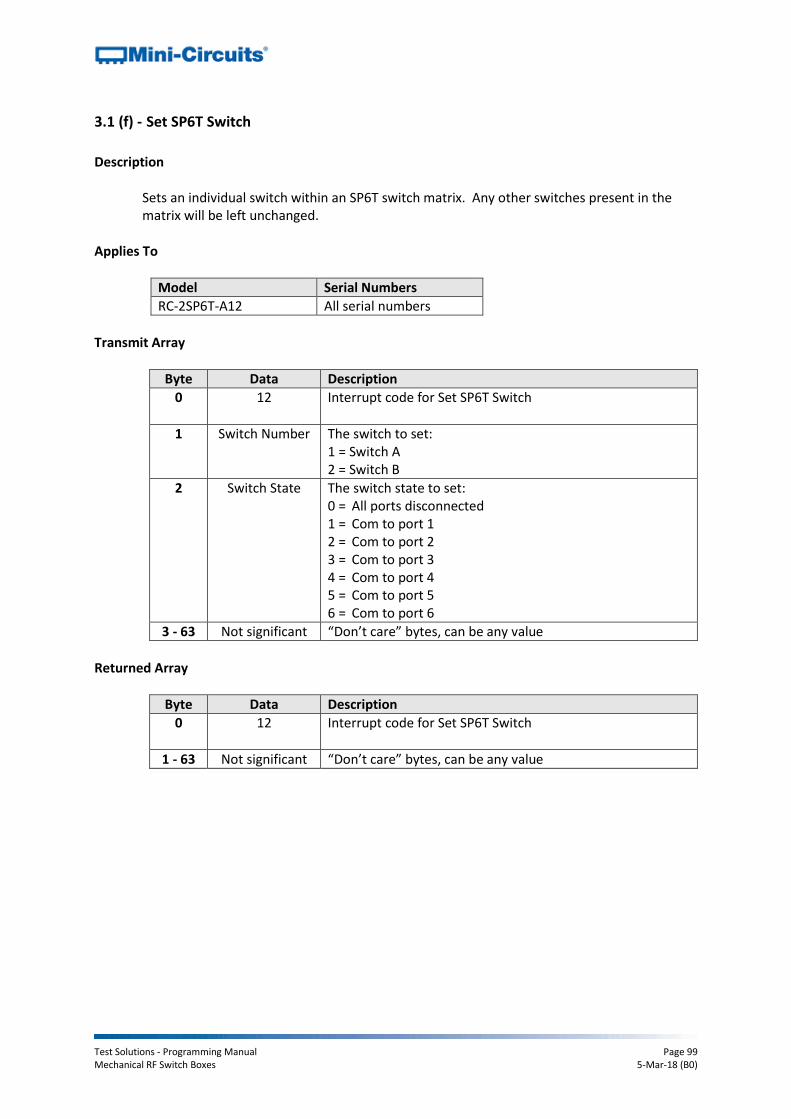
Test Solutions - Programming Manual Page 99 Mechanical RF Switch Boxes 5-Mar-18 (B0)
3.1 (f) - Set SP6T Switch
Description
Sets an individual switch within an SP6T switch matrix. Any other switches present in the matrix will be left unchanged.
Applies To
Model Serial Numbers
RC-2SP6T-A12 All serial numbers
Transmit Array
Byte Data Description
0 12 Interrupt code for Set SP6T Switch
1 Switch Number The switch to set: 1 = Switch A 2 = Switch B
2 Switch State The switch state to set: 0 = All ports disconnected 1 = Com to port 1 2 = Com to port 2 3 = Com to port 3 4 = Com to port 4 5 = Com to port 5 6 = Com to port 6
3 - 63 Not significant “Don’t care” bytes, can be any value
Returned Array
Byte Data Description
0 12 Interrupt code for Set SP6T Switch
1 - 63 Not significant “Don’t care” bytes, can be any value

Test Solutions - Programming Manual Page 100 Mechanical RF Switch Boxes 5-Mar-18 (B0)
Example
The following transmit array will set switch A to position 5 (Com connected to port 5):
Byte Data Description
0 12 Set SP6T Switch
1 1 Set switch A
2 5 Set switch to state 5 (Com port connected to port 5)
The following transmit array will disconnect all ports in switch B:
Byte Data Description
0 12 Set SP6T Switch
1 2 Set switch B
2 0 Disconnect all ports
See Also
Set Single SPDT / Transfer Switch Set All SPDT / Transfer Switches Get All SPDT / Transfer Switch States Set All SP4T Switches Get All SP4T Switch States Get SP6T Switch State
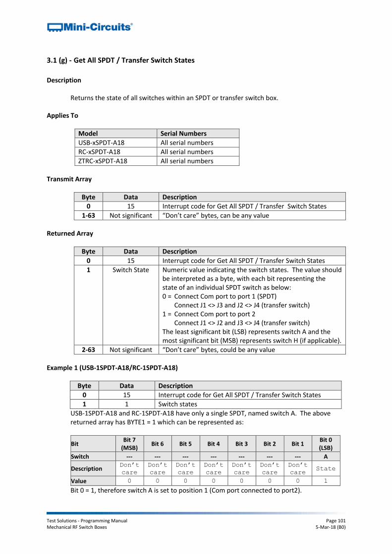
Test Solutions - Programming Manual Page 101 Mechanical RF Switch Boxes 5-Mar-18 (B0)
3.1 (g) - Get All SPDT / Transfer Switch States
Description
Returns the state of all switches within an SPDT or transfer switch box.
Applies To
Model Serial Numbers
USB-xSPDT-A18 All serial numbers
RC-xSPDT-A18 All serial numbers
ZTRC-xSPDT-A18 All serial numbers
Transmit Array
Byte Data Description
0 15 Interrupt code for Get All SPDT / Transfer Switch States
1-63 Not significant “Don’t care” bytes, can be any value
Returned Array
Byte Data Description
0 15 Interrupt code for Get All SPDT / Transfer Switch States
1 Switch State Numeric value indicating the switch states. The value should be interpreted as a byte, with each bit representing the state of an individual SPDT switch as below: 0 = Connect Com port to port 1 (SPDT)
Connect J1 <> J3 and J2 <> J4 (transfer switch) 1 = Connect Com port to port 2
Connect J1 <> J2 and J3 <> J4 (transfer switch) The least significant bit (LSB) represents switch A and the most significant bit (MSB) represents switch H (if applicable).
2-63 Not significant “Don’t care” bytes, could be any value
Example 1 (USB-1SPDT-A18/RC-1SPDT-A18)
Byte Data Description
0 15 Interrupt code for Get All SPDT / Transfer Switch States
1 1 Switch states
USB-1SPDT-A18 and RC-1SPDT-A18 have only a single SPDT, named switch A. The above returned array has BYTE1 = 1 which can be represented as:
Bit Bit 7
(MSB) Bit 6 Bit 5 Bit 4 Bit 3 Bit 2 Bit 1
Bit 0 (LSB)
Switch --- --- --- --- --- --- --- A
Description Don’t
care
Don’t
care
Don’t
care Don’t
care Don’t
care Don’t
care Don’t
care State
Value 0 0 0 0 0 0 0 1
Bit 0 = 1, therefore switch A is set to position 1 (Com port connected to port2).
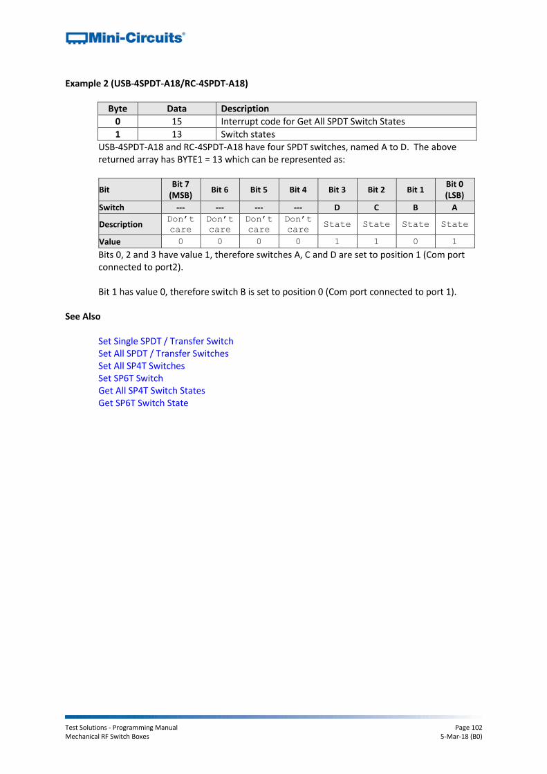
Test Solutions - Programming Manual Page 102 Mechanical RF Switch Boxes 5-Mar-18 (B0)
Example 2 (USB-4SPDT-A18/RC-4SPDT-A18)
Byte Data Description
0 15 Interrupt code for Get All SPDT Switch States
1 13 Switch states
USB-4SPDT-A18 and RC-4SPDT-A18 have four SPDT switches, named A to D. The above returned array has BYTE1 = 13 which can be represented as:
Bit Bit 7
(MSB) Bit 6 Bit 5 Bit 4 Bit 3 Bit 2 Bit 1
Bit 0 (LSB)
Switch --- --- --- --- D C B A
Description Don’t
care
Don’t
care
Don’t
care Don’t
care State State State State
Value 0 0 0 0 1 1 0 1
Bits 0, 2 and 3 have value 1, therefore switches A, C and D are set to position 1 (Com port connected to port2). Bit 1 has value 0, therefore switch B is set to position 0 (Com port connected to port 1).
See Also
Set Single SPDT / Transfer Switch Set All SPDT / Transfer Switches Set All SP4T Switches Set SP6T Switch Get All SP4T Switch States Get SP6T Switch State
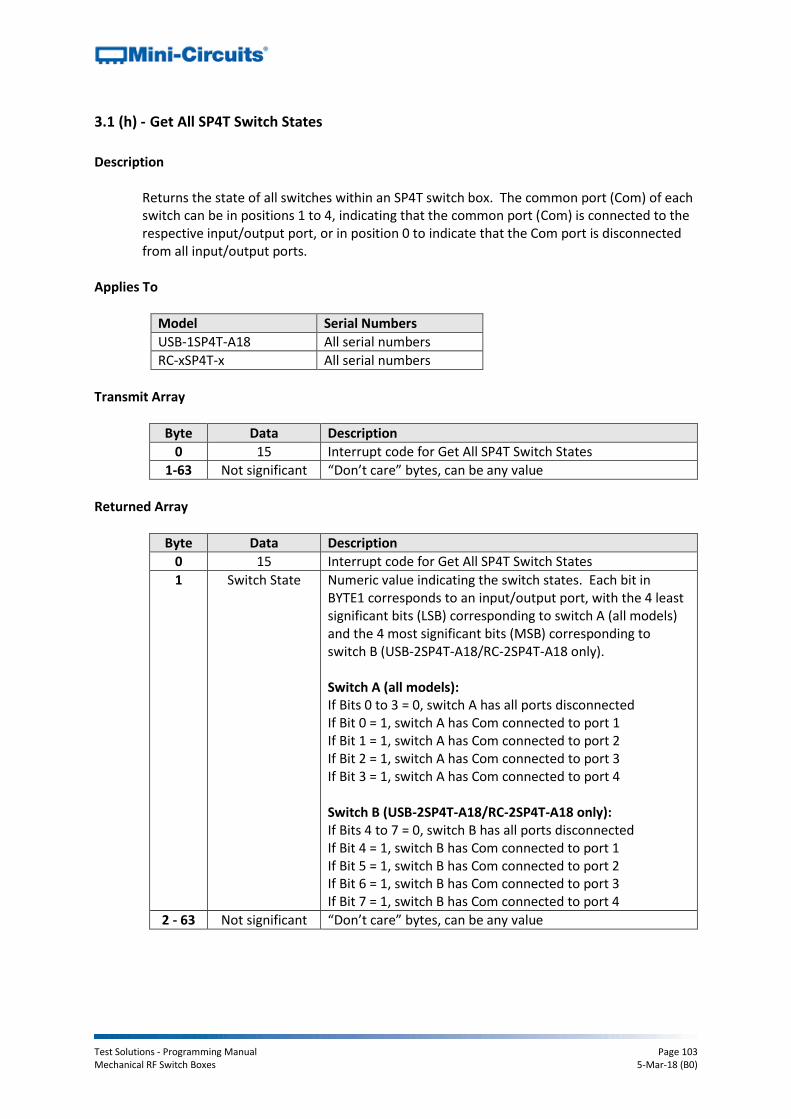
Test Solutions - Programming Manual Page 103 Mechanical RF Switch Boxes 5-Mar-18 (B0)
3.1 (h) - Get All SP4T Switch States
Description
Returns the state of all switches within an SP4T switch box. The common port (Com) of each switch can be in positions 1 to 4, indicating that the common port (Com) is connected to the respective input/output port, or in position 0 to indicate that the Com port is disconnected from all input/output ports.
Applies To
Model Serial Numbers
USB-1SP4T-A18 All serial numbers
RC-xSP4T-x All serial numbers
Transmit Array
Byte Data Description
0 15 Interrupt code for Get All SP4T Switch States
1-63 Not significant “Don’t care” bytes, can be any value
Returned Array
Byte Data Description
0 15 Interrupt code for Get All SP4T Switch States
1 Switch State Numeric value indicating the switch states. Each bit in BYTE1 corresponds to an input/output port, with the 4 least significant bits (LSB) corresponding to switch A (all models) and the 4 most significant bits (MSB) corresponding to switch B (USB-2SP4T-A18/RC-2SP4T-A18 only). Switch A (all models): If Bits 0 to 3 = 0, switch A has all ports disconnected If Bit 0 = 1, switch A has Com connected to port 1 If Bit 1 = 1, switch A has Com connected to port 2 If Bit 2 = 1, switch A has Com connected to port 3 If Bit 3 = 1, switch A has Com connected to port 4 Switch B (USB-2SP4T-A18/RC-2SP4T-A18 only): If Bits 4 to 7 = 0, switch B has all ports disconnected If Bit 4 = 1, switch B has Com connected to port 1 If Bit 5 = 1, switch B has Com connected to port 2 If Bit 6 = 1, switch B has Com connected to port 3 If Bit 7 = 1, switch B has Com connected to port 4
2 - 63 Not significant “Don’t care” bytes, can be any value
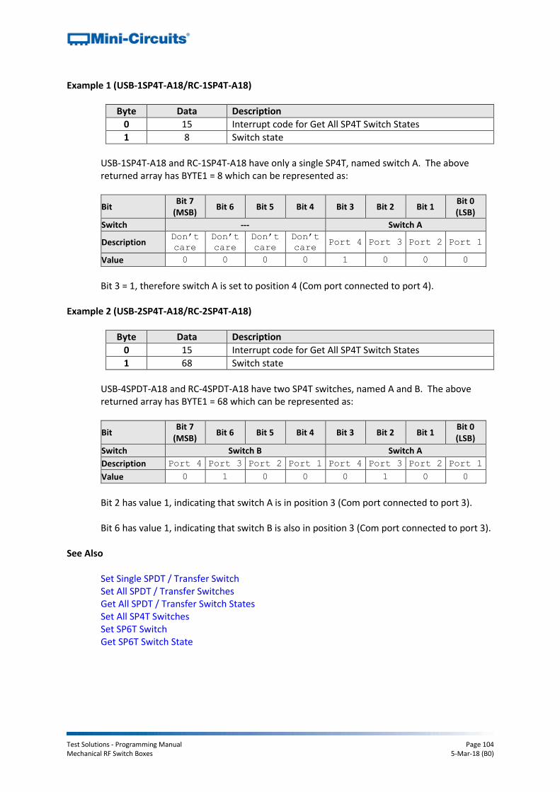
Test Solutions - Programming Manual Page 104 Mechanical RF Switch Boxes 5-Mar-18 (B0)
Example 1 (USB-1SP4T-A18/RC-1SP4T-A18)
Byte Data Description
0 15 Interrupt code for Get All SP4T Switch States
1 8 Switch state
USB-1SP4T-A18 and RC-1SP4T-A18 have only a single SP4T, named switch A. The above returned array has BYTE1 = 8 which can be represented as:
Bit Bit 7
(MSB) Bit 6 Bit 5 Bit 4 Bit 3 Bit 2 Bit 1
Bit 0 (LSB)
Switch --- Switch A
Description Don’t
care
Don’t
care
Don’t
care Don’t
care Port 4 Port 3 Port 2 Port 1
Value 0 0 0 0 1 0 0 0
Bit 3 = 1, therefore switch A is set to position 4 (Com port connected to port 4).
Example 2 (USB-2SP4T-A18/RC-2SP4T-A18)
Byte Data Description
0 15 Interrupt code for Get All SP4T Switch States
1 68 Switch state
USB-4SPDT-A18 and RC-4SPDT-A18 have two SP4T switches, named A and B. The above returned array has BYTE1 = 68 which can be represented as:
Bit Bit 7
(MSB) Bit 6 Bit 5 Bit 4 Bit 3 Bit 2 Bit 1
Bit 0 (LSB)
Switch Switch B Switch A
Description Port 4 Port 3 Port 2 Port 1 Port 4 Port 3 Port 2 Port 1
Value 0 1 0 0 0 1 0 0
Bit 2 has value 1, indicating that switch A is in position 3 (Com port connected to port 3). Bit 6 has value 1, indicating that switch B is also in position 3 (Com port connected to port 3).
See Also
Set Single SPDT / Transfer Switch Set All SPDT / Transfer Switches Get All SPDT / Transfer Switch States Set All SP4T Switches Set SP6T Switch Get SP6T Switch State
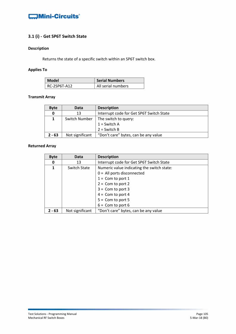
Test Solutions - Programming Manual Page 105 Mechanical RF Switch Boxes 5-Mar-18 (B0)
3.1 (i) - Get SP6T Switch State
Description
Returns the state of a specific switch within an SP6T switch box.
Applies To
Model Serial Numbers
RC-2SP6T-A12 All serial numbers
Transmit Array
Byte Data Description
0 13 Interrupt code for Get SP6T Switch State
1 Switch Number The switch to query: 1 = Switch A 2 = Switch B
2 - 63 Not significant “Don’t care” bytes, can be any value
Returned Array
Byte Data Description
0 13 Interrupt code for Get SP6T Switch State
1 Switch State Numeric value indicating the switch state: 0 = All ports disconnected 1 = Com to port 1 2 = Com to port 2 3 = Com to port 3 4 = Com to port 4 5 = Com to port 5 6 = Com to port 6
2 - 63 Not significant “Don’t care” bytes, can be any value
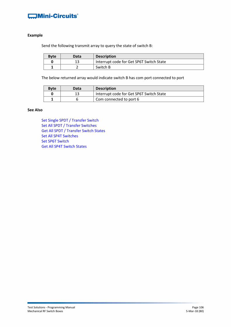
Test Solutions - Programming Manual Page 106 Mechanical RF Switch Boxes 5-Mar-18 (B0)
Example Send the following transmit array to query the state of switch B:
Byte Data Description
0 13 Interrupt code for Get SP6T Switch State
1 2 Switch B
The below returned array would indicate switch B has com port connected to port
Byte Data Description
0 13 Interrupt code for Get SP6T Switch State
1 6 Com connected to port 6
See Also
Set Single SPDT / Transfer Switch Set All SPDT / Transfer Switches Get All SPDT / Transfer Switch States Set All SP4T Switches Set SP6T Switch Get All SP4T Switch States

Test Solutions - Programming Manual Page 107 Mechanical RF Switch Boxes 5-Mar-18 (B0)
3.1 (j) - Set Power-Up Mode
Description
Sets the switch state to be loaded when DC power is first applied to the switch box, either the last remembered state or the default state. To ensure proper operation of the "last remembered state" option, the Save Switch Counters & States command should be sent prior to powering off the switch box.
Applies To
Model Firmware
All models D2 or later
Transmit Array
Byte Data Description
0 89 Interrupt code for Set Power-Up Mode
1 Mode The power-up mode: 0 = All switches will power-up in the last remembered state 1 = All switches will power-up in the default state:
SP4T & SP6T: All ports disconnected SPDT: Com connected to port 1 Transfer: J1 <> J3 and J2 <> J4
2 - 63 Not significant “Don’t care” bytes, can be any value
Returned Array
Byte Data Description
0 89 Interrupt code for Set Power-Up Mode
1 - 63 Not significant “Don’t care” bytes, can be any value
Example
The following transmit array will set the switches to power-up in the last remembered state:
Byte Data Description
0 89 Set Power-Up Mode
1 1 Power-up in the last remembered state
See Also
Get Power-Up Mode Save Switch Counters & States
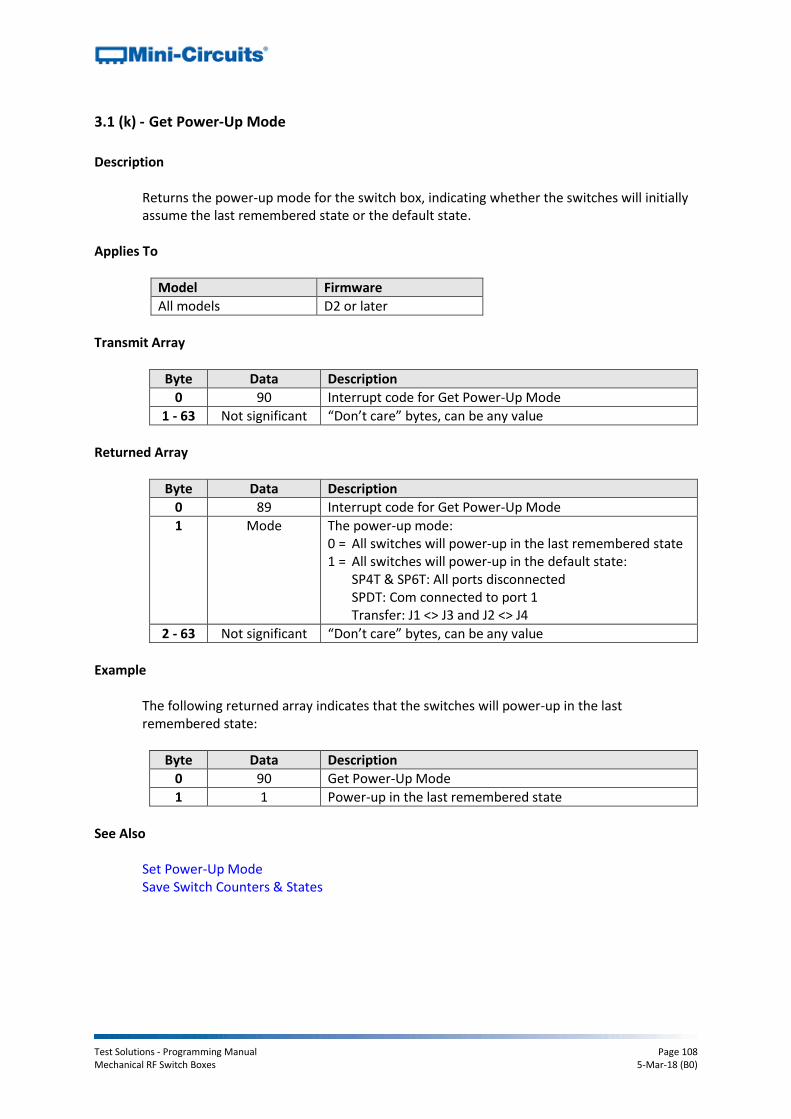
Test Solutions - Programming Manual Page 108 Mechanical RF Switch Boxes 5-Mar-18 (B0)
3.1 (k) - Get Power-Up Mode
Description
Returns the power-up mode for the switch box, indicating whether the switches will initially assume the last remembered state or the default state.
Applies To
Model Firmware
All models D2 or later
Transmit Array
Byte Data Description
0 90 Interrupt code for Get Power-Up Mode
1 - 63 Not significant “Don’t care” bytes, can be any value
Returned Array
Byte Data Description
0 89 Interrupt code for Get Power-Up Mode
1 Mode The power-up mode: 0 = All switches will power-up in the last remembered state 1 = All switches will power-up in the default state:
SP4T & SP6T: All ports disconnected SPDT: Com connected to port 1 Transfer: J1 <> J3 and J2 <> J4
2 - 63 Not significant “Don’t care” bytes, can be any value
Example
The following returned array indicates that the switches will power-up in the last remembered state:
Byte Data Description
0 90 Get Power-Up Mode
1 1 Power-up in the last remembered state
See Also
Set Power-Up Mode Save Switch Counters & States

Test Solutions - Programming Manual Page 109 Mechanical RF Switch Boxes 5-Mar-18 (B0)
3.1 (l) - Get Firmware
Description
Returns the internal firmware version of the switch box. Transmit Array
Byte Data Description
0 99 Interrupt code for Get Firmware
1- 63 Not significant “Don’t care” bytes, can be any value
Returned Array
Byte Data Description
0 99 Interrupt code for Get Firmware
1 Reserved Internal code for factory use only
2 Reserved Internal code for factory use only
3 Reserved Internal code for factory use only
4 Reserved Internal code for factory use only
5 Firmware Letter
ASCII code for the first character in the firmware revision identifier
6 Firmware Number
ASCII code for the second character in the firmware revision identifier
7-63 Not significant “Don’t care” bytes, could be any value
Example
The following returned array indicates that the switch box has firmware version C3:
Byte Data Description
0 99 Interrupt code for Get Firmware
1 55 Internal code for factory use only
2 52 Internal code for factory use only
3 83 Internal code for factory use only
4 87 Internal code for factory use only
5 67 ASCII code for the letter “C”
6 51 ASCII code for the number 3
7-63 Not significant “Don’t care” bytes, could be any value

Test Solutions - Programming Manual Page 110 Mechanical RF Switch Boxes 5-Mar-18 (B0)
3.1 (m) - Get Internal Temperature
Description
Returns the internal temperature measured at 1 of the internal sensors (model dependent):
USB-1SPDT-A18 / RC-1SPDT-A18 (1 sensor)
USB-1SP4T-A18 / RC-1SP4T-A18 (1 sensor)
RC-2MTS-18 (2 sensors)
USB-2SPDT-A18 / RC-2SPDT-A18 (2 sensors)
USB-3SPDT-A18 / RC-3SPDT-A18 (2 sensors)
USB-4SPDT-A18 / RC-4SPDT-A18 (2 sensors)
USB-8SPDT-A18 / RC-8SPDT-A18 (3 sensors)
RC-2SP4T-x (2 sensors)
RC-2SP6T-A12 (2 sensors) Note: Units with serial numbers earlier than 11108010000 may have a different number of sensors than indicated above. If a sensor that does not exist is polled (for example there is no sensor 2 on USB-1SPDT-A18) the temperature returned will be “+25.00”.
Transmit Array
Byte Data Description
0 114, 115 or 118 Interrupt code for Get Internal Temperature: 114 = Check temperature sensor 1 115 = Check temperature sensor 2 (if available) 118 = Check temperature sensor 3 (if available)
1-63 Not significant “Don’t care” bytes, can be any value
Returned Array
Byte Data Description
0 114, 115 or 118 Interrupt code for Get Internal Temperature: 114 = Check temperature sensor 1 115 = Check temperature sensor 2 (if available) 118 = Check temperature sensor 3 (if available)
1 43 or 45 ASCII code for the first character of the temperature: 43 = positive (+) 45 = negative (-)
2 Temperature Digit 1
ASCII character code for the first digit of the temperature reading
3 Temperature Digit 2
ASCII character code for the second digit of the temperature reading
4 46 ASCII character code for the decimal point symbol (“.”)
5 Temperature Decimal Place 1
ASCII character code for the first decimal place of the temperature reading
6 Temperature Decimal Place 2
ASCII character code for the second decimal place of the temperature reading
7-63 Not significant “Don’t care” bytes, can be any value
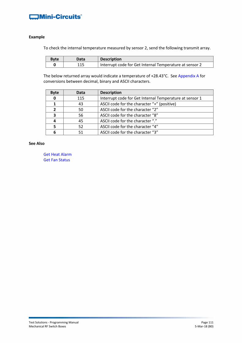
Test Solutions - Programming Manual Page 111 Mechanical RF Switch Boxes 5-Mar-18 (B0)
Example
To check the internal temperature measured by sensor 2, send the following transmit array.
Byte Data Description
0 115 Interrupt code for Get Internal Temperature at sensor 2
The below returned array would indicate a temperature of +28.43°C. See Appendix A for conversions between decimal, binary and ASCII characters.
Byte Data Description
0 115 Interrupt code for Get Internal Temperature at sensor 1
1 43 ASCII code for the character “+” (positive)
2 50 ASCII code for the character “2”
3 56 ASCII code for the character “8”
4 45 ASCII code for the character “.”
5 52 ASCII code for the character “4”
6 51 ASCII code for the character “3”
See Also Get Heat Alarm Get Fan Status
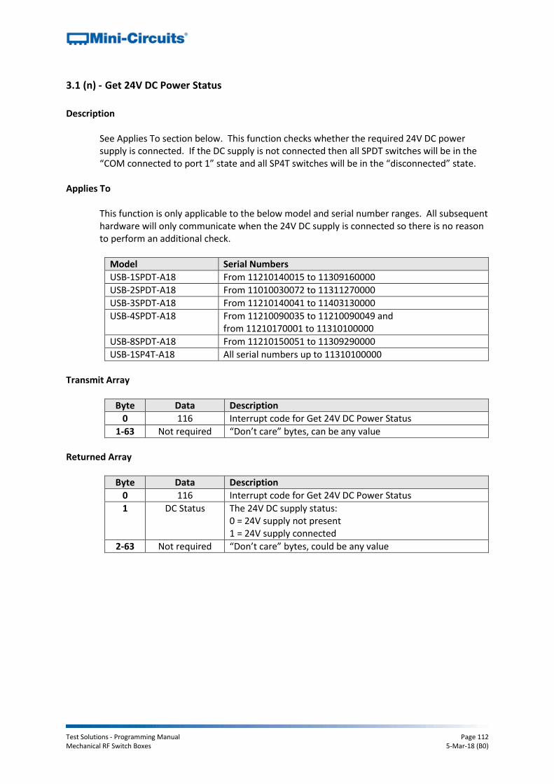
Test Solutions - Programming Manual Page 112 Mechanical RF Switch Boxes 5-Mar-18 (B0)
3.1 (n) - Get 24V DC Power Status
Description
See Applies To section below. This function checks whether the required 24V DC power supply is connected. If the DC supply is not connected then all SPDT switches will be in the “COM connected to port 1” state and all SP4T switches will be in the “disconnected” state.
Applies To This function is only applicable to the below model and serial number ranges. All subsequent hardware will only communicate when the 24V DC supply is connected so there is no reason to perform an additional check.
Model Serial Numbers
USB-1SPDT-A18 From 11210140015 to 11309160000
USB-2SPDT-A18 From 11010030072 to 11311270000
USB-3SPDT-A18 From 11210140041 to 11403130000
USB-4SPDT-A18 From 11210090035 to 11210090049 and from 11210170001 to 11310100000
USB-8SPDT-A18 From 11210150051 to 11309290000
USB-1SP4T-A18 All serial numbers up to 11310100000
Transmit Array
Byte Data Description
0 116 Interrupt code for Get 24V DC Power Status
1-63 Not required “Don’t care” bytes, can be any value
Returned Array
Byte Data Description
0 116 Interrupt code for Get 24V DC Power Status
1 DC Status The 24V DC supply status: 0 = 24V supply not present 1 = 24V supply connected
2-63 Not required “Don’t care” bytes, could be any value

Test Solutions - Programming Manual Page 113 Mechanical RF Switch Boxes 5-Mar-18 (B0)
Example
The following return array would indicate the 24V DC supply is not connected:
Byte Data Description
0 116 Interrupt code for Get 24V DC Power Status
1 0 24V supply not present
The following return array would indicate the 24V DC supply is connected:
Byte Data Description
0 116 Interrupt code for Get 24V DC Power Status
1 1 24V supply connected
See Also Get Heat Alarm Get Fan Status

Test Solutions - Programming Manual Page 114 Mechanical RF Switch Boxes 5-Mar-18 (B0)
3.1 (o) - Get Heat Alarm
Description
Returns an alarm notification if any of the internal temperature sensors exceeds the factory programmed limits (45°C on the PCB or 48°C on the internal switch case).
Transmit Array
Byte Data Description
0 117 Interrupt code for Get Heat Alarm
1-63 Not required “Don’t care” bytes, can be any value
Returned Array
Byte Data Description
0 117 Interrupt code for Get Heat Alarm
1 Alarm Status The heat alarm status: 0 = All temperature sensors are within allowed limits 1 = Temperature exceeds specified limits
2-63 Not required “Don’t care” bytes, could be any value
Example
The following return array would indicate the unit is within normal temperature limits:
Byte Data Description
0 117 Interrupt code for Get Heat Alarm
1 0 All temperature sensors are within allowed limits
The following return array would indicate the unit has exceeded the internal temperature limit:
Byte Data Description
0 117 Interrupt code for Get Heat Alarm
1 1 Temperature exceeds specified limits
See Also Get Internal Temperature Get Fan Status
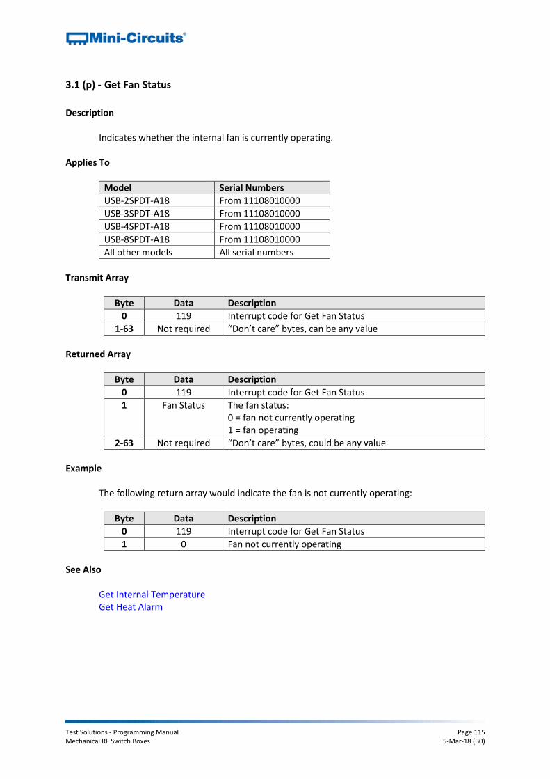
Test Solutions - Programming Manual Page 115 Mechanical RF Switch Boxes 5-Mar-18 (B0)
3.1 (p) - Get Fan Status
Description
Indicates whether the internal fan is currently operating. Applies To
Model Serial Numbers
USB-2SPDT-A18 From 11108010000
USB-3SPDT-A18 From 11108010000
USB-4SPDT-A18 From 11108010000
USB-8SPDT-A18 From 11108010000
All other models All serial numbers
Transmit Array
Byte Data Description
0 119 Interrupt code for Get Fan Status
1-63 Not required “Don’t care” bytes, can be any value
Returned Array
Byte Data Description
0 119 Interrupt code for Get Fan Status
1 Fan Status The fan status: 0 = fan not currently operating 1 = fan operating
2-63 Not required “Don’t care” bytes, could be any value
Example
The following return array would indicate the fan is not currently operating:
Byte Data Description
0 119 Interrupt code for Get Fan Status
1 0 Fan not currently operating
See Also Get Internal Temperature Get Heat Alarm
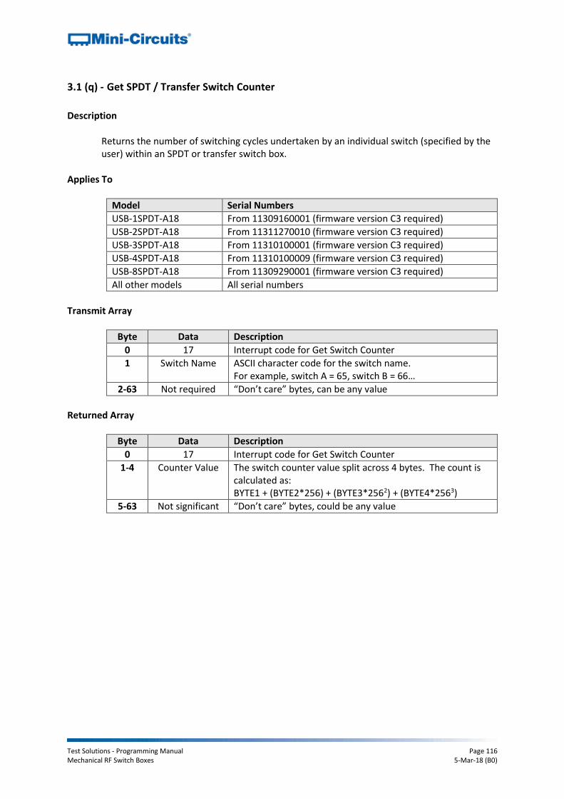
Test Solutions - Programming Manual Page 116 Mechanical RF Switch Boxes 5-Mar-18 (B0)
3.1 (q) - Get SPDT / Transfer Switch Counter
Description
Returns the number of switching cycles undertaken by an individual switch (specified by the user) within an SPDT or transfer switch box.
Applies To
Model Serial Numbers
USB-1SPDT-A18 From 11309160001 (firmware version C3 required)
USB-2SPDT-A18 From 11311270010 (firmware version C3 required)
USB-3SPDT-A18 From 11310100001 (firmware version C3 required)
USB-4SPDT-A18 From 11310100009 (firmware version C3 required)
USB-8SPDT-A18 From 11309290001 (firmware version C3 required)
All other models All serial numbers
Transmit Array
Byte Data Description
0 17 Interrupt code for Get Switch Counter
1 Switch Name ASCII character code for the switch name. For example, switch A = 65, switch B = 66…
2-63 Not required “Don’t care” bytes, can be any value
Returned Array
Byte Data Description
0 17 Interrupt code for Get Switch Counter
1-4 Counter Value The switch counter value split across 4 bytes. The count is calculated as: BYTE1 + (BYTE2*256) + (BYTE3*2562) + (BYTE4*2563)
5-63 Not significant “Don’t care” bytes, could be any value

Test Solutions - Programming Manual Page 117 Mechanical RF Switch Boxes 5-Mar-18 (B0)
Example
To query the counter of switch C, send:
Byte Data Description
0 17 Interrupt code for Get Switch Counter
1 67 Query switch C counter (ASCII character code for C = 67)
Calculate the counter value from the below example return array:
Byte Data Description
0 17 Interrupt code for Get Switch Counter
1 97 The switch counter value split across 4 bytes, calculated as: COUNT = 97 + (132*256) + (11*2562) + (0*2563) = 754,785 cycles
2 132
3 11
4 0
See Also
Get All Switch Counters Save Switch Counters
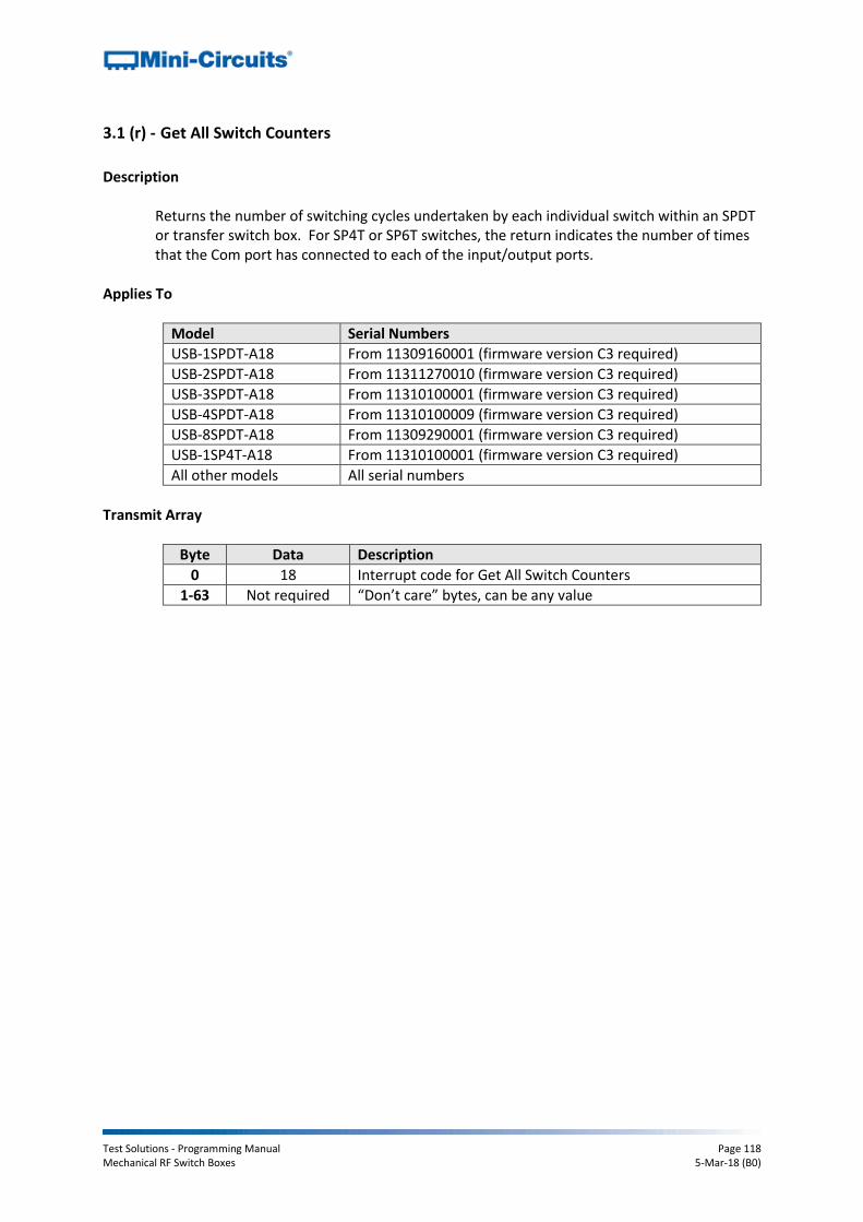
Test Solutions - Programming Manual Page 118 Mechanical RF Switch Boxes 5-Mar-18 (B0)
3.1 (r) - Get All Switch Counters
Description
Returns the number of switching cycles undertaken by each individual switch within an SPDT or transfer switch box. For SP4T or SP6T switches, the return indicates the number of times that the Com port has connected to each of the input/output ports.
Applies To
Model Serial Numbers
USB-1SPDT-A18 From 11309160001 (firmware version C3 required)
USB-2SPDT-A18 From 11311270010 (firmware version C3 required)
USB-3SPDT-A18 From 11310100001 (firmware version C3 required)
USB-4SPDT-A18 From 11310100009 (firmware version C3 required)
USB-8SPDT-A18 From 11309290001 (firmware version C3 required)
USB-1SP4T-A18 From 11310100001 (firmware version C3 required)
All other models All serial numbers
Transmit Array
Byte Data Description
0 18 Interrupt code for Get All Switch Counters
1-63 Not required “Don’t care” bytes, can be any value

Test Solutions - Programming Manual Page 119 Mechanical RF Switch Boxes 5-Mar-18 (B0)
Returned Array (SPDT Switch Boxes)
Byte Data Description
0 18 Interrupt code for Get All Switch Counters
1-4 Switch A Counter Value
Switch A counter value split across 4 bytes. The count is calculated as: BYTE1 + (BYTE2*256) + (BYTE3*2562) + (BYTE4*2563)
5-8 Switch B Counter Value
Switch B (if applicable) counter value split across 4 bytes. The count is calculated as: BYTE5 + (BYTE6*256) + (BYTE7*2562) + (BYTE8*2563)
9-12 Switch C Counter Value
Switch C (if applicable) counter value split across 4 bytes. The count is calculated as: BYTE9 + (BYTE10*256) + (BYTE11*2562) + (BYTE12*2563)
13-16 Switch D Counter Value
Switch D (if applicable) counter value split across 4 bytes. The count is calculated as: BYTE13 + (BYTE14*256) + (BYTE15*2562) + (BYTE16*2563)
17-20 Switch E Counter Value
Switch E (if applicable) counter value split across 4 bytes. The count is calculated as: BYTE17 + (BYTE18*256) + (BYTE19*2562) + (BYTE20*2563)
21-24 Switch F Counter Value
Switch F (if applicable) counter value split across 4 bytes. The count is calculated as: BYTE21 + (BYTE22*256) + (BYTE23*2562) + (BYTE24*2563)
25-28 Switch G Counter Value
Switch G (if applicable) counter value split across 4 bytes. The count is calculated as: BYTE25 + (BYTE26*256) + (BYTE27*2562) + (BYTE28*2563)
29-32 Switch H Counter Value
Switch H (if applicable) counter value split across 4 bytes. The count is calculated as: BYTE29 + (BYTE30*256) + (BYTE31*2562) + (BYTE32*2563)
33-63 Not significant “Don’t care” bytes, could be any value
Note: Bytes relating to switches that are not available in the connected hardware become “don’t care” bytes and will contain arbitrary values. For example, RC-3SPDT-A18 has 3 SPDT switches, named A to C. Therefore, only bytes 0 to 12 are relevant in the returned array.
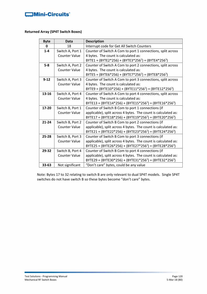
Test Solutions - Programming Manual Page 120 Mechanical RF Switch Boxes 5-Mar-18 (B0)
Returned Array (SP4T Switch Boxes)
Byte Data Description
0 18 Interrupt code for Get All Switch Counters
1-4 Switch A, Port 1 Counter Value
Counter of Switch A Com to port 1 connections, split across 4 bytes. The count is calculated as: BYTE1 + (BYTE2*256) + (BYTE3*2562) + (BYTE4*2563)
5-8 Switch A, Port 2 Counter Value
Counter of Switch A Com to port 2 connections, split across 4 bytes. The count is calculated as: BYTE5 + (BYTE6*256) + (BYTE7*2562) + (BYTE8*2563)
9-12 Switch A, Port 3 Counter Value
Counter of Switch A Com to port 3 connections, split across 4 bytes. The count is calculated as: BYTE9 + (BYTE10*256) + (BYTE11*2562) + (BYTE12*2563)
13-16 Switch A, Port 4 Counter Value
Counter of Switch A Com to port 4 connections, split across 4 bytes. The count is calculated as: BYTE13 + (BYTE14*256) + (BYTE15*2562) + (BYTE16*2563)
17-20 Switch B, Port 1 Counter Value
Counter of Switch B Com to port 1 connections (if applicable), split across 4 bytes. The count is calculated as: BYTE17 + (BYTE18*256) + (BYTE19*2562) + (BYTE20*2563)
21-24 Switch B, Port 2 Counter Value
Counter of Switch B Com to port 2 connections (if applicable), split across 4 bytes. The count is calculated as: BYTE21 + (BYTE22*256) + (BYTE23*2562) + (BYTE24*2563)
25-28 Switch B, Port 3 Counter Value
Counter of Switch B Com to port 3 connections (if applicable), split across 4 bytes. The count is calculated as: BYTE25 + (BYTE26*256) + (BYTE27*2562) + (BYTE28*2563)
29-32 Switch B, Port 4 Counter Value
Counter of Switch B Com to port 4 connections (if applicable), split across 4 bytes. The count is calculated as: BYTE29 + (BYTE30*256) + (BYTE31*2562) + (BYTE32*2563)
33-63 Not significant “Don’t care” bytes, could be any value
Note: Bytes 17 to 32 relating to switch B are only relevant to dual SP4T models. Single SP4T switches do not have switch B so these bytes become “don’t care” bytes.

Test Solutions - Programming Manual Page 121 Mechanical RF Switch Boxes 5-Mar-18 (B0)
Example (SPDT Switch Boxes)
The following returned array shows the counter values for RC-3SPDT-A18 (three SPDT switch box):
Byte Data Description
0 18 Interrupt code for Get All Switch Counters
1 97 Switch A counter value split across 4 bytes, calculated as: COUNT = 97 + (132*256) + (11*2562) + (0 * 2563) = 754,785 cycles
2 132
3 11
4 0
5 5 Switch B counter value split across 4 bytes, calculated as: COUNT = 5 + (15*256) + (5*2562) + (0 * 2563) = 331,525 cycles
6 15
7 5
8 0
9 111 Switch C counter value split across 4 bytes, calculated as: COUNT = 111 + (97*256) + (2*2562) + (1 * 2563) = 16,933,231 cycles
10 97
11 2
12 1
Example (SP4T Switch Boxes)
The following returned array shows the counter values for USB-1SP4T-A18 (single SP4T switch box):
Byte Data Description
0 18 Interrupt code for Get All Switch Counters
1 97 Counter of Switch A Com to port 1 connections, split across 4 bytes, calculated as: COUNT = 97 + (132*256) + (11*2562) + (0 * 2563) = 754,785 cycles
2 132
3 11
4 0
5 5 Counter of Switch A Com to port 1 connections, split across 4 bytes, calculated as: COUNT = 5 + (15*256) + (5*2562) + (0 * 2563) = 331,525 cycles
6 15
7 5
8 0
9 111 Counter of Switch A Com to port 1 connections, split across 4 bytes, calculated as: COUNT = 111 + (97*256) + (2*2562) + (1 * 2563) = 16,933,231 cycles
10 97
11 2
12 1
13 15 Counter of Switch A Com to port 1 connections, split across 4 bytes, calculated as: COUNT = 15 + (20*256) + (3*2562) + (0 * 2563) = 201,743 cycles
14 20
15 3
16 0
See Also
Get SPDT / Transfer Switch Counter Save Switch Counters
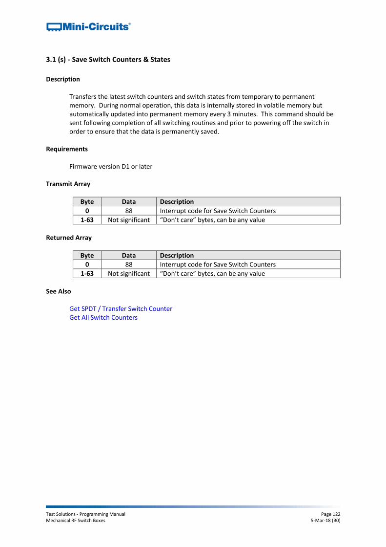
Test Solutions - Programming Manual Page 122 Mechanical RF Switch Boxes 5-Mar-18 (B0)
3.1 (s) - Save Switch Counters & States
Description
Transfers the latest switch counters and switch states from temporary to permanent memory. During normal operation, this data is internally stored in volatile memory but automatically updated into permanent memory every 3 minutes. This command should be sent following completion of all switching routines and prior to powering off the switch in order to ensure that the data is permanently saved.
Requirements
Firmware version D1 or later Transmit Array
Byte Data Description
0 88 Interrupt code for Save Switch Counters
1-63 Not significant “Don’t care” bytes, can be any value
Returned Array
Byte Data Description
0 88 Interrupt code for Save Switch Counters
1-63 Not significant “Don’t care” bytes, can be any value
See Also
Get SPDT / Transfer Switch Counter Get All Switch Counters
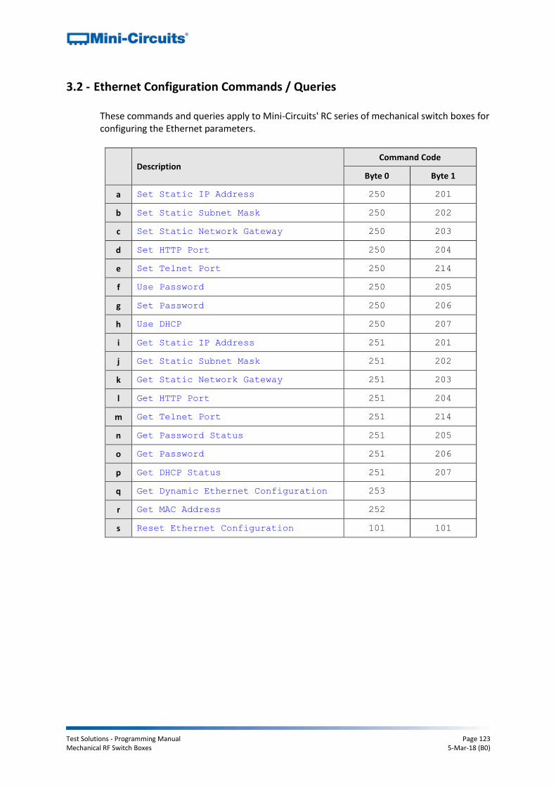
Test Solutions - Programming Manual Page 123 Mechanical RF Switch Boxes 5-Mar-18 (B0)
3.2 - Ethernet Configuration Commands / Queries
These commands and queries apply to Mini-Circuits' RC series of mechanical switch boxes for configuring the Ethernet parameters.
Description Command Code
Byte 0 Byte 1
a Set Static IP Address 250 201
b Set Static Subnet Mask 250 202
c Set Static Network Gateway 250 203
d Set HTTP Port 250 204
e Set Telnet Port 250 214
f Use Password 250 205
g Set Password 250 206
h Use DHCP 250 207
i Get Static IP Address 251 201
j Get Static Subnet Mask 251 202
k Get Static Network Gateway 251 203
l Get HTTP Port 251 204
m Get Telnet Port 251 214
n Get Password Status 251 205
o Get Password 251 206
p Get DHCP Status 251 207
q Get Dynamic Ethernet Configuration 253
r Get MAC Address 252
s Reset Ethernet Configuration 101 101

Test Solutions - Programming Manual Page 124 Mechanical RF Switch Boxes 5-Mar-18 (B0)
3.2 (a) - Set Static IP Address
Description
Sets the static IP address to be used when DHCP (dynamic host control protocol) is disabled. Transmit Array
Byte Data Description
0 250 Interrupt code for Set Ethernet Configuration
1 201 Interrupt code for Set IP Address
2 IP_Byte0 First byte of IP address
3 IP_Byte1 Second byte of IP address
4 IP_Byte2 Third byte of IP address
5 IP_Byte3 Fourth byte of IP address
6 - 63 Not significant Any value
Returned Array
Byte Data Description
0 250 Interrupt code for Set Ethernet Configuration
1 - 63 Not significant Any value
Example
To set the static IP address to 192.168.100.100, the transmit array is:
Byte Data Description
0 250 Interrupt code for Set Ethernet Configuration
1 201 Interrupt code for Set IP Address
2 192 First byte of IP address
3 168 Second byte of IP address
4 100 Third byte of IP address
5 100 Fourth byte of IP address
See Also
Use DHCP Get Static IP Address Reset Ethernet Configuration
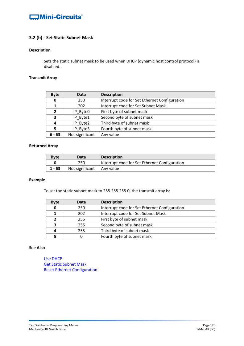
Test Solutions - Programming Manual Page 125 Mechanical RF Switch Boxes 5-Mar-18 (B0)
3.2 (b) - Set Static Subnet Mask
Description
Sets the static subnet mask to be used when DHCP (dynamic host control protocol) is disabled.
Transmit Array
Byte Data Description
0 250 Interrupt code for Set Ethernet Configuration
1 202 Interrupt code for Set Subnet Mask
2 IP_Byte0 First byte of subnet mask
3 IP_Byte1 Second byte of subnet mask
4 IP_Byte2 Third byte of subnet mask
5 IP_Byte3 Fourth byte of subnet mask
6 - 63 Not significant Any value
Returned Array
Byte Data Description
0 250 Interrupt code for Set Ethernet Configuration
1 - 63 Not significant Any value
Example
To set the static subnet mask to 255.255.255.0, the transmit array is:
Byte Data Description
0 250 Interrupt code for Set Ethernet Configuration
1 202 Interrupt code for Set Subnet Mask
2 255 First byte of subnet mask
3 255 Second byte of subnet mask
4 255 Third byte of subnet mask
5 0 Fourth byte of subnet mask
See Also
Use DHCP Get Static Subnet Mask Reset Ethernet Configuration

Test Solutions - Programming Manual Page 126 Mechanical RF Switch Boxes 5-Mar-18 (B0)
3.2 (c) - Set Static Network Gateway
Description
Sets the network gateway IP address to be used when DHCP (dynamic host control protocol) is disabled.
Transmit Array
Byte Data Description
0 250 Interrupt code for Set Ethernet Configuration
1 203 Interrupt code for Set Network Gateway
2 IP_Byte0 First byte of network gateway IP address
3 IP_Byte1 Second byte of network gateway IP address
4 IP_Byte2 Third byte of network gateway IP address
5 IP_Byte3 Fourth byte of network gateway IP address
6 - 63 Not significant Any value
Returned Array
Byte Data Description
0 250 Interrupt code for Set Ethernet Configuration
1 - 63 Not significant Any value
Example
To set the static IP address to 192.168.100.0, the transmit array is:
Byte Data Description
0 250 Interrupt code for Set Ethernet Configuration
1 203 Interrupt code for Set Network Gateway
2 192 First byte of IP address
3 168 Second byte of IP address
4 100 Third byte of IP address
5 0 Fourth byte of IP address
See Also
Use DHCP Get Static Network Gateway Reset Ethernet Configuration

Test Solutions - Programming Manual Page 127 Mechanical RF Switch Boxes 5-Mar-18 (B0)
3.2 (d) - Set HTTP Port
Description
Sets the port to be used for HTTP communication (default is port 80). Transmit Array
Byte Data Description
0 250 Interrupt code for Set Ethernet Configuration
1 204 Interrupt code for Set HTTP Port
2 Port_Byte0 First byte (MSB) of HTTP port value: Port_Byte0 = INTEGER (Port / 256)
3 Port_Byte1 Second byte (LSB) of HTTP port value: Port_byte1 = Port - (Port_Byte0 * 256)
4 - 63 Not significant Any value
Returned Array
Byte Data Description
0 250 Interrupt code for Set Ethernet Configuration
1 - 63 Not significant Any value
Example
To set the HTTP port to 8080, the transmit array is:
Byte Data Description
0 250 Interrupt code for Set Ethernet Configuration
1 204 Interrupt code for Set HTTP Port
2 31 Port_Byte0 = INTEGER (8080 / 256)
3 144 Port_byte1 = 8080 - (31 * 256)
See Also
Set Telnet Port Get HTTP Port Get Telnet Port Reset Ethernet Configuration

Test Solutions - Programming Manual Page 128 Mechanical RF Switch Boxes 5-Mar-18 (B0)
3.2 (e) - Set Telnet Port
Description
Sets the port to be used for Telnet communication (default is port 23). Transmit Array
Byte Data Description
0 250 Interrupt code for Set Ethernet Configuration
1 214 Interrupt code for Set Telnet Port
2 Port_Byte0 First byte (MSB) of Telnet port value: Port_Byte0 = INTEGER (Port / 256)
3 Port_Byte1 Second byte (LSB) of Telnet port value: Port_byte1 = Port - (Port_Byte0 * 256)
4 - 63 Not significant Any value
Returned Array
Byte Data Description
0 250 Interrupt code for Set Ethernet Configuration
1 - 63 Not significant Any value
Example
To set the Telnet port to 22, the transmit array is:
Byte Data Description
0 250 Interrupt code for Set Ethernet Configuration
1 214 Interrupt code for Set Telnet Port
2 0 Port_Byte0 = INTEGER (22 / 256)
3 22 Port_byte1 = 22 - (0 * 256)
See Also
Set HTTP Port Get HTTP Port Get Telnet Port Reset Ethernet Configuration
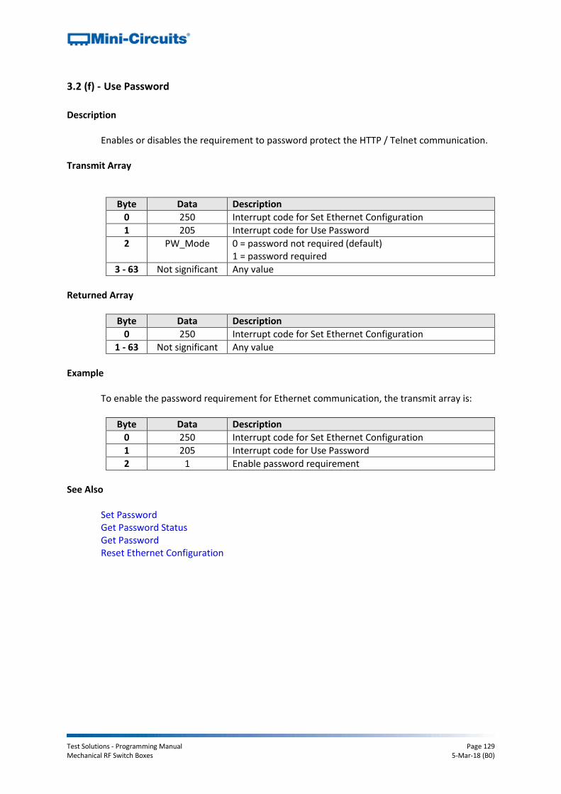
Test Solutions - Programming Manual Page 129 Mechanical RF Switch Boxes 5-Mar-18 (B0)
3.2 (f) - Use Password
Description
Enables or disables the requirement to password protect the HTTP / Telnet communication. Transmit Array
Byte Data Description
0 250 Interrupt code for Set Ethernet Configuration
1 205 Interrupt code for Use Password
2 PW_Mode 0 = password not required (default) 1 = password required
3 - 63 Not significant Any value
Returned Array
Byte Data Description
0 250 Interrupt code for Set Ethernet Configuration
1 - 63 Not significant Any value
Example
To enable the password requirement for Ethernet communication, the transmit array is:
Byte Data Description
0 250 Interrupt code for Set Ethernet Configuration
1 205 Interrupt code for Use Password
2 1 Enable password requirement
See Also
Set Password Get Password Status Get Password Reset Ethernet Configuration
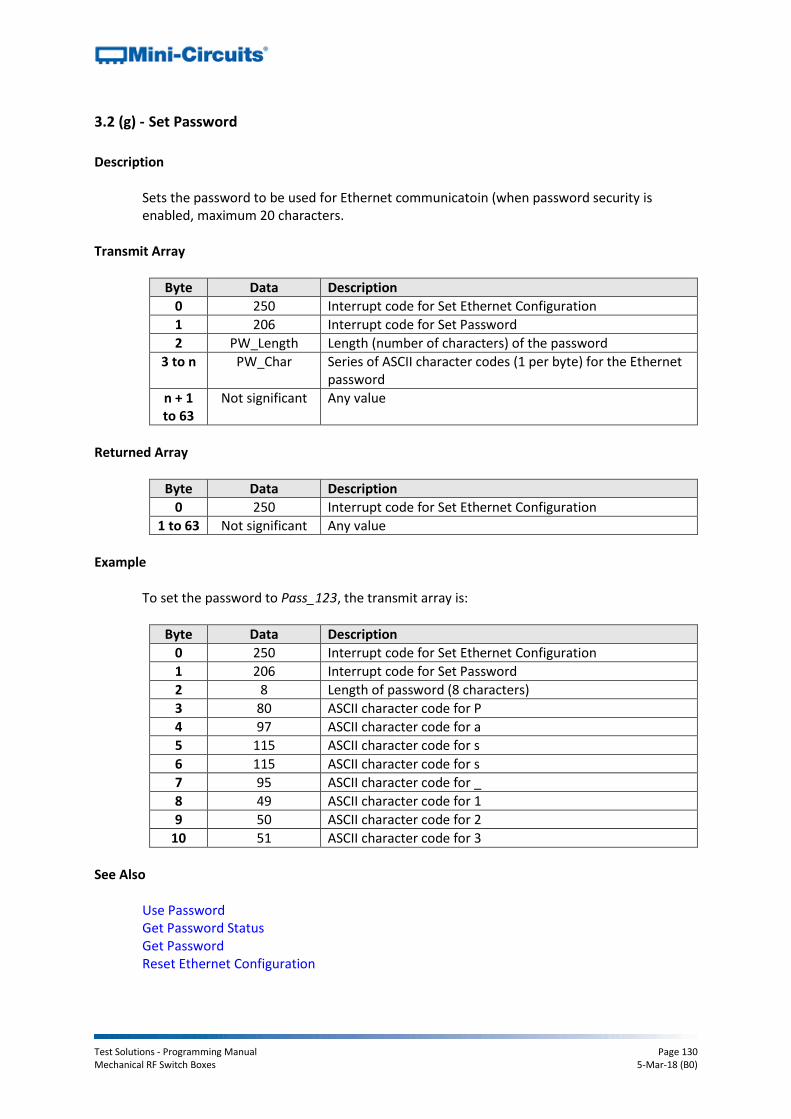
Test Solutions - Programming Manual Page 130 Mechanical RF Switch Boxes 5-Mar-18 (B0)
3.2 (g) - Set Password
Description
Sets the password to be used for Ethernet communicatoin (when password security is enabled, maximum 20 characters.
Transmit Array
Byte Data Description
0 250 Interrupt code for Set Ethernet Configuration
1 206 Interrupt code for Set Password
2 PW_Length Length (number of characters) of the password
3 to n PW_Char Series of ASCII character codes (1 per byte) for the Ethernet password
n + 1 to 63
Not significant Any value
Returned Array
Byte Data Description
0 250 Interrupt code for Set Ethernet Configuration
1 to 63 Not significant Any value
Example
To set the password to Pass_123, the transmit array is:
Byte Data Description
0 250 Interrupt code for Set Ethernet Configuration
1 206 Interrupt code for Set Password
2 8 Length of password (8 characters)
3 80 ASCII character code for P
4 97 ASCII character code for a
5 115 ASCII character code for s
6 115 ASCII character code for s
7 95 ASCII character code for _
8 49 ASCII character code for 1
9 50 ASCII character code for 2
10 51 ASCII character code for 3
See Also
Use Password Get Password Status Get Password Reset Ethernet Configuration

Test Solutions - Programming Manual Page 131 Mechanical RF Switch Boxes 5-Mar-18 (B0)
3.2 (h) - Use DHCP
Description
Enables or disables DHCP (dynamic host control protocol). With DHCP enabled, the attenuators Ethernet / IP configuration is assigned by the network and any user defined static IP settings are ignored. With DHCP disabled, the user defined static IP settings are used.
Transmit Array
Byte Data Description
0 250 Interrupt code for Set Ethernet Configuration
1 205 Interrupt code for Use DHCP
2 DHCP_Mode 0 = DCHP disabled (static IP settings in use) 1 = DHCP enabled (default - dynamic IP in use)
3 - 63 Not significant Any value
Returned Array
Byte Data Description
0 250 Interrupt code for Set Ethernet Configuration
1 - 63 Not significant Any value
Example
To enable DHCP for Ethernet communication, the transmit array is:
Byte Data Description
0 250 Interrupt code for Set Ethernet Configuration
1 205 Interrupt code for Use DHCP
2 1 Enable DHCP
See Also
Use DHCP Get DHCP Status Get Dynamic Ethernet Configuration Reset Ethernet Configuration

Test Solutions - Programming Manual Page 132 Mechanical RF Switch Boxes 5-Mar-18 (B0)
3.2 (i) - Get Static IP Address
Description
Gets the static IP address (configured by the user) to be used when DHCP (dynamic host control protocol) is disabled.
Transmit Array
Byte Data Description
0 251 Interrupt code for Get Ethernet Configuration
1 201 Interrupt code for Get IP Address
2 - 63 Not significant Any value
Returned Array
Byte Data Description
0 251 Interrupt code for Get Ethernet Configuration
1 IP_Byte0 First byte of IP address
2 IP_Byte1 Second byte of IP address
3 IP_Byte2 Third byte of IP address
4 IP_Byte3 Fourth byte of IP address
5 - 63 Not significant Any value
Example
The following returned array would indicate that a static IP address of 192.168.100.100 has been configured:
Byte Data Description
0 251 Interrupt code for Get Ethernet Configuration
1 192 First byte of IP address
2 168 Second byte of IP address
3 100 Third byte of IP address
4 100 Fourth byte of IP address
See Also
Use DHCP Set Static IP Address

Test Solutions - Programming Manual Page 133 Mechanical RF Switch Boxes 5-Mar-18 (B0)
3.2 (j) - Get Static Subnet Mask
Description
Gets the subnet mask (configured by the user) to be used when DHCP (dynamic host control protocol) is disabled.
Transmit Array
Byte Data Description
0 251 Interrupt code for Get Ethernet Configuration
1 202 Interrupt code for Get Subnet Mask
2 - 63 Not significant Any value
Returned Array
Byte Data Description
0 251 Interrupt code for Get Ethernet Configuration
1 IP_Byte0 First byte of subnet mask
2 IP_Byte1 Second byte of subnet mask
3 IP_Byte2 Third byte of subnet mask
4 IP_Byte3 Fourth byte of subnet mask
5 - 63 Not significant Any value
Example
The following returned array would indicate that a subnet mask of 255.255.255.0 has been configured:
Byte Data Description
0 251 Interrupt code for Get Ethernet Configuration
1 255 First byte of subnet mask
2 255 Second byte of subnet mask
3 255 Third byte of subnet mask
4 0 Fourth byte of subnet mask
See Also
Use DHCP Set Static Subnet Mask

Test Solutions - Programming Manual Page 134 Mechanical RF Switch Boxes 5-Mar-18 (B0)
3.2 (k) - Get Static Network Gateway
Description
Gets the static IP address (configured by the user) of the network gateway to be used when DHCP (dynamic host control protocol) is disabled.
Transmit Array
Byte Data Description
0 251 Interrupt code for Get Ethernet Configuration
1 203 Interrupt code for Get Network Gateway
2 - 63 Not significant Any value
Returned Array
Byte Data Description
0 251 Interrupt code for Get Ethernet Configuration
1 IP_Byte0 First byte of IP address
2 IP_Byte1 Second byte of IP address
3 IP_Byte2 Third byte of IP address
4 IP_Byte3 Fourth byte of IP address
5 - 63 Not significant Any value
Example
The following returned array would indicate that a network gateway IP address of 192.168.100.0 has been configured:
Byte Data Description
0 251 Interrupt code for Get Ethernet Configuration
1 192 First byte of IP address
2 168 Second byte of IP address
3 100 Third byte of IP address
4 0 Fourth byte of IP address
See Also
Use DHCP Set Static Network Gateway
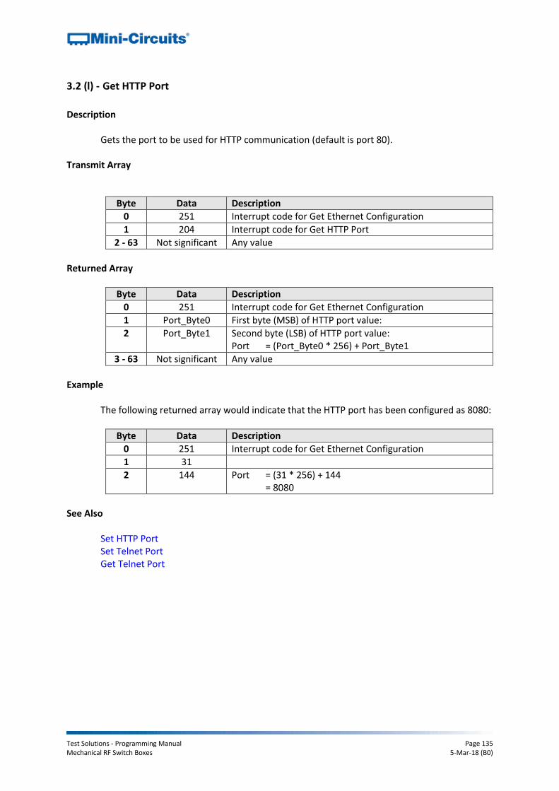
Test Solutions - Programming Manual Page 135 Mechanical RF Switch Boxes 5-Mar-18 (B0)
3.2 (l) - Get HTTP Port
Description
Gets the port to be used for HTTP communication (default is port 80). Transmit Array
Byte Data Description
0 251 Interrupt code for Get Ethernet Configuration
1 204 Interrupt code for Get HTTP Port
2 - 63 Not significant Any value
Returned Array
Byte Data Description
0 251 Interrupt code for Get Ethernet Configuration
1 Port_Byte0 First byte (MSB) of HTTP port value:
2 Port_Byte1 Second byte (LSB) of HTTP port value: Port = (Port_Byte0 * 256) + Port_Byte1
3 - 63 Not significant Any value
Example
The following returned array would indicate that the HTTP port has been configured as 8080:
Byte Data Description
0 251 Interrupt code for Get Ethernet Configuration
1 31
2 144 Port = (31 * 256) + 144 = 8080
See Also
Set HTTP Port Set Telnet Port Get Telnet Port

Test Solutions - Programming Manual Page 136 Mechanical RF Switch Boxes 5-Mar-18 (B0)
3.2 (m) - Get Telnet Port
Description
Gets the port to be used for Telnet communication (default is port 23). Transmit Array
Byte Data Description
0 251 Interrupt code for Get Ethernet Configuration
1 214 Interrupt code for Get Telnet Port
2 - 63 Not significant Any value
Returned Array
Byte Data Description
0 251 Interrupt code for Get Ethernet Configuration
1 Port_Byte0 First byte (MSB) of Telnet port value:
2 Port_Byte1 Second byte (LSB) of Telnet port value: Port = (Port_Byte0 * 256) + Port_Byte1
3 - 63 Not significant Any value
Example
The following returned array would indicate that the Telnet port has been configured as 22:
Byte Data Description
0 251 Interrupt code for Get Ethernet Configuration
1 0
2 22 Port = (0 * 256) + 22 = 22
See Also
Set HTTP Port Set Telnet Port Get HTTP Port
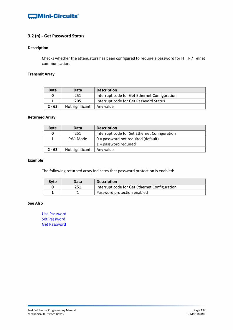
Test Solutions - Programming Manual Page 137 Mechanical RF Switch Boxes 5-Mar-18 (B0)
3.2 (n) - Get Password Status
Description
Checks whether the attenuators has been configured to require a password for HTTP / Telnet communication.
Transmit Array
Byte Data Description
0 251 Interrupt code for Get Ethernet Configuration
1 205 Interrupt code for Get Password Status
2 - 63 Not significant Any value
Returned Array
Byte Data Description
0 251 Interrupt code for Set Ethernet Configuration
1 PW_Mode 0 = password not required (default) 1 = password required
2 - 63 Not significant Any value
Example
The following returned array indicates that password protection is enabled:
Byte Data Description
0 251 Interrupt code for Get Ethernet Configuration
1 1 Password protection enabled
See Also
Use Password Set Password Get Password

Test Solutions - Programming Manual Page 138 Mechanical RF Switch Boxes 5-Mar-18 (B0)
3.2 (o) - Get Password
Description
Gets the password to be used for Ethernet communicatoin (when password security is enabled, maximum 20 characters.
Transmit Array
Byte Data Description
0 251 Interrupt code for Get Ethernet Configuration
1 206 Interrupt code for Get Password
2 to 63 Not significant Any value
Returned Array
Byte Data Description
0 251 Interrupt code for Get Ethernet Configuration
1 PW_Length Length (number of characters) of the password
2 to n PW_Char Series of ASCII character codes (1 per byte) for the Ethernet password
n to 63 Not significant Any value
Example
The following returned array indicated that the password has been set to Pass_123:
Byte Data Description
0 251 Interrupt code for Get Ethernet Configuration
1 8 Length of password (8 characters)
2 80 ASCII character code for P
3 97 ASCII character code for a
4 115 ASCII character code for s
5 115 ASCII character code for s
6 95 ASCII character code for _
7 49 ASCII character code for 1
8 50 ASCII character code for 2
9 51 ASCII character code for 3
See Also
Use Password Set Password Get Password Status

Test Solutions - Programming Manual Page 139 Mechanical RF Switch Boxes 5-Mar-18 (B0)
3.2 (p) - Get DHCP Status
Description
Checks whether DHCP (dynamic host control protocol) is enabled or disabled. With DHCP enabled, the attenuators Ethernet / IP configuration is assigned by the network and any user defined static IP settings are ignored. With DHCP disabled, the user defined static IP settings are used.
Transmit Array
Byte Data Description
0 251 Interrupt code for Get Ethernet Configuration
1 207 Interrupt code for Get DHCP Status
2 - 63 Not significant Any value
Returned Array
Byte Data Description
0 251 Interrupt code for Set Ethernet Configuration
1 DCHP_Mode 0 = DCHP disabled (static IP settings in use) 1 = DHCP enabled (default - dynamic IP in use)
2 - 63 Not significant Any value
Example
The following returned array indicates that DHCP is enabled:
Byte Data Description
0 251 Interrupt code for Get Ethernet Configuration
1 1 DHCP enabled
See Also
Use DHCP Get Dynamic Ethernet Configuration

Test Solutions - Programming Manual Page 140 Mechanical RF Switch Boxes 5-Mar-18 (B0)
3.2 (q) - Get Dynamic Ethernet Configuration
Description
Returns the IP address, subnet mask and default gateway currently used by the programmable attenuator. If DHCP is enabled then these values are assigned by the network DHCP server. If DHCP is disabled then these values are the static configuration defined by the user.
Transmit Array
Byte Data Description
0 253 Interrupt code for Get Dynamic Ethernet Configuration
1 - 63 Not significant Any value
Returned Array
Byte Data Description
0 253 Interrupt code for Get Dynamic Ethernet Configuration
1 IP_Byte0 First byte of IP address
2 IP_Byte1 Second byte of IP address
3 IP_Byte2 Third byte of IP address
4 IP_Byte3 Fourth byte of IP address
5 SM_Byte0 First byte of subnet mask
6 SM_Byte1 Second byte of subnet mask
7 SM_Byte2 Third byte of subnet mask
8 SM_Byte3 Fourth byte of subnet mask
9 NG_Byte0 First byte of network gateway IP address
10 NG_Byte1 Second byte of network gateway IP address
11 NG_Byte2 Third byte of network gateway IP address
12 NG_Byte3 Fourth byte of network gateway IP address
13 - 63 Not significant Any value

Test Solutions - Programming Manual Page 141 Mechanical RF Switch Boxes 5-Mar-18 (B0)
Example
The following returned array would indicate the below Ethernet configuration is active:
IP Address: 192.168.100.100
Subnet Mask: 255.255.255.0
Network Gateway: 192.168.100.0
Byte Data Description
0 253 Interrupt code for Get Dynamic Ethernet Configuration
1 192 First byte of IP address
2 168 Second byte of IP address
3 100 Third byte of IP address
4 100 Fourth byte of IP address
5 255 First byte of subnet mask
6 255 Second byte of subnet mask
7 255 Third byte of subnet mask
8 0 Fourth byte of subnet mask
9 192 First byte of network gateway IP address
10 168 Second byte of network gateway IP address
11 100 Third byte of network gateway IP address
12 0 Fourth byte of network gateway IP address
See Also
Use DHCP Get DHCP Status

Test Solutions - Programming Manual Page 142 Mechanical RF Switch Boxes 5-Mar-18 (B0)
3.2 (r) - Get MAC Address
Description
Returns the MAC address of the programmable attenuator. Transmit Array
Byte Data Description
0 252 Interrupt code for Get MAC Address
1 - 63 Not significant Any value
Returned Array
Byte Data Description
0 252 Interrupt code for Get MAC Address
1 MAC_Byte0 First byte of MAC address
2 MAC_Byte1 Second byte of MAC address
3 MAC_Byte2 Third byte of MAC address
4 MAC_Byte3 Fourth byte of MAC address
5 MAC_Byte4 Fifth byte of MAC address
6 MAC_Byte5 Sixth byte of MAC address
7 - 63 Not significant Any value
Example
The following returned array would indicate a MAC address (in decimal notation) of 11:47:165:103:137:171:
Byte Data Description
0 252 Interrupt code for Get MAC Address
1 11 First byte of MAC address
2 47 Second byte of MAC address
3 165 Third byte of MAC address
4 103 Fourth byte of MAC address
5 137 Fifth byte of MAC address
6 171 Sixth byte of MAC address
See Also
Get Dynamic Ethernet Configuration

Test Solutions - Programming Manual Page 143 Mechanical RF Switch Boxes 5-Mar-18 (B0)
3.2 (s) - Reset Ethernet Configuration
Description
Forces the programmable attenuator to resest and adopt the latest Ethernet configuration. Must be sent after any changes are made to the configuration.
Transmit Array
Byte Data Description
0 101 Reset Ethernet configuration sequence
1 101 Reset Ethernet configuration sequence
2 102 Reset Ethernet configuration sequence
3 103 Reset Ethernet configuration sequence
4 - 63 Not significant Any value
Returned Array
Byte Data Description
0 101 Confirmation of reset Ethernet configuration sequence
1 - 63 Not significant Any value

Test Solutions - Programming Manual Page 144 Mechanical RF Switch Boxes 5-Mar-18 (B0)
4 - Ethernet Control over IP Networks
The Mini-Circuits “RC” switch matrix models have an additional RJ45 connector option for remote control over Ethernet TCP/IP networks. HTTP (Get/Post commands) and Telnet communication are supported. UDP transmission is also supported for discovering available switch matrix devices on the network. The device can be configured manually with a static IP address or automatically by the network using DHCP (Dynamic Host Control Protocol):
Dynamic IP (factory default setting) o Subnet Mask, Network Gateway and local IP Address are assigned by the
network server on each connection o The only user controllable parameters are:
TCP/IP Port (the port used for HTTP communication with the network; default is port)
Password (up to 20 characters; default is no password)
Static IP o All parameters must be specified by the user:
IP Address (must be a legal and unique address on the local network) Subnet Mask (subnet mask of the local network) Network gateway (the IP address of the network gateway/router) TCP/IP port (the port used for HTTP communication with the network;
default is port 80) Password (up to 20 characters; default is no password)
Notes:
1. The TCP/IP port must be included in every HTTP command to the switch unless the default port 80 is used
2. Port 23 is reserved for Telnet communication
4.1 - Configuring Ethernet Settings via USB
The switch matrix must be connected via the USB interface in order to configure the Ethernet settings. Following initial configuration, the device can be controlled via the Ethernet interface with no further need for a USB connection. The API DLL provides the necessary functions for configuring the Ethernet settings via USB, please see Description of DLL Functions for Ethernet Configuration for details.

Test Solutions - Programming Manual Page 145 Mechanical RF Switch Boxes 5-Mar-18 (B0)
4.2 - Ethernet Communication Methodology
Communication over Ethernet can be accomplished using HTTP Get/Post commands or Telnet communication. These communication protocols are both commonly supported and simple to implement in most programming languages. Any Internet browser can be used as a console/tester for HTTP control by typing the commands/queries directly into the address bar.
4.2 (a) - Setting Switch States Using HTTP
The basic format of the HTTP command to set the switch is:
http://ADDRESS:PORT/PWD;COMMAND Where
http:// is required
ADDRESS = IP address (required)
PORT = TCP/IP port (can be omitted if port 80 is used)
PWD = Password (can be omitted if password security is not enabled)
COMMAND = Command to send to the switch Example 1:
http://192.168.100.100:800/PWD=123;SETA=1 Explanation:
The switch has IP address 192.168.100.100 and uses port 800
Password security is enabled and set to “123”
The command is to set switch A to state 1 (see below for the full explanation of all commands/queries)
Example 2:
http://10.10.10.10/SETB=0 Explanation:
The switch has IP address 10.10.10.10 and uses the default port 80
Password security is disabled
The command is to set switch B to state 0 (see below for the full explanation of all commands/queries)
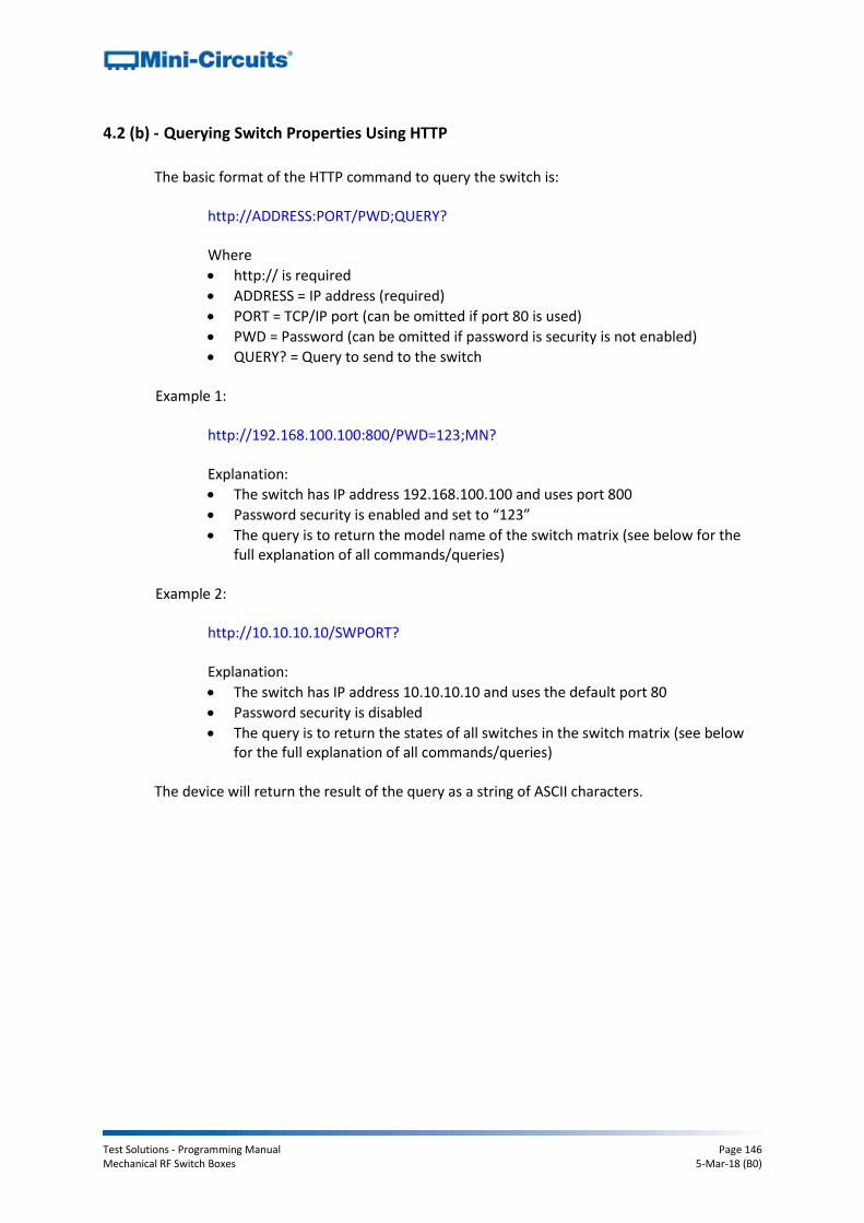
Test Solutions - Programming Manual Page 146 Mechanical RF Switch Boxes 5-Mar-18 (B0)
4.2 (b) - Querying Switch Properties Using HTTP
The basic format of the HTTP command to query the switch is:
http://ADDRESS:PORT/PWD;QUERY? Where
http:// is required
ADDRESS = IP address (required)
PORT = TCP/IP port (can be omitted if port 80 is used)
PWD = Password (can be omitted if password is security is not enabled)
QUERY? = Query to send to the switch Example 1:
http://192.168.100.100:800/PWD=123;MN? Explanation:
The switch has IP address 192.168.100.100 and uses port 800
Password security is enabled and set to “123”
The query is to return the model name of the switch matrix (see below for the full explanation of all commands/queries)
Example 2:
http://10.10.10.10/SWPORT? Explanation:
The switch has IP address 10.10.10.10 and uses the default port 80
Password security is disabled
The query is to return the states of all switches in the switch matrix (see below for the full explanation of all commands/queries)
The device will return the result of the query as a string of ASCII characters.

Test Solutions - Programming Manual Page 147 Mechanical RF Switch Boxes 5-Mar-18 (B0)
4.2 (c) - Communication Using Telnet
Communication with the device is started by creating a Telnet connection to the switch IP address. On successful connection the “line feed” character will be returned. If the switch matrix has a password enabled then this must be sent as the first command after connection. The full list of all commands and queries is detailed in the following sections. A basic example of the Telnet communication structure using the Windows Telnet Client is summarized below: 1) Set up Telnet connection to a switch matrix with IP address 192.168.9.60:
2) The “line feed” character is returned indicating the connection was successful:
3) The password (if enabled) must be sent as the first command:
The password must be entered in the format PWD=password;
A return value of 1 indicates success:
4) Any number of commands and queries can be sent as needed:
5) Use the control and "]" keys to end the session.

Test Solutions - Programming Manual Page 148 Mechanical RF Switch Boxes 5-Mar-18 (B0)
4.3 - Device Discovery Using UDP
In addition to HTTP and Telnet, the RC series of Ethernet controlled switch matrices also provide limited support of the UDP protocol for the purpose of “device discovery.” This allows a user to request the IP address and configuration of all Mini-Circuits RC switch matrices connected on the network; full control of those units is then accomplished using HTTP or Telnet, as detailed previously. Alternatively, the IP configuration can be identified or changed by connecting the switch matrix with the USB interface (see Configuring Ethernet Settings). Note: UDP is a simple transmission protocol that provides no method for error correction or guarantee of receipt.
UDP Ports Mini-Circuits’ RC switch matrices are configured to listen on UDP port 4950 and answer on UDP port 4951. Communication on these ports must be allowed through the computer’s firewall in order to use UDP for device discovery. If the switch’s IP address is already known it is not necessary to use UDP.
Transmission The command MCLRFSWITCH? should be broadcast to the local network using UDP protocol on port 4950.
Receipt All Mini-Circuits RC switch matrices that receive the request will respond with the following information (each field separated by CrLf) on port 4951:
Model Name
Serial Number
IP Address/Port
Subnet Mask
Network Gateway
Mac Address

Test Solutions - Programming Manual Page 149 Mechanical RF Switch Boxes 5-Mar-18 (B0)
Example Sent Data: MCLRFSWITCH? Received Data:
Model Name: RC-2SPDT-A18 Serial Number: 11302120001 IP Address=192.168.9.101 Port: 80 Subnet Mask=255.255.0.0 Network Gateway=192.168.9.0 Mac Address=D0-73-7F-82-D8-01 Model Name: RC-2SPDT-A18 Serial Number: 11302120002 IP Address=192.168.9.102 Port: 80 Subnet Mask=255.255.0.0 Network Gateway=192.168.9.0 Mac Address=D0-73-7F-82-D8-02 Model Name: RC-2SPDT-A18 Serial Number: 11302120003 IP Address=192.168.9.103 Port: 80 Subnet Mask=255.255.0.0 Network Gateway=192.168.9.0 Mac Address=D0-73-7F-82-D8-03
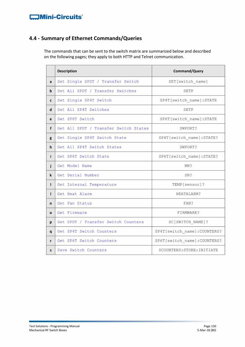
Test Solutions - Programming Manual Page 150 Mechanical RF Switch Boxes 5-Mar-18 (B0)
4.4 - Summary of Ethernet Commands/Queries
The commands that can be sent to the switch matrix are summarized below and described on the following pages; they apply to both HTTP and Telnet communication.
Description Command/Query
a Set Single SPDT / Transfer Switch SET[switch_name]
b Set All SPDT / Transfer Switches SETP
c Set Single SP4T Switch SP4T[switch_name]:STATE
d Set All SP4T Switches SETP
e Set SP6T Switch SP6T[switch_name]:STATE
f Get All SPDT / Transfer Switch States SWPORT?
g Get Single SP4T Switch State SP4T[switch_name]:STATE?
h Get All SP4T Switch States SWPORT?
i Get SP6T Switch State SP6T[switch_name]:STATE?
j Get Model Name MN?
k Get Serial Number SN?
l Get Internal Temperature TEMP[sensor]?
l Get Heat Alarm HEATALARM?
n Get Fan Status FAN?
o Get Firmware FIRMWARE?
p Get SPDT / Transfer Switch Counters SC[SWITCH_NAME]?
q Get SP4T Switch Counters SP4T[switch_name]:COUNTERS?
r Get SP6T Switch Counters SP6T[switch_name]:COUNTERS?
s Save Switch Counters SCOUNTERS:STORE:INITIATE

Test Solutions - Programming Manual Page 151 Mechanical RF Switch Boxes 5-Mar-18 (B0)
4.5 - Description of Ethernet Commands/Queries
4.5 (a) - Set Single SPDT / Transfer Switch
Description
Sets an individual switch within an SPDT or transfer switch matrix whilst leaving any other switches unchanged.
Applies To
Model Serial Numbers
RC-xSPDT-A18 All serial numbers
RC-xMTS-18 All serial numbers
ZTRC-xSPDT-A18 All serial numbers
Command
SET[switch]=[state]
Parameter Description [switch] The individual switch (A-H) to be controlled. For example:
SETA sets switch A SETB sets switch B
[state] The state (0 or 1) into which the switch should be set: 2 = Connect Com port to port 1 (SPDT)
Connect J1 <> J3 and J2 <> J4 (transfer switch) 3 = Connect Com port to port 2
Connect J1 <> J2 and J3 <> J4 (transfer switch)
Return Value
Value Description
0 Command failed
1 Command completed successfully
Examples
Set switch A to state 1 (Com port connected to port 2):
SETA=1 Set switch C to state 0 (Com port connected to port 1):
SETC=0
See Also
Set All SPDT / Transfer Switches Get All SPDT / Transfer Switch States Set All SP4T Switches Set SP6T Switch
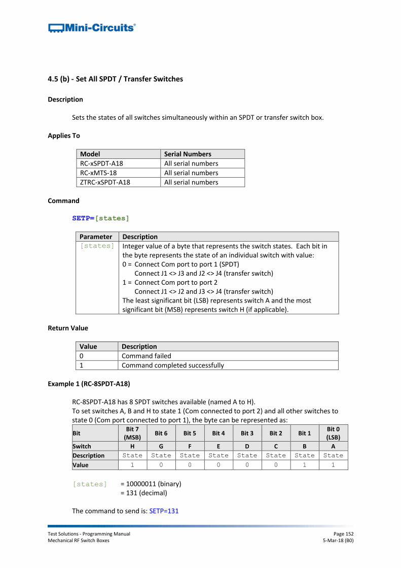
Test Solutions - Programming Manual Page 152 Mechanical RF Switch Boxes 5-Mar-18 (B0)
4.5 (b) - Set All SPDT / Transfer Switches
Description
Sets the states of all switches simultaneously within an SPDT or transfer switch box.
Applies To
Model Serial Numbers
RC-xSPDT-A18 All serial numbers
RC-xMTS-18 All serial numbers
ZTRC-xSPDT-A18 All serial numbers
Command
SETP=[states]
Parameter Description [states] Integer value of a byte that represents the switch states. Each bit in
the byte represents the state of an individual switch with value: 0 = Connect Com port to port 1 (SPDT)
Connect J1 <> J3 and J2 <> J4 (transfer switch) 1 = Connect Com port to port 2
Connect J1 <> J2 and J3 <> J4 (transfer switch) The least significant bit (LSB) represents switch A and the most significant bit (MSB) represents switch H (if applicable).
Return Value
Value Description
0 Command failed
1 Command completed successfully
Example 1 (RC-8SPDT-A18)
RC-8SPDT-A18 has 8 SPDT switches available (named A to H). To set switches A, B and H to state 1 (Com connected to port 2) and all other switches to state 0 (Com port connected to port 1), the byte can be represented as:
Bit Bit 7
(MSB) Bit 6 Bit 5 Bit 4 Bit 3 Bit 2 Bit 1
Bit 0 (LSB)
Switch H G F E D C B A
Description State State State State State State State State
Value 1 0 0 0 0 0 1 1
[states] = 10000011 (binary) = 131 (decimal) The command to send is: SETP=131

Test Solutions - Programming Manual Page 153 Mechanical RF Switch Boxes 5-Mar-18 (B0)
Example 2 (RC-2MTS-18) RC-2MTS-18 has 2 transfer switches available (named A and B). To set both switches to state 1 (J1 <> J2 and J3 <> J4), the byte can be represented as:
Bit Bit 7
(MSB) Bit 6 Bit 5 Bit 4 Bit 3 Bit 2 Bit 1
Bit 0 (LSB)
Switch --- --- --- --- --- --- B A
Description Don’t
care
Don’t
care
Don’t
care
Don’t
care
Don’t
care
Don’t
care State State
Value 0 0 0 0 0 0 1 1
[states] = 00000011 (binary) = 3 (decimal) The command to send is: SETP=3
See Also
Set Single SPDT / Transfer Switch Get All SPDT / Transfer Switch States Set All SP4T Switches Set SP6T Switch Get SPDT Switch States

Test Solutions - Programming Manual Page 154 Mechanical RF Switch Boxes 5-Mar-18 (B0)
4.5 (c) - Set Single SP4T Switch
Description
Sets an individual switch within an SP4T switch matrix whilst leaving any other switches (if applicable) unchanged.
Applies To
Model Requirements
RC-xSP4T-x Firmware C8 or later
Command
SP4T[switch]:STATE:[state]
Parameter Description [switch] The individual switch (A or B) to be controlled
[state] The switch state to set:
0 = All ports disconnected 1 = Connect Com port to port 1 2 = Connect Com port to port 2 3 = Connect Com port to port 3 4 = Connect Com port to port 4
Return Value
Value Description
0 Command failed
1 Command completed successfully
Examples
Set switch A to state 3 (Com port connected to port 3):
SP4TA:STATE:3 Set switch B to state 0 (all ports disconnected):
SP4TB:STATE:0
See Also

Test Solutions - Programming Manual Page 155 Mechanical RF Switch Boxes 5-Mar-18 (B0)
4.5 (d) - Set All SP4T Switches
Description
Sets all switches within an SP4T switch box to a specified state.
Applies To
Model Serial Numbers
RC-xSP4T-x All serial numbers
Command
SETP=[state]
Parameter Description [state] Integer value of a byte that represents the switch states. Each bit in
the byte corresponds to an input/output port, with the 4 least significant bits (LSB) corresponding to switch A (all models) and the 4 most significant bits (MSB) corresponding to switch B (RC-2SP4T-A18 only). Switch A (all models): If Bits 0 to 3 = 0, switch A has all ports disconnected If Bit 0 = 1, switch A has Com connected to port 1 If Bit 1 = 1, switch A has Com connected to port 2 If Bit 2 = 1, switch A has Com connected to port 3 If Bit 3 = 1, switch A has Com connected to port 4 Switch B (RC-2SP4T-A18 only): If Bits 4 to 7 = 0, switch B has all ports disconnected If Bit 4 = 1, switch B has Com connected to port 1 If Bit 5 = 1, switch B has Com connected to port 2 If Bit 6 = 1, switch B has Com connected to port 3 If Bit 7 = 1, switch B has Com connected to port 4
Return Value
Value Description
0 Command failed
1 Command completed successfully
4 Switch not set (invalid switch state requested)

Test Solutions - Programming Manual Page 156 Mechanical RF Switch Boxes 5-Mar-18 (B0)
Example 1 (RC-1SP4T-A18)
Bits 4 to 7 refer to switch B which is not applicable for this model, they can therefore take any value. To set switch A to position 3 (connecting Com port to port 3); the full byte could be represented as:
Bit Bit 7
(MSB) Bit 6 Bit 5 Bit 4 Bit 3 Bit 2 Bit 1
Bit 0 (LSB)
Switch --- Switch A
Description Don’t
care
Don’t
care
Don’t
care
Don’t
care Port 4 Port 3 Port 2 Port 1
Value 0 0 0 0 0 1 0 0
[state] = 00000100 (binary) = 4 (decimal) The command to send is: SETP=4
Example 2 (RC-2SP4T-A18)
To set switch A to position 2 (connecting Com port to port 2) and switch B to position 4 (connecting Com port to port 4), the full byte should be:
Bit Bit 7
(MSB) Bit 6 Bit 5 Bit 4 Bit 3 Bit 2 Bit 1
Bit 0 (LSB)
Switch Switch B Switch A
Description Port 4 Port 3 Port 2 Port 1 Port 4 Port 3 Port 2 Port 1
Value 1 0 0 0 0 0 1 0
[state] = 10000010 (binary) = 130 (decimal) The command to send is: SETP=130
See Also
Set All SPDT Switches Set Single SP4T Switch Set SP6T Switch Get SP4T Switch States
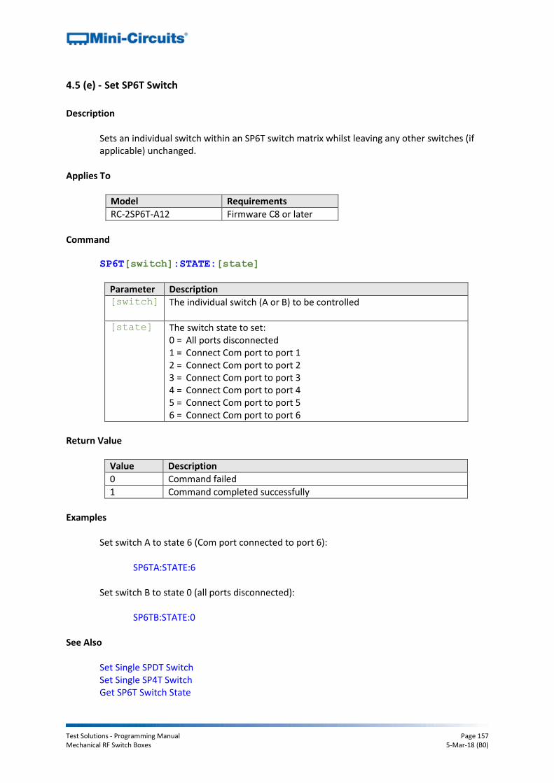
Test Solutions - Programming Manual Page 157 Mechanical RF Switch Boxes 5-Mar-18 (B0)
4.5 (e) - Set SP6T Switch
Description
Sets an individual switch within an SP6T switch matrix whilst leaving any other switches (if applicable) unchanged.
Applies To
Model Requirements
RC-2SP6T-A12 Firmware C8 or later
Command
SP6T[switch]:STATE:[state]
Parameter Description [switch] The individual switch (A or B) to be controlled
[state] The switch state to set:
0 = All ports disconnected 1 = Connect Com port to port 1 2 = Connect Com port to port 2 3 = Connect Com port to port 3 4 = Connect Com port to port 4 5 = Connect Com port to port 5 6 = Connect Com port to port 6
Return Value
Value Description
0 Command failed
1 Command completed successfully
Examples
Set switch A to state 6 (Com port connected to port 6):
SP6TA:STATE:6 Set switch B to state 0 (all ports disconnected):
SP6TB:STATE:0
See Also
Set Single SPDT Switch Set Single SP4T Switch Get SP6T Switch State
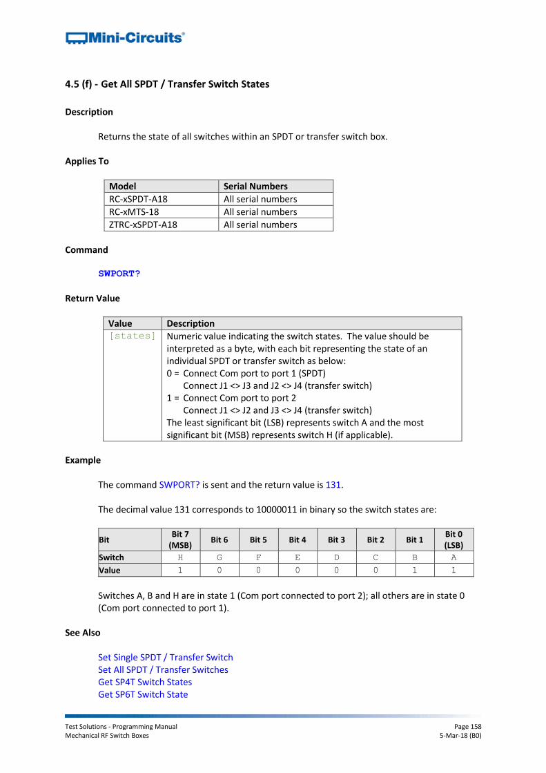
Test Solutions - Programming Manual Page 158 Mechanical RF Switch Boxes 5-Mar-18 (B0)
4.5 (f) - Get All SPDT / Transfer Switch States
Description
Returns the state of all switches within an SPDT or transfer switch box.
Applies To
Model Serial Numbers
RC-xSPDT-A18 All serial numbers
RC-xMTS-18 All serial numbers
ZTRC-xSPDT-A18 All serial numbers
Command
SWPORT?
Return Value
Value Description [states] Numeric value indicating the switch states. The value should be
interpreted as a byte, with each bit representing the state of an individual SPDT or transfer switch as below: 0 = Connect Com port to port 1 (SPDT)
Connect J1 <> J3 and J2 <> J4 (transfer switch) 1 = Connect Com port to port 2
Connect J1 <> J2 and J3 <> J4 (transfer switch) The least significant bit (LSB) represents switch A and the most significant bit (MSB) represents switch H (if applicable).
Example
The command SWPORT? is sent and the return value is 131. The decimal value 131 corresponds to 10000011 in binary so the switch states are:
Bit Bit 7
(MSB) Bit 6 Bit 5 Bit 4 Bit 3 Bit 2 Bit 1
Bit 0 (LSB)
Switch H G F E D C B A
Value 1 0 0 0 0 0 1 1
Switches A, B and H are in state 1 (Com port connected to port 2); all others are in state 0 (Com port connected to port 1).
See Also
Set Single SPDT / Transfer Switch Set All SPDT / Transfer Switches Get SP4T Switch States Get SP6T Switch State
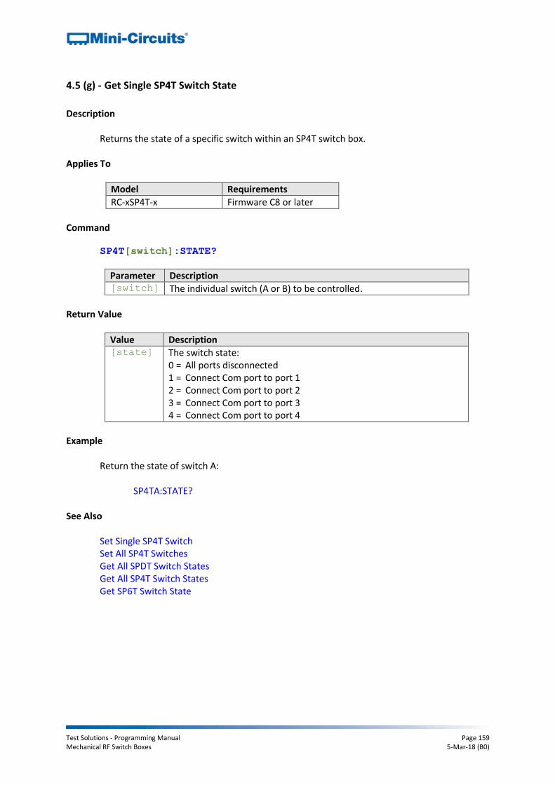
Test Solutions - Programming Manual Page 159 Mechanical RF Switch Boxes 5-Mar-18 (B0)
4.5 (g) - Get Single SP4T Switch State
Description
Returns the state of a specific switch within an SP4T switch box.
Applies To
Model Requirements
RC-xSP4T-x Firmware C8 or later
Command
SP4T[switch]:STATE?
Parameter Description [switch] The individual switch (A or B) to be controlled.
Return Value
Value Description [state] The switch state:
0 = All ports disconnected 1 = Connect Com port to port 1 2 = Connect Com port to port 2 3 = Connect Com port to port 3 4 = Connect Com port to port 4
Example
Return the state of switch A:
SP4TA:STATE? See Also
Set Single SP4T Switch Set All SP4T Switches Get All SPDT Switch States Get All SP4T Switch States Get SP6T Switch State
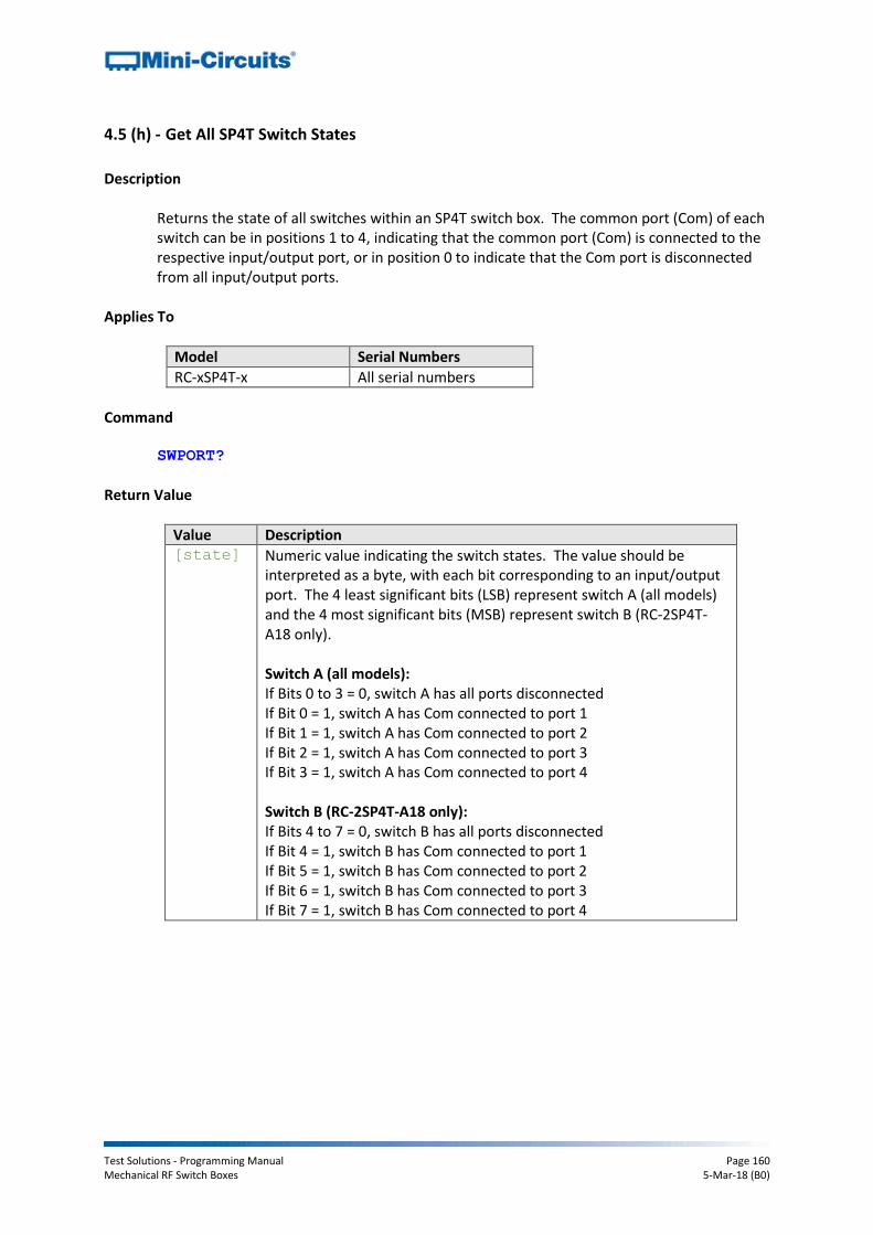
Test Solutions - Programming Manual Page 160 Mechanical RF Switch Boxes 5-Mar-18 (B0)
4.5 (h) - Get All SP4T Switch States
Description
Returns the state of all switches within an SP4T switch box. The common port (Com) of each switch can be in positions 1 to 4, indicating that the common port (Com) is connected to the respective input/output port, or in position 0 to indicate that the Com port is disconnected from all input/output ports.
Applies To
Model Serial Numbers
RC-xSP4T-x All serial numbers
Command
SWPORT?
Return Value
Value Description [state] Numeric value indicating the switch states. The value should be
interpreted as a byte, with each bit corresponding to an input/output port. The 4 least significant bits (LSB) represent switch A (all models) and the 4 most significant bits (MSB) represent switch B (RC-2SP4T-A18 only). Switch A (all models): If Bits 0 to 3 = 0, switch A has all ports disconnected If Bit 0 = 1, switch A has Com connected to port 1 If Bit 1 = 1, switch A has Com connected to port 2 If Bit 2 = 1, switch A has Com connected to port 3 If Bit 3 = 1, switch A has Com connected to port 4 Switch B (RC-2SP4T-A18 only): If Bits 4 to 7 = 0, switch B has all ports disconnected If Bit 4 = 1, switch B has Com connected to port 1 If Bit 5 = 1, switch B has Com connected to port 2 If Bit 6 = 1, switch B has Com connected to port 3 If Bit 7 = 1, switch B has Com connected to port 4
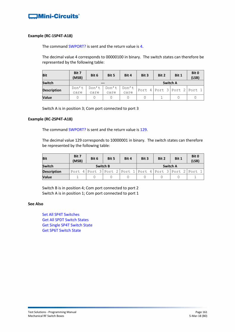
Test Solutions - Programming Manual Page 161 Mechanical RF Switch Boxes 5-Mar-18 (B0)
Example (RC-1SP4T-A18) The command SWPORT? is sent and the return value is 4. The decimal value 4 corresponds to 00000100 in binary. The switch states can therefore be represented by the following table:
Bit Bit 7
(MSB) Bit 6 Bit 5 Bit 4 Bit 3 Bit 2 Bit 1
Bit 0 (LSB)
Switch --- Switch A
Description Don’t
care
Don’t
care Don’t
care Don’t
care Port 4 Port 3 Port 2 Port 1
Value 0 0 0 0 0 1 0 0
Switch A is in position 3; Com port connected to port 3
Example (RC-2SP4T-A18)
The command SWPORT? is sent and the return value is 129. The decimal value 129 corresponds to 10000001 in binary. The switch states can therefore be represented by the following table:
Bit Bit 7
(MSB) Bit 6 Bit 5 Bit 4 Bit 3 Bit 2 Bit 1
Bit 0 (LSB)
Switch Switch B Switch A
Description Port 4 Port 3 Port 2 Port 1 Port 4 Port 3 Port 2 Port 1
Value 1 0 0 0 0 0 0 1
Switch B is in position 4; Com port connected to port 2 Switch A is in position 1; Com port connected to port 1
See Also
Set All SP4T Switches Get All SPDT Switch States Get Single SP4T Switch State Get SP6T Switch State
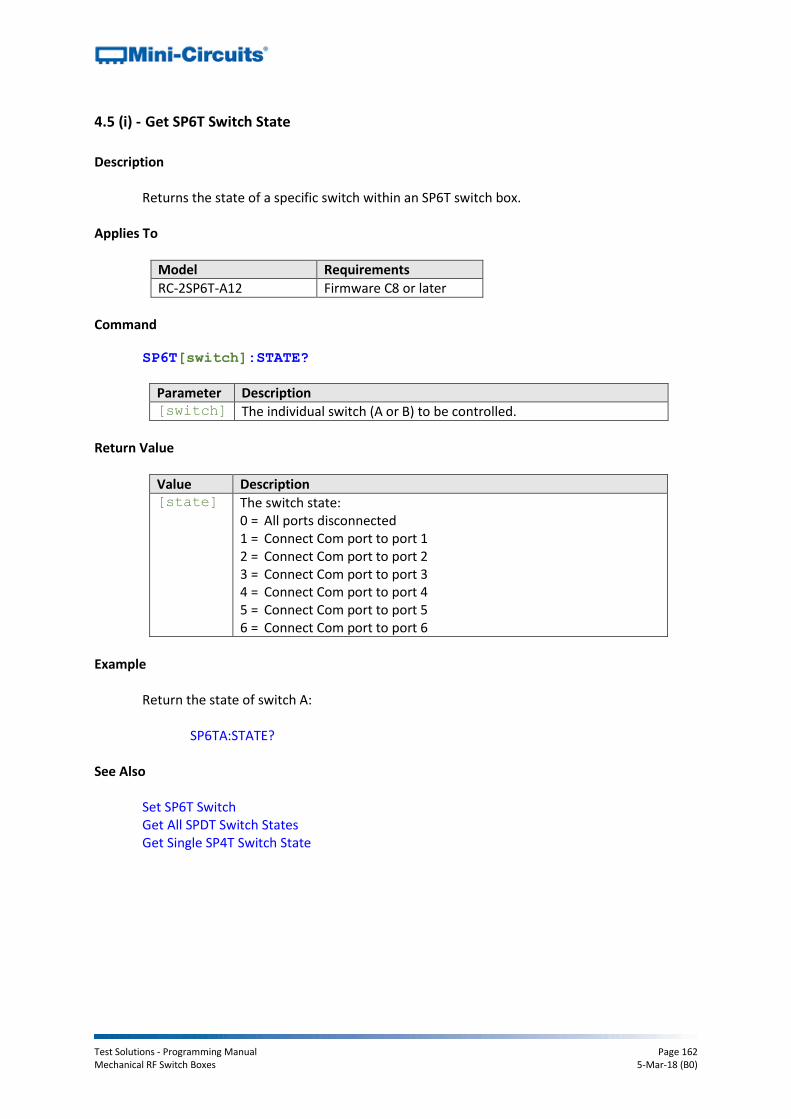
Test Solutions - Programming Manual Page 162 Mechanical RF Switch Boxes 5-Mar-18 (B0)
4.5 (i) - Get SP6T Switch State
Description
Returns the state of a specific switch within an SP6T switch box.
Applies To
Model Requirements
RC-2SP6T-A12 Firmware C8 or later
Command
SP6T[switch]:STATE?
Parameter Description [switch] The individual switch (A or B) to be controlled.
Return Value
Value Description [state] The switch state:
0 = All ports disconnected 1 = Connect Com port to port 1 2 = Connect Com port to port 2 3 = Connect Com port to port 3 4 = Connect Com port to port 4 5 = Connect Com port to port 5 6 = Connect Com port to port 6
Example
Return the state of switch A:
SP6TA:STATE? See Also
Set SP6T Switch Get All SPDT Switch States Get Single SP4T Switch State

Test Solutions - Programming Manual Page 163 Mechanical RF Switch Boxes 5-Mar-18 (B0)
4.5 (j) - Get Model Name
Description
Returns the model name of the connected switch matrix.
Command MN?
Return Value
MN=[model]
Value Description [model] The model name of the switch matrix as a string of ASCII characters
(for example RC-3SPDT-A18).
Example
The command MN? is sent and MN=RC-3SPDT-A18 is returned.
See Also
Get Serial Number

Test Solutions - Programming Manual Page 164 Mechanical RF Switch Boxes 5-Mar-18 (B0)
4.5 (k) - Get Serial Number
Description
Returns the serial number of the connected switch matrix.
Command SN?
Return Value
SN=[serial]
Value Description [serial] The serial number of the switch matrix as a string of ASCII characters
(for example 11305010002).
Example
The command SN? is sent and SN=11305010002 is returned.
See Also
Get Model Name

Test Solutions - Programming Manual Page 165 Mechanical RF Switch Boxes 5-Mar-18 (B0)
4.5 (l) - Get Internal Temperature
Description
Returns the internal temperature measured at 1 of the internal sensors (model dependent):
USB-1SPDT-A18 / RC-1SPDT-A18 (1 sensor)
USB-1SP4T-A18 / RC-1SP4T-A18 (1 sensor)
USB-2SPDT-A18 / RC-2SPDT-A18 (2 sensors)
USB-3SPDT-A18 / RC-3SPDT-A18 (2 sensors)
USB-4SPDT-A18 / RC-4SPDT-A18 (2 sensors)
USB-8SPDT-A18 / RC-8SPDT-A18 (3 sensors)
RC-2SP4T-x (2 sensors)
RC-2SP6T-A12 (2 sensors) Note: Units with serial numbers earlier than 11108010000 may have a different number of sensors than indicated above.
If a sensor that does not exist is polled (for example there is no sensor 2 on USB-1SPDT-A18) the temperature returned will be “+25.00”.
Command
TEMP[sensor]?
Parameter Description [sensor] The internal temperature sensor (1 to 3) to poll. For example:
TEMP1? to poll sensor 1 TEMP2? to poll sensor 2 (model dependent) TEMP3? to poll sensor 3 (model dependent)
Return Value
Value Description [temp] The temperature reading of the specified internal sensor in Degrees
Celsius.
Example
The command TEMP1? is sent and +37.25 is returned.
See Also
Get Heat Alarm Get Fan Status

Test Solutions - Programming Manual Page 166 Mechanical RF Switch Boxes 5-Mar-18 (B0)
4.5 (m) - Get Heat Alarm
Description
Returns an alarm notification if any of the internal temperature sensors exceeds the factory programmed limits (45°C on the PCB or 48°C on the internal switch case).
Command HEATALARM?
Return Value
Value Description [status] Integer value to indicate the heat alarm status:
0 – Device is within normal operating temperature limits 1 – Device temperature has exceeded the recommended limits
Example
The command HEATALARM? is sent and 0 is returned to indicate the device is within normal limits
See Also
Get Internal Temperature Get Fan Status
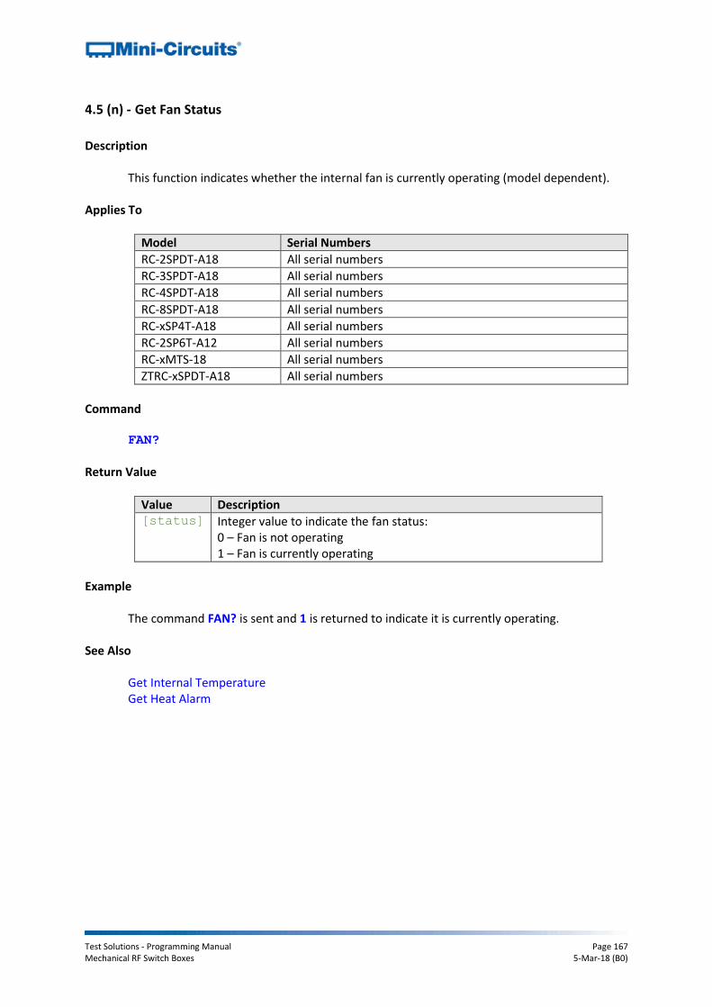
Test Solutions - Programming Manual Page 167 Mechanical RF Switch Boxes 5-Mar-18 (B0)
4.5 (n) - Get Fan Status
Description
This function indicates whether the internal fan is currently operating (model dependent).
Applies To
Model Serial Numbers
RC-2SPDT-A18 All serial numbers
RC-3SPDT-A18 All serial numbers
RC-4SPDT-A18 All serial numbers
RC-8SPDT-A18 All serial numbers
RC-xSP4T-A18 All serial numbers
RC-2SP6T-A12 All serial numbers
RC-xMTS-18 All serial numbers
ZTRC-xSPDT-A18 All serial numbers
Command
FAN?
Return Value
Value Description [status] Integer value to indicate the fan status:
0 – Fan is not operating 1 – Fan is currently operating
Example
The command FAN? is sent and 1 is returned to indicate it is currently operating.
See Also
Get Internal Temperature Get Heat Alarm

Test Solutions - Programming Manual Page 168 Mechanical RF Switch Boxes 5-Mar-18 (B0)
4.5 (o) - Get Firmware
Description
Returns the internal firmware version of the switch box.
Command FIRMWARE?
Return Value
Value Description [firmware] The current firmware version, for example “B3”.
Example
The command FIRMWARE? is sent and C3 is returned.

Test Solutions - Programming Manual Page 169 Mechanical RF Switch Boxes 5-Mar-18 (B0)
4.5 (p) - Get SPDT / Transfer Switch Counters
Description
Returns the number of switching cycles undertaken by a specified SPDT or transfer switch.
Command SC[switch_name]?
Parameter Description [switch_name] The letter indicating the switch name, A to H (model
dependent)
Return Value
Value Description [count] The number of switching cycles undertaken during the life of the
specified switch
Example
The query SCB? and 10500 is returned, indicating that switch B has undertaken 10,500 switching cycles in its lifetime.
See Also
Get SP4T Switch Counters Get SP6T Switch Counters Save Switch Counters
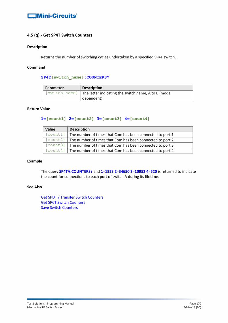
Test Solutions - Programming Manual Page 170 Mechanical RF Switch Boxes 5-Mar-18 (B0)
4.5 (q) - Get SP4T Switch Counters
Description
Returns the number of switching cycles undertaken by a specified SP4T switch.
Command SP4T[switch_name]:COUNTERS?
Parameter Description [switch_name] The letter indicating the switch name, A to B (model
dependent)
Return Value
1=[count1] 2=[count2] 3=[count3] 4=[count4]
Value Description [count1] The number of times that Com has been connected to port 1 [count2] The number of times that Com has been connected to port 2 [count3] The number of times that Com has been connected to port 3 [count4] The number of times that Com has been connected to port 4
Example
The query SP4TA:COUNTERS? and 1=1553 2=34650 3=10952 4=520 is returned to indicate the count for connections to each port of switch A during its lifetime.
See Also
Get SPDT / Transfer Switch Counters Get SP6T Switch Counters Save Switch Counters
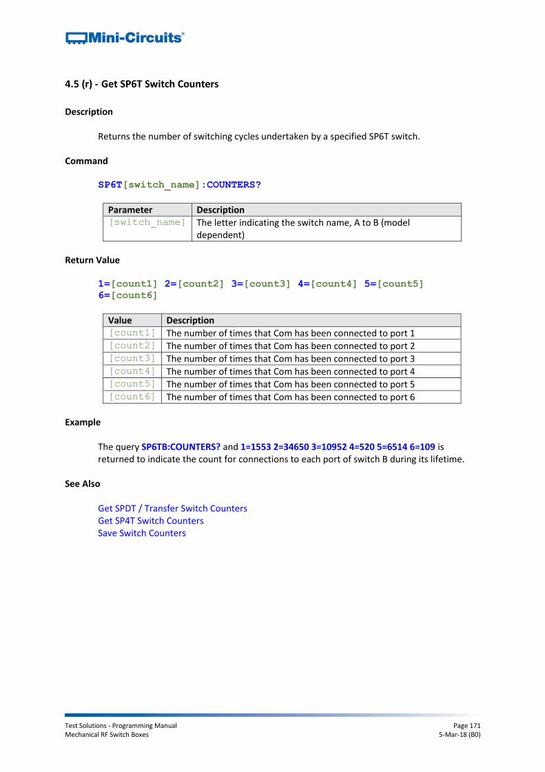
Test Solutions - Programming Manual Page 171 Mechanical RF Switch Boxes 5-Mar-18 (B0)
4.5 (r) - Get SP6T Switch Counters
Description
Returns the number of switching cycles undertaken by a specified SP6T switch.
Command SP6T[switch_name]:COUNTERS?
Parameter Description [switch_name] The letter indicating the switch name, A to B (model
dependent)
Return Value
1=[count1] 2=[count2] 3=[count3] 4=[count4] 5=[count5]
6=[count6]
Value Description [count1] The number of times that Com has been connected to port 1 [count2] The number of times that Com has been connected to port 2 [count3] The number of times that Com has been connected to port 3 [count4] The number of times that Com has been connected to port 4 [count5] The number of times that Com has been connected to port 5 [count6] The number of times that Com has been connected to port 6
Example
The query SP6TB:COUNTERS? and 1=1553 2=34650 3=10952 4=520 5=6514 6=109 is returned to indicate the count for connections to each port of switch B during its lifetime.
See Also
Get SPDT / Transfer Switch Counters Get SP4T Switch Counters Save Switch Counters

Test Solutions - Programming Manual Page 172 Mechanical RF Switch Boxes 5-Mar-18 (B0)
4.5 (s) - Set Power-Up Mode
Description
Sets whether or not the switch box should power-up with all switches in the last remembered state (the last saved state that they occupied prior to DC power being removed). If this mode is not selected then all switches will power-up in the default state. Note: Switch states & counters must be saved prior to powering off the switch box in order to remember the last state.
Requirements
Firmware version D1 or later
Command ONPOWERUP:LASTSTATE[mode]
Parameter Description [mode] ON = All switches will power-up in the last remembered
state OFF = All switches will power-up in the default state:
SP4T & SP6T: All ports disconnected
SPDT: Com connected to port 1
Transfer: J1 <> J3 and J2 <> J4
Return Value
Value Description
0 Command failed
1 Command completed successfully
Example
Use the command ONPOWERUP:LASTSTATE:ON to enable the switch to power up in the last remembered state (be sure to send the SCOUNTERS:STORE:INITIATE command prior to powering off). Use ONPOWERUP:LASTSTATE:OFF to enable the switch to power up in the default states.
See Also
Get Power-Up Mode Save Switch Counters
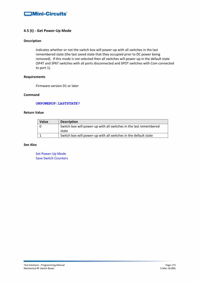
Test Solutions - Programming Manual Page 173 Mechanical RF Switch Boxes 5-Mar-18 (B0)
4.5 (t) - Get Power-Up Mode
Description
Indicates whether or not the switch box will power-up with all switches in the last remembered state (the last saved state that they occupied prior to DC power being removed). If this mode is not selected then all switches will power-up in the default state (SP4T and SP6T switches with all ports disconnected and SPDT switches with Com connected to port 1).
Requirements
Firmware version D1 or later
Command ONPOWERUP:LASTSTATE?
Return Value
Value Description
0 Switch box will power-up with all switches in the last remembered state
1 Switch box will power-up with all switches in the default state
See Also
Set Power-Up Mode Save Switch Counters

Test Solutions - Programming Manual Page 174 Mechanical RF Switch Boxes 5-Mar-18 (B0)
4.5 (u) - Save Switch Counters & States
Description
Transfers the latest switch counters and switch states from temporary to permanent memory. During normal operation, this data is internally stored in volatile memory but automatically updated into permanent memory every 3 minutes. This command should be sent following completion of all switching routines and prior to powering off the switch in order to ensure that the data is permanently saved.
Requirements Firmware version D1 or later Command
SCOUNTERS:STORE:INITIATE
Return Value
Value Description
0 Command failed (or has already been sent by the user within the last 3 minutes)
1 Command completed successfully
See Also
Get SPDT / Transfer Switch Counters Get SP4T Switch Counters Get SP6T Switch Counters