the clic project accelerator overview
TRANSCRIPT

1
The CLIC project
Outline:- Brief introduction - Across the main activities (2014-2015) - Brief summary
Key features: •High gradient (energy/length)•Small beams (luminosity)•Repetition rates and bunch spacing (experimental conditions)
2
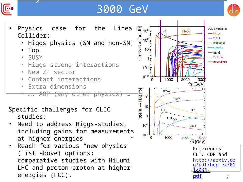
Physics at a LC from 250 GeV to 3000 GeV• Physics case for the Linear Collider:
• Higgs physics (SM and non-SM)• Top• SUSY• Higgs strong interactions• New Z’ sector• Contact interactions• Extra dimensions• …. AOP (any other physics) …
Specific challenges for CLIC studies: • Need to address Higgs-studies, including gains
for measurements at higher energies • Reach for various “new physics” (list above)
options; comparative studies with HiLumi LHC and proton-proton at higher energies (FCC).
References:CLIC CDR andhttp://arxiv.org/pdf/hep-ex/0112004.pdf
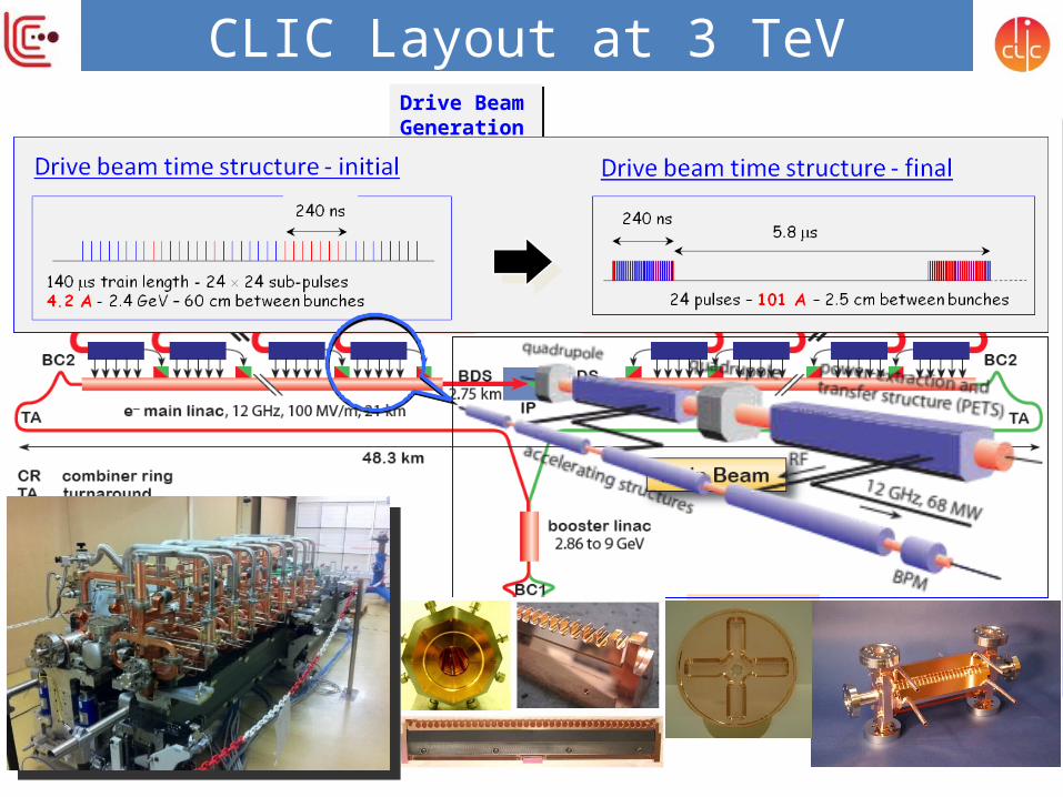
CLIC Layout at 3 TeVDrive Beam Generation Complex
Main Beam Generation Complex
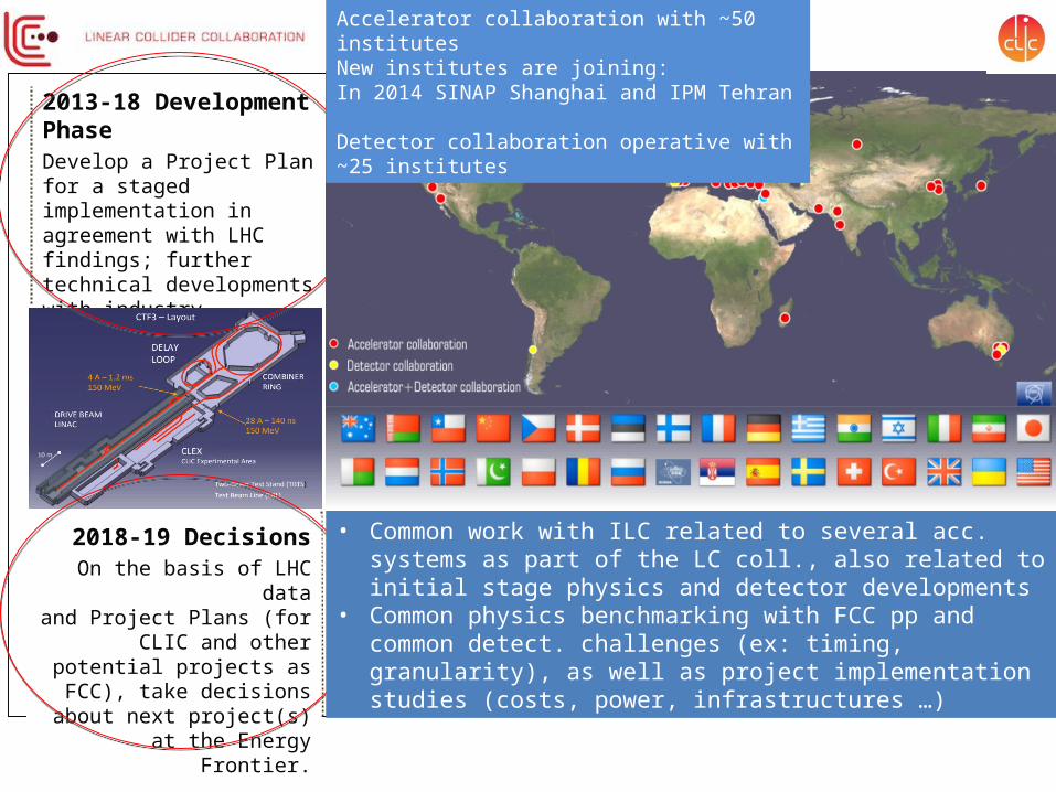
2013-18 Development PhaseDevelop a Project Plan for a staged implementation in agreement with LHC findings; further technical developments with industry, performance studies for accelerator parts and systems, as well as for detectors.
2018-19 DecisionsOn the basis of LHC data
and Project Plans (for CLIC and other potential projects as FCC),
take decisions about next project(s) at the Energy Frontier.
4-5 year Preparation PhaseFinalise implementation parameters, Drive Beam Facility and other system verifications, site authorisation and preparation for industrial procurement. Prepare detailed Technical Proposals for the detector-systems.
2024-25 Construction StartReady for full construction
and main tunnel excavation.
Construction Phase Stage 1 construction of CLIC, in parallel with detector construction.Preparation for implementation of further stages.
Commissioning Becoming ready for data-
taking as the LHC programme reaches
completion.
• Common work with ILC related to several acc. systems as part of the LC coll., also related to initial stage physics and detector developments
• Common physics benchmarking with FCC pp and common detect. challenges (ex: timing, granularity), as well as project implementation studies (costs, power, infrastructures …)
Accelerator collaboration with ~50 institutesNew institutes are joining:In 2014 SINAP Shanghai and IPM Tehran Detector collaboration operative with ~25 institutes

5
Main activities
Covered this afternoon in talk by Eva Sicking
http://clic-study.web.cern.ch/content/clic-accelerator-
activities
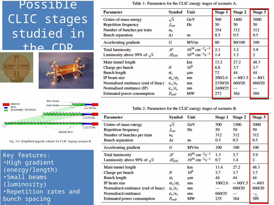
Possible CLIC stages studied in
the CDR
6
Key features: •High gradient (energy/length)•Small beams (luminosity)•Repetition rates and bunch spacing (experimental conditions)

Luminosity goal significantly impact minimum costFor L=1x1034cm-2s-1 to L=2x1034cm-
2s-1 :
Costs 0.5 a.u. and O(100MW)Cheapest machine is close to lowest power consumption
Cost/power: Design/parameters & Technical developments
Automatic procedure scanning over many structures (parameter sets)
Structure design fixed by few parameters
a1,a2,d1,d2,Nc,f,G
Beam parameters derived automatically
Cost calculated – and power
S=1.1
N [109]12
6.5L=0.5x1034cm-2s-1
L=1.0x1034cm-2s-1
L=2.0x1034cm-2s-1
L=1.0x1034cm-2s-1
L=1.25x1034cm-2s-1
L=1.5x1034cm-2s-1
L=2.0x1034cm-2s-1
Goal:•Rebaseline project at ~350 GeV, ~1.5 TeV, 3 TeV, very close to concluding this (talks in Friday plenary)
•Next natural steps: Optimised cost and power for given luminosity
•Hopefully needed to redo with new LHC results at some point
Beyond the parameter optimization there are other on-going developments (design/technical developments):•Use of permanent or hybrid magnets for the drive beam (order of 50’000 magnets)•Optimize drive beam accelerator klystron system •Electron pre-damping ring can be removed with good electron injector•Dimension drive beam accelerator building and infrastructure are for 3 TeV, dimension to 1.5 TeV results in large saving•Systematic optimization of injector complex linacs in preparation•Power consumption:
– Optimize and reduce overhead estimates

e+/e- Colliders: PAC vs ECM
8 8
CERN energy consumption 2012: 1.35 TWh
Power reductions are being looked at:•Design and parameters – optimise power•Look at key components – magnets•Klystron and modulator efficiences•Optimisation •Recover energy Consider where the power is dissipated (distributed or central)Look at daily and yearly fluctuation – can one run in “low general demand” periodsUnderstand and minimize the energy (consider also standby, MD, down periods, running scenarios

9
Developments for costs
CDR costs can now be updated•New parameters optimizing costs, affect mostly initial stages•Technical developments, affects all stages •Too early for updated industrial quotes in some areas (other areas can be updated)
2012 CHF versus 2015 CHF ?

High-gradient accel. structure test status
Results very good, design/performance more and more understood – but: •numbers limited, industrial productions also limited •basic understanding of BD mechanics improving •condition time/acceptance tests need more work•use for other applications (e.g. FELs) needs verification in coming years In all cases test-capacity is crucial
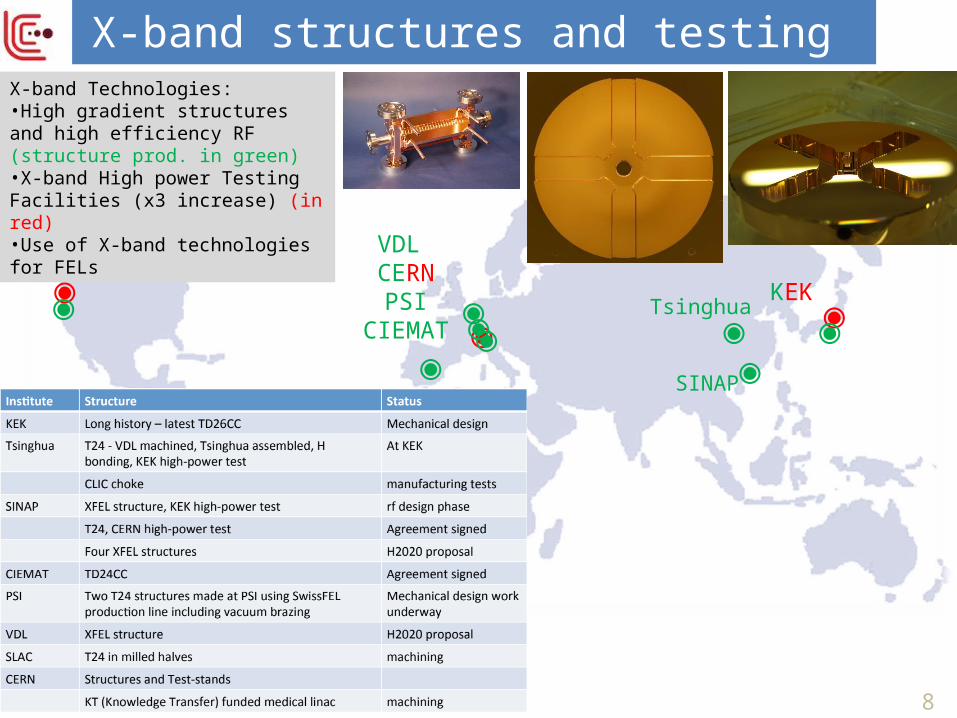
◉VDL
CERNPSI
CIEMAT ◉◉SLAC
◉KEK
8
X-band structures and testing
Tsinghua
SINAP
◉◉ ◉◉
X-band Technologies: •High gradient structures and high efficiency RF (structure prod. in green) •X-band High power Testing Facilities (x3 increase) (in red) •Use of X-band technologies for FELs
◉◉◉

NEXTEF at KEK
ASTA at SLAC
… remain important, also linked to testing of X-band structures from Tsinghua and SINAP
Previous:Scaled 11.4 GHztests at SLAC and KEK.
X-band test-stands
Very significant increase of test-capacity: •First commercial 12 GHz klystron systems available •Confidence that one can design for good (and possibly better) gradient performance •As a result: now possible to use Xband technology in accelerator systems – at smaller scale
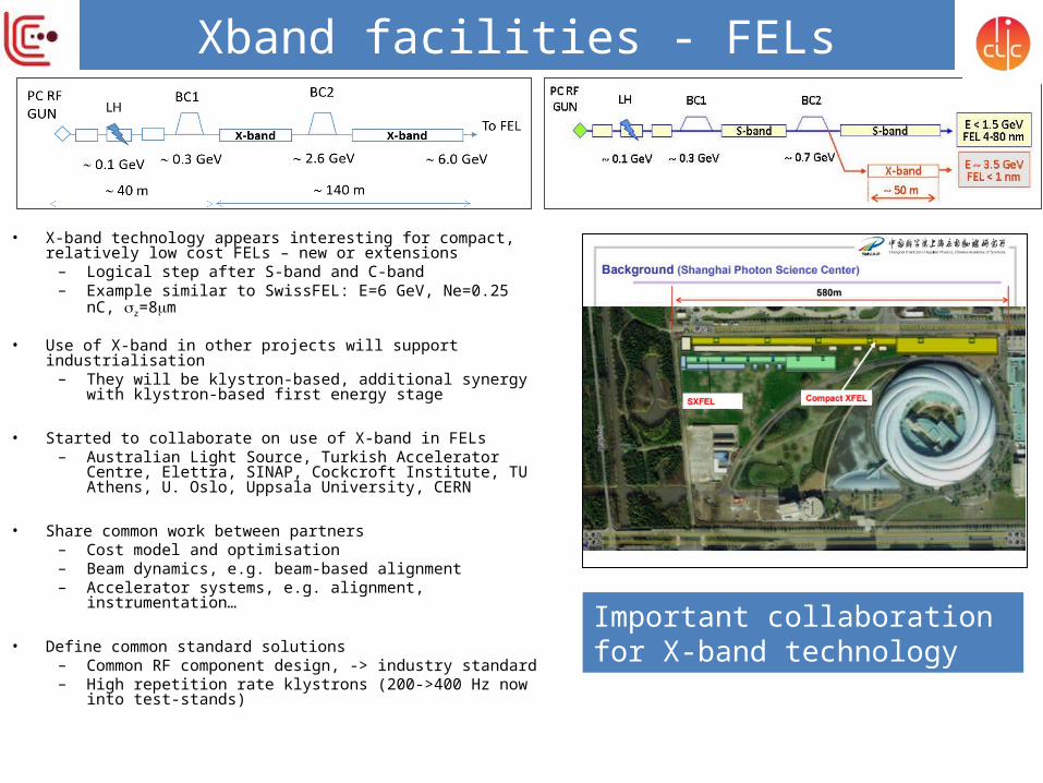
Xband facilities - FELs
• X-band technology appears interesting for compact, relatively low cost FELs – new or extensions
– Logical step after S-band and C-band– Example similar to SwissFEL: E=6 GeV, Ne=0.25 nC, z=8m
• Use of X-band in other projects will support industrialisation– They will be klystron-based, additional synergy with klystron-
based first energy stage
• Started to collaborate on use of X-band in FELs– Australian Light Source, Turkish Accelerator Centre, Elettra,
SINAP, Cockcroft Institute, TU Athens, U. Oslo, Uppsala University, CERN
• Share common work between partners – Cost model and optimisation– Beam dynamics, e.g. beam-based alignment– Accelerator systems, e.g. alignment, instrumentation…
• Define common standard solutions– Common RF component design, -> industry standard– High repetition rate klystrons (200->400 Hz now into test-
stands)
Important collaboration for X-band technology

14
Main activities

CLIC test facility - CTF3
Beam loading/BDR experiment
Two-Beam Module, Wake-field monitors, Two-beam studiesRF pulse shaping
Power production, RF conditioning/testing with DB & further decelerator tests
Phase feed-forward,DB stability studies
Dogleg experimentBreakdown rate measurement with presence of beam-loading-12 GHz CLIC structure-powered by 12 GHz RF (Xbox)-1.2 A CTF3 e- beam
First result: - beam has no negative result on breakdown rate
Combiner Ring
4th turn
1st turn

CLIC system tests beyond CTF3 • Drive beam development beyond CTF3
– RF unit prototype with industry using CLIC frequency and parameters
– Drive beam front-end (injector), to allow development into larger drivebeam facility beyond 2018
• Damping rings– Tests at existing damping rings,
critical component development (e.g. wigglers) ... large common interests with light source laboratories
• Main beam (see slide later)– Steering tests at FACET, FERMI, …
• Beam Delivery System (see slide later) – ATF/ATF2

Main Linac Tolerances
17
•Test of prototype shows• vertical RMS error of 11μm• i.e. accuracy is approx. 13.5μm
Stabilise quadrupoleO(1nm) @ 1Hz
Performance verifications – CLIC
2) Beam-based alignment
1) Pre-align BPMs+quadsaccuracy O(10μm) over about 200m
3) Use wake-field monitors accuracy O(3.5μm) – CTF3
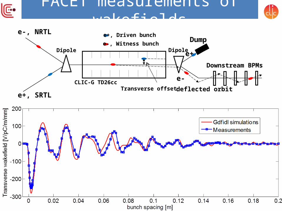
FACET measurements of wakefields
Transverse offset deflected orbit
Downstream BPMs
e-, NRTL
e+, SRTL
Dump
e+
e-CLIC-G TD26cc
DipoleDipole
e+, Driven bunche-, Witness bunch
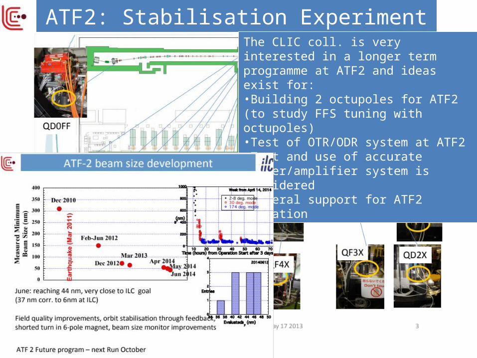
ATF2: Stabilisation ExperimentThe CLIC coll. is very interested in a longer term programme at ATF2 and ideas exist for:•Building 2 octupoles for ATF2 (to study FFS tuning with octupoles)•Test of OTR/ODR system at ATF2 •Test and use of accurate kicker/amplifier system is considered•General support for ATF2 operation

Technical activities – examplesTechnical Developments are motivated by several possible reasons: •Key components for systemtests •Critical for machine performance•Aimed at cost or power reduction
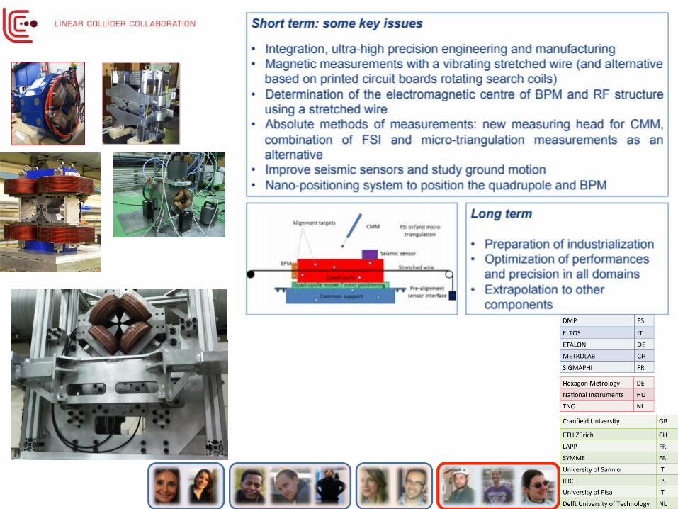

22
~260 registered (and ~200 talks)
Main elements:•Open high energy frontier session session (today) •Accelerator sessions focusing on collaboration efforts and plans 2015-2019, parallel sessions and plenary •High Gradient Applications for FELs, industry, medical •Physics and detector sessions on current and future activities•Collaboration and Institute Boards
Summary
23
The goals and plans for 2015-19 are well defined for CLIC, focusing on the high energy frontier capabilities – well aligned with current strategies – also preparing to align with LHC physics as it progresses in the coming years:•Aim provide optimized stages approach up to 3 TeV with costs and power not too excessive compared to LHC•Very positive progress on X-band technology, due to availability of power sources and increased understanding of structure design parameters
– Applications in smaller systems; FEL linacs key example – with considerable interesting in the CLIC collaboration
•Also recent good progress on performance verifications, drivebeam, main beam emittance conservation and final focus studies
– BBA discussions, BDS/ATF important – CTF3 running and plan until end 2016, strategy for systemtests beyond
•Technical developments of key parts well underway – with increasing involvement of industry – largely limited by funding •Collaborations for CLIC accelerator and detector&physics studies are growing
24
Thanks
• Slides/figures/advice from CLIC collaboration members Knowingly from L. Linssen, A. Latina, K.Kubo and ATF colleagues, D.Schulte, R.Corsini, W.Fang, W.Wuensch and X-band team, , F.Tecker, T.Lefevre, M.Modena, N.Catalan, C.Garion, H.Mainaud Durant and PACMAN team, R.Tomas, Y.Papaphilippou, G.D’Auria, … and several more unknowingly or indirectly