the daya bay antineutrino detectors - yale...
TRANSCRIPT

Daya Bay CD-2/3a Review, January 8, 2008 Karsten Heeger, Univ. Wisconsin 1
The Daya Bay Antineutrino Detectors
Karsten HeegerUniversity of WisconsinUS Antineutrino Detector System Manager
BNL CD-2/3a Review January 8, 2008

Daya Bay CD-2/3a Review, January 8, 2008 Karsten Heeger, Univ. Wisconsin 2
1. Scope of Task
2. Requirements & Design Overview
3. Main AD Subsystems - Detector Tank (PRC)- Acrylic Vessels (US/Taiwan)- Lifting (PRC)- Liquid Scintillator (PRC, US, Russia)- PMT AD Mechanical Systems (US)- AD Instrumentation (PRC, US)- AD Filling and Target Mass (US)- Assembly&Installation (PRC, US)
4. US cost, schedule, summary
Outline

Daya Bay CD-2/3a Review, January 8, 2008 Karsten Heeger, Univ. Wisconsin
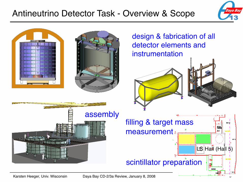
Antineutrino Detector Task - Overview & Scope
3
design & fabrication of all detector elements and instrumentation

Daya Bay CD-2/3a Review, January 8, 2008 Karsten Heeger, Univ. Wisconsin
Antineutrino Detector Task - Overview & Scope
4
design & fabrication of all detector elements and instrumentation
assembly
Daya Bay CD-2/3a Review, January 8, 2008 Karsten Heeger, Univ. Wisconsin
Antineutrino Detector Task - Overview & Scope
5
design & fabrication of all detector elements and instrumentation
assembly
scintillator preparation
LS Hall (Hall 5)
filling & target mass measurement

Daya Bay CD-2/3a Review, January 8, 2008 Karsten Heeger, Univ. Wisconsin
Antineutrino Detector Requirements
4 ANTINEUTRINO DETECTOR 83
4 Antineutrino Detector2922
The measurement of sin2 2!13 to <0.01 is an experimental challenge. A value of 0.01 for sin2 2!132923
yields a tiny oscillation effect. This corresponds to a small difference in the number of antineutrino events2924
observed at the far site from the expectation based on the number of events detected at the near site after2925
correcting for the distance under the assumption of no oscillation. To observe such a small change, the2926
detector must be carefully designed following the guidelines discussed in Chapter 1, and possible systematic2927
uncertainties discussed in Chapter 2. To make this measurement the antineutrino detector must meet the2928
physics performance requirements summarized in Table 4.1.
Item Requirement Justification
Target mass at far site !80 T Achieve sensitivity goal in three years over al-
lowed !m231 range
Precision on target mass "0.3% Meet detector systematic uncertainty baseline
per module
Energy resolution "15%/#
E Assure accurate calibration to achieve re-
quired uncertainty in energy-threshold cuts
(dominated by energy threshold cut)
Detector efficiency error <0.2% Should be small compared to target mass un-
certainty
Positron energy threshold "1 MeV Fully efficient for positrons of all energies
Radioactivity singles rate "100 Hz Limit accidental background to less than
other backgrounds and keep data rate man-
ageable
Table 4.1. Physical requirements of the antineutrino detector.
2929
The technical requirements of the individual subsystems for the antineutrino detector are summarized2930
in similar format at the beginning of each of the following sections.2931
In addition, the following considerations enter the design of the antineutrino detector:2932
1. The detector modules should be homogeneous to minimize edge effects.2933
2. It is important to precisely know the target mass and composition. The number of protons in the target2934
liquid scintillator should be well known, implying that the scintillator mass and the proton to carbon2935
ratio should be precisely determined. The target scintillator should come from the same batch for2936
each pair of near-far detector modules or for all detectors, and the mixing procedure should be well2937
controlled to ensure that the composition of each antineutrino target is the same.2938
3. The detector module should not be too large; otherwise, it would be difficult to move from one detector2939
site to another for cross check to reduce systematic effects. In addition, beyond a certain size, the rate2940
of cosmic-ray muons passing through the detector module is too high to be able to measure the 9Li2941
background.2942
4.1 Detector Geometry and Dimensions2943
Several previous neutrino experiments have designed spherical or ellipsoidal detectors to insure uniform2944
energy response in the entire volume. This type of detector vessel is expensive and requires many PMTs for2945
4" coverage. Two types of alternative detector geometries have been investigated: cubic and cylindrical.2946
Both are attractive from the viewpoint of construction. Monte Carlo simulation shows that a cylindrical2947
Physics Design Criteria3-zone detector with the following general characteristics
6
key feature of experiment: > “identical detectors” at near and far sites
detectors will never be identical but we can control relative target mass & composition to < 0.30% relative antineutrino detection efficiency to < 0.25% between pairs of detectors
≤50 Hz

Daya Bay CD-2/3a Review, January 8, 2008 Karsten Heeger, Univ. Wisconsin
Antineutrino Detector Requirements
4 ANTINEUTRINO DETECTOR 83
4 Antineutrino Detector2922
The measurement of sin2 2!13 to <0.01 is an experimental challenge. A value of 0.01 for sin2 2!132923
yields a tiny oscillation effect. This corresponds to a small difference in the number of antineutrino events2924
observed at the far site from the expectation based on the number of events detected at the near site after2925
correcting for the distance under the assumption of no oscillation. To observe such a small change, the2926
detector must be carefully designed following the guidelines discussed in Chapter 1, and possible systematic2927
uncertainties discussed in Chapter 2. To make this measurement the antineutrino detector must meet the2928
physics performance requirements summarized in Table 4.1.
Item Requirement Justification
Target mass at far site !80 T Achieve sensitivity goal in three years over al-
lowed !m231 range
Precision on target mass "0.3% Meet detector systematic uncertainty baseline
per module
Energy resolution "15%/#
E Assure accurate calibration to achieve re-
quired uncertainty in energy-threshold cuts
(dominated by energy threshold cut)
Detector efficiency error <0.2% Should be small compared to target mass un-
certainty
Positron energy threshold "1 MeV Fully efficient for positrons of all energies
Radioactivity singles rate "100 Hz Limit accidental background to less than
other backgrounds and keep data rate man-
ageable
Table 4.1. Physical requirements of the antineutrino detector.
2929
The technical requirements of the individual subsystems for the antineutrino detector are summarized2930
in similar format at the beginning of each of the following sections.2931
In addition, the following considerations enter the design of the antineutrino detector:2932
1. The detector modules should be homogeneous to minimize edge effects.2933
2. It is important to precisely know the target mass and composition. The number of protons in the target2934
liquid scintillator should be well known, implying that the scintillator mass and the proton to carbon2935
ratio should be precisely determined. The target scintillator should come from the same batch for2936
each pair of near-far detector modules or for all detectors, and the mixing procedure should be well2937
controlled to ensure that the composition of each antineutrino target is the same.2938
3. The detector module should not be too large; otherwise, it would be difficult to move from one detector2939
site to another for cross check to reduce systematic effects. In addition, beyond a certain size, the rate2940
of cosmic-ray muons passing through the detector module is too high to be able to measure the 9Li2941
background.2942
4.1 Detector Geometry and Dimensions2943
Several previous neutrino experiments have designed spherical or ellipsoidal detectors to insure uniform2944
energy response in the entire volume. This type of detector vessel is expensive and requires many PMTs for2945
4" coverage. Two types of alternative detector geometries have been investigated: cubic and cylindrical.2946
Both are attractive from the viewpoint of construction. Monte Carlo simulation shows that a cylindrical2947
Physics Design Criteria
7
key feature of experiment: > “identical detectors” at near and far sites
detectors will never be identical but we can control relative target mass & composition to < 0.30% relative antineutrino detection efficiency to < 0.25% between pairs of detectors
> vessel size
> reflector
> radiopurity> cleanliness
> identical vessels > minimum use of acrylic and other structures
> filling and target mass system
Requirements -> Design Features

Daya Bay CD-2/3a Review, January 8, 2008 Karsten Heeger, Univ. Wisconsin
Antineutrino Detector - Simulations
4 ANTINEUTRINO DETECTOR 89
)2(m2R
0 0.5 1 1.5 2 2.5 3 3.5 4 4.5
Photoelectron
0
50
100
150
200
250
300
350
400
Fig. 4.7. Antineutrino detector response (in number of photoelectrons) as a function of
the square of the radial location of a 1 MeV electron energy deposit. The mineral oil
volume has been removed and the PMTs are positioned directly outside the γ-catchervolume. The vertical blue line is 15 cm from the PMT surface and indicates the need
for at least 15 cm of buffer between the PMT surface and the region of active energy
deposit in order to maintain uniform detector response.
Distance of PMT Front Face to Gamma Catcher
Isotope Concentration 20 cm 25 cm 30 cm 40 cm
(Hz) (Hz) (Hz) (Hz)238U 40 ppb 2.2 1.6 1.1 0.6232Th 40 ppb 1.0 0.7 0.6 0.340K 25 ppb 4.5 3.2 2.2 1.3
Total 7.7 5.5 3.9 2.2
Table 4.2. Radiation from the PMT glass detected in the Gd-scintillator (in Hz) as a
function of the oil-buffer thickness (in cm). An oil buffer of more than 45 cm thickness
will provide 20 cm of shielding against radiation from the PMT glass.
reflective panels can be put close to the top and bottom of the γ-catcher vessel to enlarge the photocathode3043
coverage. As shown in Fig. 4.7, the photoelectron yield increases as the light source approaches the wall of3044
the detector. However, the detector response will be uniform in the direction of the axis of the cylinder if a3045
reflector with∼100% specular reflectivity is used.While specular and diffuse reflection have no difference in3046
the total photoelectron yield, specular reflection is preferred because it will simplify vertex fitting algorithms3047
(Sec. 4.2).3048
Using a reflector can also greatly simplify the mechanical design and assembly of the detector. To3049
4 ANTINEUTRINO DETECTOR 88
Gamma catcher thickness (cm)0 10 20 30 40 50 60 70 80 90
Eff
icie
ncy
(%
)
70
75
80
85
90
95
100
Fig. 4.6. The neutron detection efficiency as a function of the thickness of the !-
catcher. The neutron energy cut is set at 6 MeV. The thickness of the ! catcher of
the Daya Bay experiment will be 42.5 cm.
the vertex selection uncertainty, the resulting efficiency values are consistent with simulation. After a com-3018
prehensive study of detector size, detection efficiency, and experimental uncertainties, we choose 42.5 cm3019
as the thickness of the !-catcher.3020
4.1.5 Oil Buffer3021
The outermost zone of the detector module is composed of mineral oil. The PMTs will be mounted3022
in the mineral oil next to the stainless steel vessel wall, facing radially inward. This mineral oil layer is3023
optically transparent and emits very little scintillation light. There are two primary purposes for this layer:3024
1) to attenuate radiation from the PMT glass, steel tank and other sources outside of the module; and 2)3025
to ensure that PMTs are sufficiently far from the liquid scintillator so that the light yield is quite uniform.3026
Simulations indicate that the location of light emission should be at least 15 cm away from the PMT surface,3027
as indicated in Fig. 4.7.3028
The oil buffer is also used to attenuate radiation from the PMT glass into the fiducial volume. Simulation3029
shows that with 20 cm of oil buffer between the PMT glass and the liquid scintillator, the radiation from the3030
PMT glass detected in the liquid scintillator is 7.7 Hz, as summarized in Table 4.2.3031
The welded stainless steel in KamLAND has an average radioactivity of 3 ppb Th, 2 ppb U, 0.2 ppb3032
K, and 15 mBq/kg Co. Assuming the same radioactivity levels for the vessel of the Daya Bay antineutrino3033
detector module, the corresponding rate from the stainless steel tank can be found in Table 4.3. The total3034
rate is !20 Hz.3035
The natural radioactivity of rock, buffer water, mineral oil, dust, radon and krypton in air play a minor3036
role, as described in Section 2.3.4. The total ! rate is <50 Hz. The oil buffer will be sufficient to suppress3037
the ! rate and the subsequent uncorrelated backgrounds to an acceptable level.3038
The dimensions of the antineutrino detector modules are shown in Table 4.4.3039
4.1.6 Optical Reflective Panels3040
Optical reflective panels will be put at the top and bottom of the cylinder. PMT numbers can be reduced3041
to nearly one half comparing to the 4" PMT installation, while keeping the same photocathode coverage. The3042
Detector Design and Geant4 Simulationsgamma catcher thickness
MO buffer thickness Gd-LS(20 tons)
-> for details see the TDR
< 5m (tunnel limitations)
> 15cm buffer between PMT and OAV
= 42.5cm gamma catcher
8
Dimensions of 3-Zone Detector
LS
MO

Daya Bay CD-2/3a Review, January 8, 2008 Karsten Heeger, Univ. Wisconsin
Antineutrino Detector - OverviewA Short Guide to the AD
• PMT cable feedthroughs and dry boxes
• calibration boxes• gas and electrical distribution
boxes• overflow tanks• calibration pipes• auxiliary ports for monitoring
and filling• PMTs• PMT ladders and mounts• inner 3-m acrylic vessel• acrylic support ribs • outer 4-m acrylic vessel• stainless steel vessel
9

Daya Bay CD-2/3a Review, January 8, 2008 Karsten Heeger, Univ. Wisconsin
Antineutrino Detector - Scope&Responsibilities
Taiwan - blue- 3m acrylic vessel with bonded lid US - orange - 4m acrylic vessel with removable lid - acrylic overflow tanks for Gd-LS and LS- calibration pipes + bellows- overflow tank instrumentation- PMT mounts and ladders- PMTs, bases, and testing- PMT cables and feedthroughs- Gd-LS and LS
PRC - grey - stainless steel vessel (SSV)- SSV lid - reflector- mineral oil (MO) overflow tank- overflow tank instrumentation- Gd-LS, LS, and MO
10
A Broad Overview (details in MOU list of deliverables)

Daya Bay CD-2/3a Review, January 8, 2008 Karsten Heeger, Univ. Wisconsin
Organization, Management, WBS
1.1 Detector Tank (Zhuang, IHEP)
1.2 Acrylic Vessels (Heeger, UW / Hsiung, NTU)
1.3 Liquid Scintillator (Yeh, BNL / Zhang, IHEP)
1.4 PMT AD Mechanical Systems (Virostek, LBNL / Cherwinka, UW)
1.5 System for Measuring Physical Detector Properties (Wise, UW)
1.6 Lifting (Zhuang, IHEP)
1.7 Materials & Compatibility Testing (Yeh, BNL / Chen, IHEP)
1.8 Other AD Systems (Wise, UW)
1.9 AD Integration (Heeger, UW / Cao, IHEP)
1.10 AD Assembly & Installation (Cherwinka, UW / Cao, IHEP)
1.11 Subsystem Management (Heeger, UW / Cao, IHEP)
11
L3 ManagementAntineutrino Detector Co-Managers Jun Cao, IHEP - China
Karsten Heeger, UW - USA
L3s combination of scientists and engineers as appropriate for subsystems

Daya Bay CD-2/3a Review, January 8, 2008 Karsten Heeger, Univ. Wisconsin
Acrylic Vessel System (WBS 1.1.2)
3m vessel 4m vessel
lids
ribs and support structure
calibration pipe connectionsPair of Nested Vessels
FEA analysis of worst case scenario:uneven filling
independent FEA by UW-PSL and Reynolds Polymer Technology → stress still below
long-term limit12

Daya Bay CD-2/3a Review, January 8, 2008 Karsten Heeger, Univ. Wisconsin
AV Prototype - 4m Vessel at Reynolds (WBS 1.1.2)
Status- Reynolds built 4m vessel prototype vessel - design of 4m prototype essentially same as fabrication vessel- UW team surveyed vessel, meets specifications.- AV FDR in Dec 07. - will finalize fabrication drawings in Jan 2008, almost ready for procurement -> long lead item
before bonding AV bottom 13
Daya Bay CD-2/3a Review, January 8, 2008 Karsten Heeger, Univ. Wisconsin
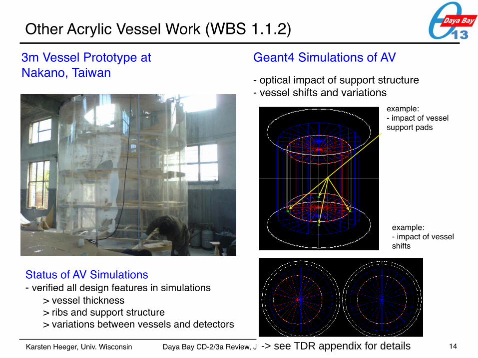
Other Acrylic Vessel Work (WBS 1.1.2)
December 6, 2007 Bryce LittlejohnUniv. Wisconsin - Madison
Simulation Setup
• Use G4dybApp.exe to simulate AD with and without pads
• Viton material not defined; used stainless steel:
• relatively non-reflective
• very short path length in material
• serves as a good worse-case estimate
• Checked detector response to:
• 1 MeV electrons: ~800k events
• 8 MeV electrons: ~100k events
• Q: Why electrons? A: Quicker simulation!
• All Events generated in GDLS
3
3m Vessel Prototype at Nakano, Taiwan
Geant4 Simulations of AV- optical impact of support structure- vessel shifts and variations
Status of AV Simulations- verified all design features in simulations
> vessel thickness> ribs and support structure> variations between vessels and detectors
example:- impact of vessel support pads
example:- impact of vessel shifts
!!
"
!!"#$%&'()*&+(%",()-(.#('/01),.)2&%"*/&'".,)
3"3(+)./)+$33./')+'/$2'$/(+4
!!5"6')",,(/)&2/0%"2)7(++(%)85"%()%(&7",-).$'(/)
&2/0%"2)7(++(%)2(,'(/(9)",)9('(2'./
!):.#3&/()+'&,9&/9);<)#('/"2+)&')9"66(/(,')
%.2&'".,+1
"=66"2"(,20
"=,(/-0)!2&%()>,2(/'&",'0
?;@)!5"6')!('$3
-> see TDR appendix for details 14

Daya Bay CD-2/3a Review, January 8, 2008 Karsten Heeger, Univ. Wisconsin
Gd Liquid Scintillator Production (WBS 1.1.3)
15
Requirements
high-light yield
3-Phase Process and Production plan1. Procurement of chemical and purification equipment -> long lead item2. Mass production of Gd-solid (~1 ton): organo-gadolinium solid will be synthesized at IHEP,
transported to Daya Bay and dissolved in LS Hall underground3. Dissolution and mixing of 0.1% Gd-LS (~200 tons): 200 tons of LS (LAB + fluors) will be
prepared first, followed by 200 tons of Gd-LS (Gd-LAB + fluors) production
Progress Since CD-1• In-lab R&D for Gd-LS synthesis finished in
04/2007.• Aging test (40 C) has been running since
07/2007.• Baseline plan of final Gd-LS production
selected in 08/2007.• Scope distribution between US and China
finished in 09/2007.
Stability Tests of Gd-LS(UV absorption values at 430 nm)
days
abso
rptio
n va
lue

Daya Bay CD-2/3a Review, January 8, 2008 Karsten Heeger, Univ. Wisconsin
Gd Liquid Scintillator Production (WBS 1.1.3)
16
Solid Production Process
Status• PDR of Gd-LS synthesis and
handling in Oct 07• FDR of Gd-LS production in
Mar 08
LS Mixing and Preparation Undergroundin LS Filling Hall (Hall 5)
Gd-LS mixing
212t LS
185t Gd-LS
176t MO AD

Daya Bay CD-2/3a Review, January 8, 2008 Karsten Heeger, Univ. Wisconsin
PMT Mounts and Ladders (WBS 1.1.4)
17
PMT Mounts• A pair of prototype mounts is currently being fabricated• Cost estimate close to that of MiniBoone• Material for interface pads between mounts and PMT’s still must be
identified and tested for MO compatibility
PMT Ladders• Ladder has been integrated with the SSV final design and other
internal AD components• Ladder is installed at a slight angle to clear SSV flange and to allow
adequate clearance from outer AV after installation• Ladder design allows for placement of an optical shield

Daya Bay CD-2/3a Review, January 8, 2008 Karsten Heeger, Univ. Wisconsin
PMT Cable Feedthroughs and Drybox (WBS 1.1.4)
to electronics
to PMTs
Objective- PMT cables carrying the signals from the PMTs must pass through the walls of tank - convenient to have electrical break in the cable to allow for easier transportation and testing of the ladder as well as movement of the ADs. - dry box houses this electrical junction.
Design Features- design also facilitates testing and provides possibility for corrective action if a leak develops. - allows good leak checking of all seals- cables paths adjusted to same length- electrical cables connected with flange held open
Status - design essentially final- prototype under construction- PDR in Dec 07- FDR in March 2008
18

Daya Bay CD-2/3a Review, January 8, 2008 Karsten Heeger, Univ. Wisconsin
MO overflow 1
MO overflow 2
Calib. box 10
Calib. box 12
Calib. box 11
gas distribution boxelectrical interface box
Central overflow
MO attenuation length monitoring device MO fill
LED wiring
MO fill monitor
Antineutrino Detector Lid

Daya Bay CD-2/3a Review, January 8, 2008 Karsten Heeger, Univ. Wisconsin
central calibration tube off-center calibration tubes
GDLS overflow
LS overflow
calibration boxes(see calibration talk)
concentric Teflon bellows
Overflow Tanks & Calibration Tubes (WBS 1.1.5)
gate valves
expected liquid level

Daya Bay CD-2/3a Review, January 8, 2008 Karsten Heeger, Univ. Wisconsin
AD Target Monitoring and Instrumentation (WBS 1.1.5)
MO level sensors, 2 types(pressure, ultrasound)
LS visual level monitor(CCD)
Gd-LS visual level monitor(CCD)s
LS level sensors, 2 types(pressure, ultrasound)
Gd-LS level sensors, 2 types(pressure, ultrasound)
Karsten Heeger, Univ. Wisconsin December 12, 2007
Ultrasonic Thickness Gauge
- started some R&D on measuring liquid heights with ultrasonic
> need to immerse transducer in liquid. cannot measure through air or acrylic.
> watertight transducers are available or can be obtained through potting electrical
connections
> mm accuracy seems attainable. some systematic issues to be studied
(reflections from wall etc.)
ultrasonic gauge
pressure sensor
CCD camera to monitor fill level
21
Daya Bay CD-2/3a Review, January 8, 2008 Karsten Heeger, Univ. Wisconsin 22
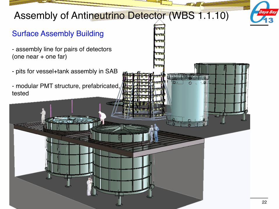
Assembly of Antineutrino Detector (WBS 1.1.10) Surface Assembly Building
- assembly line for pairs of detectors (one near + one far)
- pits for vessel+tank assembly in SAB
- modular PMT structure, prefabricated, tested
Daya Bay CD-2/3a Review, January 8, 2008 Karsten Heeger, Univ. Wisconsin
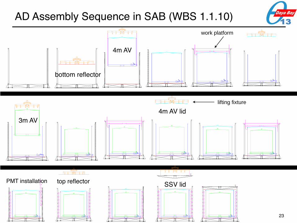
AD Assembly Sequence in SAB (WBS 1.1.10)
4m AV
bottom reflector
3m AV
top reflector SSV lid
4m AV lid
work platform
lifting fixture
23
PMT installation

Daya Bay CD-2/3a Review, January 8, 2008 Karsten Heeger, Univ. Wisconsin
AD Assembly Sequence in SAB (WBS 1.1.10)
4m AV
bottom reflector
3m AV
top reflector SSV lid
4m AV lid
work platform
lifting fixture
Nov 10, 2008
Jan 23, 2009
Feb 27, 2009 Apr 25, 2009
dates for AD #1,2 assembly
Dec 17, 2008
- AD fully assembled but not filled
24

Daya Bay CD-2/3a Review, January 8, 2008 Karsten Heeger, Univ. Wisconsin 25
Moving the Detector Underground
1. Installation and Deployment - moving down <10% grade when empty (20 t) - moving on 0.5% tunnel grade when full (100 t) - lifting full AD into water pool (100t)2. Detector Swapping (optional)
transporter
lifting
< 10%
< 0.5%
< 0.5%
Note: transporter part of WBS 1.7
LS Hall

Daya Bay CD-2/3a Review, January 8, 2008 Karsten Heeger, Univ. Wisconsin 26
Filling the Detector & Measuring the Target Mass (WBS 1.1.5)
Gd-LS
LSMO
I. Target: 0.1% Gd-loaded liquid scintillator (Gd-LS)II. γ-catcher: liquid scintillator (LS)III. Buffer shielding: mineral oil (MO)
Three Detector Liquids:
Filling Requirements- all detector volumes have to be filled simultaneously to minimize stress on AVs- detectors are filled “in pairs” from common storage tanks, i.e. in sequence within a short period of time (~ 1-2 weeks)- filling system must be compatible with Gd-LS, LS, and MO
Target Mass Measurement Requirements- Gd-LS target mass measured to < 0.1%- LS and MO mass measured to < 0.5%
- redundant measurement methods: > load cells, > Coriolis mass flow meters, > electromagnetic flow meters
conceptual drawing of detector filling with equal fill levels

Daya Bay CD-2/3a Review, January 8, 2008 Karsten Heeger, Univ. Wisconsin
load cell equipped Gd-LS ISO weighing tank with < 20 t capacity
flow meters
diaphragm pump
AD Filling System & Target Mass Measurement (WBS 1.1.5)
calibration boxes removed during AD filling
Sartorius load cell accuracy < 0.015% pulse
damper
Gd-LS
purge/waste container
Gd-LS
MO
LS

Daya Bay CD-2/3a Review, January 8, 2008 Karsten Heeger, Univ. Wisconsin
load cell equipped Gd-LS ISO weighing tank
flow meters
diaphragm pump
AD Filling System & Target Mass Measurement (WBS 1.1.5)
calibration boxes removed during AD filling
Sartorius load cell accuracy < 0.015% pulse
damper
Gd-LS
LS
MO
purge/waste container
Gd-LS
MO
LS

Daya Bay CD-2/3a Review, January 8, 2008 Karsten Heeger, Univ. Wisconsin
load cell equipped Gd-LS ISO weighing tank
flow meters
diaphragm pump
AD Filling System & Target Mass Measurement (WBS 1.1.5)
calibration boxes removed during AD filling
Sartorius load cell accuracy < 0.015% pulse
damper
Status- load cells tested, accuracy verified- ISO tank specifications drafted, ready for procurement, -> long lead item- PDR of system in Oct 07- FDR of system in March 08
Gd-LS
LS
MO
purge/waste container
Gd-LS
MO
LS

Daya Bay CD-2/3a Review, January 8, 2008 Karsten Heeger, Univ. Wisconsin
Antineutrino Detector Design Status & Reviews
• Jul/Aug 2007 – AD PDR
• Oct 2007 – Steel Vessel FDR– LS Hall and Gd-LS Synthesis PDR
• Dec 2007 – PMT FDR– AV and SSV Lid FDR – PMT AD Mechanical Systems PDR
• Mar/Apr 2008– Gd-LS production and LS Hall FDR– PMT AD Mechanical Systems FDR
30
PDR = prelim design reviewFDR = final design review
> completed FDRs in green

Daya Bay CD-2/3a Review, January 8, 2008 Karsten Heeger, Univ. Wisconsin
Antineutrino Detector Design Status & Reviews
• Jul/Aug 2007 – AD PDR
• Oct 2007 – Steel Vessel FDR– LS Hall and Gd-LS Synthesis PDR
• Dec 2007 – PMT FDR– AV and SSV Lid FDR – PMT AD Mechanical Systems PDR
• Mar/Apr 2008– Gd-LS production and LS Hall FDR– PMT AD Mechanical Systems FDR
31
PDR = prelim design reviewFDR = final design review
> completed FDRs in green
→ long-lead item: PMTs→ long-lead item: 4m AVs
→ long-lead item: Gd-LS chemicals→ long-lead item: ISO tank

Daya Bay CD-2/3a Review, January 8, 2008 Karsten Heeger, Univ. Wisconsin
AD Baseline Cost and Contingency
32
20%
Antineutrino Detector WBS & Cost (US scope)
o 4-m acrylic vessels + lids + overflow tanks o target mass measurement and filling system
PRC scope
PRC scope

Daya Bay CD-2/3a Review, January 8, 2008 Karsten Heeger, Univ. Wisconsin
Antineutrino Detector Selected Risks & Further R&D
Risk, R&D, and Development Items
• Gd-LS Production (risk)– time for large-scale, batch production– long-term degradation of Gd-LS
• Materials Compatibility (risk, R&D)– Gd-LS, LS, MO degradation due materials
incompatibility– materials compatibility study and archive of all detector
materials
• Fabrication QA (R&D)– finalizing consistent QA plan for all AD subsystems
between countries and continents
• AD Assembly & Installation (R&D)
– develop and build special tooling for AD assembly and installation. conceptual designs exist.
33
→ ongoing R&D
→ full-scale batch test in spring 2008
→ ongoing program
→ ongoing effort, visit to fabrication facilities, sharing of samples
→ ongoing effort with PDR and FDR planned in 2008
→ see risk registry for details

Daya Bay CD-2/3a Review, January 8, 2008 Karsten Heeger, Univ. Wisconsin
Schedule and Milestones
34
• CD-2 review• start fabrication of acrylic vessels #1,2• complete chemical procurement for Gd-LS and LS• PMT mounts and ladders at Daya Bay • acrylic vessels #1, 2 delivered to Daya Bay• mixing of LS and Gd-LS begins in LS Hall• target mass system installed in LS Hall• LS Hall ready for AD filling • complete assembly of AD #1,2• complete filling of AD #1,2• Daya Bay near site ready for data taking• complete assembly of AD #3,4• complete assembly of AD #5,6• complete assembly of AD #7,8• Ling Ao near site ready for data taking• Daya Bay far site ready for data taking
Jan 08Apr 08Jul 08Dec 08Dec 08Jan 09May 09May 09May 09Jul 09Nov 09Sep 09Dec 09Jun 10Jul 10Dec 10

Daya Bay CD-2/3a Review, January 8, 2008 Karsten Heeger, Univ. Wisconsin
Summary
• Antineutrino Detector System is in an advanced design stage, PDRs for all subsystems and FDRs for major detector elements.
• Critical and novel detector elements have been prototyped or prototypes are being evaluated (AVs, PMT feedthroughs, precisions load cells, etc.)
• Simulation for all principal detector elements completed. • Cost estimates for major subsystems based on full-size
prototype work (e.g. AVs)• Antineutrino Detector system expected to meet or exceed
(e.g target mass) design requirements. • Construction of subsystem elements can begin in Spring
2008 and will meet international project schedule.
35